

Page 1
www.extron.com
© 2008 Extron Electronics. All rights reserved.
Pricing and specifications may change without notice.
USA West
+1.714.491.1500 / +80 0.633.9876
+1.714.491.1517 FAX
USA East
+1.919.86 3.1794 / +80 0.633.9876
+1.919.86 3.1797 FA X
China
+ 86.21.3760.1568 / +4 00.883.1568
+ 86.21.3760.1566 FAX
Japan
+81.3. 3511.7655
+81.3. 3511.7656 FAX
Europe
+31.33 .453.4 040 / +800. 3987.6673
+31.33 .453.4 050 FA X
Dubai
+97 1.4.299 1800
+97 1.4.299 1880 FAX
Asia
+65.6 383.440 0 / +800.7339. 8766
+65.6 383.4664 FAX
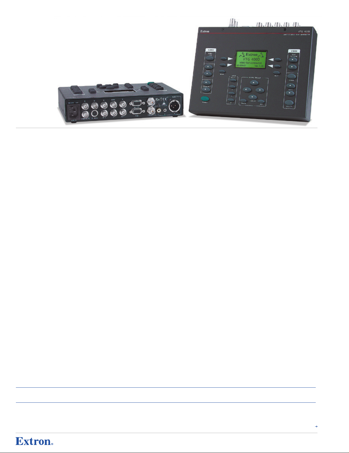
VTG 400D
Programmable Video and Audio Test Generator with
SDI/HD-SDI Output
FeaTur es
• Video outputs: RGBHV on BNC and 15-pin HD connectors, component video on
BNC connectors, S-video on a 4-pin mini DIN connector, composite video on a
BNC connector, and SDI/HD-SDI on a BNC connector
• Audio outputs: 3-pin XLR connector, RCA connector, and 3.5 mm mini stereo
audio jack
• 34 video test patterns — Includes multiple crosshatch patterns, color bars, PLUGE,
crop patterns, geometry, grayscale, and alternating pixel patterns, as well as flat field,
window, checkerboard, hum bar, and Patent Pending CTG Contrast Transfer Function
patterns with adjustable levels.
• Seven audio test signals — Includes sine waves, square waves, pink noise, white
noise, polarity, frequency sweeps, and sine wave bursts with selectable frequencies and
output levels.
• 101 selectable output rates including high resolution computer-video, HDTV, and
NTSC/PAL video — Provides 101 factory scan rates for high resolution computer-video,
HDTV, 16:9, plasma, and RGB, as well as standard definition component video, S-video,
and composite video. Also accommodates up to 180 additional user-defined scan rates.
• Patent Pending Scope-Trigger™ expedites signal/system troubleshooting when
using an oscilloscope — An innovative feature which enables analysis of a specific
area within the test pattern image using an oscilloscope. This feature is especially
helpful in identifying signal and display imperfections.
• Four Quick Select memory presets — User settings including output scan rates and
test signal selections can be saved to and recalled from four memory presets via direct
access buttons.
• Broadcast quality video encoder — Ensures compliance with SMPTE and NTSC/PAL
standards for accurate video performance.
• Auto Sequence mode — Specific test patterns can be selected for a repeating
sequence with selectable time intervals.
• Selectable RGB color output — The red, green, or blue color channel can be enabled
or disabled via the set-up menu.
• Auto-memory recall — Settings are saved when the VTG 400D is turned off and
automatically recalled when subsequently powered.
• RS-232 serial control port for custom scan rate programming, firmware upgrades,
and control with Extron SIS™ Simple Instruction Set
• Screen Saver mode — An adjustable timer can be set to engage the VTG 400D in
Screen Saver mode, with either the video output muted or as a repeating sequence of
test patterns.
• Main panel security lockout — All main panel controls except the power button can be
locked out to prevent unauthorized use or tampering.
t e S t Ge n e r a t o r S & Me a S u r e M e nt p r o d u c t S
VTG 400D
• Rugged metal enclosure — Appropriate for field use, but can also be placed on a
desktop. For added protection and portability, a soft nylon carrying case is included.
• Internal international power supply — The 100-240VAC, 50/60 Hz, universal power
supply provides worldwide power compatibility.
descr IPTIo n
The Extron VTG 400D is an advanced, programmable, and upgradeable Video and Audio Test
Generator that delivers accurate, full bandwidth video signal reproduction and high performance
audio test signals. This test generator is a professional quality reference tool for set-up,
performance evaluation, calibration, and troubleshooting audio and video systems.
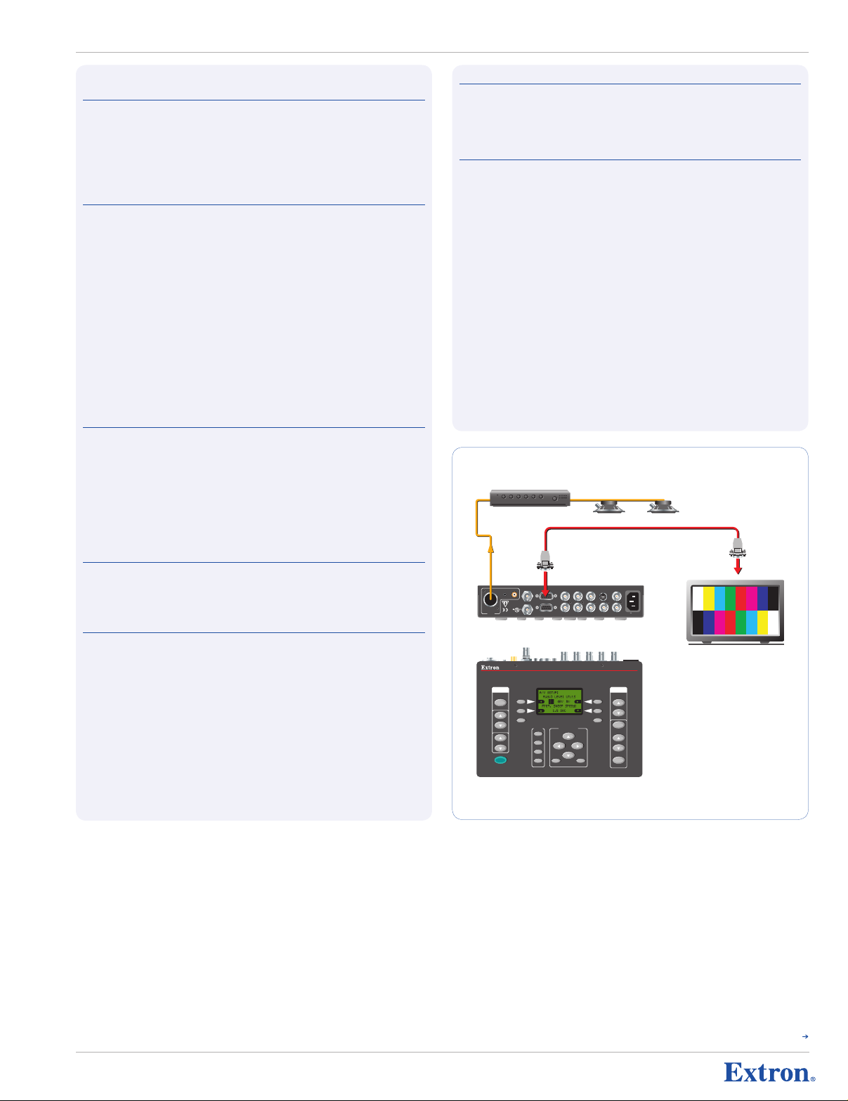
The VTG 400D offers a comprehensive array of video test patterns, as well as a suite of audio
reference signals. High resolution RGB computer-video is output simultaneously on BNC and
15-pin HD connectors. NTSC and PAL video is output simultaneously as RGB, component video,
S-video, and composite video, while audio output is both balanced on XLR and unbalanced on
RCA and 3.5 mm mini jack. An SDI/HD-SDI output is included with the VTG 400D.
The VTG 400D is designed for universal video display compatibility. A total of 101 output
scan rates are available for high resolution computer-video, as well as HDTV, NTSC, and PAL.
Up to 180 additional rates can be programmed into the VTG 400D. The audio test generator
is fully compatible with professional and consumer audio equipment, and delivers accurate
performance for microphone level inputs.
Operation of the VTG 400D is intuitive and convenient, with an easy-to-read LCD screen on
the main panel, direct access buttons, and memory presets for quick saving and recall of user
settings. Programming, upgrading, and adding new test patterns and custom scan rates to the
VTG 400D are available through RS-232 using the included Extron control software.
A powerful and innovative feature is the Patent Pending Scope-Trigger™ output, which enables
analysis of a selected area within the video image using an oscilloscope. Scope-Trigger delivers
quick and easy oscilloscope operation with minimal effort. Any desired location, or pixel, within
a video image can be accurately targeted and then simultaneously examined on an oscilloscope
via a precisely timed trigger signal from the VTG 400D.
Housed in a rugged, lightweight metal enclosure, the VTG 400D is ideal for both field and
permanent A/V applications.
ModeL VersIon d escrIPTIon ParT #
VTG 400D Test Generator with SDI/HD-SDI Output . . . . . . . . . . . . . . . . . . . . . . . . . . . . . . . . . . . . . . . . . . . . . . . . . . . . . . . . . . . . . . 60-564-02
oPTIonaL accessorIes ModeL des crIPTIon PaGe ParT #
SVHSM-BNCF 8" (20 cm) S-Video Male to 2 BNC Female Adapter . . . . . . . . . . . . . . . . . . . . . . . . . . . . . . . . . . . . . . . . . . . . page 795 26-353-01
SYM BNCF/0.5 15-pin HD Male to BNC Female Mini High Resolution Cables . . . . . . . . . . . . . . . . . . . . page 777 26-531-01
SYM BNCM/6 15-pin HD Male to BNC Male Mini High Resolution Cables . . . . . . . . . . . . . . . . . . . . . . . page 776 26-533-02
680
Continued
Page 2
RS-232
50-60Hz
COMPOSITE
R G B H/HV V
S-VIDEO R-Y Y B-Y RGB
TRIGGER
AUDIO
1 2 3
SDI/HDSDI
100-240V 0.3A
LISTED
1T23
I.T.E.
Power Amplier
Audio
Video
Plasma Display
Extron
VTG 400D
Video & Audio
Test Generator
Extron 15-pin HD
VGA Cable
AUDIO
SIGNAL
TYPE
LEVEL
POWER
FREQUENCY
VIDEO
TEST
PATTERN
RANGE
SELECT
RATE
MENU
QUICK
SELECT
SCOPE -TRIGGER
1
2
3
CURSOR
SHAPE HIDE
4
NEXT
VTG 400
VIDEO & AUDIO TEST GENERATOR
China
+ 86.21.3760.1568 / +4 00.883.1568
+ 86.21.3760.1566 FAX
Japan
+81.3. 3511.7655
+81.3. 3511.7656 FAX
Europe
+31.33 .453.4 040 / +800. 3987.6673
+31.33 .453.4 050 FA X
Dubai
+97 1.4.299 1800
+97 1.4.299 1880 FAX
Asia
+65.6 383.440 0 / +800.7339. 8766
+65.6 383.4664 FAX
China
+ 86.21.3760.1568 / +4 00.883.1568
+ 86.21.3760.1566 FAX
Japan
+81.3. 3511.7655
+81.3. 3511.7656 FAX
Europe
+31.33 .453.4 040 / +800. 3987.6673
+31.33 .453.4 050 FA X
Dubai
+97 1.4.299 1800
+97 1.4.299 1880 FAX
Asia
+65.6 383.440 0 / +800.7339. 8766
+65.6 383.4664 FAX
VTG 400D
t e S t Ge n e r a t o r S & Me a S u r e M e nt p r o d u c t S
sPecI FIcaTI ons
VId eo sIGn aL char acT erI sTIc s
Dot clock . .. .. .. . .. .. . .. .. . .. .. . .. . 200 MHz (max.)
Pixel clock accuracy . .. .. .. . .. .. 100 ppm
Horizontal frequency range
(factory defaults) . .. .. . .. .. .. . .. .. . 15 kHz to 131 kHz
Vertical frequency range
(factory defaults) . .. .. . .. .. .. . .. .. . 30 Hz to 120 Hz
Rise / Fall time
NTSC, PAL . .. .. . .. .. .. . .. .. . .. .. . .. 140 ns
All other signal rates .. . .. .. . .. .. . . <4 ns
VId eo ouTP uT
Number / Signal type . .. .. . .. .. . 1 RGBHV, RGBS, RGsB, RsGsBs, component video, HDSDI (SMPTE 292M,
Connectors . .. .. . .. .. . .. .. . .. .. .. . 1 x 5 female BNC (RGB)
Nominal level . .. . .. .. . .. .. . .. .. . . 1 Vp-p for Y of component video and S-video, and for composite video, RsGsBs
Minimum / Maximum levels .. . 0.0 V to 1.0 Vp-p
Impedance .. .. . .. .. . .. .. . .. .. . .. .. 75 ohms
Resolutions . .. .. . .. .. . .. .. . .. .. .. . Computer (VGA–QXGA), video (NTSC, PAL), HDTV, 16:9 high resolutions, and
Return loss . .. .. . .. .. . .. .. . .. .. .. . -30 dB @ 5 MHz
DC offset .. .. . .. .. . .. .. . .. .. . .. .. . . 0 ±5 mV for RGB and component video,
syn c
Output type .. .. .. . .. .. . .. .. . .. .. . . RGBHV, RGBS, RGsB, RsGsBs (for RGB signals)
Standards .. . .. .. . .. .. .. . .. .. . .. .. . NTSC, PAL, SMPTE 170M, SMPTE 274M, SMPTE 293M, SMPTE 295M,
Output level . .. . .. .. . .. .. . .. .. . .. . 0.3 Vp-p for RGsB, RsGsBs, component video (bi-level sync)
Output impedance . .. . .. .. . .. .. . 75 ohms
Max. Rise / Fall time . .. .. .. . .. .. 5 ns (TTL sync)
Polarity .. .. . .. .. . .. .. . .. .. . .. .. . .. . Positive or negative (scan rate/signal dependent)
Scope trigger connectors .. . .. . 1 BNC female (scope trigger)
aud Io
THD + Noise .. . .. .. . .. .. . .. .. . .. .. <0.008% typical @ +6 dBu (1.55 V), 1 kHz
Flatness .. .. . .. .. .. . .. .. . .. .. . .. .. . ±0.05 dB @ 20 Hz to 20 kHz
Accuracy .. .. .. . .. .. . .. .. . .. .. . .. .. ±0.4 dB
NOTE: 0 dBu = 0.775 Vrms, 0 dBV = 1 Vrms, 0 dBV ≈ 2 dBu
aud Io ouTP uT
Number / Signal type . .. .. . .. .. . 1 mono, balanced; 2 mono, unbalanced
Connectors . .. .. . .. .. . .. .. . .. .. .. . (1) 3.5 mm mini stereo jack (unbalanced mono left and right, tip-ring-sleeve)
Impedance .. .. . .. .. . .. .. . .. .. . .. .. 50 ohms unbalanced, 100 ohms balanced
Waveforms . .. .. . .. .. . .. .. . .. .. . .. Pink noise, white noise, sine wave (fixed/swept burst), square wave, polarity test
Level ranges . .. . .. .. . .. .. . .. .. . .. Pink noise: -72 dBu to -4 dBu (-74 dBV to -6 dBV) (0.20 mV to 500 mVrms)
Maximum level (Hi-Z) .. . .. .. . .. . >+6 dBu, balanced or unbalanced at 1% THD+N
Maximum level (600 ohm) . .. . . >+4.66 dBu, balanced or unbalanced at 1% THD+N
Crest factor (pink noise) .. . .. .. . . 3.25 (10.24 dB)
Crest factor (white noise) . .. . .. . 1.98 (5.95 dB)
Rise time (square wave) . .. .. . .. . 1.5 ms at 20 Hz to 7 µs at 5 kHz
Rise time (polarity test) .. .. . .. .. . 5 µs
Frequency accuracy
(sine wave) .. .. . .. .. . .. .. . .. .. .. . .. . 50 ppm
optional), SDI digital component video (SMPTE 259M-C), S-video, composite
video (NTSC/PAL)
1 female 15-pin HD (RGB)
1 x 3 female BNC (component video)
1 female 4-pin mini DIN (S-video)
1 female BNC (composite video)
1 female BNC (SDI/HDSDI)
0.7 V Vp-p for RGB and for R-Y and B-Y of component video
0.286 Vp-p (burst) for C of NTSC S-video,
0.300 Vp-p (burst) for C of PAL S-video
custom resolutions (user-defined)
0 ±5 mV for NTSC S-video and composite video
14 mV ±5 mV for PAL S-video and composite video
Tri-level on Y, R-Y, B-Y channels (component video 720p, 1080i, 1080p)
Bi-level on Y channel (for all other component video rates)
SMPTE 296M
0.6 Vp-p for RsGsBs, component video (tri-level sync)
TTL: 5.0 Vp-p, unterminated for RGBHV, RGBS
0.18% @ -38 dBu (9.75 mV), 20 Hz to 20 kHz
1 female RCA jack (unbalanced, tip-ring)
1 male 3-pin XLR (balanced) (pin 1 = GND, pin 2 = +, pin 3 = -)
Polarity test: -72 dBu to -14 dBu (-74 dBV to -16 dBV) (0.20 mV to 158 mVrms)
All other signal types: -72 dBu to +6 dBu (-74 dBV to +4 dBV) (0.20 mVrms
to 1.58 Vrms)
con Tro L / reM oTe
Serial control port . .. .. . .. .. . .. .. RS-232, 9-pin female D connector
Baud rate and protocol .. . .. .. . . 9600 baud, 8 data bits, 1 stop bit, no parity
Serial control pin
configurations . .. . .. .. . .. .. . .. .. . 2 = TX, 3 = RX, 5 = GND
Program control . .. .. .. . .. .. . .. .. Extron’s control/configuration program for Windows®
—
Tes T G ener aTor
Extron’s Simple Instruction Set (SIS™)
Gen era L
Power .. .. . .. .. . .. .. . .. .. .. . .. .. . .. . 100 VAC to 240 VAC, 50/60 Hz, 15 watts, internal
Temperature / Humidity .. .. . .. . Storage: -40 to +158 °F (-40 to +70 °C) / 10% to 90%, noncondensing
Rack mount . .. . .. .. . .. .. . .. .. . .. . No
Enclosure type .. .. .. . .. .. . .. .. . .. Metal
Enclosure dimensions . .. .. . .. .. 6.75" H x 9.0" W x 1.75" D
Product weight . .. . .. .. . .. .. . .. .. 3.3 lbs (1.5 kg)
Shipping weight .. . .. .. .. . .. .. . .. 7 lbs (4 kg)
Vibration . .. .. . .. .. . .. .. . .. .. . .. .. . ISTA 1A in carton (International Safe Transit Association)
Listings .. . .. .. . .. .. . .. .. . .. .. . .. .. . UL, CUL
Compliances . .. .. . .. .. . .. .. . .. .. . CE, FCC Class A, VCCI, AS/NZS, ICES
MTBF . .. .. . .. .. . .. .. . .. .. . .. .. . .. .. 30,000 hours
Warranty .. . .. .. .. . .. .. . .. .. . .. .. . . 3 years parts and labor
Operating: +32 to +122 °F (0 to +50 °C) / 10% to 90%, noncondensing
17.1 cm H x 22.9 cm W x 4.4 cm D
(7.5" [19.1 cm] H including connectors.)
NOTE: All nominal levels are at ±5%. Specifications are subject to change without notice.
Continued
681
Page 3

www.extron.com
© 2008 Extron Electronics. All rights reserved.
Pricing and specifications may change without notice.
USA West
+1.714.491.1500 / +80 0.633.9876
+1.714.491.1517 FAX
USA East
+1.919.86 3.1794 / +80 0.633.9876
+1.919.86 3.1797 FA X
China
+ 86.21.3760.1568 / +4 00.883.1568
+ 86.21.3760.1566 FAX
Japan
+81.3. 3511.7655
+81.3. 3511.7656 FAX
Europe
+31.33 .453.4 040 / +800. 3987.6673
+31.33 .453.4 050 FA X
Dubai
+97 1.4.299 1800
+97 1.4.299 1880 FAX
Asia
+65.6 383.440 0 / +800.7339. 8766
+65.6 383.4664 FAX
VTG 400D — Test Patterns, Video Output Rates, and Audio Signals
t e S t Ge n e r a t o r S & Me a S u r e M e nt p r o d u c t S
VTG 4 00d T es T PaTTe rns
Circles — Using the circles as a guid e, this pattern is used to evalua te
and adjust the geometry of the displa y device. The c enter crosshatch aids
in proper centering.
Safe Area (5%/10%) — This pattern is used to indicate the safe area of
display and inner safe area for titling within NTSC and PAL a pplication s.
For graphics displays, this pattern serves as a guide for symmetrical
alignment of borders and tex t.
Focus Pattern — This pattern can be used to check display focus
and resolution.
16:9 Crop — When the border of this pattern is properly aligned at the
edges of a 4:3 screen, the two horizontal lines define proper centering
and shape of a superimposed 16:9 image.
4:3 Crop — When the border of this pattern is properly aligned at the
edges of a 16:9 screen, the two vertical lines define proper centering
and shape of a superimposed 4:3 image.
Rectangle/Square Crosshairs — This pattern can be used to
properly center the image an d set geometry. For CRT-based
projectors, this pattern is used to check and adjust gross li nearity
and static convergence.
4x4 Crosshatch — This pattern can be used to set up a scaler or video
processor for 2x or 4x zoom, or 1/4 or 1/16 downsizing. An applica tion
of this crosshatch is settin g up videowall displays.
Coarse Crosshatch — This crosshatch pattern can be used to set
projector focus and geometr y. For CRT projectors, this cr osshatch p attern
is for examining and adjusti ng both static and dynamic convergence.
Fine Crosshatch — This pattern has twice the number of horizontal
and vertical lines as the Co arse Crosshatch. It is useful for critical
convergence adjustments with CRT projectors and evaluating optical
qualities of projector lense s, such as chromatic aberration.
PLUGE — The vertical bars are used to set the black level (brightnes s),
while the horizontal bars ai d in setting the contrast level for the display.
VTG 4 00d T es T PaTTe rns
20% Window — A window at 20% (20 IRE) video level, surr ounded by
black, is used in fine tuning the color balance (or grayscale ) of a dis play
with the aid of a color anal yzer. The bias (or o ffset) setting is fine tuned
for each of the RGB color ad justments.
Window ( variable level) — The video level of the window can be adjusted
between 0% (0 IRE) and 100% (100 IRE) in 1% (1 IRE) steps. This pattern
is useful in fine tuning and evaluating grayscale performance of a display.
Flat Field (variable level) — This pattern is used to evaluate white
field uniformity. For RG B signals, each color channel can be select ively
enabled to assess color unif ormity. The video level is va riable bet ween
100% (100 IRE) and 0% (0 IRE ) in 1% (1 IRE) steps.
Flat Field with Targets (variable level) — This pattern is similar to Flat
Field, with targets added to support the ANSI measurement method for
determining display brightne ss.
Checkerboard (varia ble level) — This is the ANSI contrast ratio test
pattern, for measuring contrast ratio as well as adjusting an d assessin g
CRT displ ay perform ance. This reversible pattern is variable in level
between 100% (100 IRE) and 0 % (0 IRE) in 1% (1 IRE) steps.
Bounce (automatic) — The center window alternates between 90% and
10% average picture level at 0.5 second interva ls. This pattern is used
for checking high voltage re gulation on CRT displays, as well as black
level stability.
Bounce (manual) — This is similar to the automatic Bounce pattern,
but allows the user to manua lly toggle between 90% and 10% average
picture level.
Alterna ting Pixels — This one pixel “on,” one pixel “off” pattern is used
for assessing the performanc e of high resolution monitors and projectors,
EMI testing for worst case r adiation, and pixel clocking and pixel phas ing
adjustments on a digital dis play.
Frequency Sweep — These alternating “on” and “off” vertical bars
are used to evaluate the fre quency response of an NTSC or PAL
video system.
Graphics Multiburst — This pattern of grouped alternating bars at
the highest “on” and lowest “off” video levels is used to test display
resolution capability for co mputer-video and HDTV.
32-level Split Grayscale — With two opposing rows of 32 stepped bars
of gray between the lowest a nd highest levels, this pattern i s used for
setting and assessing graysc ale tracking, and evaluating cont rast linea rity
on display.
Extreme Grayscale — This pattern features shallow grayscale ramps
that allow for evaluation of display performance with subtle (very small)
grayscale level gradations.
Ramp — This pattern is used to evaluate the performance of a displa y or
video processor on the basis of its pixel bit depth capability. The pattern
should appear to be smooth, with no contouring or stepping.
Color Bars (8-color split) — This pattern is used for testing all of
the video color channels and setting video drive levels. It i s also use d
to check low frequency cross talk between the red, green, and blue
color channels.
SMPTE Color Bars (with PLUGE pattern) — For NTSC video equipment,
the SMPTE color bars are use d to set up tint and color, while the PLUGE
video pattern is for adjusti ng brightness and contrast.
EBU Color Bars (8-color full bars) — The EBU color bars are primarily
used to set up color for PAL video equipment.
80% Window — A window at 80% (80 IRE) video level, surr ounded by
black, is used in fine tuning the color balance (or grayscale ) of a dis play
with the aid of a color anal yzer. The gain (or d rive) setting is fine tuned
for each of the RGB color ad justments.
682
Multiburst — This pattern of grouped alternating bars at the highest “on”
and lowest “off” video levels with increas ing freque ncy is used to test
bandwidth performance for NT SC and PAL video.
Alterna ting Pixels (2-dimensional) — This offset, one pixel “on”, one
pixel “off ” pattern is used for fine-tunin g pixel cl ocking and pixel phasing
adjustments for high resolut ion digital displays.
Multipulse — This pattern is used to measure the frequency response
and group delay of the NTSC/ PAL transmission channel.
Transient Res ponse — The high and low levels bars against the
gray background are used for evaluation of transient response of the
video signal.
Contrast Transfer Function (CTF) — This pattern is for evaluation of
total video system response. The VTG 400 LCD display provides an
indication of contrast trans fer percentage when the user has matched
the brightness of the horizo ntal lines to that of the vertical lines.
H Pattern — This pattern is used to check or evaluate video clamping
stability, focus for pro jectors, and video pulse response , as well as
to simulate text. The user can to ggle betwe en white-on-black and
black-on-white.
Hum Bar Test (variable level) — This pattern is used to reveal the
presence of any hum bars whi ch indicate interference attributable to the
video signal or the equipmen t. The test pat tern level is adjustable from
1% to 100%.
Continued
Page 4

China
+ 86.21.3760.1568 / +4 00.883.1568
+ 86.21.3760.1566 FAX
Japan
+81.3. 3511.7655
+81.3. 3511.7656 FAX
Europe
+31.33 .453.4 040 / +800. 3987.6673
+31.33 .453.4 050 FA X
Dubai
+97 1.4.299 1800
+97 1.4.299 1880 FAX
Asia
+65.6 383.440 0 / +800.7339. 8766
+65.6 383.4664 FAX
China
+ 86.21.3760.1568 / +4 00.883.1568
+ 86.21.3760.1566 FAX
Japan
+81.3. 3511.7655
+81.3. 3511.7656 FAX
Europe
+31.33 .453.4 040 / +800. 3987.6673
+31.33 .453.4 050 FA X
Dubai
+97 1.4.299 1800
+97 1.4.299 1880 FAX
Asia
+65.6 383.440 0 / +800.7339. 8766
+65.6 383.4664 FAX
VTG 400D — Test Patterns, Video Output Rates, and Audio Signals
t e S t Ge n e r a t o r S & Me a S u r e M e nt p r o d u c t S
coMPu Ter s ca n r aTes
Rat e Name Res olution H ( kHz) V ( Hz) For mat
VGA 640 x 480 31.5 60 RGB
VESA2 (VGA) 640 x 480 37.9 72 RGB
VESA1 (SVGA) 800 x 600 35.2 56 RGB
VESA5 (SVGA) 800 x 600 37.9 60 RGB
VESA6 (SVGA) 800 x 600 48.1 72 RGB
VESA3 (XGA) 1024 x 76 8 48.4 60 RGB
VESA4 (XGA) 1024 x 76 8 56.4 70 RGB
XGA5 1024 x 768 57 70 RGB
VESA8 (XGA) 1024 x 76 8 60 75 RGB
VESA9 (XGA) 1024 x 76 8 68.7 85 RGB
VESA10 (XGA+) 1152 x 864 67.5 75 RGB
1280 x 960 1280 x 960 60 60 RGB
1280 x 960 1280 x 960 70 70 RGB
1280 x 960 1280 x 960 75 75 RGB
VESA11 (SXGA) 1280 x 1024 64 60 RGB
VESA12 (SXGA) 1280 x 1024 91.1 85 RGB
SXGA+1 1400 x 1050 63.9 60 RGB
SXGA+2 1400 x 1050 65.3 60 RGB
VESA13 (UXGA) 1600 x 1200 75 60 RGB
VESA14 (UXGA) 1600 x 1200 87.5 70 RGB
VESA15 (UXGA) 1600 x 1200 106.3 85 RGB
QXGA 2048 x 1536 115 71.8 RGB
LCoS1 1360 x 1024 80 75.1 RGB
LCoS2 1365 x 1024 65.2 60 RGB
works TaTI on raT es
SGI 640 x 480 31.5 60 RGB
SGI 640 x 512 32.22 60 RGB
SGI 800 x 600 37.8 60 RGB
SGI 960 x 680 42.84 60 RGB
SGI 960 x 620 39.06 60 RGB
SGI 1024 x 768 48.36 60 RGB
SGI 1024 x 768 40.3 50 RGB
SGI 1200 x 900 68.04 72 RGB
SGI 1280 x 1024 53.25 50 RGB
SGI 1280 x 1024 63.9 60 RGB
SGI 1280 x 1024 76.68 72 RGB
SGI 1500 x 1200 75.6 60 RGB
SGI 1600 x 1024 63.38 60 RGB
SGI 1600 x 1200 75 60 RGB
SGI 1760 x 1100 71.04 60 RGB
SGI 1920 x 1035 33.75 60/30 RGB
SGI 1920 x 1080 33.72 60/30 RGB
SGI 1920 x 1080 70.31 60 RGB
SGI 1920 x 1080 84.37 72 RGB
SGI 1920 x 1200 77.52 60 RGB
SGI 1920 x 1200 85.27 66 RGB
SGI 2048 x 1120 83.45 72 RGB
SUN 1152 x 900 6 1.8 66 RGB
SUN 1152 x 900 7 1.7 76 RGB
SUN 1280 x 1024 81 76 RGB
SUN 1600 x 1280 89.3 67 RGB
SUN 1920 x 1080 84.4 72 RGB
SUN 1920 x 1200 87.2 70 RGB
SUN 1920 x 1200 93.6 75 RGB
Rat e Name Res olution H ( kHz) V ( Hz) For mat
Stereographic VGA 640 x 222 31.5 120 RGB
SGI Stereo 640 x 480 60.84 120 RG B
SGI Stereo 640 x 512 65.28 120 RG B
SGI Stereo 1024 x 768 96.84 120 RGB
SGI Stereo 1024 x 768 77.47 96 RGB
SGI Stereo 1120 x 840 84.38 96 RGB
SGI Stereo 1280 x 1024 124.6 114 RGB
SGI Stereo 1280 x 1024 1 31.16 120 RGB
SGI Stereo 1280 x 492 63.96 120 RGB
Cornerstone 1600 x 1800 105 76 RGB
Extron 1280 x 1024 92 86.8 RGB
Extron 1600 x 1280 95 70.9 RGB
Extron 1800 x 1440 105 70 RGB
16:9 HR 848 x 480 31.02 60 RGB
16:9 HR 852 x 480 31.8 60 RGB
16:9 HR 960 x 540 33.78 60 RGB
16:9 HR 1024 x 576 44.04 60 RGB
16:9 HR 1024 x 576 52.85 72 RGB
16:9 HR 1280 x 768 45.11 5 6.25 RGB
16:9 HR 1280 x 768 48.36 60 RGB
16:9 HR 1360 x 765 47.7 60 RGB
16:9 HR 1365 x 768 47.7 60 RGB
16:9 HR 1366 x 768 47.8 60 RGB
16:9 HR 1920 x 1080 67.2 60 RGB
16:9 HR 1920 x 1200 74.6 60 RGB
480p 7 20 x 483 31.47 59.94 Y, R-Y, B-Y, RGB
576p 7 20 x 576 31.25 50 Y, R-Y, B-Y, RGB
720p 1280 x 720 44.96 59.94 Y, R-Y, B-Y, RGB, HDSDI*
720p 1280 x 720 45 60 Y, R-Y, B-Y, RGB, HDSDI*
720p 1280 x 720 37.5 50 Y, R-Y, B-Y, RGB, HDSDI*
1080i 1 920 x 1080 33.72 29.97 Y, R-Y, B-Y, RGB, HDSDI*
1080i 1 920 x 1080 33.75 30 Y, R-Y, B-Y, RGB, HDSDI*
1080i 1 920 x 1080 28.13 25 Y, R-Y, B-Y, RGB, HDSDI*
1080p 1920 x 1080 67.5 60 Y, R-Y, B-Y, RGB
1080p 1920 x 1080 33.75 30 Y, R-Y, B-Y, RGB, HDSDI*
1080p 1920 x 1080 33.72 29.97 Y, R-Y, B-Y, RGB, HDSDI*
1080p 1920 x 1080 56.25 50 Y, R-Y, B-Y, RGB
1080p 1920 x 1080 28.13 25 Y, R-Y, B-Y, RGB, HDSDI*
1080p 1920 x 1080 27 24 Y, R-Y, B-Y, RGB, HDSDI*
1080p (sf) 1920 x 1080 27 24 Y, R-Y, B-Y, RGB, HDSDI*
1080p (sf) 1920 x 1080 26.97 23.98 Y, R-Y, B-Y, RGB, HDSD I*
1035i 1 920 x 1035 33.75 30 Y, R-Y, B-Y, RGB, HDSDI*
1035i 1 920 x 1035 33.72 29.97 Y, R-Y, B-Y, RGB, HDSDI*
NTSC 720 x 480 15.7 60/30 VID, Y/C, Y, R-Y, B-Y, RGB, SDI*
NTSC 0 IRE (JPN) 720 x 480 1 5.7 60/30 VID, Y/C, Y, R-Y, B-Y, RGB, SDI*
PAL - I 720 x 576 15.6 50/25 VID, Y/C, Y, R-Y, B-Y, RGB, SDI*
PAL - B, G, H 720 x 576 15.6 50/25 VID, Y/C, Y, R-Y, B-Y, RGB, SDI*
PAL - N 720 x 576 15.6 50/25 VID, Y/C, Y, R-Y, B-Y, RGB, SDI*
* VTG 400D only
sTere oGraP hI cs raTes
suPer hIGh r es raTes
16:9 hIGh re s r aTes
hdTV raTes
VIdeo raTes
VTG 4 00d a ud Io Le VeLs
Pink Nois e -72 dBu to -4 dBu -74 dBV to -6 dBV .20 mV to 500 mV
Pola rity Test -72 dBu to -14 dBu -74 dBV to -16 dBV 0.20 mV to 158 mV
All other signal types -72 dBu to +6 dBu -74 dBV to +4 dBV 0.20 mV to 1 .6 V
VTG 4 00d a ud Io Te sT sI GnaLs
Whi te Noise A randomly generated audio signal (noise) with equal energy at every fr equency. Used in audio level measurement and equipment c alibration .
Pin k Noise A var iant of wh ite noise with equal energy at every octave. Used in testing and calibrating loudspeakers and sound sys tems.
Sin e Wave Used in detecting distortion. The frequenc y can be s et from 20 Hz to 20 kHz (in 1/3 octave steps).
Squ are Wa ve Square wave signal with 50% duty cycle and no DC offset. The frequency can be set from 20 Hz to 5 kHz.
Swe pt Sine Wave Varies the frequency of a sine wave signal continuously from 20 Hz to 20 kHz. Used to detect driver defects and mechanical s ources of distortion.
Pol arity test Positive phased pulse with 1 sec. inter vals used to determine proper polarity i n wiring a udio electronics and loudspeakers.
Sin e Wave Burst A sine wave of a specified frequ ency that is gated on and off for fixed intervals. Used in tes ting the transient response of audio systems.
683
 Loading...