

Page 1
VSW I AAP
Installation Guide
Remote Input and Control Panel
68-1187-01 Rev. B
03 07
Page 2
Installation and Operation
VSW I AAP
COMPUTER
AUDIO
SHOW ME
1 32
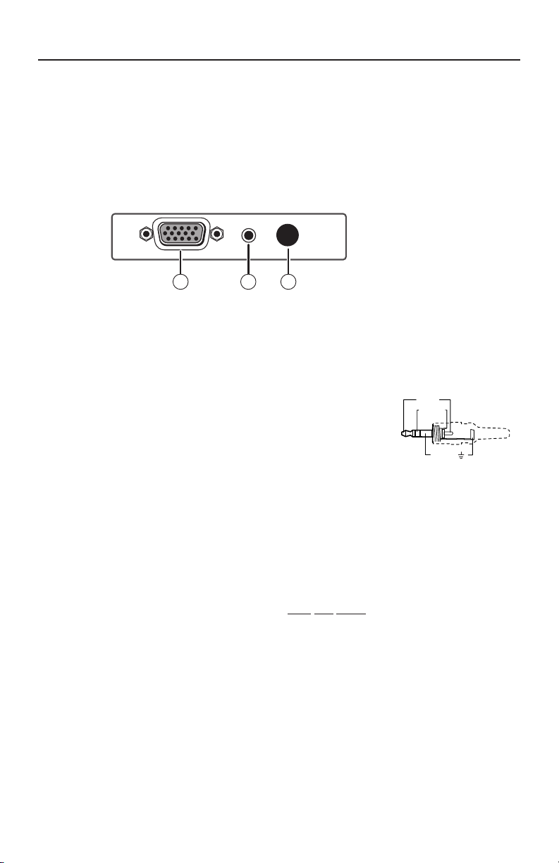
Sleeve ( )
Ring (R)
Tip (L)
3.5 mm Stereo Plug Connector
(unbalanced)
VSW I AAP Interface
The VSW I AAP passive interface features a computer video input and
pass-through, an unbalanced stereo input and pass-through, and an
input select (Show Me) button. All VGA, audio, and control signals are
carried from the rear panel of the AAP to the switcher via a single Extron
VGA/audio cable assembly.
Front panel features
Figure 1 — Front panel features
Computer video input — Input VGA-UXGA, RGBHV, RGBS,
a
RGsB, RsGsBs, component video, or HDTV component video
through this 15-pin female VGA connector.
Audio input — Input unbalanced stereo
b
audio through this 3.5 mm mini audio
jack. See the diagram at right.
Input select (Show Me) button —
c
Pressing this button tells the connected
and compatible switcher to select this
AAP as the switcher's active input.
See "Rear panel features" on the following page.
N
The connected switcher must be compatible with this VGA
pin 5 pull-up control feature. The Extron VSW 2VGA A and
SW VGArs series switchers are compatible with this feature.
Check the user's manuals for these switchers for more detail.
N
N
1 VSW I AAP • Installation and Operation
The show me feature will not work when connected to
SW VGArs series switchers with a circuit board part number of
20-527-0x or 20-935-0x.
Use of the show me feature with specific switchers requires
that jumpers be set in the VSW I AAP. See “Setting
VSW I AAP Jumpers” on page 4.
Page 3

1
2
SW6 VGA Ars
REMOTE
100-240V 0.2A
INPUTS
1
2
3
4
5
50-60Hz
OUTPUT
OUTPUT
L R
SW6 VGA Ars
6
Projector
VSW I
AAP
SW6 VGA Ars
VSW I AAP
COMPUTER
AUDIO
SHOW ME
VSW I
AAP
VSW I AAP
COMPUTER
AUDIO
SHOW ME
VSW I
AAP
VSW I AAP
COMPUTER
AUDIO
SHOW ME
VSW I
AAP
VSW I AAP
COMPUTER
AUDIO
SHOW ME
VSW I
AAP
VSW I AAP
COMPUTER
AUDIO
SHOW ME
VSW I
AAP
VSW I AAP
COMPUTER
AUDIO
SHOW ME
Rear panel features
Figure 2 — Rear panel features
Audio pass-through — Output unbalanced stereo audio through
a
this 3.5 mm mini audio jack. See the previous section's wiring
diagram (b).
Computer video pass-through — Output VGA-UXGA, RGBHV,
b
RGBS, RGsB, RsGsBs, component video, or HDTV component
video through this 15-pin female VGA connector.
Interfacing to SW VGA Series Switchers
The VSW I AAP can be connected to each input of a SW VGArs switcher.
Pressing the Show Me button causes the switcher to select this input.
Refer to the SW VGArs Switchers manual for connection instructions.
Figure 3 — Multiple VSW I AAP inputs to an SW VGArs
switcher
VSW I AAP • Installation and Operation
2
Page 4

Interfacing to a VSW 2VGA A Daisy Chain
In 1
In 2
Extron’s pre-made VGA with audio cable assemblies.
Expandable, economical presentation chain for
conference rooms and library study rooms.
Out
In 2
Extron
VSW 2VGA A
VGA Switcher
In 1
Out
In 2
In 1
Out
Extron
VSW I AAP
Extron
VSW I AAP
Extron’s pre-made
VGA with audio cable
assemblies.
Projector
VSW 2VGA A
INPUT 1
2
1
INPUT 2
VSW 2VGA A
VSW I
AAP
VSW I AAP
COMPUTER
AUDIO
SHOW ME
VSW I AAP
COMPUTER
AUDIO
SHOW ME
VSW 2VGA A
INPUT 1
2
1
INPUT 2
VSW 2VGA A
VSW I
AAP
VSW I AAP
COMPUTER
AUDIO
SHOW ME
VSW 2VGA A
INPUT 1
2
1
INPUT 2
VSW 2VGA A
VSW I
AAP
VSW I AAP
COMPUTER
AUDIO
SHOW ME
VSW 2VGA A
INPUT 1
2
1
INPUT 2
VSW 2VGA A switchers can be daisy chained together to form a
presentation system (figure 4). Each switcher connects to a VSW I AAP.
By pressing the AAP's Show Me button, the user sends a control signal
telling the switcher to select this AAP as the active input. Refer to the
VSW 2VGA A Switchers manual for connection instructions.
Interfacing
Figure 4 — Daisy-chained VSW 2VGA A switchers
VSW I AAP • Installation and Operation
3
Page 5

Configuration
J5
J6
Jumper installed
J6
J5
Switcher compatibility
VSW 2VGA A, board revision C
SW VGArs, board part #20-1118-0x
VSW 2VGA A, board revision A
Setting VSW I AAP Jumpers
A jumper (figure 5) on the VSW I AAP may need to be shifted, from
jumper J6 (the default position) to J5, depending on the switcher to
which the VSW is connected. Refer to the applicable switcher’s manual
to see how to determine the switcher’s board version or level.
Figure 5 — VSW I AAP jumper positions
• If you are daisy chaining with a VSW 2VGA A that has a circuit board
that is revision C or higher, install the jumper on J6.
• If you are daisy chaining with a VSW 2VGA A that has a circuit board
that is revision A, install the jumper on J5.
• If you are daisy chaining with a SW VGArs that has a circuit board
whose part number is 20-1118-0x, install the jumper on J6.
N
The show me feature will not work when connected to
SW VGArs series switchers with a circuit board part number of
20-527-0x or 20-935-0x.
4 VSW I AAP • Installation and Operation
Page 6

Extron Electronics, USA
1230 South Lewis Street
Anaheim, CA 92805
800.633.9876 714.491.1500
FAX 714.491.1517
Extron Electronics, Europe
Beeldschermweg 6C
3821 AH Amersfoort, The Netherlands
+800.3987.6673 +31.33.453.4040
FAX +31.33.453.4050
Extron Electronics, Asia
135 Joo Seng Rd. #04-01
PM Industrial Bldg., Singapore 368363
+800.7339.8766 +65.6383.4400
FAX +65.6383.4664
Extron Electronics, Japan
Kyodo Building, 16 Ichibancho
Chiyoda-ku, Tokyo 102-0082
Japan
+81.3.3511.7655 FAX +81.3.3511.7656
www.extron.com
© 2007 Extron Electronics. All rights reserved.
 Loading...