

Page 1
User’s Guide
VSC 700/900 SDI Output Card
70-065-02 Upgrade Kit
68-735-01 Rev. A
Printed in the USA
09 03
Page 2
Installation
5
0
/
6
0
H
z
1
0
0
-2
4
0
V
0
.3
A
R
/R
Y
R
/R
-
Y
I
N
P
U
T
S
O
U
T
P
U
T
S
G
/Y
2
R
G
B
/R
Y
, Y
,
B
-Y
R
G
B
1
G
/Y
B
/B
-Y
B
/B
-
Y
H
/H
V
H
/H
V
V
V
V
ID
E
O
S
V
I
D
E
O
D
1
R
/
R
Y
G
/Y
B
/B
-Y
H
/
H
Y
R
S
2
3
2
/
4
2
2
G
E
N
L
O
C
K
V
I
N
O
U
T
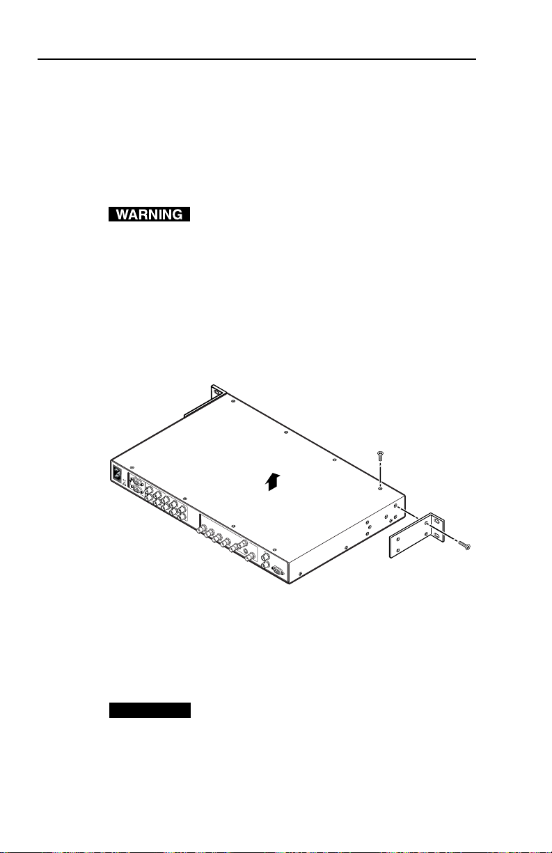
Remove #8 Screw
(4 Plcs) Each Side
and Bracket
Remove (14)
Screws
Lift Cover
straight up
Installing the SDI Ouput Card
The SDI output card may be installed in the VSC 700/900 by
following the instructions and illustrations shown below.
Cover removal
1. Remove the power cable from the VSC and from the power
source.
Do not open the cover of the scan converter without
unplugging the power cord.
2. If the VSC scan converter is rack mounted, detach the input
and output cables from it and remove the unit from the
rack. If the VSC is not rack mounted, you do not need to
remove the input and output cables.
3. Remove 14 screws from the top and sides of the cover
(figure 1) of the VSC 900. The VSC 700 has 12 top and side
cover screws plus 9 rear panel screws and 2 jack screw nuts
(RS-232/422 connector).
Figure 1 — Removing the VSC 900 cover
4. Remove the cover by slightly lifting each side alternately
until the cover is free.
Reverse this procedure to reinstall the cover after the SDI
connector card has been installed.
CAUTION
VSC 700/900 SDI Output Card • Installation
2
Do not touch any switches or other electronic
components inside the VSC. Doing so could damage
the scan converter. Electrostatic discharge (ESD)
can damage IC chips even though you cannot feel it.
You must be electrically grounded. A grounding
wrist strap is recommended.
Page 3

SDI Output Card installation
After following the instructions in “Cover removal” to remove
the cover, do the following:
1. Locate the SDI card standoff located near the middle rear
(VSC 900) or left rear (VSC 700) portion of the main circuit
board (looking from above with the front panel nearest to
you).
SDI card connector opening
SDI card standoff
Figure 2 — SDI card standoff and connector opening
2. Remove the plastic cap covering the SDI connector opening
from the rear panel of the VSC, and position the SDI card at
an angle with the SDI connector protruding from the rear
SDI connector opening.
3. The SDI card has a 20-pin socket on the underside which
must align with the 20 pins on the main circuit board. Be
sure to align the pins properly, in order to prevent bending
the pins, before pressing the SDI card firmly in place against
the standoff. The mounting hole on the SDI card should
now be directly over the standoff.
20-pin socket on
back of SDI card
20-pin connector
on main board
Figure 3 — SDI card situated above pins and standoff
VSC 700/900 SDI Output Card • Installation 3
Page 4

4. Insert the card’s installation screw through the SDI card’s
mounting hole, and gently tighten it into the standoff.
Figure 4 — SDI card mounted in place
5. Install the SDI connector’s hex nut from the outside of the
rear panel opening. Keep the SDI card from twisting as the
nut is tightened.
6. Replace the top cover on the VSC, and fasten it with the
screws which were removed in step 3 of the “Cover
removal” section.
7. Rack/furniture mount the scan converter, and reconnect the
AC power cord.
Part Numbers
Extron Part Part Number
SDI Output Card Kit 70-065-02
Extron Electronics, USA
1230 South Lewis Street
Anaheim, CA 92805
USA
www.extron.com
714.491.1500
Fax 714.491.1517
Extron Electronics, Europe
Beeldschermweg 6C
3821 AH Amersfoort
The Netherlands
+31.33.453.4040
Fax +31.33.453.4050
© 2003 Extron Electronics. All rights reserved.
Extron Electronics, Asia
135 Joo Seng Road, #04-01
PM Industrial Building
Singapore 368363
+65.6383.4400
Fax +65.6383.4664
Extron Electronics, Japan
Daisan DMJ Building 6F
3-9-1 Kudan Minami
Chiyoda-ku, Tokyo 102-0074 Japan
+81.3.3511.7655
Fax +81.3.3511.7656
 Loading...