

Page 1
SMD 101
H.264 Streaming Media Decoder
User Guide
Streaming AV Products
68-2231-01 Rev. A
03 14
Page 2
Safety Instructions
Safety Instructions • English
WARNING: This symbol, , when used on the product, is intended to
alert the user of the presence of uninsulated dangerous voltage within the
product’s enclosure that may present a risk of electric shock.
ATTENTION: This symbol, , when used on the product, is intended
to alert the user of important operating and maintenance (servicing)
instructions in the literature provided with the equipment.
For information on safety guidelines, regulatory compliances, EMI/EMF
compatibility, accessibility, and related topics, see the Extron Safety and
Regulatory Compliance Guide, part number 68-290-01, on the Extron website,
www.extron.com.
Instructions de sécurité • Français
AVERTISSEMENT: Ce pictogramme, , lorsqu’il est utilisé sur le
produit, signale à l’utilisateur la présence à l’intérieur du boîtier du produit
d’une tension électrique dangereuse susceptible de provoquer un choc
électrique.
ATTENTION: Ce pictogramme, , lorsqu’il est utilisé sur le produit,
signale à l’utilisateur des instructions d’utilisation ou de maintenance
importantes qui se trouvent dans la documentation fournie avec le
matériel.
Pour en savoir plus sur les règles de sécurité, la conformité à la réglementation,
la compatibilité EMI/EMF, l’accessibilité, et autres sujets connexes, lisez les
informations de sécurité et de conformité Extron, réf. 68-290-01, sur le site
Extron, www.extron.com.
Sicherheitsanweisungen • Deutsch
WARNUNG: Dieses Symbol auf dem Produkt soll den Benutzer
darauf aufmerksam machen, dass im Inneren des Gehäuses dieses
Produktes gefährliche Spannungen herrschen, die nicht isoliert sind
und die einen elektrischen Schlag verursachen können.
Инструкция по технике безопасности • Русский
ПРЕДУПРЕЖДЕНИЕ: Данный символ, , если указан
на продукте, предупреждает пользователя о наличии
неизолированного опасного напряжения внутри корпуса
продукта, которое может привести к поражению
электрическим током.
ВНИМАНИЕ: Данный символ, , если указан на продукте,
предупреждает пользователя о наличии важных инструкций
по эксплуатации и обслуживанию в руководстве,
прилагаемом к данному оборудованию.
Для получения информации о правилах техники безопасности,
соблюдении нормативных требований, электромагнитной
совместимости (ЭМП/ЭДС), возможности доступа и других
вопросах см. руководство по безопасности и соблюдению
нормативных требований Extron на сайте Extron: www.extron.com,
номер по каталогу - 68-290-01.
Chinese Simplified(简体中文)
警告: 产品上的这个标志意在警告用户该产品机壳内有暴露的危险 电压,
有触电危险。
注意: 产品上的这个标志意在提示用户设备随附的用户手册中有
重要的操作和维护(维修)说明。
关于我们产品的安全指南、遵循的规范、EMI/EMF 的兼容性、无障碍
使用的特性等相关内容,敬请访问 Extron 网站 www.extron.com,参见
Extron 安全规范指南,产品编号 68-290-01。
Chinese Traditional( )
警告: 若產品上使用此符 號,是為了提醒使 用者,產品機殼內存在著
可能會導致觸電之風險的未絕緣危險電壓。
VORSICHT: Dieses Symbol auf dem Produkt soll dem Benutzer in der
im Lieferumfang enthaltenen Dokumentation besonders wichtige Hinweise
zur Bedienung und Wartung (Instandhaltung) geben.
Weitere Informationen über die Sicherheitsrichtlinien, Produkthandhabung,
EMI/EMF-Kompatibilität, Zugänglichkeit und verwandte Themen finden Sie in
den Extron-Richtlinien für Sicherheit und Handhabung (Artikelnummer
68-290-01) auf der Extron-Website, www.extron.com.
Instrucciones de seguridad • Español
ADVERTENCIA: Este símbolo, , cuando se utiliza en el producto,
avisa al usuario de la presencia de voltaje peligroso sin aislar dentro del
producto, lo que puede representar un riesgo de descarga eléctrica.
ATENCIÓN: Este símbolo, , cuando se utiliza en el producto, avisa
al usuario de la presencia de importantes instrucciones de uso y
mantenimiento recogidas en la documentación proporcionada con el
equipo.
Para obtener información sobre directrices de seguridad, cumplimiento
de normativas, compatibilidad electromagnética, accesibilidad y temas
relacionados, consulte la Guía de cumplimiento de normativas y seguridad de
Extron, referencia 68-290-01, en el sitio Web de Extron, www.extron.com.
注意 若產品上使用此符號,是為了提醒使用者,設備隨附的用戶手冊中有重
要的操作和維護(維修)説明。
有關安全性指導方針、法規遵守、EMI/EMF 相容性、存取範圍和相關主題的詳細資
訊,請瀏覽 Extron 網站:www.extron.com,然後參閱《Extron 安全性與法規
遵守手冊》,準則編號 68-290-01。
Japanese
警告: この記号 が製品上に表示されている場合は、筐体内に絶縁されて
いない高電圧が流れ、感電の危険があることを示しています。
注意: この記号 が製品上に表示されている場合は、本機の取扱説明書
に 記載さ れて いる重 要な操 作 と保 守 ( 整 備)の 指 示につ いてユーザ ー の 注
意を喚起するものです。
安全上のご注意、法規厳守、EMI/EMF適合性、その他の関連項目に
つ い て は 、エ ク スト ロン の ウ ェ ブ サ イト www.extron.com よ り 『 Extron Safety
and Regulatory Compliance Guide』 ( P/N 68-290-01) をご覧ください。
Korean
경고: 이 기호 가 제품에 사용될 경우, 제품의 인클로저 내에 있는
접지되지 않은 위험한 전류로 인해 사용자가 감전될 위험이 있음을
경고합니다.
주의: 이 기호 가 제품에 사용될 경우, 장비와 함께 제공된 책자에 나와
있는 주요 운영 및 유지보수(정비) 지침을 경고합니다.
안전 가이드라인, 규제 준수, EMI/EMF 호환성, 접근성, 그리고 관련 항목에
대한 자세한 내용은 Extron 웹 사이트(www.extron.com)의 Extron 안전 및
규제 준수 안내서, 68-290-01 조항을 참조하십시오.
Page 3

FCC Class A Notice
This equipment has been tested and found to comply with the limits for a Class A digital device,
pursuant to part15 of the FCC rules. The ClassA limits provide reasonable protection against harmful
interference when the equipment is operated in a commercial environment. This equipment generates,
uses, and can radiate radio frequency energy and, if not installed and used in accordance with the
instruction manual, may cause harmful interference to radio communications. Operation of this
equipment in a residential area is likely to cause interference; the user must correct the interference at
his own expense.
NOTE: For more information on safety guidelines, regulatory compliances,
EMI/EMF compatibility, accessibility, and related topics, see the
“Extron Safety and Regulatory Compliance Guide” on the Extron website.
Copyright
© 2014 Extron Electronics. All rights reserved.
Trademarks
All trademarks mentioned in this guide are the properties of their respective owners.
The following registered trademarks®, registered service marks
(SM)
, and trademarks
(TM)
are the property of
RGBSystems, Inc. or Extron Electronics:
Registered Trademarks
AVTrac, Cable Cubby, CrossPoint, eBUS, EDID Manager, EDID Minder, Extron, Flat Field, GlobalViewer, Hideaway, Inline, IPIntercom,
IPLink, Key Minder, LockIt, MediaLink, PlenumVault, PoleVault, PowerCage, PURE3, Quantum, SoundField, SpeedMount, SpeedSwitch,
SystemINTEGRATOR, TeamWork, TouchLink, V-Lock, VersaTools, VN-Matrix, VoiceLift, WallVault, WindoWall, XTP, and XTP Systems
Registered Service Mark
AAP, AFL (Accu-Rate Frame Lock), ADSP (Advanced Digital Sync Processing), Auto-Image, CDRS (Class D Ripple Suppression), DDSP (Digital
Display Sync Processing), DMI (Dynamic Motion Interpolation), DriverConfigurator, DSPConfigurator, DSVP (Digital Sync Validation Processing),
FastBite, FOXBOX, IP Intercom HelpDesk, MAAP, MicroDigital, ProDSP, QS-FPC (QuickSwitch Front Panel Controller), Scope-Trigger, SIS,
Simple Instruction Set, Skew-Free, SpeedNav, Triple-Action Switching, XTRA, ZipCaddy, ZipClip
(SM)
: S3 Service Support Solutions
Trademarks (™
(®)
)
Page 4
Conventions Used in this Guide
Notifications
The following notifications are used in this guide:
CAUTION: A caution indicates a situation that may result in minor injury.
ATTENTION: Attention indicates a situation that may damage or destroy the product or
associated equipment.
NOTE: A note draws attention to important information.
TIP: A tip provides a suggestion to make working with the application easier.
Software Commands
Commands are written in the fonts shown here:
^AR Merge Scene,,Op1 scene 1,1 ^B 51 ^W^C
[01] R 0004 00300 00400 00800 00600 [02] 35 [17] [03]
E X! *X1&* X2)* X2#* X2! CE}
NOTE: For commands and examples of computer or device responses mentioned
in this guide, the character “0” is used for the number zero and “O” is the capital
letter “o.”
Computer responses and directory paths that do not have variables are written in the font
shown here:
Variables are written in slanted form as shown here:
Selectable items, such as menu names, menu options, buttons, tabs, and field names are
written in the font shown here:
Specifications Availability
Product specifications are available on the Extron website, www.extron.com.
Reply from 208.132.180.48: bytes=32 times=2ms TTL=32
C:\Program Files\Extron
ping xxx.xxx.xxx.xxx —t
SOH R Data STX Command ETB ETX
From the File menu, select New.
Click the OK button.
Page 5

Contents
Introduction .................................................... 1
About this Guide ................................................. 1
About the SMD101 ............................................ 1
Video Output .................................................. 3
Output Resolution and EDID Support Table ... 4
Suggested PC Requirements .......................... 5
Supported formats: ........................................ 5
Features ............................................................. 6
Panels and Cabling ......................................... 8
Front Panel Features ........................................... 8
Rear Panel Features ........................................... 9
SMD101 Rear Panel Reset .......................... 12
SMD101 Power Up Procedure ........................ 13
Hardware Setup Overview ................................ 13
Web-based User Interface ...........................14
Overview of the Web-based User Interface ....... 14
Accessing the Web-based User Interface ......... 14
Page Overview ................................................. 15
Player Page ...................................................... 16
Player Controls ............................................ 16
Browser ........................................................ 18
Browser Panel - Streams .............................. 19
Browser Panel - Files .................................... 20
Lists.............................................................. 22
Playlist Editor ................................................ 25
Configuration Page ........................................... 28
Video Configuration ...................................... 28
Audio Configuration ...................................... 30
On Screen Display ........................................ 31
Automation ................................................... 32
Advanced Configuration Page .......................... 34
Connection .................................................. 34
Firmware Loader ........................................... 36
Exec/Power Mode ........................................ 39
Date and Time .............................................. 40
Password ..................................................... 40
Reset Device ................................................ 42
SNMP ........................................................... 43
Device Information Page ................................... 44
Status Page ...................................................... 45
Browser Idle ..................................................... 47
Advanced Player Configuration ................... 48
Loading Content to Local Storage
Using SFTP ..................................................... 48
Play Video on Demand ..................................... 51
Play Video from a Network Share ................. 51
SME100 Stream Discovery .............................. 53
Connecting to Streams Without SAP
Announcements .............................................. 54
UDP or RTP Connections ............................. 54
HTTP Connection to an SME100 ................. 54
IR Remote Control ........................................ 56
Remote Communication and Control .......... 57
Connection Options .......................................... 57
RS-232 Port ................................................. 57
Front Panel Configuration Port ...................... 58
LAN (Ethernet) Port........................................... 59
Verbose Mode .............................................. 60
Host-to-device Communications ...................... 61
SMD101-initiated Messages ........................ 61
Password Information ................................... 61
Using the Command and
Response Tables ......................................... 61
Error Responses ........................................... 62
Simple Control Port Commands - Telnet
and Web-browser Accessible ...................... 63
Command and Response Tables ...................... 67
Basic SIS Commands ................................... 67
Player SIS Commands .................................. 74
SMD101 • Contents v
Page 6

Reference Information ................................. 81
Parts and Accessories ...................................... 81
Mounting the SMD101 .................................... 81
Tabletop Use ................................................ 81
Rack Mounting ............................................. 82
Furniture Mounting........................................ 82
Table or Wall Mounting .................................. 82
SMD101 Reset Summary ................................ 83
Optimum Network Share Performance ............. 85
Network Shares Dialog ................................. 85
Configuring Windows 7 for
Network File Sharing ....................................... 86
Copying Config Files Using Internet Explorer ..... 92
DataViewer ....................................................... 93
Glossary ........................................................... 94
SMD101 • Contents vi
Page 7

Introduction
This section gives an overview of the user guide and describes the SMD101 and its
features. Topics that are covered include:
• About this Guide
• About the SMD101
• Features
About this Guide
This guide contains installation, configuration, and operating information for the SMD101.
In this guide:
• Codec or H.264 refers to the H.264/MPEG-4 Part 10 AVC codec.
• Stream can refer to audio, video, or both that is received by the SMD101 and
constantly decoded for display.
About the SMD101
The SMD101 is a compact, high performance H.264 decoder used in applications that
require live AV streaming or file playback from files located on other network devices and
shared. The SMD101 can decode and display one SD or HD stream and output a single
HDMI signal supporting resolutions up to 1920x1200 (60 fps, progressive). The video output
can be scaled and its aspect ratio modified. The Extron SMD101 is compatible with all
SME100 HD and SD encoder streaming protocols and resolutions.
The SMD101 can be controlled using IR, RS-232, or Ethernet. Ethernet to RS-232
pass-through for display control is possible.
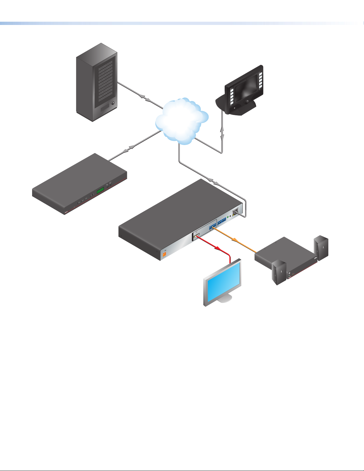
The SMD101 decodes H.264/MPEG-4 AVC streams or clips and outputs HDMI video with
embedded audio for display on any HDMI compatible device (see figure 1 on the next page).
SMD101 • Introduction 1
Page 8
Sound System
b
Extron
SME 100
Streaming
Encoder
Network Attached
a
Storage
VCR
DVD
DOC
CAM
LAPTOP
ON
OFF
DISPLAY
MUTE
SCREEN
UP
SCREEN
DOWN
PC
Extron
Extron
TLP 700TV
Touch Panel
Select:
Internet/
Network
SME 100
CODER
EDIA EN
STREAMING M
ADJUST
MENU NEXT
3
2
1
CONFIG
Local Storage
c
(internal)
HDMI
OUTPUTS
Ethernet
RESET
LAN
RS-232
IR IN
Tx Rx G
AUDIO
S G
L R
Audio
a NAS
b Stream
c
Local
Extron
SI 26
Surface-mount
Speakers
POWER
12V
--A MAX
Extron
SMD 101
Streaming
Media Decoder
HDMI/RGB
2
XPA 100
ER/PROTECT
2
1
LIMIT
SIGNAL
VER
O
EMP
T
Extron
XPA 1002
Stereo Power
Amplier
HD Display
HDMI/RGB/Analog
Figure 1. Typical SMD101 Application
SMD101 • Introduction 2
Page 9

Video Output
The SMD101 can decode and display one SD or HD stream. The optional handheld
IR remote control allows channel preset recall and channel navigation. The SMD101
automatically detects transport and stream formats and decodes the content for
presentation to the display.
A channel list can be defined that allows simple selection of individual streams. The user can
import or export source selection data including URLs and associated data from the channel
list. This is an extension of the configuration save or restore capability that can save box and
IP configuration settings for the product as a separate xml file.
The channel list can be accessed with a remote control (not included) for selection and
playing streams included in the list.
The SMD101 decodes all common stream resolutions and frame rates.
NOTES: The SMD101 does not support decoding of encrypted content.
The SMD101 can be configured using a host PC or laptop connected to the front
panel USB Config port, the RJ-45 LAN connector, or the RS-232 port (see Remote
Communication and Control on page57). A compatible web browser on a control PC
connected to the same network as the SMD101 can access the embedded HTML pages.
A video confidence display allows image monitoring from the user interface while making
configuration and control adjustments.
Video output parameters are configured automatically for the connected display based
on the display EDID, or can be configured manually using a browser and the video
configuration page.
NOTE:
• The SMD101 does frame rate conversion between the input stream frame rate
and the output frame rate, scaling from the source resolution and output resolution,
and aspect ratio between fit (zoom), fill, and follow as required.
• Fill and follow background, when necessary, is black.
The SMD101 by default, automatically outputs video corresponding to EDID data from the
connected display within the resolution and rate combinations (see Output Resolution and
EDID Support Table on page4). The output rates available are limited by the display
capabilities. EDID data exchange is compatible with E-EDID V2.0 (EDID data structure 1.4)
and EIA/CEA-861E.
SMD101 • Introduction 3
Page 10
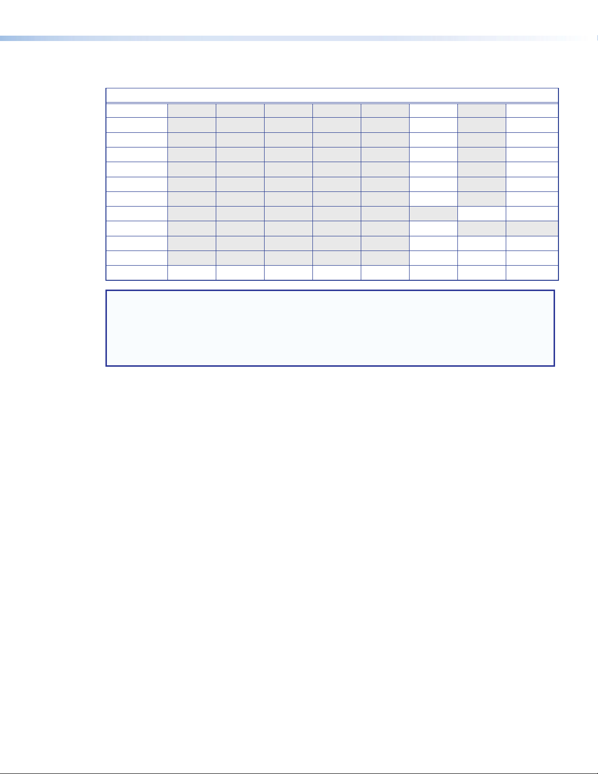
Output Resolution and EDID Support Table
Resolution 23.98 Hz 24 Hz 25 Hz 29.97 Hz 30 Hz 50 Hz 59.94 Hz 60 Hz
640x480 10 11
800x600 12 13
1024x768 14 15
1280x1024 16 17
1366x768 18 19
1600x1200 20 21
1920x1200 22 23*
480p 24 25
576p 26
720p 32 33 34 (default)
1080i 35 36 37
1080p 38 39 40 41 42 43 44 45*
NOTES:
• Numbers indicate the EDID preset resolution.
• * With reduced blanking.
• Highest resolution is 1920x1200 (158.25 MHz@50 Hz and 154 MHz@60 Hz*).
• Highest pixel rate is 1600x1200 @ 60 Hz (162 MHz).
For applications where the EDID settings do not provide or allow the desired results, select
a video output from the table. Select a defined output rate combination supported by the
display, or set the video output to match the input stream.
The output is muted automatically after a defined period of inactivity. Alternately, it is muted
and unmuted under user control. Video mute settings are cleared during reboot or power
cycle events (see Configuration Page on page28).
SMD101 • Introduction 4
Page 11

Suggested PC Requirements
The suggested PC requirements to access the default web pages of the SMD101 are listed
below.
• Hardware
• 2.0 GHz dual-core processor
• Operating Systems
• Microsoft
• Mac
®
Windows® XP or higher
®
OS® X® 10.6 or higher
• Web Browsers
• Google
• Mozilla
• Internet Explorer
• Apple
®
Chrome™ (version 21 or higher)
®
Firefox® (version 15 or higher)
®
Safari® version 8 or higher (for Mac OS X operating systems)
Supported formats:
• File Formats
• MPEG2 TS MPEG-2 part 1 (or ISO/IEC 13818-1 or ITU-T Rec. H.222.0)
• MP4 (including mp4, m4a, m4v file extensions, not case sensitive).
• TS, m2t, m2ts, 264, and sdp.
• MOV and FLV (supports only files that use H.264 encoding and AAC audio)
• Streaming Container Formats
• MPEG2 Transport stream (including .ts, .m2ts, .m2t file extensions, not case
sensitive)
®
version 8 or higher (for Windows operating systems)
NOTE: Adaptive bit rate streams are not supported.
The SMD101 can play video on demand from network shares and local storage supporting
the following file types:
Video: mp4, ts, m2t, m2ts, mov*, 264, m4v, flv*, and sdp.
NOTE: *Supports files that use H.264 encoding and AAC audio only.
Images: bmp, jpg, jpeg, tif, tiff, png, and gif.
NOTE: TIFF files using JPEG compression are not supported.
Audio: wav, aac, and m4a.
Playlists: jspf, m3u, m3u8, pls, and xspf.
SMD101 • Introduction 5
Page 12

Features
• Supports live IP video stream decoding — Combine with the SME100 to provide a
complete end-to-end streaming solution.
• Supports streaming resolutions from 480x320 up to 1080p/60 — Supports a wide
range of resolutions to meet varying network conditions, topologies, source and display
requirements.
• AV media file playback from network shares — Use as a playback device for
on-demand playback of network-accessible media files.
• Compatible with MP4 and MPEG-2 Transport Stream container formats —
Playback common H.264 media player formats from accessible network drives.
• Stereo or dual mono audio output format: Embedded HDMI digital audio or
analog stereo audio — Flexible, cost effective use of display speakers or existing
audio systems.
• Integrated scaler offers selectable output resolutions from 640x480 to
1920x1200 — Wide range of output resolutions ensure that consistent, reliable image
quality is presented on many different types of displays.
• Decode at native resolution — The output rate and resolution can be configured to
automatically follow the native format of the connected display.
• EDID defined scaling — The output rate and resolution can be configured for
automatic selection based on EDID communication with the connected display.
• Ethernet to RS-232 pass through control — Integration friendly Ethernet to RS-232
pass through for display control.
• Fill/Follow/Fit (zoom) Aspect Ratio Management — Decoded video can fill a
display, maintain aspect ratio, or maintain uniformity, presenting imagery that meets
customer expectations.
• Control from IR remote, wired IR, RS-232, Ethernet, or embedded web
interface— Select from a range of control options to manage the SMD 101 for
stand-alone operation or as part of an AV system.
• Compatible with the full range of SME 100 streaming transport protocols—
Providing the flexibility to apply the most appropriate protocol based on various
streaming system requirements and network conditions.
• Compatible with unicast and multicast push, or pull streaming applications—
Support for push and pull streaming makes the SMD 101 compatible with different
network topologies and streaming system configurations.
• Upload and display image files — Upload PNG, JPG, TIFF (TIFF with JPEG
compression not supported), or BMP image files at resolutions up to 1920x1080 to
present familiar imagery or organizational branding, either on demand or in times of
network or streaming disruption.
• On-screen messaging — On-screen presentation of operating status or channel
selection aids in channel selection, system configuration, and troubleshooting.
• HDMI output — Compatible with HDMI and DVI digital displays.
• Automatic negotiation of streaming transport protocols with SME 100 —
Makes configuration and operation of Extron H.264 streaming products easy in various
streaming and network configurations.
• Easy-to-use embedded web interface — Embedded web interface makes
configuration and deployment a simple activity.
SMD101 • Introduction 6
Page 13

• Playback controls including progress bar — On-screen playback controls present a
visual indication of Time and Pause status, allowing for efficient control of content.
• Compatible with many third party H.264 encoders — Decode 720p/60 and
1080p/60 streaming video from an Extron SME100 or other compatible H.264
encoders.
• Compatible with H.264 Baseline, Main, and High profiles up to and including
level 4.2 — Offers the flexibility to efficiently decode and present streaming video at
various bit rates and coding complexity.
• Decoder status reporting — Simplify configuration and troubleshooting activities with
on-screen status reporting to ensure continuous, reliable operation.
• Front-accessible USB configuration port — Front-accessible port provides easy
access for system configuration and control from a PC.
• Compact and energy efficient — Efficient, low power use generates very little heat,
making it easy to optimize rack space and maintain lower operating costs.
SMD101 • Introduction 7
Page 14
Panels and Cabling
This section provides information on:
• Front Panel Features
• Rear Panel Features
• SMD101 Power Up Procedure
• Hardware Setup Overview
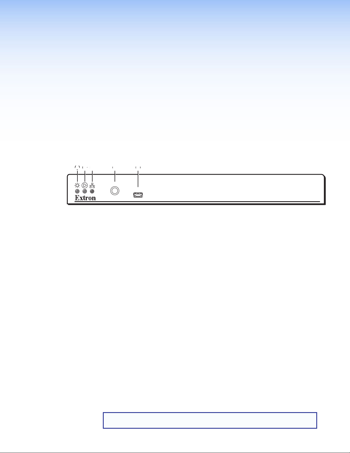
Front Panel Features
The front panel of the SMD101 is shown in figure 2 below.
AABBCCDDEE
IR
Power LED
A
Playback status indicator
B
Network status indicator
C
Figure 2. SMD101 Front Panel
Power LED — Dual color LED lights solid green when the SMD101 is powered. Lights
A
solid red when standby mode is active.
Playback status indicator — Dual color LED indicates playback operation:
B
• Solid Green — The SMD101 is actively decoding a source (clip, image, or
stream).
• Blinking Green — A source (clip, image, or stream) is loaded but paused.
• Off — Playback has stopped.
• Solid Red — Unable to load (or play) the selected source.
Network status indicator — Dual-color LED indicates network operation and
C
connection or stream quality:
• Solid Green — Indicates network conditions are favorable for the current source.
The LED is also green if the current source is a local file (see Browser Panel -
Files on page20).
• Red/Green — When flashing red and green, indicates encoder or network
conditions could compromise image or audio quality, and buffers could be
depleted.
• Red — When lit, indicates degraded server or network conditions are
compromising video or audio quality and may have depleted the buffers.
• Off — No network connection.
CONFIG
IR receiver window
D
Config port
E
SMD 101
NOTE: In many cases, the error correction features of the SMD101 allow good
image quality even when degraded network conditions are indicated.
SMD101 • Panels and Cabling 8
Page 15
IR Receiver Window— Allows remote operation using an optional compatible IR hand
D
control.
Config port — Connect a control PC or other USB device to this port using a
E
mini-B USB cable (not supplied). Use this port to send Simple Instruction Set (SIS)
commands to the SMD101 for device configuration and control.
• For information on connecting a control PC or other USB device to this port, see
• For information on SIS commands, see Remote Communication and Control on
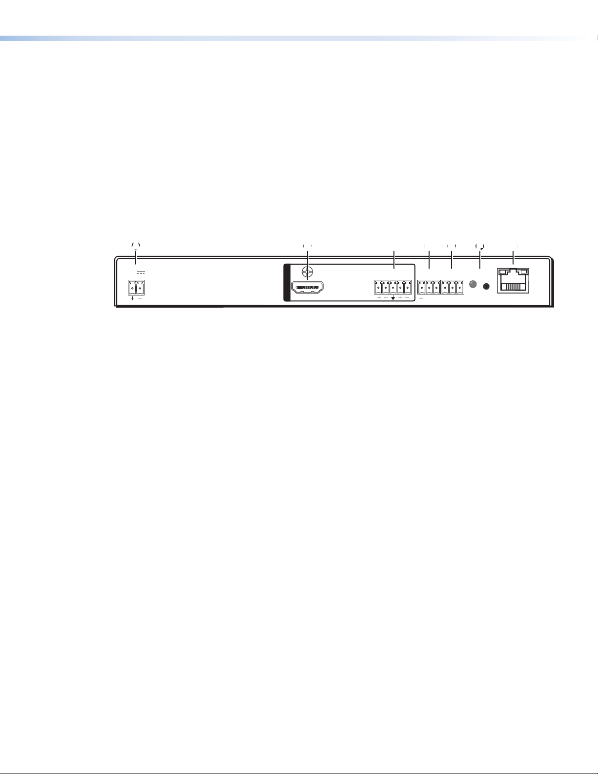
Rear Panel Features
The rear panel of the SMD101 is shown in figure 3 below.
the Front Panel Configuration Port section on page 58.
page 57.
AB
POWER
12V
1.0A MAX
12 VDC Power connector
A
HDMI output connector
B
Analog audio output connector
C
IR input connector
D
BCCDDEEFF
OUTPUTS
HDMI
AUDIO
LR
RS-232 connector (optional)
E
Reset button and LED
F
RJ-45 LAN connector
G
IR IN
SG
RS-232
Tx Rx G
RESET
GGA
LAN
Figure 3. SMD101 Rear Panel
SMD101 • Panels and Cabling 9
Page 16
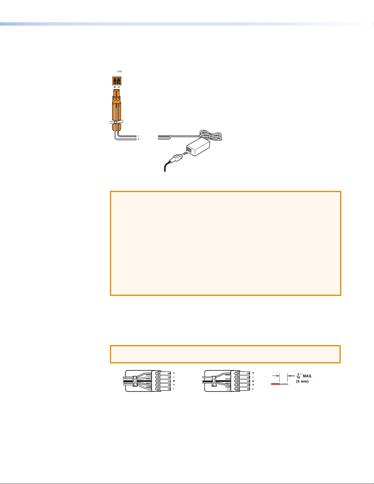
12 VDC power input — Connect the provided 12VDC power supply to the rear panel
y
)
POWER
Balanced Audio Output
Slee
Unbalanced Audio Output
Do not tin the wires!
A
captive screw connectors. When power is connected, the front panel power indicator
lights green (see figure 2, A on page 8).
12V
1.0A MAX
Rear Panel
Power Receptacle
Ground
+12 VDC
External
Power Suppl
AC Power Cord
(12 VDC, 1 A
Figure 4. Power Supply Connection
ATTENTION:
• Always use a power supply provided by or specified by Extron. Use of an
unauthorized power supply voids all regulatory compliance certification and
may cause damage to the supply and the end product.
• Unless otherwise stated, the AC/DC adapters are not suitable for use in air
handling spaces or in wall cavities. The power supply is to be located within the
same vicinity as the Extron AV processing equipment in an ordinary location,
Pollution Degree 2, secured to the equipment rack within the dedicated closet,
podium, or desk.
• The installation must always be in accordance with the applicable provisions of
National Electrical Code ANSI/NFPA 70, article 725 and the Canadian Electrical
Code part 1, section 16. The power supply shall not be permanently fixed to
building structure or similar structure.
HDMI output connector — One female HDMI to connect a display or other HDMI
B
output device.
Audio output connector — Connect audio output devices using cables with balanced
C
or unbalanced 3.5mm, 5-pole captive screw connectors. See figure 5 below to wire the
connectors.
ATTENTION: For unbalanced audio, connect the sleeves to the ground contact.
DO NOT connect the sleeves to the negative (–) contacts.
Tip
Ring
ves
Tip
Ring
Figure 5. Audio Output Captive Screw Connector Wiring
LR
Tip
Sleeves
Tip
LR
SMD101 • Panels and Cabling 10
Page 17
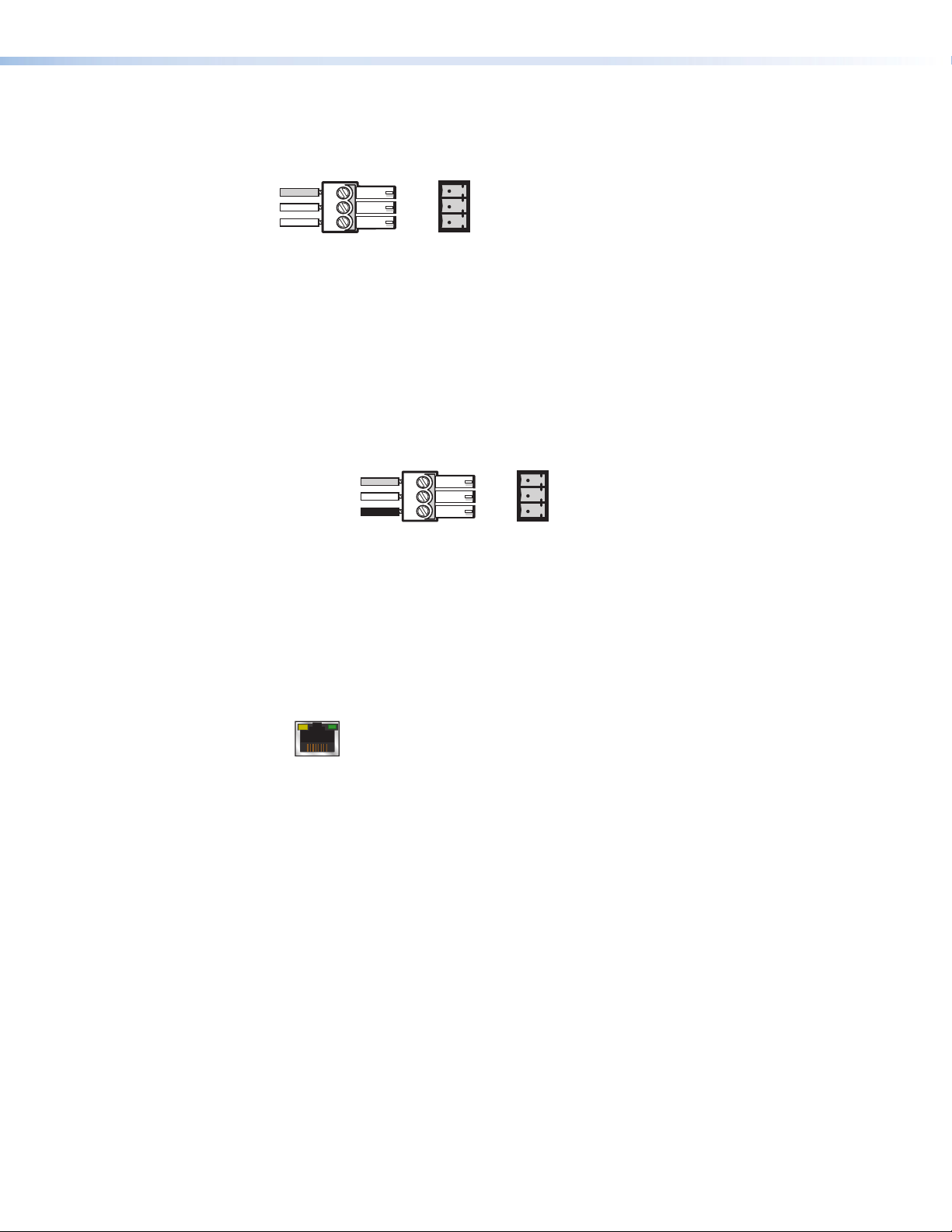
IR IN — Connect a remote IR receiver to this 3-pole 3.5 mm captive screw connector
From
SMD 101
Connected RS-232
SMD 101
LAN
ACTLINK
D
to extend the range of the hand control.
IR Receiver
IR IN
+
S
G
Figure 6. IR In Wiring
RS-232 connector (optional) — Connect a host computer or control system to the
E
RS-232 connector or to the local device if pass-through mode is used. Use this port to
send SIS commands to the SMD101 for device configuration and control. The default
protocol for this port is 9600 baud rate, no parity bit, 8 data bits, 1 stop bit, and no flow
control (handshaking).
• For information on SIS commands, see Remote Communication and Control on
page57.
• See figure 7 below, to wire the RS-232 connector.
Device Pins
Receive
Transmit
Ground
Pins
Tx
Rx
G
Figure 7. RS-232 Connector Wiring
Reset button and LED — The reset button is used to return the SMD101 to partial
F
or complete factory condition. The reset LED provides the status of the reset. The
SMD101 has three reset modes (see SMD101 Rear Panel Reset on the following
page).
RJ-45 LAN connector — Connect one end of an RJ-45 cable to the LAN (Ethernet)
G
connector on the SMD101 (see figure 8). Connect the other end of the RJ-45 cable to
a router or switch to connect the SMD101 to a network.
Figure 8. RJ-45 Ethernet Connector
The LEDs on the Ethernet connector indicate the status of the network connection.
• Link LED — This green LED lights when the SMD101 is properly connected to an
active network.
• Act LED — This amber LED blinks in a pattern to indicate the connected network
speed as follows:
• Three blinks — 1 Gbps
• Two blinks — 100 Mbps
• One blink — 10 Mbps
SMD101 • Panels and Cabling 11
Page 18
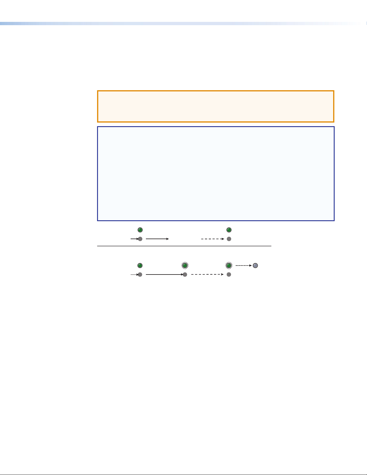
SMD101 Rear Panel Reset
Modes 4 and
Mode 1
Press and
6 or 9 seconds
The Reset button on the rear panel of the SMD101 (see Figure 3 on page9) returns the
SMD101 to various modes of operation.
To select different reset modes, use a pointed stylus or small screwdriver to press and hold
the Reset button while the SMD101 is powered, or press and hold the Reset button while
applying power to the SMD101.
ATTENTION: Review the reset modes carefully. Some reset modes delete all
user loaded content and revert the device to default configuration. The SMD101
Reset Summary on page83 provides a summary of the reset modes and the
configuration settings affected by each mode.
NOTES:
• The reset modes close all open IP and Telnet connections and all sockets.
• Each reset mode is a separate reset (not a continuation from mode 1 to mode 5).
• Reset modes 2 and 3 are not available for the SMD101.
• The SMD101 can also be reset using the web-based user interface (see Reset
Device on page42).
• For information on resetting the SMD101 using SIS commands, see Resets on
page68 of the Command and Response Tables section.
• Further details comparing the reset modes and affected configuration settings
and user content are in the reference section (see SMD101 Reset Summary on
page83).
Press and hold
the Reset button.
5
hold for
.
RESET
RESET RESET
Apply power
to the SMD 101.
Reset LED flashes
twice or three times.
RESET
Release Reset button.
Release, then immediately
press and release again. Reset
LED flashes, then goes off.
RESET
Figure 9. Resetting the SMD101
SMD101 • Panels and Cabling 12
Page 19

SMD101 Power Up Procedure
NOTE: Before powering on the SMD101, ensure that all necessary devices are
connected properly. Devices do not need to be powered.
Connect the external power supply to a 100 to 240 VAC supply (see Rear Panel Features
on page9). The DC power LED lights and the SMD101 undergoes a self testing
sequence. When connected to a network, the front panel network LED indicator lights green
when the SMD101 is ready to decode.
Hardware Setup Overview
NOTE: If it is difficult to access the device after installation, configure the network
settings of the SMD101 prior to starting (see Accessing the Web-based User
Interface on page14 , and Connection on page34).
1. If the SMD101 has been on for configuration, turn it off and disconnect the SMD101
and all connected devices.
2. Mount the SMD101 (see Mounting the SMD101 on page81).
3. Connect one end of an RJ-45 cable to the rear panel LAN connector on the SMD101
(see Rear Panel Features on page9). Connect the other end of the RJ-45 cable
to the local network.
4. Connect a compatible output device to the rear panel (see Rear Panel Features on
page9) and power it on.
5. Connect a control device to the SMD101 by one of the following connections:
a. The front panel config port (see Front Panel Configuration Port on page58).
b. The rear panel RS-232 port (see RS-232 Port on page57).
c. The Ethernet connection. Configure the network settings of the control PC so it is
compatible with the network the SMD101 is connected to (see LAN (Ethernet)
6. Connect the external power supply output connector to the SMD101 (see Rear Panel
7. From the control PC, access the user interface of the SMD101 (see Accessing the
8. Select a stream to decode (see Player Page on page16).
9. If necessary, set the decoder output for the connected display (see Video Output on
10. Press Play on the software interface (see Player Page on page16) or on the
Port on page59).
Features on page9), then connect the power supply to a 100 to 240 VAC, 50 Hz
or 60 Hz power source. The SMD101 powers up automatically and undergoes a self
testing sequence (see the SMD101 Power Up Procedure, above).
Web-based User Interface on page14).
page3 and Video Configuration on page28).
optional remote control (see IR Remote Control on page56) to begin decoding the
selected stream.
SMD101 • Panels and Cabling 13
Page 20
Web-based User Interface
This section provides information about:
• Overview of the Web-based User Interface
• Accessing the Web-based User Interface
• Page Overview
• Player Page
• Configuration Page
• Advanced Configuration Page
• Device Information Page
• Status Page
• Browser Idle
Overview of the Web-based User Interface
The web-based user interface, accessed from a control device, can configure, remotely
control, monitor, update firmware, and operate the SMD101.
NOTE: Google Chrome was used to take the SMD101 user interface screen shots in
this user guide and is the recommended browser. Pages and panels viewed in other
browsers may not appear exactly the same.
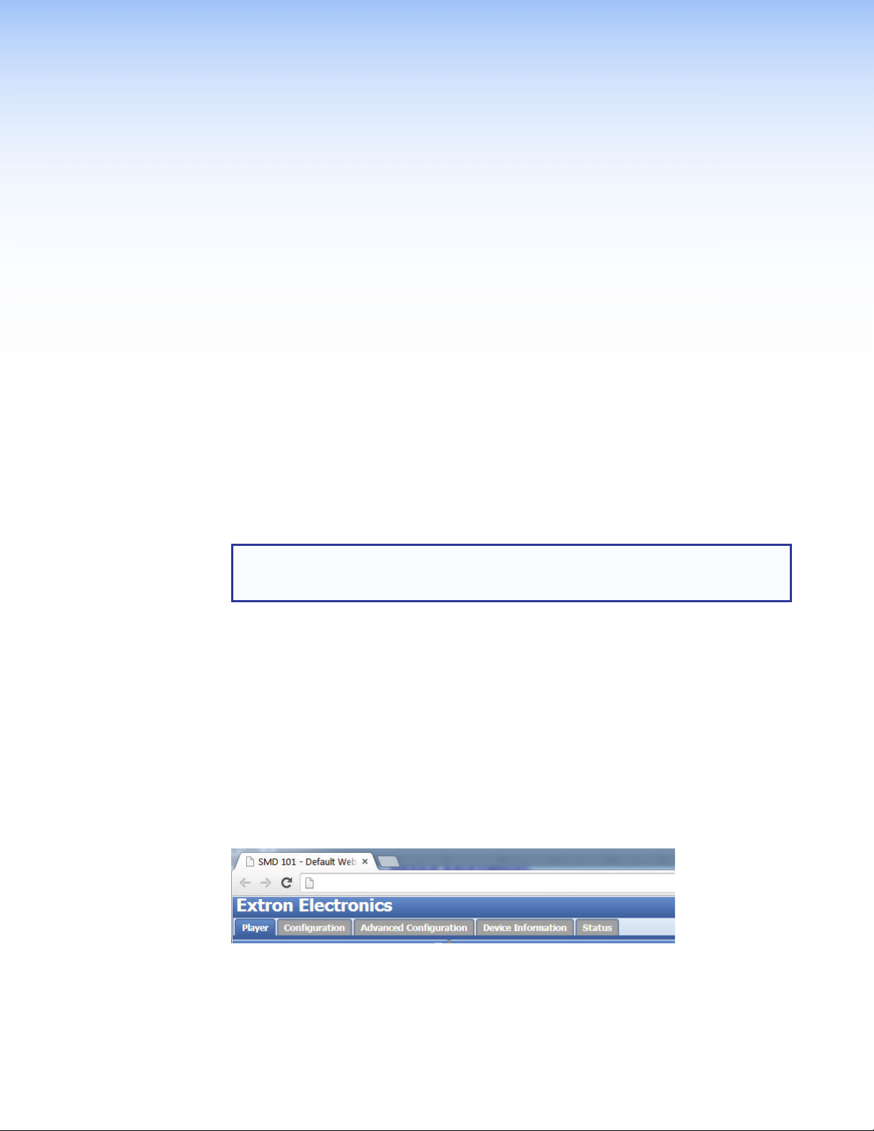
Accessing the Web-based User Interface
To access the web-based user interface, connect a control PC or viewing device to the
SMD101 and open a compatible web browser. Enter the IP address of the SMD101
(default IP address is 192.168.254.254) into the browser address bar.
There are five pages with related controls grouped together on each page:
• Player — used to select the source (stream) and control decoding.
• Configuration — provides basic user level adjustments.
• Advanced Configuration — for initial setup and administrator use.
• Device Information — provides default setting and user defined information.
• Status — Real-time display of operating conditions and statistics.
Access pages by selecting the tab across the top of the dialog box.
http://192.168.254.254/www/
Figure 10. Web-based User Interface, Page TabsBrowser Idle
To conserve the host PC resources, after 60 minutes, the browser accessing the SMD101
web interface stops requesting status and video confidence updates.
This feature does not idle or affect SMD101 operation. It suspends the automatic browser
updates for the video confidence display to conserve network and PC resources. Press
Resume to force the browser to reconnect to the SMD101 and begin normal updates.
SMD101 • Web-based User Interface 14
Page 21
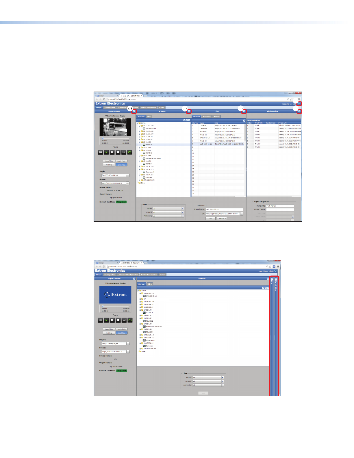
Page Overview
The web interface opens as shown in figure 11 (below). The page contains multiple panels
that are collapsed and expanded using the buttons at the top of each panel
(see figure 11, 1 and 2).
An interactive embedded help file is always available by clicking the help icon
(see figure 11, 3) from any page or panel.
33
3
2
11
22
2
2
22
22
Figure 11. Player Page - All Panels Open
The Browser, Lists, and Playlist Editor panels can be collapsed or resized horizontally
to provide additional space for other page information and details. The Player Controls
panel can only be collapsed or expanded. Its size, when open, is fixed.
Figure 12. Player Page - Browser and Playlist Editor Collapsed
In figure 12, the Lists, and Playlist Editor panels are collapsed. The Player Controls
panel remains the same size while the Browser panel expands to fill the screen space
previously occupied by the Lists and Playlist Editor panels.
SMD101 • Web-based User Interface 15
Page 22
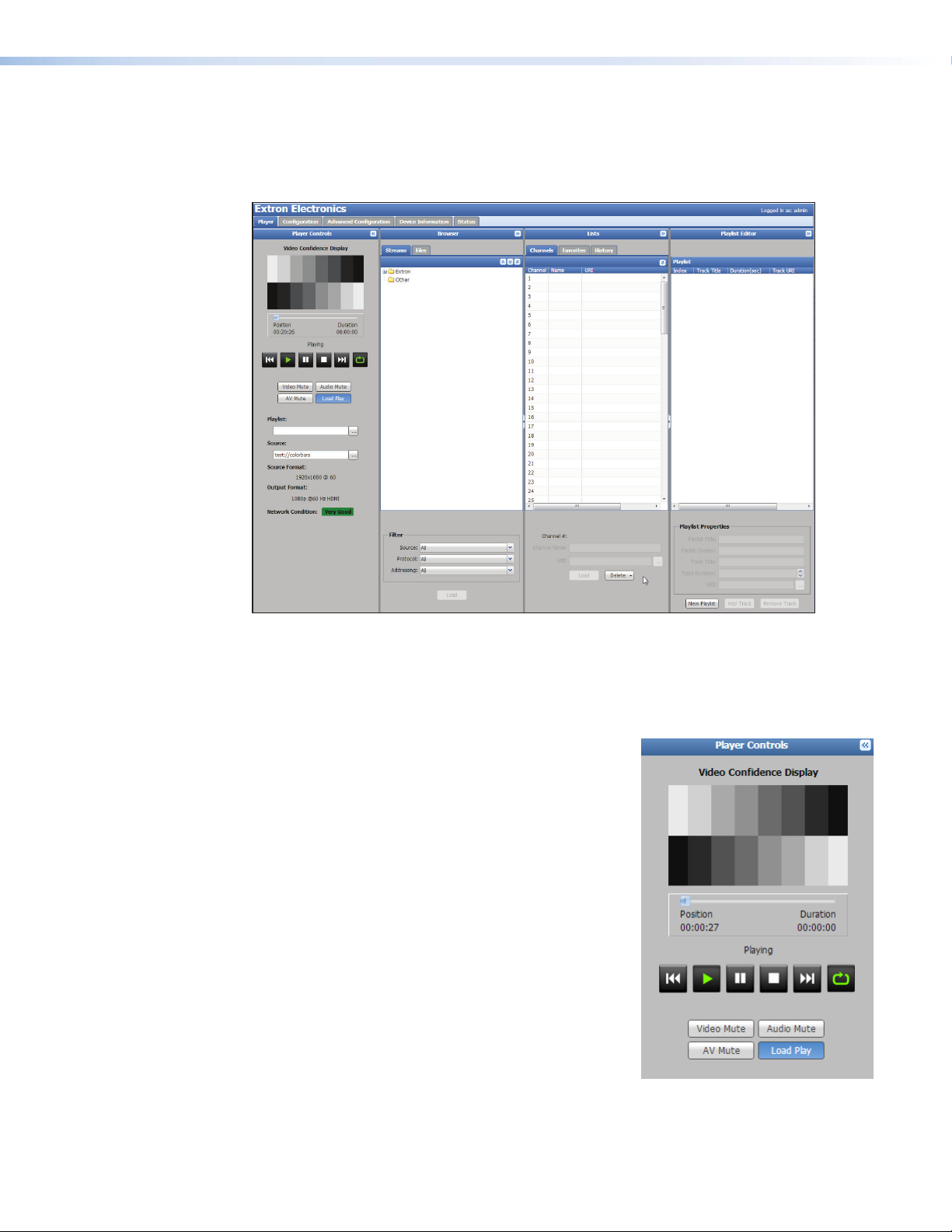
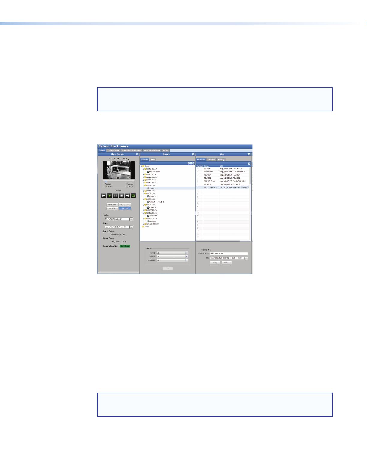
Player Page
Click the Player tab (see figure 13). This page has four panels; PlayerControls, Browser,
Lists, and Playlist Editor described in the following sections. Each panel expands or
collapses to provide additional screen space and can have second level tabs.
Figure 13. Player Controls Page
Player Controls
The Player Controls panel allows the user to select a source (clip, stream, or playlist),
monitor the playback video, and control playback.
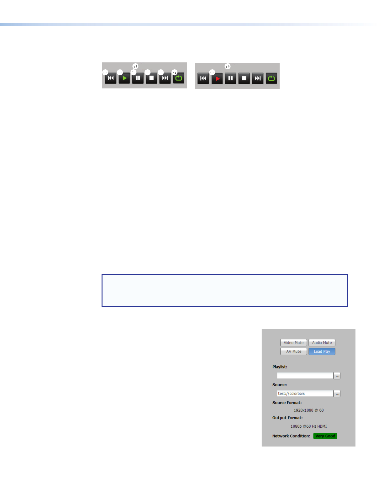
The Player page opens with the Player Controls
panel expanded. Changes made to the layout of the
player page are retained during the current session. For
instance, if a user switches to the Status page then
back to the Player page, the same view is maintained.
The Player Controls panel includes the following
features:
Video Confidence Display — The display shows a
series of monochrome snapshots corresponding to the
real-time output, updated every 2 seconds.
Progress Bar — Shows the position in time of the
currently playing clip. The current playback position is
on the left, and the total duration of the clip (if known)
on the right.
SMD101 • Web-based User Interface 16
Page 23
Status indicator and Player Controls — Text above the controls (figure 14, 1) indicates
the current decode state (stopped, paused, or playing).
Playing Stopped
2
2 33 44 55 66 77 88
Figure 14. Player Control Buttons
The controls are:
Return — If pressed within five seconds after the clip begins, returns to the previous clip
2
or stream and plays. If pressed after five seconds, returns to the beginning of the clip or
stream and plays.
11 11
Play — Begin normal playback.
3
Pause — Pause playback.
4
Stop — Stop playback.
5
Advance — Go to the next clip or stream and play.
6
Loop — Set the clip or stream to continuous play.
7
Error — The selected source cannot be played.
8
Mute controls
Allows the user to mute video only, audio only, or both. The indicator lights red when mute is
active. Pressing again unmutes the selection and the indicator goes out.
Load Play
Load play sets the response of the player when a source (stream, clip, or playlist) is loaded.
When enabled, the Load Play indicator is blue (shown enabled, below). As soon as a
source is loaded, the player immediately begins playback. When disabled (gray), the player
waits for user input before beginning playback of a loaded clip or stream.
Press Load Play to toggle the feature on or off.
NOTE: When a stream is loaded from the channel list (see Lists on page22) using
drag and drop in the player controls panel, or via remote access features such as
Ethernet, RS-232, wired IR, and the IR remote control handset, the stream or clip
plays immediately regardless of the Load Play configuration.
Playlist field
When a playlist is loaded, this field displays the path and
file name of the playlist. The full file and path name may be
abbreviated to fit the space available. The ellipsis button
(...) to the right of the text field opens a dialog to display
paths and file names too long for the field to display
completely or to edit the names. Playlist path and file
names can be copied to or from this field.
To load a playlist:
• Click and hold, then drag a playlist from the
browser window to this field.
• Right-click the playlist and select Load.
• Paste a playlist path and filename into this field from
the clipboard using <Ctl+C> and <Ctl+V>.
• Select a playlist file from the file tab of the file browser
panel (see Browser on page18).
When the playlist is selected, click Load at the bottom of the panel to bring it into the
playlist field.
SMD101 • Web-based User Interface 17
Page 24
Source field
When a source (clip or stream) loads, this field displays the path and file name. Click (...)
to the right of the text field to open a dialog displaying paths and file names too long for the
field.
A source can be loaded by any of these methods:
• Click and hold, then drag a source from the browser to this field.
• Use <Ctl+C> to copy, then <Ctl+V> to paste a URI or URL directly into the field. If
required, edit the name, then press <Enter> or click outside the field to confirm and load
the source.
• Select a source in the Browser>Files panel and click Load in the bottom panel.
• <Right-click> a source in the Browser>Files panel, and select Load.
Source format
Displays the format (DVI or HDMI), resolution, frame rate, and audio codec of the current clip
or stream.
Output format
Displays the current format (video resolution, frame rate, and audio format) of the output.
Network Condition
Displays a simple indication of current network conditions relative to the selected stream
(corresponds to the front panel network indicator). The network conditions are defined as:
• Very Good (green) — Network conditions allow full image and sound quality.
• Reduced (amber) — Network conditions such as packet loss, jitter, or delay are likely to
cause intermittent and noticeable degradation of image or sound quality.
• Poor (red) — Network conditions are likely to cause frequent and sustained degradation
or loss of audio and video.
• Very Bad (black) — Communication with the source is lost. The server could be
disconnected from the network.
NOTE: In many cases, the error correction features of the SMD101 allow good
image quality even when degraded network conditions are indicated.
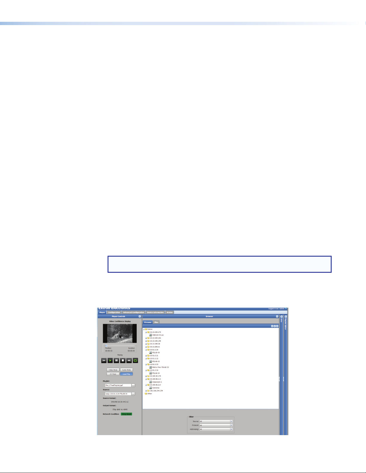
Browser
By default, the player page opens with the streams tab selected (see figure 15). Collapse it
to make more room for the lists or playlist editor panels. Tabs divide available source content
into Files and Streams.
Figure 15. Browser Panel, Streams Tab
SMD101 • Web-based User Interface 18
Page 25
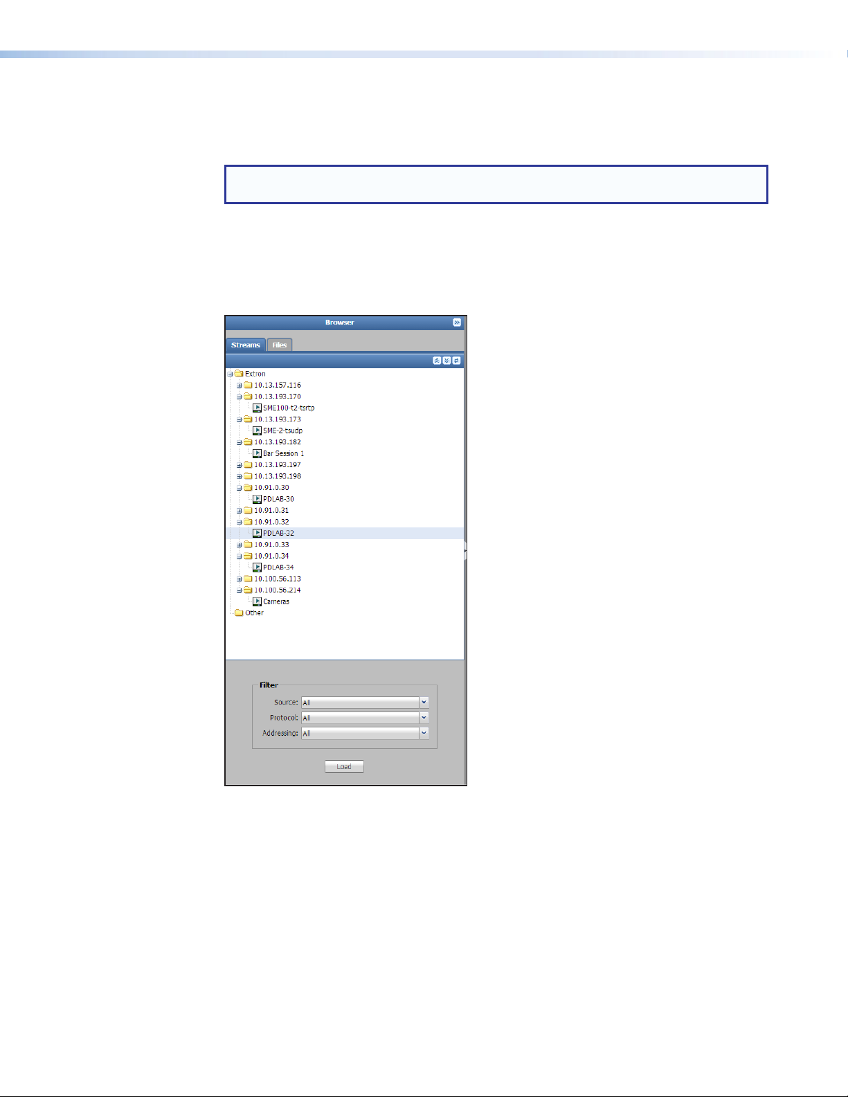
Browser Panel - Streams
The Streams tab in the Browser panel displays a list of streams identified on the local
subnet the SMD101 is connected to.
NOTE: The compatibility of streams listed in the browser is not assured. Stream
compatibility is verified by the SMD101 only as it is loaded for play.
The streams list is generated using information from Session Announcement Protocol (SAP)
messages broadcast on the local subnet.
Streams are grouped into folders according to information within the SAP message.
Standard panel controls expand, collapse, or refresh the list. In addition, click the
corresponding folder icon to expand or collapse individual folders.
Figure 16. Browser Panel, Streams
The default view showing the top folders expanded and sub-folders collapsed is restored
each time the web page opens. The folders are sorted by IP address.
To load a stream:
• Click and hold the desired stream, then drag it to the PlayerControls panel.
• Click the stream to highlight it, then click Load (below the Filter panel).
• Right-click on the stream, then select Load from the right-click menu.
SMD101 • Web-based User Interface 19
Page 26
Filter
Filters are provided to refine the list of streams viewed in the browser. There are three filters
with sub-filters to narrow the list of streams. The default choice for each filter is All.
• Source — Limits the browser to streams identified by their source device or location.
The drop-down list is populated with SAP source identification data. Limiting choices
are Extron or Other.
NOTE: A stream listed under Extron is defined as a member of the Extron group by
the SAP/SDP message. If the SAP/SDP message does not indicate Extron group
membership, it is listed in Other.
• Protocol — Limits the browser to streams identified by their transport protocol (UDP or
RTP). The list is dynamic, populated from SAP transport protocol data as the streams
are identified.
• Addressing — Limits the browser list to streams identified as unicast or as multicast.
NOTE: Unicast streams can only be played if the connection (destination)
address is set correctly at the decoder.
Load
Loads the selected stream for playing.
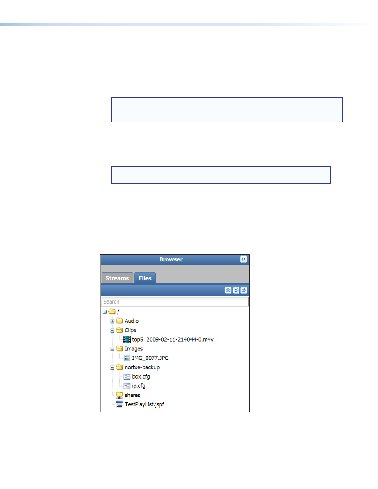
Browser Panel - Files
The Files tab opens a list of available clips and playlists in the file system including internal
storage (up to 175 MB for user content) and shared network folders (when mounted). Each
file type (audio, image, video, system, and playlist) has a different icon to distinguish it.
Figure 17. Browser Panel, Files
Separate controls fully expand, fully collapse, or refresh the list. In addition, click the
corresponding individual folder icons to expand or collapse.
SMD101 • Web-based User Interface 20
Page 27
In a current session, the folder view is retained after the user collapses the browser, changes
tabs within the browser, or changes the page (for example, from Player to Configuration).
The default view (top folders expanded and all sub-folders collapsed) is restored each time
the web interface is opened or refreshed.
NOTE: Right-click on file browser items for additional actions. When renaming files or
folders, the web interface enforces SIS file name and path requirements. Spaces are
not allowed.
When creating folders or uploading files using a SFTP client, spaces are allowed and
fully supported.
A clip or playlist is loaded for playback by dragging the selected item from the browser and
dropping it inside the Player Controls panel.
Filter
The drop-down filter limits the browser files display to any combination of the following file
types:
• Clips — compatible video files.
• Playlists — compatible playlist files created by the user.
• Images — compatible image files.
• Audio Only — compatible audio files.
NOTE: The quantity, size, and contents of shared folders on the network are initially
unknown. In order to maximize performance, the filter is applied only to one level
below the currently expanded folders.
When a user expands a folder, it is then indexed and filtered.
Load
Loads the currently selected file (audio, clip, image, or playlist) to the player.
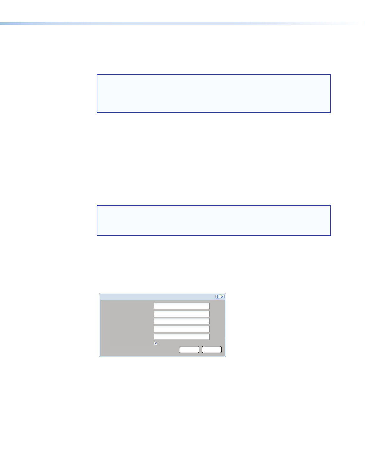
Network Shares
Click Network Shares to open the network shares dialog. This allows connection to a
network directory or drive for access to compatible files (see figure 18).
Network - Shares
Network Path:
User Name:
Password:
Options:
Local Name:
Reconnect at power up:
\\10.100.251.200\vm-smd\media
MediaShare
Save Cancel
Figure 18. Network Shares Dialog
See Play Video on Demand on page51 for information on adding and using network
shares.
SMD101 • Web-based User Interface 21
Page 28
Lists
The Lists panel features an editable channel list for use with the optional IR remote control
(see IR Remote Control on page56), a drag and drop favorites list for convenient
access of frequently played files, and the playback history. By default the player page opens
with the Lists panel expanded to the right of the browser.
NOTE: M3U, M3U8, and PLS playlist formats do not support Playlist Title or Playlist
Creator metadata. Text entered in those fields is not retained. If that information is
required for your application, use .jspf or .xspf playlist format.
The Lists panel has three tabs: Channels, Favorites and History (see figure 19).
Lists Panel – Channels tab
Figure 19. Lists Panel, Channels Tab
The Channels tab displays a list of current populated channels. Up to 99 channels are
individually defined by associating a stream, a file, or a playlist with a channel number and
(optionally) defining a logical name for the channel.
Fields below the channel list show the currently selected channel number, channel name,
and channel Universal Resource Identifier (URI). To assign a stream, file, or playlist to a
channel, select and drag an item from the browser Files or Streams panel to the desired
channel number. The channel name and URI are edited directly or new information is pasted
from the clipboard of the host computer. The ellipses to the right opens a dialog box to read
or modify longer paths or filenames.
To play a channel, select and drag an item from the Channels panel to the Player
Controls panel or select a channel and click Load. To mirror typical IR remote control
operation, the channel begins playing immediately regardless of the Load Play setting (see
Load Play on page17).
NOTE: Standard Windows keyboard shortcuts can be used to copy <CTL+C> and
paste <CTL+V> the stream, file, or playlist to a channel number, or to copy a channel
to the player.
The optional handheld IR remote control accesses this channel list to provide wireless
program selection (see IR Remote Control on page56).
SMD101 • Web-based User Interface 22
Page 29
To clear an item, select the item, then click Delete>Delete Selected. To clear all items,
click Delete>Delete All.
NOTE: Channel, Favorite and History lists are imported or exported using the
Configuration panel found on the Firmware Loader page of the Advanced
Configuration page.
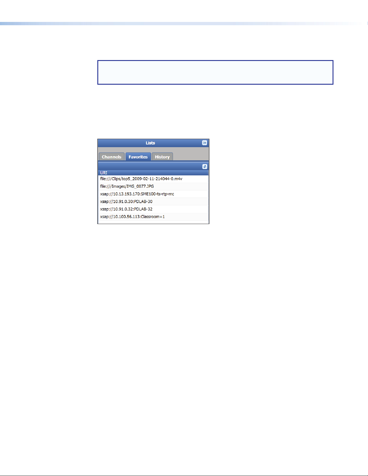
Lists Panel – Favorites
The Favorites tab displays a list of user defined favorite clips (see figure 20). Favorites are
clips, streams, or playlists more frequently played by the user. The favorites list is defined
by dragging a file or stream to the tab. The file location does not change. The favorites list
provides quick and easy access to more commonly used files and clips.
Figure 20. Lists Panel, Favorites Tab
Fields are available below the channel list to show the currently selected folder, favorites
name, and favorites URI. The folder name, favorites name, and URI can be edited or new
information pasted from the clipboard of the host machine. The ellipses (...) to the right
of the editable fields open a dialog box to allow longer paths or filenames to be read or
modified.
To load a favorite:
• Drag the selected item from the Favorites panel to inside the Player Controls
panel,
• Select an item and press Load.
To delete a favorite, select the favorite, then press Delete to clear.
SMD101 • Web-based User Interface 23
Page 30
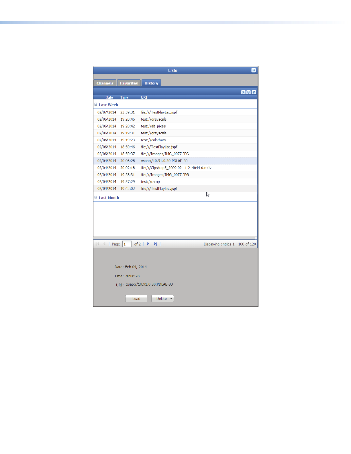
Lists Panel – History
The History tab displays a list of previously played clips, playlists, or streams with details of
the data and time the item played and the URI of the item, grouped by time period.
Figure 21. Lists Panel, History Tab
Fields below the history list show the date and time of the selected item along with the URI.
The URI can be copied or edited to create a new URI, which can be loaded and played (the
original entry remains unchanged).
A history item can be played by selecting and dragging the history item from the History
tab to the Player Controls panel, or select an item and click Load.
To clear history information, select the item or range of items, and click
Delete>DeleteSelected. To clear the entire history, click Delete>DeleteAll.
The files are not deleted, only the history entry.
SMD101 • Web-based User Interface 24
Page 31

Playlist Editor
34
By default, the Player page opens with the Playlist Editor open (see figure 22).
11223
Figure 22. Player Page, Playlist Editor
Playlists are stored in local media and are found using the files tab of the browser. Select a
playlist on the Files tab of the Browser panel (see figure 22, 2). The playlist opens in the
Playlist Editor panel for viewing or editing. The name of the currently selected playlist is
on the title bar at the top of the PlaylistEditor panel (4).
The sequence of the clips in the playlist determines the sequence the clips are played. Clips
can be reordered within the playlist using drag and drop.
4
NOTE: Multiple clips can be selected using the standard <shift> or <control> key
combination shortcuts.
To create a new playlist, select the target folder in the stream browser panel and press
NewPlaylist on the Playlist panel.
The playlist path can be changed at any time, but it is more convenient to make a folder
selection first. The playlist name (filename) is required. Title and author are optional.
Playlist Properties
The Playlist Properties panel can create a new playlist, add a new clip, stream,
or image (AddTrack), remove a track (Remove Track), or shorten the playing time of a
selected track in the playlist.
To create a new playlist:
1. Select Browser>Files.
2. In the Playlist Editor, click New Playlist to create an empty playlist. New playlists are
always created in the current folder of the Browser>Files panel by default, but can be
changed by the user as noted above.
3. To add files and clips to the playlist, drag and drop them from the browser to the playlist
editor or enter the filepath directly into the URI field of the Playlist Properties panel.
SMD101 • Web-based User Interface 25
Page 32

The playlist title, creator, track title, track duration, and URI of a currently selected clip in
the playlist are shown in the PlaylistProperties panel. If an attempt is made to add an
unsupported clip, an error message (“unsupported file format”) is presented.
NOTE: Playlist level metadata is not supported in M3U, M3U8, and PLS format
playlists.
le:///clips/hd_other.ts
Figure 23. Playlist - Clip Properties
Once files and clips are added to the playlist, the clip properties are in the playlist editor
and the Playlist Properties panel below the editor. The track title and duration can be
changed using either.
To change the track title:
• Double-click in the Track Title column of the selected track in the playlist editor and
enter the new title, or
• Double-click in the Track Title field of the Playlist Properties panel and enter the
new title.
To shorten the playing duration of a clip either:
• Double-click in the Duration column of the selected track in the playlist editor and
enter the desired duration time in seconds.
• Double-click in the Track Duration field of the Playlist Properties panel and enter
the desired clip length in seconds.
• Use the up and down arrows in the Track Duration field of the Playlist Properties
panel to scroll to the desired clip length in seconds.
SMD101 • Web-based User Interface 26
Page 33

The track duration, the length of time a clip plays during the playlist, can be shortened or
lengthened without changing the original clip. Although a duration can be set beyond the
clips original playing time, the transition to the next clip occurs when the clip completes.
NOTES:
• Clips in the playlist that are in network shares and local storage have known
durations. Streams in the playlist whether in local storage, network shares, or are
streamed live typically have an unknown duration.
• When playlists are assembled offline, it is possible to introduce incompatible,
damaged, or missing clips into a playlist without warning. The player always
attempts to play the entire playlist. Incompatible, damaged, or missing clips are
skipped.
When a playlist is edited, changes are saved immediately. If the playlist is active, the
changes are indicated by an asterisk following the playlist name until the playlist is reloaded.
Select a clip or clips and click Remove to remove individual or multiple clips from the current
playlist. When removing one or more clips, the user is presented a warning message
(“Press enter to remove the selected clips”) with an option to confirm or cancel
the operation. When multiple clips are removed it is not necessary for them to be part of a
contiguous range.
SMD101 • Web-based User Interface 27
Page 34

Configuration Page
The Configuration tab provides controls on the global navigation bar to adjust basic
features of the SMD101. The controls are in four groups; Video, Audio, On Screen
Display, and Automation accessed from a ribbon toolbar across the top of the screen
(see figure 24).
Video Configuration
Select Video to open the Video Configuration page (see figure24). The page allows test
pattern selection for troubleshooting or setup of connected displays, selecting the HDMI
output mode, and configuration of the stream buffering.
Figure 24. Configuration - Video Configuration Page
General Video Settings Panel
This panel allows selection of a test pattern. The confidence display shows a thumbnail of
the playing pattern (see figure 24).
Click the drop-down list under the test pattern confidence display and select a pattern from
the following:
• Alternating Pixels • Color bars
• Alternating lines • Grayscale
• Crosshatch • Ramp
• Crosshatch 4x4 • White field
Click the drop-down list again and select Off to stop playing the test pattern.
NOTE: When a test pattern is selected, source streaming stops and the test pattern
is switched to the output. If the output format is changed, the test pattern is also
stopped while the output reformats. You must then restart the test pattern from the
player controls (press Play) or select another test pattern.
SMD101 • Web-based User Interface 28
Page 35

HDMI Output panel
Select an output resolution and rate from a list of output timings. When the source (stream
or file) resolution or rate differs from the selected output, scaling and frame rate conversion
are applied. In addition, you can choose to match the output resolution to the timings of
the current stream or file (provided those timings are supported by the SMD101 and the
connected display) or to match the output with optimum timings for the display.
Output Timings — Click the drop-down list and select the desired format (see Output
Resolution and EDID Support Table on page4).
Match Stream/File — Automatically selects an output format based on the input
stream.
Match Display EDID — Selects an output format based on the best match of the input
stream format and available display formats provided by the EDID of the display.
Digital Format — Sets the digital output format from these selections:
• Auto (default)
• DVI RGB 444 (digital embedded audio is disabled)
• HDMI RGB 444
• HDMI YUV 444
• HDMI YUV 422
NOTE: HDMI video level range is set automatically according to defined standards
(0-255 for RGB and 16-235 for YUV (YPrPb).
Aspect Ratio — Sets the output aspect ratio.
• Fill — Scales the source to fill the display area. If the aspect ratios differ, the source
aspect ratio is not maintained.
• Follow (default) — Does not scale the source. If the aspect rations differ, the source
aspect ratio is maintained using black bars to fill areas where the source video does not
fit the display screen.
• Zoom — Maintains the source aspect ratio, but crops excess video to fit the screen.
Video Mute — Mutes only the active video.
Sync Mute — Mutes both video and sync allowing a connected display to go into power
save mode (if equipped).
NOTE: The current playback stops when changing the output timings, digital format,
or aspect ratio as the output adjusts. Press Play to restart the selected clip or test
pattern.
Buffer Settings panel
The stream buffer runs the stream into internal memory, delaying output video until the buffer
fills. This prevents normal network events from disrupting video output.
Buffer settings are configured to optimize the way stream data is handled for
specific applications. Where low latency (minimum delay) is required, reduce
the Bufferbeforeplayback(sec): time or disable buffering by unchecking
EnableBuffering. Where network performance is limited, increase the buffer times to
ensure sufficient data is available to prevent freeze or dropouts.
Enable Buffering — Place a checkmark in this box to turn buffering on. To turn buffering
off, click the checkbox again to clear the checkmark.
Buffer before playback (sec): — Sets the time in seconds the stream is buffered before
video output begins. Choose a time from 0.01 to 30 seconds. Default is 2.0 seconds.
Buffer before restart (sec): — Sets the time in seconds the video output is delayed after a
restart. Range is 0.01 to 30 seconds. Default is 6.0 seconds.
SMD101 • Web-based User Interface 29
Page 36

Audio Configuration
The Audio Configuration page (see figure 25) provides information and control of the
analog audio output. The controls do not affect embedded audio on the HDMI output.
Analog audio can be delayed or muted. A master gain control for the selected audio is
provided.
Figure 25. Configuration - Audio Controls
The analog audio output format is displayed in the Audio Output panel. Click Stereo to
maintain a 2 channel audio output. Select Dual Mono when there is only single channel
source audio. Dual mono provides two channel output from a single channel input or mixes
left and right channels and sends the mix to both the left and right outputs.
The audio delay control allows the user to achieve audio-to-video synchronization when
timing differences occur between the audio and video streams. By default, the audio and
video streams are synchronized (Audio Delay: = 0 mS). Audio delay is adjusted between
+255 to -255 milliseconds.
• Positive delay results in audio lagging video by the set value.
• Negative delay results in audio leading video by the set value.
NOTE: The source input must be restarted for an audio delay change to take effect.
Output audio can be toggled on and off using the master Mute button.
A master level control graduated in 1dB steps from -100 dB (full attenuation) to 0 dB (unity
gain) to set or match output levels. Move the slider or enter a value in the field below the
slider to adjust volume from 0 (maximum output) to -100 (no output).
Audio mute and level settings are retained through reboot or power cycle events.
SMD101 • Web-based User Interface 30
Page 37

On Screen Display
The On Screen Display (OSD) page (see figure 26) enables the display of realtime
information about the video output and device operation on a connected display (see
figure27).
On Screen Display
Status Information
Duration (Seconds): 5
Progress Bar
Enable OSD
Position: Left-Top
Save Cancel
Enable Progress Bar
Duration (Seconds):
5
Position: Center-Bottom
Save Cancel
Figure 26. Configuration Page - On-Screen Display
Status Information Panel
The Status Information panel controls the timing and position of the on-screen status
information that includes stream, network condition, and device information.
Extron Electronics
SMD 101 Stream Media Decoder
VIDEO STREAM 0
encoding: h264 video
width: 704
height: 576
framerate: 25
interlaced: false
STATUS INFORMAT ION
Network Condition: Very Good
Audio Bitrate: 124 Kbps
Video Bitrate: 3618 Kbps
SOURCE RATE
704x576 @ 25 AAC-LC
AUDIO STREAM 0
encoding: mpeg4_aac_audio
profile: Ic
channels: 2
rate: 44100
signed: true
DEVICE INFORMATION
CPU: 21%
Mem: 37% used
Temp: 58.5C
Date: 12/01/2013 15:10
192.168.254.254
FW: 1.20
OUTPUT RATE
1080p @ 60
Figure 27. On-screen Status Information Panel
Enable OSD — Click this checkbox to enable the status information.
Duration (Seconds) — Set the time in seconds the status information is on screen after
the start of playback using the adjustment arrows or enter the time (in seconds) directly.
Default is 5 seconds, maximum is 500 seconds. 501 seconds = always on. The IR remote
can toggle it on or off.
Position — Select the screen position from one of nine positions (left-top (default),
center-top, right-top, left-center, center-center, right-center, left-bottom, center-bottom,
right-bottom) using the drop-down list.
SMD101 • Web-based User Interface 31
Page 38

Progress Bar Panel
The progress bar is similar to the information shown underneath the live confidence display
in the PlayerControl panel. The bar shows the clip or filename and current playback
location. The current playback position is at the left of the progress bar. The total clip length
is on the right when a clip is selected and its length is known. If the playback is a network
stream, the total length is not likely known and the total time is blank. If the current selection
is part of playlist, or channel list, the channel number and name (if any) is at the upper right
corner (Ch 2 in figure 28).
The progress bar tracks the current playback position across the bar. Blue indicates the file
and gray indicates buffer fill.
Enable Progress Bar — Click this checkbox to enable or disable the progress bar.
Duration — Use the adjustment arrows or enter the time directly in the duration field to set
the time (in seconds) the progress bar is displayed. Default is 5 seconds, maximum is 500
seconds. 501 indicates the progress bar is always on. The IR remote can toggle it on or off.
Position — Using the drop-down list, select the screen position of the OSD from one of
nine positions: left-top(default), center-top, right-top, left-center, center-center, right-center,
left-bottom, center-bottom, and right-bottom.
Ch 1:SME100-Chan-1
Ch 2
Figure 28. Progress Bar OSD
Automation
The Automation page (see figure 29) provides features and configuration options that are
normally set once and continue automatically.
Figure 29. Configuration Page - Automation
SMD101 • Web-based User Interface 32
Page 39

Screen Saver panel
The screen saver activates when there is inactivity. Settings include:
Show Screen Saver: — The length of inactivity time (no stream decode, no commands
received, and no user input) before the screen saver starts. Click After to enable the screen
saver mode, then enter or select the number of seconds of inactivity before the screen saver
activates.
Color: — The color of the screen saver. There are three choices:
• Black presents a black screen.
• Blue with OSD bug displays a blue background with the message:
SMD101: No Source Input.
• Custom allows selection of a color using the drop-down pallet.
Mute Video and Sync — When the screen saver is active, sync is still sent to the
connected display. For the display to enter its own power save mode (if equipped), sync
must also stop. Check After and enter the number of seconds of inactivity before sync is
discontinued, up to 500.
Bootplay
Boot play is a feature that allows a source to be defined for automatic playback immediately
after power to the SMD101 is restored or cycled. The boot play source can be a clip, file, or
playlist. Select a source (a stream URL from the network, or a playlist or filename for locally
stored clips) to load on each power up cycle or reboot. Right-click the file and select Set
as Boot Play, or cut and paste the file into the boot play field. Alternately, type the folder
location or stream URL of the desired file directly into the entry field.
Failover
Defines the player response in the event stream data is interrupted. The time to wait after
the stream is lost, the solid background color that plays in the event of stream loss, and an
alternate source clip, image, playlist, or stream on the local drive can be selected.
Display Solid Color — The length of time after a stream loss before a solid color screen
is output to the connected display. Click the After checkbox to activate the failover mode.
Select the time after the stream loss is detected before the solid screen is output.
Color — The color of the failover output. There are three choices:
• Black presents a black screen.
• Blue with OSD bug displays a blue background with the message:
SMD101: No Source Input.
• Custom allows selection of a color from the drop-down list color pallet.
Source from Path Below: — Select a clip or image to display upon entering failover mode.
The clip or image must be on the local storage media. Right-click the file and select Set as
Failover Play or cut and paste the file into the field. Alternately, click Source from Path
Below: and type the folder location of the file into the entry field.
NOTE: Failover images or clips should always be located on local storage. This
provides a more reliable source in the event of network failure or the loss or relocation
of the original source.
SMD101 • Web-based User Interface 33
Page 40

Advanced Configuration Page
The Advanced Configuration page provides options that are not frequently changed.
The page is is always available, but options are dimmed depending on the current user
privileges. It provides initial setup and administrator level configuration.
Figure 30. Advanced Configuration Ribbon
Connection
The Connection Settings page allows configuration of parameters related to the LAN
(Ethernet) and serial ports.
Ethernet Settings Network Port Mapping
Use DHCP
(Obtain IP address automatically)
IP Address:
Subnet Mask:
Default Gateway:
DNS Server:
Host Name:
Link Local: 169.254.4.247
MAC Address: 00-05-A6-0A-12-73
10.13.193.168
255.255.0.0
10.13.0.100
10.1.0.7
SMD-101-0A-12-73
Reset to Default
Save Cancel
SFTP:
SIS (SSH):
Telnet (Extron SIS):
HTTP:
SNMP:
HTTPS/SSL:
Serial Pass-through:
Port Enable
22022
22023
23
80
161
443
Reset
Reset
Reset
Reset
Reset
Reset
Reset
Reset to Default
Serial RS-232 SettingsEthernet Diagnostics
Address to ping:
Ping
Mode:
Baud Rate:
Stop Bits:
Bits:
Parity:
SIS
9600
1
8
None
Reset to Default
CancelSave
Figure 31. Connection Settings Page
Ethernet Settings panel
This panel provides basic ethernet configuration including:
• Use DHCP — Click the checkbox to enable DHCP. The IP Address, Subnet Mask,
Default Gateway, and DNS Server fields dim.
• IP Address: — Under DHCP control, this field displays the assigned IPaddress.
Otherwise, enter a static IP address here.
• Subnet Mask: — Under DHCP control, this field displays the assigned SubnetMask.
Otherwise, enter a mask here.
• Default Gateway: — Under DHCP control, this field displays the assigned default
gateway address. Otherwise, enter the default gateway address here.
• DNS Server: — Under DHCP control, this field displays the assigned DNSServer
address.
• Host Name: — Enter a name for the device here. The name assists identification.
• Link Local: — An IP address automatically negotiated by the SMD101 when not
assigned a static IP address and DHCP is disabled, or when DHCP is enabled but a
DHCP server is not found.
SMD101 • Web-based User Interface 34
Page 41

• MAC Address: — The MAC address of the connected SMD101. The address is also
1
m
available on the rear panel label.
• Reset to Default: — Resets all network configuration to default.
• Save — Saves manual network configuration changes.
• Cancel — Discards manual network configuration changes.
NOTES:
• The DHCP assigned Gateway and DNS address are retained after DHCP is
deselected. They are reset using the reset button on the rear panel (see SMD101
Rear Panel Reset on page12) or using the web-based user interface (see
Reset Device on page42).
• The network interface restarts when changes are saved.
Ethernet Diagnostics panel
This panel provides a ping utility for troubleshooting network connection issues.
• Address to ping: — Enter an IP address (10.13.193.168) or a complete host name
(www.extron.com) in this field, then click Ping to start the utility. A dialog box with the
results of the ping opens.
www.extron.co
192.168.3.5
Figure 32. Network Ping Dialog
Network Port Mapping panel
This panel provides basic Ethernet configuration that includes:
• SFTP: — Set the port number for SFTP here. Check Enable to use the port.
• SIS (SSH): — SSH provides a method for a SSH client to establish a secure
connection to the player at port 22023, which then supports the SIS command set.
• Telnet (Extron SIS): — The port used by DataViewer or other telnet programs to
access the SMD101. Check Enable to use the port.
• HTTP: — Set the port number for HTTP here. Check Enable to use the port.
• SNMP: — Set the port number for SNMP here. Check Enable to use the port.
• HTTPS/SSL: — Set the port number for HTTPS here. Check Enable to use the port.
NOTE: Changing or disabling this port while using the default port (80) causes a
loss of the connection. Try https://<SMD101 IP> to reconnect to port 443.
• Serial Pass-through: — Set the port number for the serial pass-through feature
here. Check Enable to use the port.
• Reset to Default — Click to return all port mappings to default.
Default port numbers are shown in figure 31 on the previous page. Click the checkbox after
the port number field to enable the port entry in the associated port field. Click Reset to
return the port number to default.
SMD101 • Web-based User Interface 35
Page 42

Serial RS-232 Settings panel
This panel provides basic serial port configuration that includes:
• Mode: — Configures the port to receive SIS commands from an external host controller,
or to pass communication between the "serial pass-through" network port and the
serial port. Select the mode from the drop-down list:
• SIS — To set the serial port to the default configuration for SIS communication.
• Direct Access — To set the serial port to enable serial data passthrough.
• Disable — To prevent all serial port communications.
Click Save to enable the selection.
In addition, the serial port can be configured manually with the following drop-down
lists:
• Baud Rate: — Select the baud rate for the RS-232 port from this drop-down list.
• Stop Bits: — Select the stop bits for the RS-232 port from this drop-down list.
• Bits: — Select the data bits for the RS-232 port from this drop-down list.
• Parity: — Select the parity for the RS-232 port from this drop-down list.
• Reset to Default — Click Reset to Default to return the port mappings to their
defaults.
• Save/Cancel: — Click Save to save new RS-232 settings. Click Cancel to discard all
changes and return to the previous settings.
Firmware Loader
The Firmware Loader page provides a way to upload and install new firmware and to
export configuration settings from the connected SMD101, or import saved configuration
settings from another SMD101. Check for firmware updates on the product page at the
Extron website. Download the firmware to a location on the computer connected to the
SMD101.
Firmware
Current Firmware Version: 1.00
Select a firmware file to upload:
Browse
Upload Cancel
Configuration
Select a configuration file to upload:
Browse
Save Upload Cancel
Figure 33. Firmware Loader Page
NOTE: During a firmware upgrade, the file temporarily resides in the SMD101 local
user memory. There must be sufficient space available to accommodate the firmware
file for the update to succeed. For example, a 52 MB firmware upgrade file requires at
least 52 MB of unallocated memory. Prior to an update, check the available internal
memory (see Status Page on page45). If there is not at least enough to store the
entire firmware file, delete or remove files from the internal memory until there is.
SMD101 • Web-based User Interface 36
Page 43
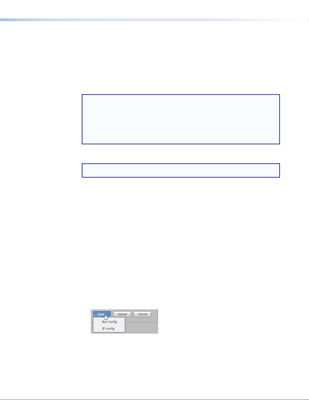
Firmware panel
• Current Firmware Version: — Displays the active firmware version. Compare the
version with the online version on the SMD101 product page at the Extron website, to
determine if you are running the most current firmware.
• Select a firmware file to upload: — This field displays the location of the update
firmware file. Click Browse, then locate and select the firmware file.
• Upload: — After the firmware file is selected, click Upload to begin the update. Cancel
stops the update and clears the Browse field.
NOTE: Depending on the browser, the firmware upgrade path displayed in the browse
folder field is not the same as the file path. The following list shows how the upgrade
path appears for the recommended browsers uploading a firmware file named
"49‑244‑50‑0.18.0001.eff‑full".
• Chrome: C:\fakepath\49‑244‑50‑0.18.0001‑full.eff
• Firefox: 49‑244‑50‑0.18.0000‑full.eff
• IE:
C:\upgrades\Peanut(SMD)\Build 0.18.0000\49‑244‑50‑0.18.0000‑full.eff
A dialog opens to indicate upload progress. When the upload completes, the device
firmware is updated. After the update, the SMD101 automatically reboots.
NOTE: Playback stops, and the connection is lost during the reboot, requiring a refresh
of the browser once the reboot is complete.
Configuration panel
A configuration file contains a snapshot (or record) of the relevant settings of the SMD101.
The settings are divided into two files: box.cfg with general settings, and ip.cfg with the
network configuration. These two files enable multiple SMD101 devices to be configured
identically (saving setup time), or to backup the current configuration of the SMD101.
Multiple config files can be saved, then restored in order to customize an SMD101 for
specific tasks.
To configure multiple devices with a single config file:
1. Configure the first SMD101.
2. Click Save to place the configuration file in a location accessible from each SMD101.
The drop-down list provides two options:
• Box Config — Select this option to save all settings including channel presets
but excluding network settings from both the Configuration and Advanced
Configuration pages.
• IP Config — Select this option to save all network related settings. The file
contains additional reference information such as the device name, date, and time,
but only the network settings are restored.
Figure 34. Save Config File
SMD101 • Web-based User Interface 37
Page 44

The files are saved to the host computer downloads folder and also saved to the SMD101
local memory nortxe-backup folder.
Figure 35. Configuration Files
NOTES:
• Using Firefox or Chrome, the config files are automatically named box.cfg and
ip.cfg and saved to both the SMD101 local memory (in the nortxe‑backup
folder( and to the host computer downloads folder (or designated location if
changed). From the host computer, they can be renamed or moved to a folder
selected by the user with a standard file browser.
• Using MS Internet Explorer, after saving the files to local memory, the browser
remains on a page with only the configuration text displayed. Press the back
button to return to the Player page.
• IE does not save the config files to the host computer. You must save the file using
cut and paste from the open web browser page, or extract the locally saved files
from the SMD101 local memory to the host computer (see Copying Config Files
Using Internet Explorer on page92).
To upload a configuration file to the same or another SMD101:
1. Select a configuration file to upload: — This field displays the location of the
configuration file for cloning a SMD101, or to reload a custom configuration for a
specific task. Click Browse to locate and select the file from the host computer or local
memory.
2. Upload: — Click Upload to begin the configuration change with the selected file.
Cancel stops the update and clears the Browse field.
After a configuration file (box.cfg or ip.cfg) is uploaded, the SMD101 automatically
restarts and applies the changes. The process takes about a minute.
SMD101 • Web-based User Interface 38
Page 45

Exec/Power Mode
The Executive and Power Mode page allows configuration of device control and power
settings.
Figure 36. Exec/Power Mode Page
Control Options Panel
• IR receiver: — The front panel IR receiver or rear panel IR receiver input can be
enabled or both can be disabled. Select from the following options:
• Disable all IR reception — When selected, ignores all IR commands.
• Enable the front panel IR receiver — When selected ignores IR commands
• Enable the rear panel IR receiver — When selected, ignores IR commands
• Disable Video Confidence Display — Click this box to disable the video confidence
display on the player controls panel. Click again to enable the display.
from the rear panel wired IR input.
from the front panel IR receiver.
The SMD101 features an energy conserving mode. Low power standby stops the stream
and places all processing in a low power condition awaiting external commands.
• Full Power: — Click to select normal operation (default).
• Low Power‑Standby State: — Click to immediately enter standby mode. Normal
operation can be resumed by clicking the full power button, by sending a power on/off
command from the IR remote (if enabled in control options), or when a SIS command
that sets a value is received on the network or serial ports (see Automation on
page32).
• Auto Standby Delay: — Enter a time in minutes or use the list buttons to scroll to the
desired time selection the device waits after the inactivity period is met before entering
standby mode. Default: off.
NOTE: When the SMD101 comes out of standby mode, the first clip can fail to
load or play automatically. Any "set" command causes the SMD101 to resume
full power state, but command execution could be delayed. For best results,
before sending any other commands, always send a 0psav SIS command
to bring the SMD101 out of standby (see Power Save and Standby on
page68).
Power Mode Panel
SMD101 • Web-based User Interface 39
Page 46
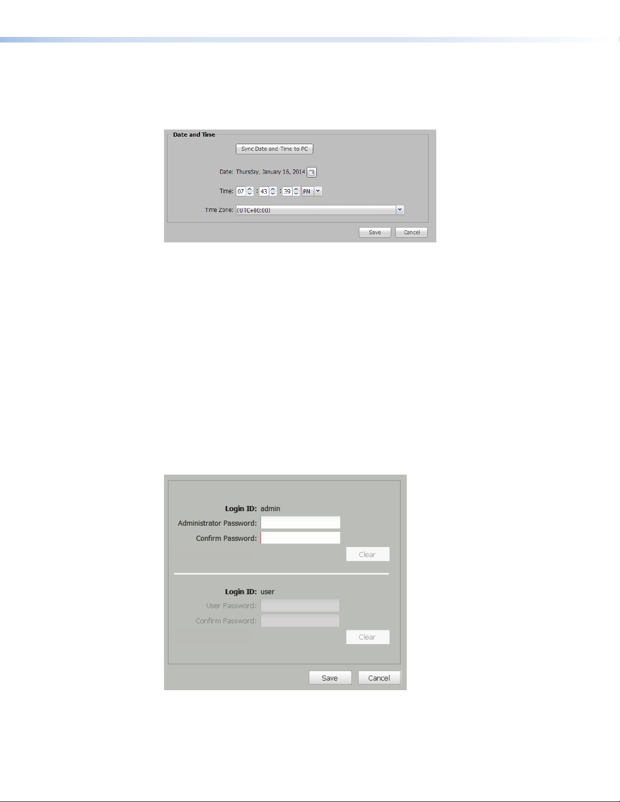
Date and Time
The Date and Time page allows automatic sync of the date and time from the connected
control device, or provides manual setting of the date and time, timezone, and daylight
saving mode.
Figure 37. Date and Time Panel
• Sync Date and Time to PC — Click this button to force the SMD101 date and time to
• Date — Press the Calendar icon on the right side of this field to manually select the
• Time — Use the scroll list buttons, or enter the time directly to set the current time.
• Time Zone — Use the drop-down list to select your time zone.
• Save/Cancel — Save the time and date or cancel the entries.
sync with the connected control PC.
current date from the calendar dialog box.
Password
The password page provides user and administrator (admin) ID passwords for security and
to limit access. No other login IDs are available. The admin password provides access to all
pages and all selections to anyone logging on with Login ID: admin. Prior to an admin
password being set, there is no security challenge to access the SMD101. Any user who
accesses the interface has full administrator privilege.
Figure 38. Password Page
An administrator password can be set without setting a user password. When only an
admin password is enabled, the user login is inactive. All users must login using the admin
ID and administrator password for access.
SMD101 • Web-based User Interface 40
Page 47

When an admin password and user password are both set, logging in with the user ID and
password limits access. Full player control is allowed, but configuration options are limited
including:
Player Page:
• Create a new playlist, but cannot modify or delete an existing playlist.
• Full player control
• Use play, stop, pause, loop, go to previous or following buttons
• Select items to play from input streams, files, channels, favorites, history lists,
playlists
Configuration Page:
• Video, Audio, and OSD panels — Full Access
• Automation — View Only Access (pages are dimmed)
Advance Configuration Page:
• View only access (all selections are dimmed)
Device Information Page:
• View only access (all selections are dimmed)
Status Page:
• View only access (all configurations are dimmed)
An attempt by a non-admin user to access a page or selection that requires administrator
security opens a dialog box stating the privileges violation.
An administrator password must enabled before a user ID and password can be set.
NOTE: Passwords must be less than 12 characters long, no spaces, and consist of
alpha-numeric characters only.
To set an administrator password:
1. Type a password in the Administrator Password: field.
2. Duplicate the password in the Confirm Password: field.
3. Click Save.
To clear the administrator password, you must be logged on the SMD101 with
administrator privileges.
1. In the Login ID: admin panel:, click Clear.
2. Click Save.
The user interfaces (DWP, SIS, SFTP) no longer require a password. The user is logged out
and automatically logged back in as the administrator.
NOTE: If a user password is active, clearing the administrator password also clears the
user password.
To change an admin password, you must be logged on the SMD101 with admin privileges.
In the Login ID: admin panel:
1. Click Clear to remove the previous password, or type a new password in the
Administrator Password: field.
2. Duplicate the password in the Confirm Password: field.
3. Click Save.
The new password is now current and the SMD101 automatically logs off. Login with the
new password to continue.
SMD101 • Web-based User Interface 41
Page 48

Reset Device
To set, change, or clear a user password you must be logged on as an admin.
1. Click Clear to clear a previous password, then type a password in the User Password:
field. If this is the first time a password is set, type the password in the User Password:
field.
2. Duplicate the password in the Confirm Password: field.
3. Click Save.
Provides several options to reset the SMD101 if hardware or software conditions require.
NOTE: Proceed with caution. Some reset modes intentionally delete all user files,
media content, and settings from internal memory.
Figure 39. Device Reset, Reset Options
• Reset Device settings to default — Resets all hardware and software to default
condition, but retains user files and IP settings for communication.
• Reset Device settings and delete internal user files (Retains all IP settings)—
Resets all hardware and software to default condition, deletes user files stored in
internal memory, and retains IP settings for communication.
• Reset Device settings, delete internal user files, and reset all IP settings —
Resets all hardware and software to default condition including IP settings.
NOTE: If the control PC is connected via the Ethernet port, communications is
broken. Use the default IP address (192.168.254.254), the front panel config port,
or the rear panel RS-232 port to reconnect.
To select a reset, click the button to the left of the desired option. The radio button lights.
Click Apply to begin the reset. See the SMD101 Reset Summary on page83 for a
comparison of the reset modes.
SMD101 • Web-based User Interface 42
Page 49

SNMP
The Simple Network Management Protocol (SNMP) page facilitates the exchange of basic
network management information to provide monitoring, control, and to collect error
information.
Figure 40. SNMP Page
SNMP panel
• Enable SNMP — SNMP is disabled by default. Check this box, then click Save to enable
SNMP. If SNMP is enabled, a strong password (community strings) is recommended.
• Unit Contact — The name of the person to contact with questions on operation or
configuration. To change the contact information, enter the new information in the field,
then click Save.
• Unit Location — The location of the device. For easier identification on the network,
enter a descriptive name in this field, then click Save.
Password Management panel
Access to the SNMP page can be public or private. Public access provides read-only
access to all SNMP features. Private access allows both read and write access.
The two passwords must be different to provide security from unwanted changes.
Click Public or Private to set or reset the associated access password. Enter the new
password, then enter it again in the Confirm Password field. Click Save to make the
password current.
SMD101 • Web-based User Interface 43
Page 50

Device Information Page
Displays both device (factory) and user defined information.
Figure 41. Device Information Page
Factory Defined Information panel
Displays read-only technical information about the SMD101 including:
• Model Number — The model number of the device.
• Model Description — The marketing description of the device.
• Part Number — The sales number of the device.
• Firmware Version — The current firmware version.
• Firmware Build — The specific build number of the firmware.
• MAC Address — The Media Access Control (MAC) address of the device.
• Default Web Version — This number indicates the revision of the SMD 101 embedded
• License Information — Click this button to open the License Information dialog.
web pages.
Figure 42. License Information Dialog
The dialog lists all third-party applications used by the SMD101 with links to the license
agreements. Click on the blue links to open the agreement page.
SMD101 • Web-based User Interface 44
Page 51

Status Page
User Defined Information Panel
Displays information input by the user including:
• Device Name — A unique name to identify the device on the network.
• Device Location — (optional) The location of the device.
NOTE: The device name and location must begin with an alpha character. Other
restrictions are detailed in the help file and tool tips.
The Status page displays current operating condition and statistics related to the
performance of the device. The page information updates every ten seconds.
Figure 43. Status Page
The Status page provides network statistics with information on the performance of the
SMD101. It includes statistics organized into three panels: Network Statistics, Device
Status, and Local Storage.
Network Statistics panel
The Network Statistics panel is divided into two subpanels: Current Stream and
Total.
Network Conditions — Monitors and displays information concerning network traffic
including:
• Network Condition: — Very Good, Good, Poor, or Disconnected.
• Link Speed: — The speed of the connection negotiated with the link partner (1Gbps,
100Mbps, 10Mbps).
The Current Stream panel displays information about the currently playing stream, clip, or
file including:
• Peak Stream Bitrate: — Populated for streams only. The combined audio and video
bit rate for the current stream.
• Audio Bitrate: — The current stream audio bitrate.
• Video Bitrate: — The current stream video bitrate.
• Received Packets: — Total received packet count for the current source since
playback of the stream started.
SMD101 • Web-based User Interface 45
Page 52

• Dropped Packets: — Total dropped packets for the current source since playback of
the stream started.
• Dropped %: — Total percentage of dropped packets for the current source since
playback of the stream started.
• Jitter: — For transport streams, audio and video streams are combined for this
value.
• Audio Jitter: — For elementary streams, the audio stream jitter in milliseconds.
• Video Jitter: — For elementary streams, the video stream jitter in milliseconds.
The data in all current stream catagories resets automatically when a new stream is selected
or when play stops.
The Total panel displays a running total of raw network statistics from the interface for all
streams, files, or clips played since the last manual reset including:
• Collisions: — Always zero for full duplex links.
• Rx_Bytes: — Receive data statistics.
• Rx_dropped: — Receive data statistics.
• Rx_errors: — Receive data statistics.
• Rx_packets: — Receive data statistics.
• Tx_Bytes: — Transmit data statistics.
• Tx_dropped: — Transmit data statistics.
• Tx_errors: — Transmit data statistics.
• Tx_packets: — Transmit data statistics.
Press Reset Totals to return the values in the Total panel to zero. The information
monitoring begins automatically after each reset.
Device Status panel
Device Status panel — Monitors general operating conditions including:
• Power Mode: — Operating or standby.
• Temperature: — Current internal temperature of the device. Readings above 60°C
could indicate excessive ambient termperature or insufficient ventilation and should be
investigated.
• Processor Usage: — A general indication of the device workload.
• Memory Usage: — Provides an indication of volatiile memory usage. It is typically 15%
after a power cycle, and expected to approach 100% after playing large clips from
shared network folders.
• Up Time (operating) Hours: — The time in days, hours, and minutes since the
SMD101 was powered up or reset.
Local Storage panel
The Local Storage panel provides about the user accessible non-volatile storage including:
• Type — Internal
• Name — User Content (can not be changed)
• Total — Total size of the internal non-volatile storage in megabytes.
• Used — Size of the files currently in local storage in megabytes.
• Available — Currently unallocated drive space.
NOTE: Used plus Available may not exactly add up to the Total size due to system
requirements.
SMD101 • Web-based User Interface 46
Page 53

Browser Idle
To conserve the host computer resources, after 60 minutes, the browser accessing the
SMD101 web interface stops requesting status and video confidence updates. An idle
dialog box opens (see below).
This feature does not idle or affect SMD101 operation. It suspends the automatic browser
updates for the video confidence display to conserve network and PC resources. Press
Resume to force the browser to reconnect to the SMD101 and begin normal updates.
SMD101 • Web-based User Interface 47
Page 54

Advanced Player Configuration
The SMD101 can play video on demand, video from a network share, and video from its
own local memory. The following section includes SMD101 configuration for playing those
videos and how to configure the SME100 for stream discovery that includes the following
topics:
Loading Content to Local Storage Using SFTP
Play Video on Demand
SME100 Stream Discovery
Connecting to Streams Without SAP Announcements
NOTE: In large systems, streams are easier to locate if the encoders are configured for
SAP announcements.
Loading Content to Local Storage Using SFTP
The SMD101 has internal memory reserved for local content. Local content is viewed from
the browser Files tab. A typical folder structure for the internal memory is shown below.
Browser
Files
/
audio
Audio-File-1.m4a
clips
Video-clip-1.mp4
images
1920x1080-Image.jpg
nortxe-backup
shares
MediaShare
NOTES:
• TMP folders are not accessible.
• The nortxe-backup folder only exists after configuration files are saved.
Content (up to 175MB total) can be transferred directly to the SMD101 from a computer on
the same network using an FTP client such as Filezilla, a free FTP program available here:
https://filezilla-project.org/download.php?type=client
SMD101 • Advanced Player Configuration 48
Page 55

Download and install the FileZilla program.
After installation, run the program.
1. From the toolbar select File>Site Manager.
The SiteManager dialog opens.
General
Host:
Protocol:
Logon Type:
User:
Password:
Account:
Comments:
Advanced Tr ansfer Settings Charset
192.168.193.165 22022
SFTP-SSH File Transfer Protocol
Normal
admin
*****
Port:
Figure 44. SFTP Site Manager Dialog
2. Enter the SMD101 IP address in the Host: field.
3. Enter 22022 in the Port: field.
4. Select SFTP in the Protocol: drop-down list.
5. Select Normal from the Logon Type: drop-down list.
6. Enter admin in the User: field.
7. Enter the SMD101 admin password if one is set. Otherwise leave the Password: field
blank.
8. Click Connect to start the connection routine.
Filezilla establishes a connection to the SMD101 at the IP address in the Host: address
and logs in.
SMD101 • Web-based User Interface 49
Page 56

Filezilla defaults to the root of the SMD101 local memory (on the right in figure 45) and
shows all files and folders currently in memory. Users can create folders only in the top level
(root) of the SMD101 file system.
In figure 45, a file is uploaded from the PC to the SMD101 Clips folder.
Local site:
C:\Users\Videos\MediaShare
Remote site:
PC file uploads to:
PC Folders and Files SMD 101 Folders and Files
Figure 45. Filezilla Folder Browser
NOTES:
• The media folder is reserved for system use. DO NOT upload user content files
(clips, audio, or images) to this folder.
• Using SFTP to transfer files to the SMD 101, if the file size exceeds the available
space, the file is truncated and is not playable. When working near the capacity
limit of the SMD 101, pay close attention to the SFTP client messages for transfer
errors.
Right-click on a file for quick access to file and folder functions. See the Filezilla help files for
additional information.
Figure 46. Filezilla Right-click Menu
SMD101 • Web-based User Interface 50
Page 57

Play Video on Demand
Network Path:
Options:
Local Name:
\\192.168.127.101\SharedFolder
Network - Shares
MediaShare
Save Cancel
Network Shares
User Name:
Password:
Reconnect at power up:
Network - Shares
Network Path:
Options:
Local Name:
\\10.100.251.200\vm-smd\media
MediaShare
Save Cancel
Password:
User Name:
Reconnect at power up:
The SMD101 can play video on demand from network shares and local storage supporting
the following file types:
Video: mp4, ts, m2t, m2ts, mov*, 264, m4v, flv*, and sdp.
NOTE: *Supports files that use H.264 encoding and AAC audio only.
Images: bmp, jpg, jpeg, tif, tiff, png, and gif.
NOTE: TIFF files using JPEG compression are not supported.
Audio: wav, aac, and m4a.
Playlists: jspf, m3u, m3u8, pls, and xspf.
Play Video from a Network Share
The shared folder must be added to the player browser file list.
To add a shared file folder:
1. From the files browser, click Network Shares. The Network Shares dialog box opens.
Figure 47. Network Share Configuration
2. Enter the path of the shared folder.
Network Path: Server address (or server name) and share name format depending on
protocol:
SMB/CIFS: \\<server_ip_address>\<share_name>\<optional_
directory>
NFS: server:/<share name> where server can be the IP address or host name
of the server.
NOTE: Network shares supports both IP address and host name path options. For
example, the host name in figure 47 is HOSTSERVER. The Network Path: name is
then: \\HOSTSERVER\SharedFolder.
4. If the folder has a user name and password assigned, enter them in the next fields.
User Name: Optional user name, if required.
Password: Optional password for the user name.
5. If necessary, enter additional switches into the options field (see Network Shares
Dialog on page85). This field is used to pass credentials, if required. By
default, the CIFS mount adds “user=” and “guest=” to the mount options, for an
anonymous login. No spaces are allowed between the user and password (Example:
user=username,pass=password).
SMD101 • Web-based User Interface 51
Page 58

6. Enter a name for the shared file to ease identification in the browser.
NOTE: The local name for the shared folder (in this example, MediaShare) is
optional. If the user does not define a name, it defaults to the server folder name.
7. Click Reconnect at power up: if you want the connection to persist.
8. Click Save.
The SMD101 connects to the shared folder and places it under the default Shares
folder of the files browser (see figure 48).
images
MediaShare
Figure 48. Browser Shares Folder
To play a file shared on the network share, from the browser files tab, drag and drop the
selected file in the Shares folder in the player panel (see Player Controls on page16).
NOTE: Reliable playback of content from network shares depends on server and
network performance. If playback issues are apparent, verify that the server and
network performance are sufficient for the content bitrate, or try a lower bitrate clip.
SMD101 • Web-based User Interface 52
Page 59

SME100 Stream Discovery
Multi TS/RTP 238.13.197.190 60000 1500
Stream Control Stream Method Destination IP Destination Port MTU
SAP Control Session Name Session Description Keywords Author Announce Frequency
QoS (Differentiated Services)TTL
sec
Streaming Configuration
Enable
Enable
Test Pattern 1 Bars and Tones test, pattern Extron1
Normal (CS3)10
5
For SME100 stream discovery in the SMD101 stream browser window (see Browser
Panel - Streams on page19), the SME100 must have both Stream Control and
SAP Control enabled. Figure 49 shows the SME100 settings. From the SME100 default
web page (see the SME100 User Guide), select the Encoder Configuration link, then
Encoder Settings to open the configuration dialog shown in figure 49 below.
Figure 49. SME100 Encoder Configuration Panel (Partial View)
In both the Stream Control and SAP Control drop-down lists, select Enable. Choose a
Destination IP and DestinationPort which avoid conflict with other multicast devices
on your network, then enter them into the appropriate fields.
With SAP Control enabled, the SME100 session name (Test Pattern 1) is listed in the
SMD101 stream browser page in the Extron folder. To connect the stream, from the
browser, drag and drop the stream anywhere on the Player Controls panel (see Player
Controls on page16).
If an SME100 is configured for RTSP multicast, the SMD101 must still connect to it using
the SME100 IPaddress (for example rtsp://192.168.254.100/extron) rather than
the typical multicast IP address (for example rtsp://239.10.193.165).
If the SME100 is set up for push streaming (Stream Control Enable), the RTSP bitrate is
limited to 5Mbps on startup or restart. Although it can be higher, it is not recommended.
If higher bitrates are required, only a single stream method should be active.
Push Streaming (Unicast Port Numbers)
RTSP Multicast (Pull Streaming)
In systems with more than one SME 100 encoder using any of the unicast push methods
(TS/UDP, TS/RTP, ES/RTP) to a single SMD101 decoder, each SME 100 must use a unique
port number (such as 60000 and 61000)
Multicast
For systems where streams from one or more SME100s are received and decoded by
multiple SMD101s, multicast addressing is strongly recommended. All network switches
must be suitably rated and correctly configured for IGMP snooping and multicast filtering
with an active IGMP querier (possibly the network switch) available on the local subnet for
optimum performance.
SMD101 • Advanced Player Configuration 53
Page 60

Connecting to Streams Without SAP Announcements
For a source that is not configured for SAP announcements (such as IP cameras), the RTSP
(pull) stream URI is entered directly in the Source field of the SMD101 player controls. The
URI prefix (udp in the example below) corresponds to the streaming method.
UDP or RTP Connections
To connect the SMD101 to a stream using the destination port of the encoder, use the
following template:
udp://@:<destination port>
For example, to connect to a SME100 stream, enter the following URI in the SMD101
Source field (see Source field on page18):
udp://@:60000
The SMD101 also supports the URI formats:
rtp://192.168.254.254@192.168.254.254:60000
and
rtp://@192.168.254.254:60000
HTTP Connection to an SME100
To connect SME100 unicast or multicast push streams over HTTP, use the following
templates.
For unicast streams with no password, the URI format is:
http://<sme100_ip>/web/output1.sdp.
For multicast RTP over UDP RTSP (pull) streams with no credentials set, the URI format is:
http://<sme100_ip>/web/multicast.sdp.
NOTE: A typical IPv4 address for an SME100 device on a private network is
192.168.nnn.nnn or 10.nnn.nnn.nnn). A multicast address is in the range
224.nnn.nnn.nnn to 239.nnn.nnn.nnn.
If the encoder has an active admin password, it challenges the connection. An admin or
user password is required for connection. To play the stream, the user name and password
must be embedded in the URI entered in the Source field.
For unicast or multicast PUSH streams with a password, the URI format is:
http://user:password@<sme100_ip_adr>/web/output1.sdp.
For multicast RTP over UDP RTSP (pull) streams with a password, the URI format is:
http://user:password@<sme100_ip_adr>/web/output1/multicast.sdp.
In the following example, connect to a unicast RTSP over UDP stream broadcast from the
SME100 in figure 49 on page 53, using an admin password “123456”.
1. Locate the HTTP stream in the streams browser (see Player Page on page16).
2. Drag and drop the stream into the player panel. An error message indicates the stream
load failed. The URI of the stream is shown in the Source: field.
3. Click the ellipsis (...) to open the full file path.
http:192.168.254.254/web/extron.sdp
SMD101 • Advanced Player Configuration 54
Page 61

4. Add the SME100 user name and password.
http:192.168.254.254/web/extron.sdp
http://admin:123456@192.168.254.254/web/extron.sdp
5. Press <Enter> to load the stream.
The stream loads. If Load Play is active, the stream begins playing. If Load Play is not active,
press play (see Player Controls on page16) to play the stream.
Use the templates below to connect the SMD101 player to SME100 encoder streams.
Substitute the SME100 IP address for <SME100_IP>.
PULL Streaming: URL
RTSP Unicast
RTSP Multicast
RTSP://<SME100_IP>/extron
RTSP://<SME100_IP>/extron
or
HTTP://<SME100_IP>/web/multicast.sdp
Table 1. Pull Stream URLs
PUSH Streaming:
Unicast
TS/UDP
TS/RTP
ES/RTP
UDP://@:<DESTINATION_PORT>
RTP://@:<DESTINATION_PORT>
HTTP://<SME100_IP>/web/output1.sdp
Multicast (<DESTINATION IP> address must be the multicast IP address)
TS/UDP
TS/RTP
ES/RTP
UDP://@<DESTINATION_IP>:<DESTINATION_PORT>
RTP://@<DESTINATION_IP>:<DESTINATION_PORT>
HTTP://<SME100_IP>/web/output1.sdp
Table 2. Push Stream URLs
NOTES:
• <SME100_IP> is the IP address of the SME100 encoder.
• UDP and RTP DESTINATION_PORT default is 60000.
• For ES/RTP, SAP is available in "Video only" stream mode.
SMD101 • Advanced Player Configuration 55
Page 62

IR Remote Control
The optional handheld IR remote control provides selection of pre-defined streams and
files, and direct control over playback. Features include standard transport controls for play,
pause, and stop. Up to 99 pre-configured channels can be directly accessed using the digit
buttons.
The following list details the available functions.
POWER — Toggles the SMD101 power on and off.
CHANNEL — Steps up or down through the channel list from
the last selected channel.
VOLUME — Increase and decrease output volume to a display
device connected to the SMD101 (see Rear Panel Features
on page9).
Digits — Provides direct selection of up to 99 pre-defined
channels (see Lists Panel – Channels tab on page22).
AV MUTE — Mutes both the outgoing audio and video but
allows a stream to continue playback.
INFO — Launches an onscreen display with details of
the currently active stream (see On Screen Display on
page31).
ENTER — After channel entry using direct selection (see
Digits, above) the entry is accepted after a short delay.
Press Enter after the channel entry to change to the channel
immediately.
VIDEO MUTE — Mutes and unmutes only the video output.
AUDIO MUTE — Mutes and unmutes only the audio output.
PROGRESS — Provides real-time information of the current
playback stream in the on-screen display of a connected
display. It includes the total play time of the stream and the
current position of playback. The on-screen display duplicates
the player controls (see Progress Bar Panel on page32).
TRANSPORT CONTROL — Provides remote access of the
player controls panel (see Player Controls on page16)
including:
• PLAY — Begins normal playback of the selected stream or
file.
• PREV — When a playlist is loaded, returns to the previous track.
• PAUSE — Pauses the current playback freezing the last decoded frame.
• NEXT — When a playlist is loaded, moves to the next track.
• LOOP — Places the currently selected clip or playlist into an endless loop.
• STOP — Stops the playback of the current source.
SMD101 • IR Remote Control 56
Page 63

Remote Communication and Control
This section describes SIS programming and control of the SMD101, including:
• Connection Options
• LAN (Ethernet) Port
• Host-to-device Communications
• Command and Response Tables
Connection Options
The SMD101 Streaming Media Decoder can be remotely connected via a host computer or
other device (such as a control system) attached to the rear panel RS-232 port or LAN port,
or the front panel USB Config port.
The SMD101 can be configured and controlled using SIS commands or embedded web
pages. SIS commands can be executed using the Extron DataViewer program, found on
the Extron website.
RS-232 Port
RS-232 protocol:
• 9600 baud • no parity • 1 stop bit
• 8 data bits • no flow control
See RS-232 Port below, for additional details on connecting the RS-232 port.
USB port details:
The Extron USB driver must be installed before use (see Front Panel Configuration Port
on page58).
LAN port defaults:
SMD101 IP address: 192.168.254.254
Gateway IP address: 0.0.0.0
Subnet mask: 255.255.0.0
DHCP: off
The SMD101 has a serial port that can be connected to a host device such as a computer
running a HyperTerminal utility, or the Extron DataViewer utility. The port makes serial control
of the player possible. Use the protocol information listed above to make the connection
(see Host-to-device Communications on page61).
The port can also be configured as pass-through for direct RS-232 control of a connected
display using serial commands via the network.
SMD101 • Remote Communication and Control 57
Page 64

Front Panel Configuration Port
The mini type B USB port is located on the front panel (see Front Panel Features on
page8). It connects to a host computer for configuration using SIScommands with
DataViewer.
To connect the SMD101 to a host computer:
NOTE: If an Extron USB device has never been connected to the host computer,
prior to connecting the SMD101 config (USB) port for the first time, you must install
and activate the USB driver. The simplest way to do this is to install DataViewer (see
DataViewer on page93) or obtain the driver from the SMD101 product page at
www.extron.com.
1. After the USB driver is loaded, connect a USB A to mini B cable between the Config
port on the SMD101 front panel and a USB port of the PC.
2. If this is the first time an Extron product is connected to the PC, the Found New
Hardware Wizard dialog opens. The first screen offers to connect to Windows Update
to search the internet for the appropriate driver. This is not necessary if the USB driver is
already on your PC (see the Note above).
Found New Hardware Wizard
Welcome to the Found New
Hardware Wizard
Windows will search for current and updated software by
looking on your computer, on the hardware installation CD, or on
the Windows Update Web site [with your permission].
Read our privacy policy
Can Windows connect to Windows Update to search for
software?
Yes, this time only
Yes, now and every time I connect a device
No, not this time
2
2
Click Next to continue
33
Next >Cancel
Figure 50. Found New Hardware Wizard
Select No, not this time if the driver is already on the PC (see the Note above).
3. Click Next.
The following dialog box opens:
Found New Hardware Wizard
Welcome to the Found New
Hardware Wizard
This Wizard helps you install software for:
Extron USB Device
If your hardware came with an installation CD
or oppy disk, insert it now.
What do you want the wizard to do?
Install the software automatically [Recommended]
44
Install from a list or specic location [Advanced]
Click Next to continue
5
5
Next > Cancel
Figure 51. Install the Software Automatically
58SMD101 • Remote Communication and Control
Page 65

4. Select Install the software automatically (Recommended).
12345678
RJ-45
Connector
Insert Twisted
Pair Wires
Pins:
A cable that is wired as TIA/EIA T568A at one
end and T568B at the other (Tx and Rx pairs
reversed) is a "crossover" cable.
A cable wired the same at both ends is called
a "straight-through" cable because no pin/pair
assignments are swapped.
T568A T568B T568B T568B
Straight-through Cable
(for connection to a switch, hub, or router)
End 1 End 2
Pin Wire Color Pin Wire Color
1 white-orange 1 white-orange
2 orange 2 orange
3 white-green 3 white-green
4 blue 4 blue
5 white-blue 5 white-blue
6 green 6 green
7 white-brown 7 white-brown
8 brown 8 brown
Crossover Cable
(for direct connection to a PC)
End 1 End 2
Pin Wire Color Pin Wire Color
1 white-orange 1 white-green
2 orange 2 green
3 white-green 3 white-orange
4 blue 4 blue
5 white-blue 5 white-blue
6 green 6 orange
7 white-brown 7 white-brown
8 brown 8 brown
5. Click Next.
The PC locates the driver and installs it.
6. When the Completed dialog opens, click Finish to close the wizard.
7. Configure the SMD101 as required.
NOTE: There are three SIS commands you may find useful at this point:
• E CI ] returns the current IP address.
• E 1DH ] enables DHCP mode.
• E 2BOOT ] restarts the network inteface to apply changes.
Use DataViewer (see DataViewer on page93) to send the commands and view the
results.
LAN (Ethernet) Port
The rear panel LAN connector on the device can be connected to an Ethernet LAN or WAN.
Communication between the device and the controlling PC is via Telnet (a TCP socket
using port 23). The Telnet port can be changed, if necessary, via SIS or using the SMD101
user interface. This connection makes SIS control of the device possible using a computer
connected to the same LAN or WAN. The SIS commands and behavior of the product are
common to the commands and behavior the product exhibits when communicating by
serial port or USB.
NOTE: You do not need to insert an installation disc.
NOTE: The wizard opens only on the first occasion you connect the SMD101 to a
USB port. The wizard reopens only if you connect the SMD101 to a different USB
port or if you connect a different piece of equipment, requiring a different driver, to
the same USB port.
Ethernet Connection
The Ethernet cable can be terminated as a straight-through cable or a crossover cable and
must be properly terminated for your application (see figure 52).
• Crossover cable — Direct connection between the computer and the SMD101.
• Patch (straight) cable — Connection of the SMD101 to an Ethernet LAN.
Figure 52. RJ-45 Ethernet Connector Pin Assignments
59SMD101 • Remote Communication and Control
Page 66

To Establish a Network Connection to the SMD101:
1. Open a TCP socket to port 23 using the player IP address.
NOTE: If the local system administrators have not changed the value, the
factory-specified default, 192.168.254.254, is the correct value for this field.
2. The SMD101 responds with a copyright message including the date, the name of the
product, firmware version, part number, and the current date/time.
a. If the SMD101 is not password-protected, the device is ready to accept SIS
commands immediately after it sends the copyright message.
b. If the SMD101 is password-protected, a password prompt appears below the
copyright message. Proceed to step 3.
3. If the device is password protected, enter the appropriate administrator or user
password.
a. If the password is accepted, the device responds with Login User or Login
Administrator.
b. If the password is not accepted, the Password prompt reappears.
Connection Timeouts
The Ethernet link times out after a designated period of time of no communications. By
default, this timeout value is 5 minutes, but the value can be changed.
NOTE: Extron recommends leaving the default timeout at 5 minutes and periodically
issuing the Query (Q) command to keep the connection active. If there are long
idle periods, disconnect the socket and reopen the connection when another
command must be sent.
Verbose Mode
Telnet connections can be used to monitor changes that occur, such as SIS commands
from other Telnet sockets or a serial port. For a Telnet session to receive change notices, the
Telnet session must be in verbose mode 1 or 3. In verbose mode 1 or 3, the Telnet socket
reports changes in messages that resemble SIS command responses.
60SMD101 • Remote Communication and Control
Page 67

Host-to-device Communications
Space
The commands listed in the following tables perform the same functions, but are encoded
differently to accommodate the requirements of each port (Telnet or browser).
SMD101-initiated Messages
The SMD101 initiates messages under specific conditions. No response is required from
the host. The SMD101-initiated messages are listed here (underlined).
© Copyright 20nn, Extron Electronics, SMD 101, Vn.nn, 60– nnnn‑nn
Day, DD MMM YYYY HH:MM:SS
Vn.nn is the firmware version number.
The SMD 101 sends the boot and copyright messages under the following circumstances:
• If the SMD 101 is off and an RS-232 connection is already set up (the PC is cabled to
the SMD101 and a serial communication program such as HyperTerminal is open), the
connected unit sends these messages via RS-232 when first powered on.
• If the SMD101 is on, it sends the boot and copyright messages when a Telnet
connection to the SMD101 is first opened. The day of the week, date, and time are
shown when the SMD101 is connected via Telnet, but not via RS-232. If using a Telnet
connection, the copyright message, date, and time may be followed by a password
prompt.
Password Information
]
The
Password: prompt requires a password (administrator level or user level) followed by
a carriage return. The prompt is repeated if the correct password is not entered.
If the correct password is entered, the unit responds with
]
Login User
administrator and user, the unit will default to administrator privileges.
]
, depending on the password entered. If passwords are the same for both
]
Login Administrator
]
or
Using the Command and Response Tables
SIS commands consist of a string (one or more characters per command field). No special
characters are required to begin or end a command sequence. When the SMD101
determines a command is valid, it executes the command and sends a response to the host
device. All responses end with a carriage return and a line feed (CR/LF = ]), signaling the
end of the response character string.
When programming, certain characters are more conveniently represented by their
hexadecimal rather than ASCII values. The table below shows the hexadecimal equivalent of
each ASCII character:
ASCII to Hex Conversion Ta ble
•
Figure 53. ASCII to Hex Conversion Table
61SMD101 • Remote Communication and Control
Page 68

The Command and Response tables list valid ASCII (for Telnet or RS-232) command codes,
the corresponding URL (uniform resource locator) encoded (for Web browsers) command
codes, the SMD101 responses to the host, and a description of the command function or
the results of executing the command.
Symbol definitions
]
CR/LF (carriage return/line feed) (hex 0D 0A)
=
Carriage return (no line feed, hex 0D)
}
=
(for URL-encoded commands, use the pipe
character, | , instead)
•
Space character (%20 for web browser)
=
|
Pipe (vertical bar) character
=
*
Asterisk character (which is a command character,
=
not a variable)
E
Escape key (hex 1B)
=
(use W instead of Esc for Web browsers)
NOTE: For web encoding only: data is directed to the specified port and must be
encoded (URL encoding) if it is non-alphanumeric. Change any non-alphanumeric
character (%, +, }) within the data section into the corresponding hexadecimal
equivalent, %xx, where xx represents the two-character hex byte. For example, a
space (hex: 20) is encoded as %20, and a plus sign (hex: 2B) is encoded as %2B.
Error Responses
When the SMD101 is unable to execute the command, it returns an error response to the
host. The error response codes and their descriptions are as follows:
Unrecognized command
E10
Invalid port number
E12
Invalid parameter (number is out of
E13
range)
Not valid for this configuration
E14
System timed out
E17
Busy
E22
Privilege violation
E24
Device is not present
E25
Maximum connections
E26
exceeded
Bad filename or file not found
E28
Hardware failure
E30
Attempt to break port pass-
E31
through when not set
62SMD101 • Remote Communication and Control
Page 69

Simple Control Port Commands - Telnet and Web-browser Accessible
Upper and lower case text can be used interchangeably except where noted. Port 23 is
default for Telnet. Port 80 is default for web browsers. They both can be mapped to different
ports.
The following commands are for either a Telnet (port 23) or web browser (port80)
connection. There are minor differences when implementing these commands via Telnet
or via URL encoding using a web browser. All commands listed will work using either
connection method but due to some limitations of the web browser, the encapsulation
characters must be modified to be certain the web browser will properly handle them. All
examples are shown in a proper implementation of a Telnet or web browser session.
NOTE: When using web browsers, some non-alpha numeric characters must be
represented as their hex equivalent such as %xx where xx equal the two character
representation of the hex byte that needs to be sent (a comma ‘,’ would be
represented as %2C). Characters such as ‘%’ (percent), ’+’ (plus) and ‘ ‘ (space)
should also be encoded in Hex.
Telnet Web Browser
Escape (Hex 1B) W [must not be encoded]
Carriage Return (Hex 0D)
When describing the use of SIS commands via a web browser, the (URL) reference is used
to shorten the examples. (URL) would be the full URL of the control interface and web page
reference including all path information
(http://192.168.254.254/mypage.HTML).
To send commands using a Web browser, prefix them with the full URL followed by ?cmd=
(http://192.168.254.254/mypage.html?cmd=WSF>).
Pipe Character (|) [must not be encoded]
63SMD101 • Remote Communication and Control
Page 70

Symbol definitions
]
}
or ¦
E
or W
X!
X%
X1!
X1@
X1#
X1$
X1%
X1*
X1(
X2@
X2%
X2^
X2&
X2*
X3#
X3^
= CR/LF (carriage return/line feed)
=
Carriage return (no line feed, hex 0D)
• = Space
= Asterisk character (which is a command
*
character, not a variable)
= Escape
= Port number (two digits, zero padding)
= DHCP mode (0=off, 1=on)
= Firmware version number
= Device name (63 characters, max)
Must comply with internet host name
standards. See RFC1123.
= Day, date, and time (Day, DDMmmYYYY
HH:MM:SS)
= IP address in dotted decimal notation
(xxx.xxx.xxx.xxx)
Default: 192.168.254.254 no padding
= Gateway address
Default: 0.0.0.0 no padding
= Hardware MAC address
(00‑05‑A6‑NN‑NN‑NN)
= Subnet mask
default: 255.255.255.0 no padding)
= Verbose mode
0=off/none (default for telnet connections
1=verbose mode (default for RS-232 host
control)
2=tagged responses for queries
3=verbose mode and tagged responses
= RS-232 baud rate (300 to 115200 bps,
default: 9600)
= RS-232 parity (default: none)
= RS-232 data bits (default: 8)
= RS-232 stop bits (default: 1)
= Password: maximum length 12
characters. All alpha-numeric characters
permitted except /,\,|,"space", and "*".
= HDMI output format:
0=Auto (based on EDID), default
1=DVI
2=HDMI 444 RGB
(0-255, audio, InfoFrames)
3=unused
4=HDMI 444 YUV "Limited"
(16-235, audio, InfoFrames)
5=unused
6=HDMI 422 YUV "Limited"
(16-235, audio, InfoFrames)
X5)
= RS-232 direct access mode
(0=disabled, 1=host control, 2=direct
access:pass-through)
X5@
= Security level:
11=network user
12=admin user
X6(
= Port timeout in seconds (zero padded,
example 00050)
X50!
= Input number
1 or 2 digit command,
2 digit response (00=all)
X51)
= 0=Off/disable, 1=On/enable)
X51@
= Internal temperature
(in degrees Celsius; xx.x)
X52!
= Video Output Rate
10 = 640x480 @ 50 Hz
11 = 640x480 @ 60 Hz
12 = 800x600 @ 50 Hz
13 = 800x600 @ 60 Hz
14 = 1024x768 @ 50 Hz
15 = 1024x768 @ 60 Hz
16 = 1280x1024 @ 50 Hz
17 = 1280x1024 @ 60 Hz
18 = 1366x768 @ 50 Hz
19 = 1366x768 @ 60 Hz
20 = 1600x1200 @ 50 Hz
21 = 1600x1200 @ 60 Hz
22 = 1920x1200 @ 50 Hz
23 = 1920x1200 @ 60 Hz
24 = 480p @ 59.94 Hz
25 = 480p @ 60 Hz
26 = 576p @ 50 Hz
32 = 720p @ 50 Hz
33 = 720p @ 59.94 Hz
34 = 720p @ 60 Hz (default)
35 = 1080i @ 50 Hz
36 = 1080i @ 59.94 Hz
37 = 1080i @ 60 Hz
38 = 1080p @ 23.98 Hz
39 = 1080p @ 24 Hz
40 = 1080p @ 25 Hz
41 = 1080p @ 29.97 Hz
42 = 1080p @ 30 Hz
43 = 1080p @ 50 Hz
44 = 1080p @ 59.94 Hz
45 = 1080p @ 60 Hz
X52@
= Test Pattern
(two-digit response, 0 padding)
64SMD101 • Remote Communication and Control
Page 71

0 = Off (default)
1 = Crop (not currently supported)
2 = Alternating pixels
3 = Alternating lines
4 = Crosshatch (grid)
5 = 4x4 crosshatch (grid)
6 = Color bars
7 = Grayscale
8 = Ramp
9 = White field
X52*
=
Onscreen display timeout: 0 to 501
seconds.
0=disabled,
5=default,
501=never time out
(three digit response, 0 padding).
X53(
= Aspect ratio settings
0 = Fit (zoom)
1 = Fill (each input rate automatically fills
the entire output raster; default)
2 = Follow (each input rate is displayed in
its native aspect ratio)
X54)
= Screen saver mode
0 = Custom color set via DWP
1 = Black screen (default)
2 = Blue with OSD text
X54@
= Video mute
0 = Unmute all (default)
1 = Mute to black
X55)
X55!
X55@
X55$
X55%
X55(
X56#
2 = Mute video and sync
= Audio volume in dB
(0 to ‑100, 1 dB steps)
‑30=default,
‑100=mute 1 dB steps)
= Analog audio format
1=dual mono,
2-stereo (default)
= Stream mode
0 = Audio and video (default)
1 = Video
= Source video bit rate in kbps
= Current source peak video bitrate in kbps
= Static audio delay in milliseconds
Positive values are 3-digit padded.
Negative values are 2-digit padded 00‑99
and 3-digit 100‑255.
= Screen saver status
X56$
X56%
X56(
X57^
X58%
X58^
X58&
X58*
X58(
X59)
X59!
0 = Input active and timer reset
1 = Input inactive, timer running, and
output active
2 = Input inactive, timer expired, and
output video and sync muted
= Source audio bit rate (kbps)
= Source audio sample rate
0 = Reserved
1 = Reserved
2 = 44.1 kHz
3 = 48 kHz
= Total source bit rate (kbps)
= Network interface ID
= System software upgrade operation
(UPGS) status
0 = Idle, no upgrade in progress
1 = Done, upgrade completed
successfully
2 = Busy, upgrade has started, writes
to flash memory not complete
3 = Writing to flash memory
4 = Done, requires reboot to complete
upgrade
5 = Failed, due to insufficient flash
memory space
6 = Failed, due to corrupted file
7 = Failed, due to product ID mismatch
8 = Failed, other
= IP address or URI
= Ping result (IP address*Bytes*TTL*time),
returns E13 if URL cannot be resolved or
IP*0*0*0*0 if ping times out
= OSD window number
1=info panel
2=progress bar
= OSD window position
1=top left, 2=top center, 3=top right,
4=center left, 5=center center, 6=center
right, 7=bottom left, 8=bottom center,
9=botttom right
= OSD window visibility
0=hidden
1=visible
2=toggle
= Playback channel (always 1 for single
channel devices)
65SMD101 • Remote Communication and Control
Page 72

X59@
= Player state
0=stop,
1=play,
2=pause
X59#
= Playback speed (1=normal speed)
X59$
= Timecode value HH:MM:SS.DD format
DD is decimal seconds up to nine digits.
X59^
= File path
X59&
=
Channel preset number (1‑99. Returns ‑1
if current source is not a channel preset.
X59*
= Media Uniform Resource Identifier (URI)
For clips, "file:///" is optional. Do not
enclose the URI in quotes even when it
contains spaces.
X59(
= Name, preset number, and Media URI
Example: {"name":"1280x720p6016x9
","preset":1"uri":"rtsp://10.13.193.170/
extron"}
X60)
= Start value (1‑5120)
X60!
= Count value (1‑5120)
X60@
= IR input (0=disabled, 1=front panel
[default], 2=rear panel)
X60#
= PSAV state (0=inactive [default], 1=active)
X60$
= Standby timer value (0‑500 minutes,
0=off, default)
X60%
= SNMP contact name text (up to 64
characters, default="not specified")
X60^
= SNMP location text (up to 64 characters,
default="not specified")
X60&
= SNMP public password (up to 64
characters, default="public")
X60*
= SNMP private password (up to 64
characters, default="private")
X60(
= Time zone location (2-6 letters)
X61)
= Time zone description
Example: (UCT‑08:00) Pacific Time
X61@
= History limit
66SMD101 • Remote Communication and Control
Page 73

Command and Response Tables
Basic SIS Commands
Command
ASCII command
(host to device)
URL Encoded
(web)
Response
(device to host)
Information requests
Firmware version
Firmware and build
version
Kernel firmware and build
ID messaging version
Verbose version info
Firmware version
Bootstrap version
Factory firmware version
Updated firmware version
NOTE: An asterisk (*) after the version number indicates the currently running version. Question marks (?.??)
indicate that only factory firmware is loaded. A caret (^) indicates the firmware version that should be
running, but a Mode1 reset was executed and the default factory firmware is running. An exclamation point
(!) indicates corrupted firmware.
General Information
Query part number
Query model name
Query model description
Query system memory
usage
View system processor
usage
View system processor
idle
View eth0 link status 13I 13I
View telnet connections E
Set verbose mode E X2@
View verbose mode E
Q/q *Q
*Q/q *Q
**Q/q **Q
***Q/q ***Q
0Q/0q 0Q
1Q/1q 1Q
2Q/2q 2Q
3Q/3q 3Q
4Q/4q 4Q
I/i SMD •101
N/n N
I/i I
2I/i 2I
3I 3I
11I 11I
12I 12I
}
CC
}
CV
} X2@]
CV
] n=number of active IP
n
X2@]
Vrb
X1!]
X1!]
X1!]
X1!]
Sum of 2Q‑3Q‑4Q
]
X1!]
X1!]
X1!
plus kernel version,
model number, and load
]
date
X1!
plus kernel version,
model number, and load
]
date
60– 1305‑01
SMD •101
Streaming•Media•Decoder
#Bytes used out of
#KBytes
Returns a percentage of total.
Returns a percentage of total.
Current link state, speed, and
mode.
connections.
]
]
]
NOTES: X1! = Version number Firmware version number to second decimal place (x.xx)
Version and Build number adds four digits (x.xx.xxxx)
to the Version number
X2@ = Verbose/Response mode 0=clear/none (default for telnet connections)
1=verbose mode (default for RS-232 host control)
2=tagged responses for queries
3=verbose mode and tagged responses for queries
NOTE: If tagged responses is enabled, all read commands return the data, the same as setting
the value does (Example: command: E CV} Response: Vrb3 ]).
67SMD101 • Remote Communication and Control
Page 74

Command and Response Table for Basic SIS Commands (continued)
Command
System Commands
Conguration
Reboot system E
Save box
configuration
Restore box
configuration
IR Control
Set IR input
View IR input E
Power Save and Standby
Set the power save
mode
View the power save
mode
Set standby timer
View timer standby E
Internal temperature
Resets
Reset flash
System Reset (factory
defaults)
Reset all device
settings and delete
files
NOTE: This reset excludes IP settings such as IP address, subnet mask, gateway IP address, unit name, DHCP setting
and port mapping (telnet/web/direct access) in order to preserve communication with the device.
This reset is recommended after a firmware update.
Absolute reset
Firmware Update
Execute FW/SW
update
Query FW update
progress
Reset all non-busy
updates to idle
ASCII Command
(host to unit)
}
1BOOT
E
1*{cong type}XF
E
0*{cong type}XF
E X60@
IREN
E X60#
E
PSAV
E X60$
PTIM
E
20STAT
E
ZFFF
E
ZXXX
}
IREN
} X60@] View the current active IR
}
PSAV
}
}
PTIM
}
} X51@]
}
}
E ZY}
E
E
E
E
}
ZQQQ
FW,<filename>UPGS
FWUPGS
idleUPGS
}
}
}
Response
(unit to host)
Boot1
}
Cfg1*{cong type}
}
Cfg0*{cong type}
Iren
Psav
]
X60@ ]
X60# ]
X60#]
X60$ ]
Ptim
X60$ ]
]
Zpf
]
Zpx
]
Zpy
]
Zpq
Upgs•FW,<filename> *
X58%
Upgs
X58%
Upgs
]
]
X58%]
Additional
Description
Complete system reboot.
Save the current
configuration
Load a configuration file.
Set the active IR port.
port.
Temperature in Celsius.
Reset flash memory
(erase user-supplied files).
Resets device to default.
Reset to default except
IP address, delete all user
files.
System Reset, plus returns
the IP address and subnet
mask to defaults.
NOTES: X51@ = Temperature Internal temperature in degrees Celsius.
X58% = System software upgrade operation (UPGS) status (see the UPGS table on page 65)
X60@ = IR Input 0 = disabled
1 = front (default)
2 = rear panel
X60# = PSAV state 0 = inactive (default)
1 = active
X60$ = Standby timer 0 to 500 minutes
0 = off (default)
68SMD101 • Remote Communication and Control
Page 75

Command and Response Table for Basic SIS Commands (continued)
Command
Port Assignment
NOTES:
Telnet port
Set telnet port map
Reset telnet port
map
Disable telnet port E
View telnet port map E
Web port
Set web port map
Reset web port map
Disable web port
View web port map
SNMP port
Set SNMP port map
Reset SNMP port
map
Disable SNMP port
View SNMP port
map
SSH port
Set SSH port map
Reset SSH port map
Disable SSH port
View SSH port map
SSL port
Set SSL port map
Reset SSL port map
Disable SSL port
View SSL port map
ASCII Command
(host to unit)
Response
(unit to host)
Additional
Description
• Duplicate port# assignments are not permitted (for example, the telnet and web port assignment cannot be the
same) and will return the E13 error.
• Remapping of port# assignments must be to ports 1024 or higher (unless resetting to the default port number or
disabling the port by setting it to 0).
E [
port#]MT
E
E [
E
E
E
E
E
E
E
E
E
E
E
E
E
E
E
}
23MT
}
0MT
} [
MT
port#]MH
}
80MH
}
0MH
}
MH
A[port#]PMAP
A 161PMAP
A 0PMAP
A PMAP
}
}
B[port#]PMAP
B 22023PMAP
B 0PMAP
B PMAP
}
}
S[port#]PMAP
S 443PMAP
S 0PMAP
S PMAP
}
}
}
}
}
}
}
}
}
}
Pmt[port#
Pmt 00023
Pmt 00000
port#
Pmh[port#
Pmh 00080
Pmh 00000
[
port#
Pmap A[port#
Pmap A 00161
Pmap A 00000
[
port#
Pmap B[port#
Pmap B 22023
Pmap B 00000
[
port#
Pmap S[port#
Pmap S 00443
Pmap S 00000
[
port#
]] Set the telnet port.
]
Reset the telnet port to the
default value (23).
] Disable the telnet port.
]] View the currently set telnet
port.
]] Set the web port.
]
]
]] View the currently set web
]] Set the SNMP port.
]
]
]] View the currently set SNMP
]] Set the SSH port.
]
]
]] View the currently set SSH
]] Set the SSL port.
]
]
]] View the currently set SSL
Reset the web port to the
default value (80).
Disable the web port.
port.
Reset the SNMP port to the
default value (161).
Disable the SNMP port.
port.
Reset the SSH port to the
default value (22023).
Disable the SSH port.
port.
Reset the SSL port to the
default value (443).
Disable the SSL port.
port.
69SMD101 • Remote Communication and Control
Page 76

Command and Response Table for Basic SIS Commands (continued)
Command
ASCII Command
(host to unit)
Response
(unit to host)
Additional
Description
Direct access port
Set direct access
port map
Reset direct access
port map
Disable direct access
port
View direct access
port map
E [
port#]MD
E
2001MD
E
0MD
E
MD
}
}
}
}
Pmd [port#
Pmd 2001
Pmd 00000
[
port#
]] Set serial pass-through port
number.
] Reset serial pass-through
port.
]
]] View serial pass-through
Disable serial pass-through
port.
port.
Restart network
Restart network
NOTE: Changes made to the IP address, subnet mask, HDCP, host name, and gateway address do not take effect on
Linux systems until the 2BOOT command is issued.
Changes made using the CISG command take place immediately.
E
2BOOT
}
2BOOT
]
70SMD101 • Remote Communication and Control
Page 77

Command and Response Table for Basic SIS Commands (continued)
Command
IP Setup Commands
Set unit name
Set unit name to
factory default
View unit name
Set date / time
View date / time
Set time zone
View time zone
View all time zones
Set DHCP on
Set DHCP off
View DHCP mode
Set IP address
View IP address
View hardware MAC
address
Set subnet mask
View subnet mask
Set gateway IP
address
View gateway IP
address
ASCII Command
(host to unit)
E X1@
E •
E
E
HH:MM:SS CT
E
E X60(
E
E
E
E
E
E X1$
E
E
E X1(
E
E X1%
E
}
CN
}
CN
} X1@ ]
CN
MM/DD/YY‑
}
} X1# ]
CT
* TZON
TZON
* TZON
}
1DH
}
0DH
} X% ]
DH
CI
} X1$ ]
CI
} X1* ]
CH
CS
} X1( ]
CS
CG
} X1% ]
CG
}
}
}
}
}
}
Response
(unit to host)
• X1@ ]
Ipn
• X1@ ]
Ipn
• X1# ]
Ipt
X60( * X61) ]
Tzon
X60(* X61) ]
Tzon
X60(* X61) ]
Tzon
]
Idh1
]
Idh0
• X1$ ]
Ipi
In verbose mode:
• X1* ]
Iph
• X1( ]
Ips
• X1% ]
Ipg
...
Additional Description
Set the name of the unit.
Sets the name of the unit to the
factory default.
View the name of the unit.
Set the date and time.
View the date and time.
Repeats for all time zones.
Sets DHCP to on.
Sets DHCP to off.
View the DHCP mode setting.
Set the IP address of the unit.
View the IP address of the unit.
View the hardware MAC
address of the unit.
Set the subnet mask of the
unit.
View the subnet mask of the
unit.
Set the gateway IP address.
View the gateway IP address.
NOTES:
X% = DHCP mode 0 = Off, 1 = On
X1@ = Unit/Device/Network Host Name 63 characters, maximum. Must comply with internet host name
standards. See RFC1123.
X1# = Day, date, and time Format: Day, DD Mmm YYYY HH : MM : SS
X1$ = IP address (xxx.xxx.xxx.xxx) Default IP address = 192.168.254.254
X1% = Gateway address Default gateway IP address = 0.0.0.0
X1* = Hardware MAC address 00‑05‑A6‑xx‑xx‑xx
X1( = Subnet mask Default subnet mask = 255.255.0.0
X60( = Time zone location 2-6 letters (typically 3)
X61) = Time zone description Example: (UTC‑08:00) Pacific Time
71SMD101 • Remote Communication and Control
Page 78

Command and Response Table for Basic SIS Commands (continued)
Command
Set DNS server
IP address
View DNS server
IP address
Set IP address,
subnet mask,
gateway
View IP address,
subnet mask,
gateway
Ping a remote IP
address
Set global IP port
timeout
View global IP port
timeout
RS-232 Port
Set RS-232 port
mode
View RS-232 port
mode
Configure serial port
parameters
Reset serial port
View serial port
settings
Set current port
timeout
View current port
timeout
ASCII Command
(host to unit)
E X1$
E
}
DI
} X1$ ]
DI
E X57^ * X1$ * X1(
* X1%
E X57^
E X58^
E 1* X6(
CISG
CISG
PING
TC
}
}
} X58& ]
}
Response
(unit to host)
Ipd
Cisg1*IP/subnet bits*gateway
IP/subnet bits*gateway
Pti0 *
E 1 TC} X6( ]
E X! * X5)
E X!
HSTM
EX!* X2%,X2^,X2&,X2*CP}
E X!
*9600,n,8,1CP
E X!
} X2%, X2^, X2&, X2* ]
CP
E 0 * X6(
E 0
} X6( ]
TC
HSTM
}
}
TC
}
}
Hstm
X5) ]
Cpn
Cpn
Pti
• X1$ ]
X6( ]
X! * X5) ]
X!•
Ccp
X!•
Ccp
0 * X6( ]
Additional Description
Set the DNS server IP address.
View the DNS server
IP address.
]
]
X2%, X2^, X2&, X2*]
X2%, X2^, X2&, X2*]
NOTES:
X! = Port number Two digits, zero padding
X1$ = IP address (xxx.xxx.xxx.xxx) Default IP address = 192.168.254.254
X1% = Gateway address Default gateway IP address = 0.0.0.0
X1( = Subnet mask Default subnet mask = 255.255.0.0
X2% = RS-232 baud rate 300 to 115200 bps, default: 9600
X2^ = RS-232 parity Default: none
X2& = RS-232 data bits Default: 8
X2* = RS-232 stop bits Default: 1
X5) = RS-232 direct access mode 0=disabled, 1=host control, 2=direct access:pass-through
X6( = Port timeout in seconds zero padding, example: 000050
X57^ = Network interface ID First NIC=1
X58^ = IP address or URI
X58& = Ping result IP address*Bytes*TTL*time (in mS)
72SMD101 • Remote Communication and Control
Page 79

Command and Response Table for Basic SIS Commands (continued)
Command
ASCII Command
(host to unit)
SNMP (Simple Network Management Protocol)
SNMP unit contact
Set unit contact
Set unit contact to
default
View unit contact
E C X60%
E C •
E
SNMP
CSNMP
SNMP
}
}
SNMP unit location
Set unit location
Set unit location to
default
View unit location
E L X60^
E
L•SNMP
E
LSNMP
SNMP
}
}
SNMP passwords
Set public password
Set public password
to default
View public
password
Set private password
Set private password
to default
View private
password
E P X60&
E
P•SNMP
E
PSNMP
E X X60*
E
X•SNMP
E
XSNMP
SNMP
}
}
SNMP
}
}
SNMP access enable
Enable SNMP
access
Disable SNMP
access
View SNMP state
E
E1SNMP
E
E0SNMP
E
ESNMP
}
}
} X51) ]
}
}
}
}
Response
(unit to host)
Snmp C*
X60%]
Snmp C*Not•Specified
]
Additional
Description
Sets the unit contact
X60%
to
.
Sets the unit contact to the
default setting.
X60%] View the unit contact.
Snmp L*
X60^]
Snmp L*Not•Specified
]
Sets the unit location
X60^
to
.
Sets the unit location to the
default setting.
X60^] View the unit location.
Snmp P*
X60&]
SnmpP*public
]
Sets public password
X60&
to
.
Sets community password
to the default.
X60&] View the public password.
SnmpX*
X60*]
Snmp X*private
]
Sets private password
X60*
to
.
Sets private password to
the default setting.
X60*] View the private password.
Snmp E*1
Snmp E*0
]
]
Enable SNMP access.
Disable SNMP access.
View the SNMP access
setting.
NOTES:
X51) = 0 = Off or disable
1 = On or enable
X60% = SNMP contact name text, up to 64 characters (default="not specified")
X60^ = SNMP location, up to 64 characters (default="not specified")
X60& = SNMP public password, up to 64 characters (default="public")
X60* = SNMP private password, up to 64 characters (default="private")
73SMD101 • Remote Communication and Control
Page 80

Player SIS Commands
Command ASCII command
Password and Security Settings
Set administrator
password
View administrator
password
Reset (clear)
administrator
password
Set user password E X3#
View user password E
Reset (clear) user
password
View session security
level
File Commands
View disk free space
Change/create
directory
Return to root
directory
Up one directory E
View current directory
Erase user-supplied
file
Erase current
directory and
included files
Erase current
directory and subdirectories
List files from current
directory
List files from current
directory and below
NOTE: LF has same response from unit as DF command, except path / directory precedes filenames for files
from directories below the current directory.
Load file to user flash
memory
Load file to user flash
and set specific time
and date
Retrieve file from user
flash memory
(host to device)
E X3#CA}
E CA}
E
E
•CA
CU
•CU
CU
}
}
}
}
Response
(device to host)
X3#] X3#
Ipa•
Ipa****
Ipa•
Ipu•
Ipu****
Ipu•
]
]
X3#] X3#
]
]
Additional description
characters.
characters.
E CK} X5@] X5@
11=user, 12=administrator.
15I
E
path/directory/CJ
E
}
/CJ
../CJ
}
}
E CJ}
E
lenameEF
E
/EF
E
//EF
E
DF
E
}
LF
E
+UFlesize,lename
(followed by raw file data using
binary mode, if necessary)
E
+UFlesize*<day>•<mo
nth>•<day>•<year>•<hour>
•<minute>•<second>,
lename
(followed by raw file data using
binary mode, if necessary)
E
lenameSF
}
}
}
}
}
}
}
]
M*N*O
Dirl path/directory/
] filename/date/time/length
Dirl/
Dirl path/directory/
path/directory/
Del•path/lename
] Also deletes files inside
Ddl
]
Ddl
filename•date/time•length
space_remaining•Bytes Left
path/filename•date/time•length
path/filename•date/time•length
path/filename•date/time•length
... space_remaining•Bytes Left
] If there is insufficient space
Upl
]
Upl
]
]]
] filename/date/time/length
]
]
]
]
]
]
]]
Local storage details:
M=Block size (Bytes)
N=Free Inodes (returns -1 if
unlimited)
O=Free blocks
space remaining/bytes left
directory
to store the file, response is
Fld?.
If there is insufficient space
to store the file, response is
Fld?.
Response is 4 bytes
of file size plus the raw
unprocessed data in the file.
= Up to 12 alpha-numeric
= Up to 12 alpha-numeric
= Security level of connection
74SMD101 • Remote Communication and Control
Page 81

Command and Response Table for Player SIS Commands (continued)
Command
ASCII Command
(host to unit)
Response
(unit to host)
Input Configuration
Input video aspect ratio (changes take effect after the next playback start)
Set to zoom (fit)
Set to fill
Set to follow
Set aspect setting
View aspect setting
E X50!
E X50!
E X50!
*0ASPR
*1ASPR
*2ASPR
E X50!* X53(
E X50!
ASPR
}
}
}
ASPR
}
}
Aspr
Aspr
Aspr
Aspr
X50!
X50!
X50!
X50!* X53(]
*00
*01
*02
]
]
]
X53(] View video format of
Audio
Set static audio
delay
View static audio
delay
E S X55(
E
SADLY
ADLY
}
}
AdlyS
X55(]
X55(]
Streaming
Current source peak
video bit rate
Current source audio
bit rate
Current source audio
sample rate
Current source video
bit rate
Current source total
bit rate
Current source
stream mode
E
E
E
E
E
E
MBITR
ABITR
AUSR
VBITR
SBITR
SMOD
}
}
}
}
}
}
X55%] Bitrate in kbps.
X56$] Bitrate in kbps.
X56%] Bitrate in kbps.
X55$] Bitrate in kbps.
X56(] Bitrate in kbps.
X55@] 0=audio and video
Additional
Description
X50!
X50!
.
Sets input
input
1=video only
to zoom.
NOTES:
X50! = Input number 0=All (one or two digit command, two digit response)
X53( = Aspect ratio settings 0=Fit (zoom) 1=Fill 2=Follow
X55@ = Stream mode 0=Audio and Video (default) 1=Video only
X55$ = Source video rate (kbps)
X55% = Current source peak video rate (kbps)
X55( = Static audio delay Positive values are 3-digit padded. Negative values are 2-digit padded
00 to 99 and 3-digit 100 to 255.
X56$ = Source audio bitrate (kbps)
X56% = Source audio sample rate 0=reserved 1=reserved 2=44.1 kHz 3=48 kHz
X56( = Total source bitrate (kbps)
75SMD101 • Remote Communication and Control
Page 82

Command and Response Table for Player SIS Commands (continued)
Command
Playback
Start playback
Pause playback
Stop playback
View playback state
View current
timecode
Load playlist
View current playlist
Load media item
path
View current media
path
NOTES:
X59! = Playback channel Always 1 for single channel devices
X59@ = Player State 0=stop
1=play
2=pause
X59# = Playback Speed 1=Normal speed
X59$ = Timecode HH:MM:SS.DD where DD is decimal seconds up to nine-digits
X59^ = File path
ASCII Command
(host to unit)
E S X59!* X59#
E E X59!
E O X59!
E Y X59!
E K X59!
E L X59!* X59^
E L X59!
E U X59!* X59^
E U X59!
PLYR
PLYR
PLYR
PLYR
PLYR
PLYR
PLYR
}
}
}
}
PLYR
}
PLYR
}
}
}
}
Response
(unit to host)
PlyrS
PlyrE
PlyrO
PlyrY
PlyrK
PlyrL
PlyrL
PlyrU
PlyrU
X59! * X59# ]
X59! * X59# ]
X59!]
X59!* X59@]
X59!* X59$]
X59!* X59^]
X59!* X59^]
X59!* X59^]
X59!* X59^]
Additional Description
X59#
.
X59!
X59!
X59!
at
.
.
Play channel
speed
Pause channel
Stop channel
X59$
=timecode in
HH:MM:SS.DD format.
Set playlist path and
filename.
76SMD101 • Remote Communication and Control
Page 83

Command and Response Table for Player SIS Commands (continued)
Command
User Presets
Favorites
View all presets
Save URI to preset
Save current URI to
preset
View current preset
Select channel by
preset
View current preset
Next preset
Next preset
Previous preset
Previous preset
Select channel by
preset
Delete preset
Delete all presets
Get all favorites
Add URI to favorites
Save specific
channel URI as
favorite
Save current channel
URI as favorite (short
version)
Delete favorite
Delete all favorites
ASCII Command
(host to unit)
E
GTVPR
E U X59&* X59*
E S X59!* X59&
}
TVPR
TVPR
}
}
T
X59&
T TvprR
E T X59!
TVPR
}
Response
(unit to host)
[{...},...]
TvprU
TvprS
X59&]
X59&] View currently loaded preset.
+T TvprT
E T X59!
+TVPR
}
TvprT
‑T TvprT
E T X59!
E T X59!* X59&
E X X59&
E
X*0TVPR
E
GFAVS
E A X59*
E S X59!
E
SFAVS
E X X59*
E
X*0FAVS
‑TVPR
TVPR
}
}
FAVS
FAVS
}
FAVS
}
}
TVPR
}
}
}
}
}
TvprT
TvprT
TvprX
TvprX
[{"uri":"uri1",
"uuid":"uuid1"},...]
FavsA
FavsS
FavsS
FavsX
FavsX
X59&* X59(]
X59!* X59&]
X59!* X59&]
X59!* X59&]
X59!* X59&]
X59!* X59&]
X59!* X59&]
X59!* X59&]
X59&]
]
• X59*]
X59!* X59*]
X59!* X59*]
•X59*]
]
Additional Description
Get all presets and channel
list.
Set channel in URL.
Set URI to channel.
Load channel N.
Channel up (short).
Channel up (long).
Channel down (short).
Channel down (long).
Alternate channel control.
Delete channel preset.
Delete all channel presets.
Get favorite list (top level).
Set selected item URI.
Save current URI as favorite
(short version).
Delete selected item.
Clear favorite list.
NOTES:
X59! = Player channel Always 1 for single channel devices
X59& = Channel number 1 to 99
X59* = Media URI Uniform Resource Identifier. The prefix "file:///" is optional.
X59( = Name, preset number, and Media URI
Example: {"name":"1280x720p6016x9","preset":1"uri":"rtsp://10.13.193.170/extron"}
77SMD101 • Remote Communication and Control
Page 84

Command and Response Table for Player SIS Commands (continued)
Command
History
Get history, all
Get history, start
Get history, range
Delete history, range
Export history to file
Delete history, all
Delete history, start
Set history limit
Get history limit
ASCII Command
(host to unit)
E
GHIST
E G X60)
E G X60)* X60!
E X X60)* X60!
E E X59^
E
X*0HIST
E X X60)
E L X60!
E
LHIST
}
HIST
HIST
HIST
HIST
}
}
HIST
HIST
}
}
}
}
}
}
Response
(unit to host)
[{"id":nnn,"date":"YYYY‑MM‑DDTHH:MM:SS",
"uri":"filename"},...]
[{"id":nnn,"date":"YYYY‑
MM‑DDTHH:MM:SS",
"uri":"filename"}]
[{"id":nnn,"date":"YYYY‑
MM‑DDTHH:MM:SS",
"uri":"filename"}]
X60)* X60!]
HistX
]
HistE
]
HistX
X60)]
HistX
X60!]
HistL
]
]
Additional Description
]
(Repeats for all entries).
Get history from start point
X60)
. Does not use or reset
event ID. (Repeats for all
entries).
X60!
Get
to
entries).
Delete
to
reorder, or reset event IDs.
entries prior
X60)
. (Repeats for all
X60!
entries prior
X60)
. Does not use,
Delete history prior to
X60)
. Does not use or reset
event ID.
X61@]
NOTES:
X59^
= File path
X60)
= Start value 1‑5120
X60!
= Count value 1‑5120
X61@
= History limit 1‑5120
78SMD101 • Remote Communication and Control
Page 85

Command and Response Table for Player SIS Commands (continued)
Command
OSD
Set OSD window
timeout
View OSD window
timeout
Set OSD window
location
View OSD window
location
Set OSD window
visibility
View OSD window
visibility
Screen Saver
Set timeout duration
View timeout
duration
Set screen saver
mode
View screen saver
mode
View status
ASCII Command
(host to unit)
E D X58** X52*
E D X58*
E L X58** X58(
E L X58*
E V X58** X59)
E V X58*
E T X52*
E
TSSAV
E M X54)
E
MSSAV
E
SSSAV
WNDW
WNDW
WNDW
SSAV
}
SSAV
}
}
WNDW
}
WNDW
}
WNDW
}
}
}
}
}
}
Response
(unit to host)
WndwD
X58** X52*]
X52*]
WndwL
X58** X58(]
X58(]
WndwV
Wndw
SsavT
X58** X59)]
X59)]
X52*]
X52*]
SsavM
X54)]
X54)]
X56#]
Additional Description
Set OSD info or panel
X58*
bar
Set the OSD position of
window
View the OSD position
of window
Set the OSD visibility of
window
View the OSD visibility
setting of window
Sets the screen saver
timeout to
Sets the screen saver mode
to
X54)
timeout to
X58*
X58*
X58*
X52*
.
to
to
.
.
X58(
X59)
X59)
X52*
.
X58(
.
.
.
NOTES:
X52* = Onscreen display timeout 0 to 501 seconds.
0=disabled,
5=default,
501=never time out.
(3-digit response, 0 padding)
X54) = Screen saver mode 0=Custom color set via DWP
1=Black screen (default)
2=Blue screen with OSD text
X56# = Screen saver status 0=Input active and timer reset
1=Input active, timer running and output active
2=Input active, timer expired and output video and sync muted
X58* = OSD window number 1=Info panel
2=Progress bar
X58( = OSD window position 1=top left 2=top center 3=top right
4=center left 5=center center 6=center right
7=bottom left 8=bottom center 9=bottom right
X59) = OSD window visibility 0=Hidden
1=Visible
2=Toggle
79SMD101 • Remote Communication and Control
Page 86

Command and Response Table for Player SIS Commands (continued)
Command
Outputs
Video
Set video output
format
View video output
format
View output rate
Set output rate
Mute all outputs to
black
Mute all sync and
video
Unmute all outputs
View
Test pattern
Select test pattern
View
Audio
Set dual mono
Set stereo
View audio output
format
Set volume
Increment volume
Decrement volume
View volume
Mute on
Mute off
View audio mute
status
ASCII Command
(host to unit)
E X3^
E
VTPO
E
RATE
E X52!
VTPO
}
}
RATE
}
}
Response
(unit to host)
Vtpo
X3^]
X52! ]
Rate
1B Vmt1
2B Vmt2
0B Vmt0
B
E X52@
E
TEST
E
o1AFMT
E
o2AFMT
E
oAFMT
X55)V}
}
+V
}
‑V
}
V
TEST
}
}
}
}
}
X54@
Test
X52@ ] View the current test
Afmto1
Afmto2
X55! ]
Vol
Vol
Vol
X55) ]
1Z Amt1
0Z Amt0
Z
X51)]
X3^]
X52!]
]
]
]
X52@ ]
]
]
X55)]
X55)]
X55)]
]
]
Additional Description
Set the test pattern to
pattern.
Set analog volume to
Increment analog audio
volume up by 1 dB.
Decrement analog audio
volume down by 1 dB.
View the analog output
volume.
Mutes selected audio
channel.
Unmutes selected audio
channel.
0=Mute off
1=Mute on.
X52@
X55)
.
.
NOTES:
X3^ = HDMI output format See HDMI output format table on page 64.
X51) = Enable or disable 0=Mute off/disabled
1=Mute on/enabled
X52! = Video output rate See video output rate table on page 64.
X52@ = Test pattern See test pattern selection table on page 65.
X54@ = Video mute 0=Unmute all
1=Mute to black
2=Mute video and sync
X55) = Audio volume 0 to -100 dB in 1 dB steps
‑30=default
‑100=mute
X55! = Analog audio format 1=Dual mono
2=Stereo (default)
80SMD101 • Remote Communication and Control
Page 87

Reference Information
This section provides information about:
• Parts and Accessories
• Mounting the SMD101
• SMD101 Reset Summary
• Optimum Network Share Performance
• Configuring Windows 7 for Network File Sharing
• Copying Config Files Using Internet Explorer
• DataViewer
• Glossary
Parts and Accessories
Several parts and accessories are available for the SMD101 including:
• IR Remote Control
• Wired IR sensor kit
• Multiple outlet power supply
• False plates to fill out rack space
• Mounting kits to install the SMD101 in a variety of locations.
See the product page at www.extron.com for part numbers and descriptions.
Mounting the SMD101
The 1-inch high, half rack width, 6-inch deep SMD101 Streaming Media Decoder can be:
• Set on a table,
• Mounted on a rack shelf,
• Mounted under a desk or tabletop, or
• Mounted on a projector bracket.
See the SMD101 product page at www.extron.com for compatible mounting kits.
Tabletop Use
The SMD101 includes rubber feet (not installed). For tabletop use, attach a self-adhesive
rubber foot to each corner on the bottom of the unit.
SMD101 • Reference Information 81
Page 88

Rack Mounting
For optional rack mounting, do not install the rubber feet. Mount the SMD101 on a 19inch
universal or basic rack shelf. Follow the instructions included with the rack mount kit to
install the SMD101.
UL Rack Mounting Guidelines
The following Underwriters Laboratories (UL) guidelines pertain to the safe installation of the
SMD101 in a rack.
1. Elevated operating ambient temperature — If installed in a closed or multi-unit rack
2. Reduced air flow — Install the equipment in a rack so that the amount of air flow
3. Mechanical loading — Mount the equipment in the rack so that a hazardous
4. Circuit overloading — Connect the equipment to the supply circuit and consider the
5. Reliable earthing (grounding) — Maintain reliable grounding of rack-mounted
assembly, the operating ambient temperature of the rack environment can be greater
than room ambient temperature. Therefore, install the unit in an environment compatible
with the maximum ambient temperature (Tma = +122 °F, +50 °C) specified by Extron.
required for safe operation of the equipment is not compromised.
condition is not achieved due to uneven mechanical loading.
effect that circuit overloading might have on overcurrent protection and supply wiring.
Appropriate consideration of equipment nameplate ratings should be used when
addressing this concern.
equipment. Pay particular attention to supply connections other than direct connections
to the branch circuit (e.g. use of power strips).
Furniture Mounting
Furniture mount the SMD101 using an optional under-desk or through-desk mounting kit.
Follow the instructions included with the mounting kit.
Table or Wall Mounting
Extron table or wall mounting brackets extend approximately 1/4 inch (6.4 mm) above the
top surface of the SMD101 enclosure. This design allows for an air space between the
mounting surface and the enclosure. Follow the instructions included with the mounting kit.
SMD101 • Reference Information 82
Page 89

SMD101 Reset Summary
The SMD101 can be reset to default states using the rear panel reset button, the
ResetDevice page of the user interface, and SIS commands. Each reset affects different
configurations and local files, resetting some to factory condition and retaining others.
The reset mode summary table below details the activation, results, and purpose of each
rear panel activated reset mode.
Mode Activation Result Purpose and Notes
Hold in the recessed rear panel
1
reset button while applying
power to the unit.
Factory Firmware
Hold in the Reset button for
4
about 6 seconds until the Power
LED blinks twice (once at 3
seconds, again at 6 seconds).
Then, release and press Reset
again within
1 second*.
Reset All IP Settings
Hold in the Reset button for
5
about 9 seconds until the Power
Reset to Factory Defaults
LED blinks three times (once at
3 seconds, again at 6 seconds,
again at 9 seconds). Then,
release and press Reset again
within
1 second*.
SMD101 Reset Mode Summary
The SMD101 reverts to the factory
default firmware for a single power cycle.
Mode 4:
• Sets port mapping back to factory
default.
• Sets the IP address back to factory
default (192.168.254.254).
• Sets the subnet mask address back
to the factory default (255.255.0.0).
• Sets the gateway IP address to the
factory default (0.0.0.0).
• Turns DHCP off.
• The Reset LED on the rear panel
of the unit flashes four times in
succession.
Mode 5:
Performs a complete reset to factory
defaults (except the firmware).
• Does everything mode 4 does.
• Clears port configurations.
• Resets all IP options.
• Clears all user settings.
• Clears all files from the unit.
• The Reset LED on the rear panel
of the unit flashes four times in
succession.
If incompatibility issues arise with
user-loaded firmware, use mode1
to revert to the factory default
firmware for a single power cycle.
All user files and settings are
maintained.
Mode 4 is used to set
IP address information using ARP
and the MAC address.
"Resetting IP Settings" appears
on a connected display.
Mode 5 is useful when wanting to
start over with configuration and
uploading, and also to replace
events.
"Resetting SMD101" appears on
a connected display.
NOTE: * = For modes 4 and 5, nothing happens if the momentary press does not occur within 1 second.
SMD101 • Reference Information 83
Page 90

Factory
Firmware (one
power cycle)
Network (IP
settings) reset
Flash Reset E
System reset
(Factory
defaults).
User files
and settings
Retained.
Reset device
settings and
delete user
files.
Retain IP
settings.
Absolute
Reset:
settings,
files, and IP
settings.
The web-based user interface explains what is retained by each reset. The following table
outlines configuration settings and files affected by the SIS command and rear panel resets.
In general, configuration settings and files can be:
• Retained (not affected by the reset).
• Reset to factory (the original factory firmware replaces the current).
• Erased (the configuration settings or files are deleted).
Device Reset From:
SIS
Command
n/a Mode 1
n/a Mode 4 n/a Retained Retained Reset Retained Retained Reset
ZFFF}
E
ZXXX}
E
ZY}
E
ZQQQ}
Rear Panel Web-
based User
Interface
n/a Factory Retained Retained Retained Retained Retained
(see note,
below)
n/a n/a Retained Erased Retained Retained Retained Retained
n/a Reset device
settings to
default, but
retain user
files and all
IP settings
n/a Reset device
settings
to default,
delete user
files, retain
IP settings
Mode 5 Reset device
settings,
delete
internal user
files, and
Reset all IP
settings
Firmware User
File
System
Retained Retained Reset Reset Retained Retained
Retained Erased Reset Reset Reset Retained
Retained Erased Reset Reset Reset Reset
Network
Shares
Device
Config
Passwords IP
Settings
NOTE: A browser refresh is required to see results of a reset.
SMD101 • Reference Information 84
Page 91

Optimum Network Share Performance
For optimum performance, the PC used for network file sharing should be a dedicated
server. In smaller systems using a desktop PC, the computer must be configured for the
task. You may need to allocate additional resources on the PC by setting the following
registry key to 3:
HKLM\SYSTEM\CurrentControlSet\Services\LanmanServer\Parameters\Size.
Image quality and playback can be compromised when files are uploaded to the player
during active playback.
Network Shares Dialog
The SMD101 network shared folder dialog provides options for flexibility within the
SMB/CIFS protocol (see Play Video from a Network Share on page51). You can
add a credentials file, change the port mapping, configure security related features, and
add security mode settings. Other options provide the ability to set the read/write mode,
filename character remapping, and control over filename case sensitivity. The options field is
not normally required. If the network connection fails, or you cannot access a server folder,
contact your network administrator to determine if these options are necessary for your
network.
SMD101 • Reference Information 85
Page 92

Configuring Windows 7 for Network File Sharing
The SMD101 can access shared folders and files of devices on the same network running
various operating systems. PCs running Windows7 must specifically share the folder to
make it available to the SMD101. The following instructions show how to share a folder on
the network to make it available to the SMD101.
To create and share a folder, start with step 1. If the folder already exists on the PC, navigate
to the folder and begin with step 2.
1. On the PC you want to share a folder, right-click in an empty space on the desktop,
then select New to create a folder on the desktop named New Folder. With the folder
name highlighted, rename it Media.
2. Right-click the folder and select Properties.
3. Click the Sharing tab, then click Advanced Sharing... .
SMD101 • Reference Information 86
Page 93

4. Check the Share this Folder box in the upper left, then click Permissions.
5. The Permissions for Media dialog box opens. In the Group or user names: panel,
select Everyone.
55
7
7
6. In the Permissions for Everyone panel, under the Allow column, check the Read
box, then click Apply.
NOTE: To reduce the chance of unintentional or unauthorized changes, Extron
recommends only Read access to folders and files that are shared on the
network.
7. Click OK to close the Permissions for Media dialog box, then OK to close the
AdvancedSharing dialog.
The Media Properties dialog box reopens.
6
6
SMD101 • Reference Information 87
Page 94
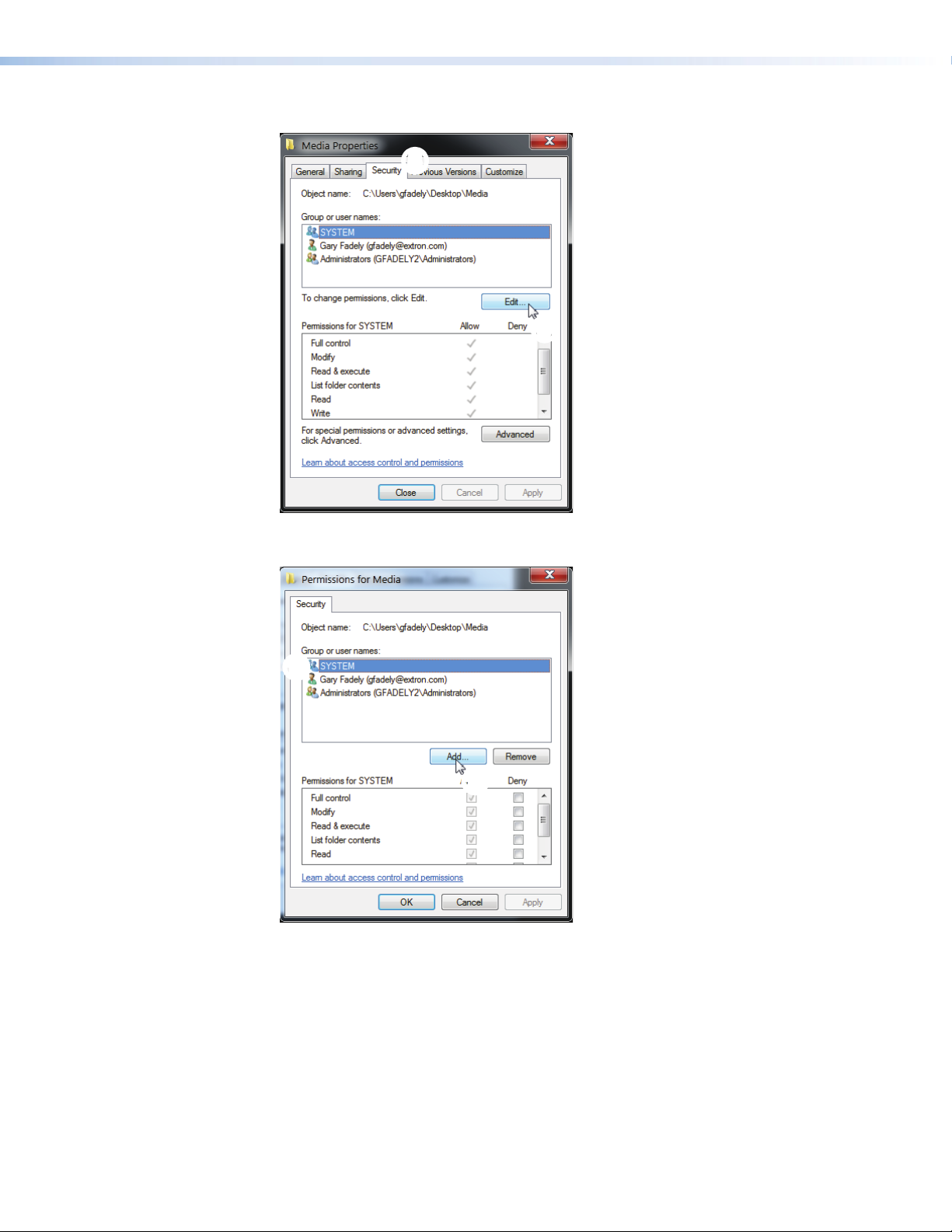
8. In the Media Properties dialog, select the Security tab.
88
9
9
9. In the middle of the dialog, click Edit (see above).
The Permissions for Media dialog box opens.
uu
u
u
10. In the Group or user names: panel, select System, then click Add.
SMD101 • Reference Information 88
Page 95

11. In the Enter the object names to select (examples): field, enter Everyone, then
click Check Names. Everyone is underlined.
££
¤
¤
12. Click OK. The Security dialog box opens.
13. In the Permissions for Everyone panel, under the Allow column, if they are not
already, make certain Read & execute, List folder contents, and Read are checked.
¥¥
¦¦¦
¦
14. Click Apply, then OK to exit the Security dialog box.
NOTE: To reduce the chance of unintentional or unauthorized changes, Extron
recommends only Read access to folders and files that are shared on the
network.
SMD101 • Reference Information 89
Page 96

This completes the folder sharing permissions. Close all open dialog boxes.
Next the sharing properties must be configured.
1. In the control panel, click Network and Internet.
2. Click Network and Sharing Center.
3. Click Change advanced sharing settings on the left side of the dialog.
4. Click on the down arrow icon to expand the Home or Work option.
SMD101 • Reference Information 90
Page 97

5. On the expanded Home or Work panel make the following selections:
• Network Discovery = On
• File and Printer Sharing = On
• Public Folder Sharing = On
• File Sharing Connections = Enable File Sharing for Devices that use 40- or 56-
bit encryption.
• HomeGroup Connections = Allow Windows to manage homegroup connections.
• Password Protected Sharing = Off (this selection may or may not be visible).
6. Click Save Changes, then close the control panel.
File and folder sharing is now available on the PC.
SMD101 • Reference Information 91
Page 98

Copying Config Files Using Internet Explorer
Internet Explorer does not automatically save the SMD101 config files to the host computer
(see Configuration panel on page37), but attempts to open them instead. The box.cfg
and ip.cfg files must be saved using a text file copy.
To save a configuration file using IE:
1. Open the web-interface for the SMD101 (see Accessing the Web-based User
Interface on page14).
2. Open the Advanced Configuration page (see Advanced Configuration Page on
page34).
3. Save the box configuration file (see Firmware Loader on page36).
4. When the configuration file is saved, a new browser tab automatically opens and
displays the contents of the configuration text file.
5. Press <CTL+A> (or triple-click anywhere in the text line) to select the entire contents of
the file, then <CTL+C> to copy the full text to the clipboard.
6. Open a text program (such as Notepad) and paste the text line using <CTL+V> or
Edit>Paste from the toolbar.
7. Choose a location for the file, then select File>SaveAs from the toolbar.
8. In the Save As dialog, rename the file box.cfg.
9. Click Save.
User > Downloads
box.cfg
To save the IP configuration file:
1. Repeat steps 1 to 3 choosing the IP Config option in step 3.
2. Continue with steps 4 to 7.
3. Rename the file IP.cfg in step 8.
4. Click Save.
The two files (box.cfg and ip.cfg) are now ready for use.
To return to the SMD101 web interface, click Back in the IE browser.
SMD101 • Reference Information 92
Page 99

DataViewer
DataViewer is an enhanced terminal emulation program that facilitates analysis of RS-232,
USB, and TCP/IP communication with Extron devices. The software allows users to send
commands to a device and view the responses in ASCII or hexadecimal format. Command
and response logs can be saved in text or HTML format.
DataViewer is available at www.extron.com. Download the installation file and load the
program on the PC connected to the SMD101.
Starting the DataViewer program
1. To run the DataViewer Control Program, click
the desktop icon.
2. The communications setup dialog box opens.
a. Select the Comm Port (RS-232) tab (shown
with the correct protocol settings at right) if
using the rear panel RS-232 port, or
ÕÕ
Ü
Ü
4
4
b. Select the USB tab if using the front panel
config port.
3. Select the startup options:
a. If RS-232 is selected, configure the protocol
settings, then click OK to always use this port
and settings when starting the DataViewer
program.
b. If USB is selected, choose Extron USB
Device in the drop-down window and click
OK.
To automatically connect to the SMD101,
select Auto‑connect on startup .
4. Click OK to start using the program.
You are now ready to configure DataViewer or begin
entering commands.
Use the DataViewer help file formore information on
the program.
ÖÖ
Extron USB Device
4
4
ÝÝ
SMD101 • Reference Information 93
Page 100

Glossary
Advanced Audio Coding (AAC) — A standardized compression and encoding scheme for
lossy (low quality) digital audio. Higher bit rates provide higher quality. Part of the MPEG-2
and MPEG-4 specifications. The SMD101 supports AAC-LC (MPEG-2 part 7, MPEG-4
part3, sub-part4 and part 14, MP4 audio).
Advanced Video Coding (AVC) — Video compression format, H.264/MPEG-4 part 10.
See the H.264 (MPEG-4 AVC) definition.
Address Resolution Protocol (ARP) — A protocol for assigning an IP address to a device
based on the device MAC (Media Access Control) address or physical machine address,
that maintains a table showing the correlation between the two.
B-frames — Bi-predictive frames (B-frames) reference video frames before and after the
current frame. They offer significantly better compression than I or P frames, but are not
available in Baseline profile.
Bandwidth — A measure of available (or used) data communication resources. The
total range of frequencies or bit rate required to pass a specific signal without significant
distortion or loss of data. The maximum bit rate at a specified error rate, expressed in
bits per second (bps). The device bandwidth should be wider than the highest possible
bandwidth of the signals it could be required to process.
Bit rate — The number of bits that are conveyed or processed per unit of time. Bit rate is
quantified using the bits per second (bit / s) unit, often in conjunction with an SI prefix such
as kilo- (kbit / s or kbps), mega- (Mbit / s or Mbps), or giga- (Gbit / s or Gbps).
Codec — A hardware device or software program used to encode or decode a digital data
stream or signal. Loosely, a combination of coder-decoder or compressor-decompressor.
Compression — Reducing the amount of data required to represent a picture (or a stream
of pictures) and sound before sending or storing it.
Constant Bit Rate (CBR) — This scheme adjusts the output bit rate so that it stays very
close to the specified target bit rate.
Constrained Variable Bit Rate (CVBR) — This scheme is similar to Variable Bit Rate
(VBR), but sets a maximum allowed bit rate that the encoder cannot exceed.
Data bits — The number of bits used to represent one character of data. Data bits can be
7, 8, or 16, but most serial devices use 8 bits for ASCII characters.
DDC — Display Data Channel (DDC) is a bi-directional communications standard
developed by VESA ( Video Electronics Standards Association) that defines a universal data
transmission standard for the connectivity between display devices and computers.
Decoder — A hardware device or software program used to decompress (decode) or
change a signal from one format to another or convert a digital signal into analog. The
SMD101 is a decoder that converts compatible digital AV streams into a video and audio
HDMI signal or to HDMI AV plus analog audio.
Dynamic Host Configuration Protocol (DHCP) — A network protocol that enables
a server to automatically assign unique network addresses (IP address, subnet mask,
gateway) to a device using a defined range of numbers configured for the network.
Domain Name System (DNS) — A database system that translates domain names
(such as www.extron.com) into IP addresses.
Dynamic IP address — An IP address that is automatically assigned to a client device in a
TCP/IP network, typically by a DHCP server. Network devices that serve multiple user, such
as servers and printers, are usually assigned a static (unchanging) IP address.
SMD101 • Reference Information 94
 Loading...