

Page 1

Firmware Upgrade Procedure
Matrix Switchers
CrossPoint Plus, CrossPoint, MAV, Matrix 50
68-353-06 Rev. B
03 05
Page 2
Firmware Upgrade Procedure, cont’d
Firmware Upgrade Procedure
This procedure details how to replace a CrossPoint Plus, CrossPoint, MAV, or
Matrix 50 firmware IC chip without disconnecting all of the input and output
connections.
The IC that contains the firmware for the matrix switcher also contains the
memory in which presets and audio levels are saved. When you replace the IC,
these settings will be lost. You may want to record the presets and audio levels
before you replace the IC.
Remove Power
Disconnect the power cord from the switcher.
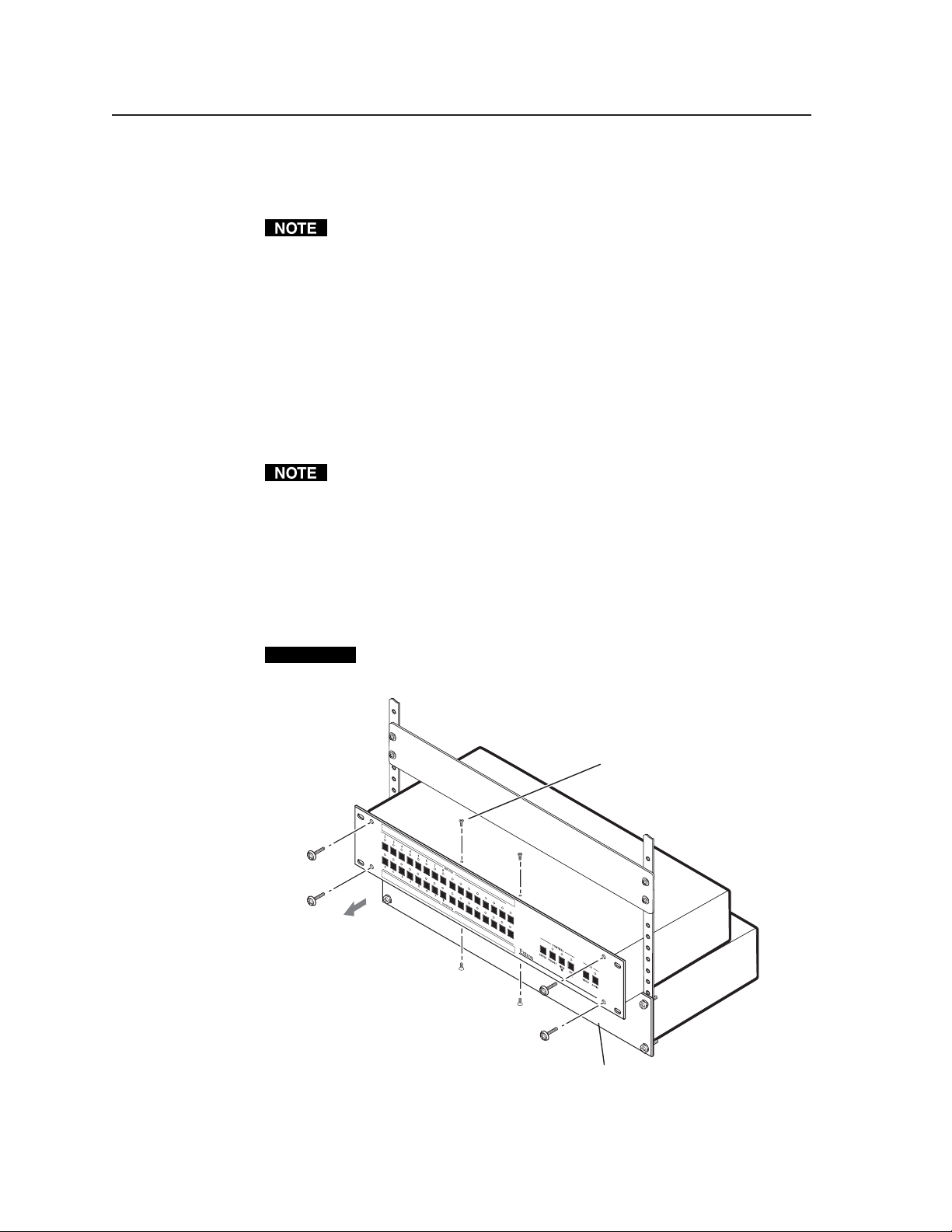
Partially Remove the Switcher from a Rack
To access screws on some switcher models and to make room for the front panel on
other switcher models, the matrix switcher to be upgraded should be partially
removed from its equipment rack as follows:
If the matrix switcher is not on the bottom of the rack or directly above another
device, Extron recommends temporarily installing a device in the rack directly
below the matrix switcher to be upgraded to support the weight of the switcher
during this procedure.
1. Remove the machine screws that secure the switcher to the rack.
2. Carefully pull the switcher forward 1" (2.5 cm) (figure 1). If your switcher has
screws on the top and bottom that need to be removed, give yourself just
enough room to access the screws on the top and bottom of the front of the
switcher.
CAUTION
Do not pull the switcher far enough forward that you strain the input,
output, or other cables on the rear of the switcher.
Remove two screws from top
and bottom (if present) and
four or ten screws from
the front panel.
91
01
1
1
2
1
3
1
41
1
01
11
5
1
6
2
1
31
4
1
5
1
6
M
A
V
S
ER
IE
S S
C
O
W
M
I
TC
P
O
H
S
I
E
TE
R
V
I
D
EO
9
Pull the switcher out
of the rack one inch.
Use another device to support
the switcher’s weight.
Figure 1 — Partially removing the matrix switcher from a rack and
removing the front panel
CrossPoint Plus/CrossPoint/MAV/Matrix 50 • Firmware Upgrade Procedure2
Page 3

Remove the front panel
Before you can replace the firmware IC, you must remove the matrix switcher’s
front panel as follows:
Power must be disconnected the cord from the switcher.
1. If the switcher has screws on its top and bottom, remove the two top and
bottom screws (four screws total) on the front of the switcher (figure 1).
These screws are present and need to be removed only if the matrix switcher
to be updated is
• CrossPoint Plus 168 • CrossPoint Plus 1616
• CrossPoint 168 • CrossPoint 1616
2. Remove the four or ten (depending on the switcher model) that secure the
switcher’s front panel in place.
3. Carefully tilt the front panel away from the main body of the switcher.
CAUTION
4. On the front panel board, press the two receptacle tabs
on the top cable outward as shown at the right, and pull
back gently on the cable connector to remove it from the
receptacle.
5. Lay the front panel down in front of the switcher.
The reach of the remaining cables connected to the front panel board on
CrossPoint Plus and CrossPoint 1616 and 168 switchers is just barely long
enough. Slightly lift the front of the switcher and slide the panel under the
switcher as you tip it away from the switcher.
not one of the following models:
Do not touch the firmware IC or the components inside the switcher
without being electrically grounded. Electrostatic discharge (ESD) can
damage ICs, even if you cannot feel, see, or hear it.
Ribbon cable
Connector
Self-latching receptacle
Replace the Firmware IC
Replace the firmware IC as follows:
1. Locate IC U7 (figure 2) on the front panel board.
2. Use a PLCC IC puller to remove the existing firmware IC.
Squeeze the tool to align its
hooks with the slots in opposite
corners of socket U7. Insert the
hooks, squeeze gently, and pull
the IC straight out of the socket.
Discard the IC.
Figure 2 — Location of IC U7 on the front panel board
Slots for Removing IC
with PLCC IC Puller
Label includes
Extron part number &
Firmware version (Vx.xx).
Vx.xx
19-nnn-01
nnn
Key
3CrossPoint Plus/CrossPoint/MAV/Matrix 50 • Firmware Upgrade Procedure
Page 4

Firmware Upgrade Procedure, cont’d
3. Note the key (angled corner) of the replacement firmware IC and the dot on
the underside that indicates pin 1 (figure 3). Orient the IC to match the key
and pin 1 (indicated by arrow) on the socket. While you support the front
panel from the bottom, carefully press the IC in place.
Pin 1 mark Pin 1 mark
Key
Key
Socket
IC
Figure 3 — Key and pin 1 mark
Reinstall the Front Panel and Initialize the Switcher
1.
Tip the front panel into position close to the switcher and reinstall the cable
removed in step 4 of Remove the Front Panel.
To plug the self latching cable into the desired receptacle,
align the holes in the connector with the pins in the
receptacle, and press evenly until the receptacle tabs lock
into place.
2. Replace all the front panel screws removed in step 2 of Remove the Front Panel.
3. If top and bottom screws were removed in step 1 of Remove the Front Panel,
replace them.
4. Reinitialize the switcher to recognize the new IC as follows:
a. Press and hold the Enter button while you connect the power cord to the
switcher.
b. Observe that the Input, Output, Preset, View, and Esc LEDs all flash.
c. Release the Enter button.
5. Disconnect the power cord from the switcher.
6. Reset the switcher as follows:
a. Press and hold the Esc button while you connect the power cord to the
switcher.
b. Observe that the Input, Output, Preset, View, and Esc LEDs all flash.
c. Release the Esc button.
7. Ensure that the switcher is working properly.
8. If the switcher was removed from a rack, align the holes in the mounting
bracket with those of the rack. Secure the switcher to the rack using the
machine screws removed in step 1 of Partially Remove the Switcher from a Rack.
Ribbon cable
Self-latching receptacle
CrossPoint Plus/CrossPoint/MAV/Matrix 50 • Firmware Upgrade Procedure4
 Loading...