

Page 1
ISS 506
Integration Seamless Switcher
68-1077-01 Rev. B
06 09
Page 2

Precautions
Safety Instructions • English
This symbol is intended to alert the user of important operating and maintenance
(servicing) instructions in the literature provided with the equipment.
This symbol is intended to alert the user of the presence of uninsulated dangerous
voltage within the product’s enclosure that may present a risk of electric shock.
Caution
Read Instructions • Read and understand all safety and operating instructions before using the equipment.
Retain Instructions • The safety instructions should be kept for future reference.
Follow Warnings • Follow all warnings and instructions marked on the equipment or in the user
information.
Avoid Aachments • Do not use tools or aachments that are not recommended by the equipment
manufacturer because they may be hazardous.
Consignes de Sécurité • Français
Ce symbole sert à avertir l’utilisateur que la documentation fournie avec le matériel
contient des instructions importantes concernant l’exploitation et la maintenance
(réparation).
Ce symbole sert à avertir l’utilisateur de la présence dans le boîtier de l’appareil
de tensions dangereuses non isolées posant des risques d’électrocution.
Attention
Lire les instructions• Prendre connaissance de toutes les consignes de sécurité et d’exploitation avant
d’utiliser le matériel.
Conserver les instructions• Ranger les consignes de sécurité an de pouvoir les consulter à l’avenir.
Respecter les avertissements • Observer tous les avertissements et consignes marqués sur le matériel ou
présentés dans la documentation utilisateur.
Eviter les pièces de xation • Ne pas utiliser de pièces de xation ni d’outils non recommandés par le
fabricant du matériel car cela risquerait de poser certains dangers.
Sicherheitsanleitungen • Deutsch
Dies es Symbol soll dem Benut zer in der im Liefer umfang ent haltenen
Dokumentation besonders wichtige Hinweise zur Bedienung und Wartung
(Instandhaltung) geben.
Dieses Symbol soll den Benutzer darauf aufmerksam machen, daß im Inneren des
Gehäuses dieses Produktes gefährliche Spannungen, die nicht isoliert sind und
die einen elektrischen Schock verursachen können, herrschen.
Achtung
Lesen der Anleitungen • Bevor Sie das Gerät zum ersten Mal verwenden, sollten Sie alle Sicherheits-und
Bedienungsanleitungen genau durchlesen und verstehen.
Auewahren der Anleitungen • Die Hinweise zur elektrischen Sicherheit des Produktes sollten Sie
auewahren, damit Sie im Bedarfsfall darauf zurückgreifen können.
Befolgen der Warnhinweise • Befolgen Sie alle Warnhinweise und Anleitungen auf dem Gerät oder in der
Benutzerdokumentation.
Keine Zusatzgeräte • Verwenden Sie keine Werkzeuge oder Zusatzgeräte, die nicht ausdrücklich vom
Hersteller empfohlen wurden, da diese eine Gefahrenquelle darstellen können.
Warning
Power sources • This equipment should be operated only from the power source indicated on the product. This
equipment is intended to be used with a main power system with a grounded (neutral) conductor. The
third (grounding) pin is a safety feature, do not aempt to bypass or disable it.
Power disconnection • To remove power from the equipment safely, remove all power cords from the rear of
the equipment, or the desktop power module (if detachable), or from the power source receptacle (wall
plug).
Power cord protection • Power cords should be routed so that they are not likely to be stepped on or pinched by
items placed upon or against them.
Servicing • Refer all servicing to qualied service personnel. There are no user-serviceable parts inside. To
prevent the risk of shock, do not aempt to service this equipment yourself because opening or removing
covers may expose you to dangerous voltage or other hazards.
Slots and openings • If the equipment has slots or holes in the enclosure, these are provided to prevent
overheating of sensitive components inside. These openings must never be blocked by other objects.
Lithium baery • There is a danger of explosion if baery is incorrectly replaced. Replace it only with the
same or equivalent type recommended by the manufacturer. Dispose of used baeries according to the
manufacturer’s instructions.
Avertissement
Alimentations• Ne faire fonctionner ce matériel qu’avec la source d’alimentation indiquée sur l’appareil. Ce
matériel doit être utilisé avec une alimentation principale comportant un l de terre (neutre). Le troisième
contact (de mise à la terre) constitue un dispositif de sécurité : n’essayez pas de la contourner ni de la
désactiver.
Déconnexion de l’alimentation• Pour mere le matériel hors tension sans danger, déconnectez tous les cordons
d’alimentation de l’arrière de l’appareil ou du module d’alimentation de bureau (s’il est amovible) ou encore
de la prise secteur.
Protection du cordon d’alimentation • Acheminer les cordons d’alimentation de manière à ce que personne ne
risque de marcher dessus et à ce qu’ils ne soient pas écrasés ou pincés par des objets.
Réparation-maintenance • Faire exécuter toutes les interventions de réparation-maintenance par un technicien
qualié. Aucun des éléments internes ne peut être réparé par l’utilisateur. An d’éviter tout danger
d’électrocution, l’utilisateur ne doit pas essayer de procéder lui-même à ces opérations car l’ouverture ou le
retrait des couvercles risquent de l’exposer à de hautes tensions et autres dangers.
Fentes et orices • Si le boîtier de l’appareil comporte des fentes ou des orices, ceux-ci servent à empêcher
les composants internes sensibles de surchauer. Ces ouvertures ne doivent jamais être bloquées par des
objets.
Lithium Baerie • Il a danger d’explosion s’ll y a remplacment incorrect de la baerie. Remplacer uniquement
avec une baerie du meme type ou d’un ype equivalent recommande par le constructeur. Mere au reut les
baeries usagees conformement aux instructions du fabricant.
Vorsicht
Stromquellen • Dieses Gerät sollte nur über die auf dem Produkt angegebene Stromquelle betrieben werden.
Dieses Gerät wurde für eine Verwendung mit einer Hauptstromleitung mit einem geerdeten (neutralen)
Leiter konzipiert. Der drie Kontakt ist für einen Erdanschluß, und stellt eine Sicherheitsfunktion dar. Diese
sollte nicht umgangen oder außer Betrieb gesetzt werden.
Stromunterbrechung • Um das Gerät auf sichere Weise vom Netz zu trennen, sollten Sie alle Netzkabel
aus der Rückseite des Gerätes, aus der externen Stomversorgung (falls dies möglich ist) oder aus der
Wandsteckdose ziehen.
Schutz des Netzkabels • Netzkabel sollten stets so verlegt werden, daß sie nicht im Weg liegen und niemand
darauf treten kann oder Objekte darauf- oder unmielbar dagegengestellt werden können.
Wartung • Alle Wartungsmaßnahmen sollten nur von qualiziertem Servicepersonal durchgeführt werden.
Die internen Komponenten des Gerätes sind wartungsfrei. Zur Vermeidung eines elektrischen Schocks
versuchen Sie in keinem Fall, dieses Gerät selbst önen, da beim Entfernen der Abdeckungen die Gefahr
eines elektrischen Schlags und/oder andere Gefahren bestehen.
Schlitze und Önungen • Wenn das Gerät Schlitze oder Löcher im Gehäuse aufweist, dienen diese zur
Vermeidung einer Überhitzung der empndlichen Teile im Inneren. Diese Önungen dürfen niemals von
anderen Objekten blockiert werden.
Litium-Baerie • Explosionsgefahr, falls die Baerie nicht richtig ersetzt wird. Ersetzen Sie verbrauchte
Baerien nur durch den gleichen oder einen vergleichbaren Baerietyp, der auch vom Hersteller empfohlen
wird. Entsorgen Sie verbrauchte Baerien bie gemäß den Herstelleranweisungen.
Instrucciones de seguridad • Español
Este símbolo se utiliza para advertir al usuario sobre instrucciones importantes
de operación y mantenimiento (o cambio de partes) que se desean destacar en el
contenido de la documentación suministrada con los equipos.
Este símbolo se utiliza para advertir al usuario sobre la presencia de elementos con
voltaje peligroso sin protección aislante, que puedan encontrarse dentro de la caja
o alojamiento del producto, y que puedan representar riesgo de electrocución.
Precaucion
Leer las instrucciones • Leer y analizar todas las instrucciones de operación y seguridad, antes de usar el
equipo.
Conservar las instrucciones • Conservar las instrucciones de seguridad para futura consulta.
Obedecer las advertencias • Todas las advertencias e instrucciones marcadas en el equipo o en la
documentación del usuario, deben ser obedecidas.
Evitar el uso de accesorios • No usar herramientas o accesorios que no sean especicamente recomendados
por el fabricante, ya que podrian implicar riesgos.
安全须知 • 中文
这个符号提示用户该设备用户手册中有重要的操作和维护说明。
这个符号警告用户该设备机壳内有暴露的危险电 压,有触电危险。
注意
阅读说明书 • 用户使用该设备前必须阅读并理解所有安全和使用说明。
保存说明书 • 用户应保存安全说明书以备将来使用。
遵守警告 • 用户应遵守产品和用户 指南上的所有安全和 操作说明。
避免追加 • 不要使用该产品厂商没有推荐的工具或追加设备,以避免危险。
Advertencia
Alimentación eléctrica • Este equipo debe conectarse únicamente a la fuente/tipo de alimentación eléctrica
indicada en el mismo. La alimentación eléctrica de este equipo debe provenir de un sistema de distribución
general con conductor neutro a tierra. La tercera pata (puesta a tierra) es una medida de seguridad, no
puentearia ni eliminaria.
Desconexión de alimentación eléctrica • Para desconectar con seguridad la acometida de alimentación eléctrica
al equipo, desenchufar todos los cables de alimentación en el panel trasero del equipo, o desenchufar el
módulo de alimentación (si fuera independiente), o desenchufar el cable del receptáculo de la pared.
Protección del cables de alimentación • Los cables de alimentación eléctrica se deben instalar en lugares donde
no sean pisados ni apretados por objetos que se puedan apoyar sobre ellos.
Reparaciones/mantenimiento • Solicitar siempre los servicios técnicos de personal calicado. En el interior no
hay partes a las que el usuario deba acceder. Para evitar riesgo de electrocución, no intentar personalmente
la reparación/mantenimiento de este equipo, ya que al abrir o extraer las tapas puede quedar expuesto a
voltajes peligrosos u otros riesgos.
Ranuras y aberturas • Si el equipo posee ranuras o oricios en su caja/alojamiento, es para evitar el
sobrecalientamiento de componentes internos sensibles. Estas aberturas nunca se deben obstruir con otros
objetos.
Batería de litio • Existe riesgo de explosión si esta batería se coloca en la posición incorrecta. Cambiar esta
batería únicamente con el mismo tipo (o su equivalente) recomendado por el fabricante. Desachar las
baterías usadas siguiendo las instrucciones del fabricante.
警告
电源 • 该设备只能使用产品上标明的电源。 设备必须使用有地线的供电系统供电。 第三条线
(地线)是安全设施,不能不用或跳过 。
拔掉电源 • 为安全地从设备拔掉电源,请拔掉所有设备后或桌面电源的电源线,或任何接到市
电系统的电 源线。
电源线保护 • 妥善布线, 避免被 踩踏,或重物 挤压。
维护 • 所有维修必须由认证的维修人员进行。 设备内部没有用户可以更换的零件。为避免出现
触电危险不要自己试图打开设备盖子维修该设备。
通风孔 • 有些设备机壳 上有通风槽或孔,它们是用来防止机内敏感元件过热。 不要用任何东
西挡住通风 孔。
锂电池 • 不正确的更换电池会有爆炸的危险。必须使用与厂家推荐的相同或相近型号的电池。
按照生 产厂的建议处 理废弃电池。
Page 3

FCC Class A Notice
This equipment has been tested and found to comply with the limits for a Class A digital device, pursuant to part 15 of the FCC Rules. Operation is subject to
the following two conditions: (1) this device may not cause harmful interference, and (2) this device must accept any interference received, including interference
that may cause undesired operation. The Class A limits are designed to provide reasonable protection against harmful interference when the equipment is
operated in a commercial environment. This equipment generates, uses, and can radiate radio frequency energy and, if not installed and used in accordance with
the instruction manual, may cause harmful interference to radio communications. Operation of this equipment in a residential area is likely to cause harmful
interference, in which case the user will be required to correct the interference at his own expense.
N
This unit was tested with shielded cables on the peripheral devices. Shielded cables must be used with the unit to ensure compliance with FCC emissions limits.
Page 4

Page 5

Table of Contents
Chapter One • Introduction ......................................................................................................1-1
About this Manual .....................................................................................................................1-2
About the Integration Seamless Switchers ...............................................................1-2
Features ............................................................................................................................................1-4
Chapter Two • Installation ........................................................................................................2-1
Mounting the Switcher ..........................................................................................................2-2
Tabletop placement .................................................................................................................. 2-2
Rack mounting ..........................................................................................................................2-2
UL guidelines .......................................................................................................................2-2
Mounting instructions .........................................................................................................2-3
Cabling and Rear Panel Views............................................................................................2-4
Input connections .....................................................................................................................2-4
Video input connections
Audio input connections
Output connections .................................................................................................................. 2-6
Video output connections
Optional video output connections
Audio output connections
Control connections ..................................................................................................................2-8
Ethernet connection ............................................................................................................2-8
Cabling and RJ-45 connector wiring ..................................................................................2-8
Choosing a network cable .............................................................................................2-9
Wiring the network cable .............................................................................................2-9
Serial port connection ....................................................................................................... 2-10
Reset button ............................................................................................................................2-10
.....................................................................................................2-4
.....................................................................................................2-5
...................................................................................................2-6
...................................................................................2-6
..................................................................................................2-8
Front Panel Configuration Port .......................................................................................2-11
Configuration .............................................................................................................................2-12
Chapter Three • Operation ........................................................................................................ 3-1
Front Panel Controls and Indicators ...............................................................................3-2
Freeze, input selection, Logo/Black, and Cut/Dissolve controls .........................................3-2
Picture adjustment and menu system controls ..................................................................... 3-3
Menu system overview ............................................................................................................. 3-4
Auto Image menu................................................................................................................3-6
Select Output submenu ................................................................................................. 3-6
Input Configuration menu .................................................................................................. 3-6
Input format submenu ..................................................................................................3-7
Audio Level submenu .................................................................................................... 3-8
Film Mode submenu ...................................................................................................... 3-8
Vertical Start and Horizontal Start submenus..............................................................3-8
Preview and Program Phase submenus ........................................................................ 3-9
Total Pixels submenu ..................................................................................................... 3-9
Active Pixels and Active Lines submenus ....................................................................3-10
ISS 506 Integration Seamless Switcher • Table of Contents
i
Page 6

Table of Contents, cont’d
Output Configuration menu.............................................................................................3-11
Resolution and refresh rate submenu ........................................................................ 3-12
Output Type submenu ................................................................................................. 3-13
Sync Polarity submenu .................................................................................................3-13
Effects Configuration menu ..............................................................................................3-13
Dissolve Configuration submenu ................................................................................ 3-14
Wipe Configuration submenu ....................................................................................3-14
Title Key submenu .......................................................................................................3-14
PIP Configuration submenu ........................................................................................3-14
PIP Border Color submenu ..........................................................................................3-15
PIP Audio submenu ......................................................................................................3-15
Logo Capture menu...........................................................................................................3-16
Image Source submenu ...............................................................................................3-16
Capture Start submenu ...............................................................................................3-16
Capture Size
Save Capture to File
User Presets menu .............................................................................................................3-18
Save submenu ..............................................................................................................3-18
Erase submenu ............................................................................................................. 3-19
Advanced Configuration menu ........................................................................................3-19
Auto Image submenu .................................................................................................. 3-20
Test Pattern submenu ..................................................................................................3-20
Blue Mode submenu ....................................................................................................3-21
RGB Delay submenu ....................................................................................................3-21
Auto Memories submenu ............................................................................................ 3-21
Preview Switch Mode submenu .................................................................................. 3-22
Reset submenu ............................................................................................................. 3-22
View and Edit Communications Settings menu ...............................................................3-23
Serial Port submenu .....................................................................................................3-23
MAC Address display ...................................................................................................3-24
DHCP Mode submenu ..................................................................................................3-24
IP Address, Subnet Mask, and Gateway Address submenus .....................................3-24
Scan Converter Configuration menu................................................................................3-25
Size submenu ...............................................................................................................3-25
Center submenu ...........................................................................................................3-25
Output Format submenu .............................................................................................3-26
Output Standard submenu .........................................................................................3-26
Flicker Filter submenu .................................................................................................3-26
Horizontal Filter submenu ..........................................................................................3-26
Encoder Filter submenu ...............................................................................................3-26
Exit menu ........................................................................................................................... 3-27
submenu ................................................................................................. 3-17
submenu ....................................................................................3-17
Front Panel Operations .........................................................................................................3-27
Power-on indications .............................................................................................................. 3-27
Selecting an input to be the program output .................................................................... 3-28
Selecting an input to be the preview output and
switching it to the program output ..................................................................................... 3-29
Recalling a user preset ...........................................................................................................3-30
Capturing a logo .....................................................................................................................3-31
Configuring a logo..................................................................................................................3-33
Configuring a title ..................................................................................................................3-35
Adjusting the picture..............................................................................................................3-36
ii
ISS 506 Integration Seamless Switcher • Table of Contents
Page 7

Toggling background illumination on and off ...................................................................3-37
Using front panel security lockouts (executive modes) ..................................................... 3-38
Rear Panel Reset Button ......................................................................................................3-39
Performing soft system resets ...............................................................................................3-39
Performing a hard reset .........................................................................................................3-41
Optimizing the Video .............................................................................................................3-41
Setting up a DVD source ........................................................................................................ 3-42
Optimizing the Audio ............................................................................................................ 3-42
Troubleshooting ........................................................................................................................3-43
General checks ......................................................................................................................... 3-43
Specific problems ....................................................................................................................3-44
Chapter Four • SIS Programming and Control ............................................................ 4-1
Serial Links .....................................................................................................................................4-2
Rear panel RS-232/RS-422 port ................................................................................................ 4-2
Front panel Configuration port .............................................................................................. 4-3
Ethernet Link ................................................................................................................................4-4
Ethernet connection ................................................................................................................. 4-4
Default address .........................................................................................................................4-4
Symbols ............................................................................................................................................4-5
Switcher-Initiated Messages ............................................................................................... 4-6
Power-up .................................................................................................................................... 4-6
Input selection ........................................................................................................................... 4-6
Effect selection .......................................................................................................................... 4-6
Dissolve ................................................................................................................................4-6
Wipe ..................................................................................................................................... 4-6
Title .......................................................................................................................................4-7
PIP .........................................................................................................................................4-7
Take and busy ............................................................................................................................4-7
Wiping or dissolving in stay mode .....................................................................................4-7
Cutting or dissolving in swap mode ................................................................................... 4-8
Switching in a PIP window or title .....................................................................................4-8
Input and output video type ...................................................................................................4-8
Picture adjustments .................................................................................................................. 4-9
RGB delay .................................................................................................................................4-10
Test pattern .............................................................................................................................. 4-10
Audio gain and attenuation .................................................................................................4-10
Preview switch mode .............................................................................................................. 4-10
PAL film mode .........................................................................................................................4-10
Automated adjustments ........................................................................................................4-10
Host-to-Switcher Instructions ...........................................................................................4-11
Switcher Error Responses ...................................................................................................4-11
ISS 506 Integration Seamless Switcher • Table of Contents
iii
Page 8

Table of Contents, cont’d
Using the Command/Response Tables ......................................................................... 4-11
Command/response table for SIS commands ......................................................... 4-12
Command/Response Table for IP SIS Commands .................................................4-35
Symbol definitions ..................................................................................................................4-35
Special Characters ...................................................................................................................4-38
Chapter Five • Switcher Software ........................................................................................ 5-1
ISS 506 Control Program ........................................................................................................5-2
Installing the software .............................................................................................................5-2
Software operation via Ethernet ............................................................................................5-3
Ethernet protocol settings ..................................................................................................5-3
Using the software....................................................................................................................5-4
Control window ........................................................................................................................5-5
I/O Configuration window ....................................................................................................... 5-8
Logo Setup/Capture window ..................................................................................................5-9
Capturing a logo..................................................................................................................5-9
Recalling and configuring a logo .....................................................................................5-10
Advanced Setup window ....................................................................................................... 5-12
Scan Converter Setup window .............................................................................................. 5-13
System Settings windows ....................................................................................................... 5-13
System Settings IP settings window .................................................................................5-14
Unit Name field ............................................................................................................5-14
Use DHCP checkbox .....................................................................................................5-14
MAC Address field .......................................................................................................5-14
IP Address field ............................................................................................................5-14
Gateway field ............................................................................................................... 5-15
Subnet Mask field ........................................................................................................ 5-15
Mail Server IP Address field .........................................................................................5-15
Mail Server User Name field ........................................................................................5-15
Mail Server Domain Name field .................................................................................. 5-15
Mail Server User Password field .................................................................................. 5-15
System Settings RS-232 window .......................................................................................5-16
Baud Rate dropbox ...................................................................................................... 5-16
System Settings Date/Time window .................................................................................5-17
Sync Date & Time to PC button ...................................................................................5-17
Date field......................................................................................................................5-17
Time (local) field ..........................................................................................................5-18
Daylight Savings check box ......................................................................................... 5-18
System Settings Passwords window .................................................................................5-18
Updating firmware .................................................................................................................5-19
Uploading images ................................................................................................................... 5-22
Windows menus ...................................................................................................................... 5-24
File menu
Options menu .................................................................................................................... 5-24
Tools menu .........................................................................................................................5-25
Help menu
Using the help system ............................................................................................................5-27
...........................................................................................................................5-24
.........................................................................................................................5-26
iv
ISS 506 Integration Seamless Switcher • Table of Contents
Page 9

Button Label Generator .......................................................................................................5-27
Using the Button Label Generator software ......................................................................5-27
Special Characters ...................................................................................................................5-28
Chapter 6 • HTML Operation ..................................................................................................... 6-1
Downloading the Startup Page ......................................................................................... 6-2
System Status Tab ...................................................................................................................... 6-3
Configuration Tab ...................................................................................................................... 6-4
System Configuration page ..................................................................................................... 6-4
IP Settings fields ..................................................................................................................6-4
Unit Name field ..............................................................................................................6-4
DHCP radio buttons
IP Address field ..............................................................................................................6-5
Gateway IP Address field ...............................................................................................6-5
Subnet Mask field .......................................................................................................... 6-5
MAC Address field .........................................................................................................6-5
Date/Time Settings fields ....................................................................................................6-5
ISS Settings page .......................................................................................................................6-6
Scan converter board page ......................................................................................................6-7
Passwords page .........................................................................................................................6-8
Email Alerts page ...................................................................................................................... 6-9
Setting up e-mail alerts .......................................................................................................6-9
Setting up SMTP authorization ........................................................................................6-10
Firmware Upgrade page ........................................................................................................ 6-10
....................................................................................................... 6-4
File Management Tab ............................................................................................................6-12
File Management page ..........................................................................................................6-12
Control Tab ...................................................................................................................................6-13
User Control page ................................................................................................................... 6-13
Preset page ..............................................................................................................................6-14
User presets ........................................................................................................................ 6-14
Input presets ...................................................................................................................... 6-15
PIP settings page .....................................................................................................................6-15
Logos page ...............................................................................................................................6-16
Uploading an image .......................................................................................................... 6-16
Deleting an image .............................................................................................................6-17
Assigning (recall) a logo .................................................................................................... 6-17
Configuring a logo ............................................................................................................6-17
Special Characters ...................................................................................................................6-18
ISS 506 Integration Seamless Switcher • Table of Contents
v
Page 10

Table of Contents, cont’d
Chapter 7 • Modifications ........................................................................................................... 7-1
Opening the Switcher ..............................................................................................................7-2
Installing an Optional SDI/HD-SDI Input Board .......................................................7-3
Installing an Optional Output Board ............................................................................. 7-6
Closing the Switcher .............................................................................................................. 7-10
Button Labels .............................................................................................................................. 7-10
Installing labels in the switcher’s buttons ...........................................................................7-10
Button label blanks ................................................................................................................. 7-11
Appendix A • Ethernet Connection .................................................................................... A-1
Ethernet Link ............................................................................................................................... A-2
Ethernet connection ................................................................................................................ A-2
Default address ........................................................................................................................ A-2
Ping to determine Extron IP address ................................................................................. A-2
Ping to determine Web IP address .................................................................................... A-3
Connect as a Telnet client ....................................................................................................... A-3
Telnet tips
............................................................................................................................ A-4
Open .............................................................................................................................. A-4
Escape character and Esc key ....................................................................................... A-4
Local echo ...................................................................................................................... A-5
Set carriage return-line feed ........................................................................................ A-5
Close .............................................................................................................................. A-5
Help ............................................................................................................................... A-5
Quit ................................................................................................................................ A-5
Subnetting — A Primer .......................................................................................................... A-6
Gateways ................................................................................................................................... A-6
Local and remote devices ........................................................................................................ A-6
IP addresses and octets ............................................................................................................ A-6
Subnet masks and octets ......................................................................................................... A-6
Determining whether devices are on the same subnet ..................................................... A-7
Appendix B • Reference Information ................................................................................B-1
Specifications ...............................................................................................................................B-2
Part Numbers and Accessories ...........................................................................................B-5
ISS 506 part numbers ................................................................................................................B-5
Included parts ............................................................................................................................B-5
Accessories .................................................................................................................................B-5
All trademarks mentioned in this manual are the properties of their respective owners.
68-1077-01 B
06 09
vi
ISS 506 Integration Seamless Switcher • Table of Contents
Page 11

ISS 506 Integration Seamless Switcher
Chapter One
1
Introduction
About this Manual
About the Integration Seamless Switchers
Features
Page 12

Introduction
About this Manual
This manual contains installation, configuration, and operating information for the
Extron ISS 506 family of 6-input Integration Seamless Switchers with audio.
About the Integration Seamless Switchers
The Extron ISS 506 is a family of scaling, video and stereo audio seamless switchers.
The ISS 506 family consists of the following five models:
• ISS 506 — Six-input seamless video switcher with audio
• ISS 506 DI/DVI — Six-input seamless video switcher with audio,
• ISS 506 SC — Six-input seamless video switcher with audio and
• ISS 506 DI/SC — Six-input seamless video switcher with audio, SDI/HD-SDI
•
N
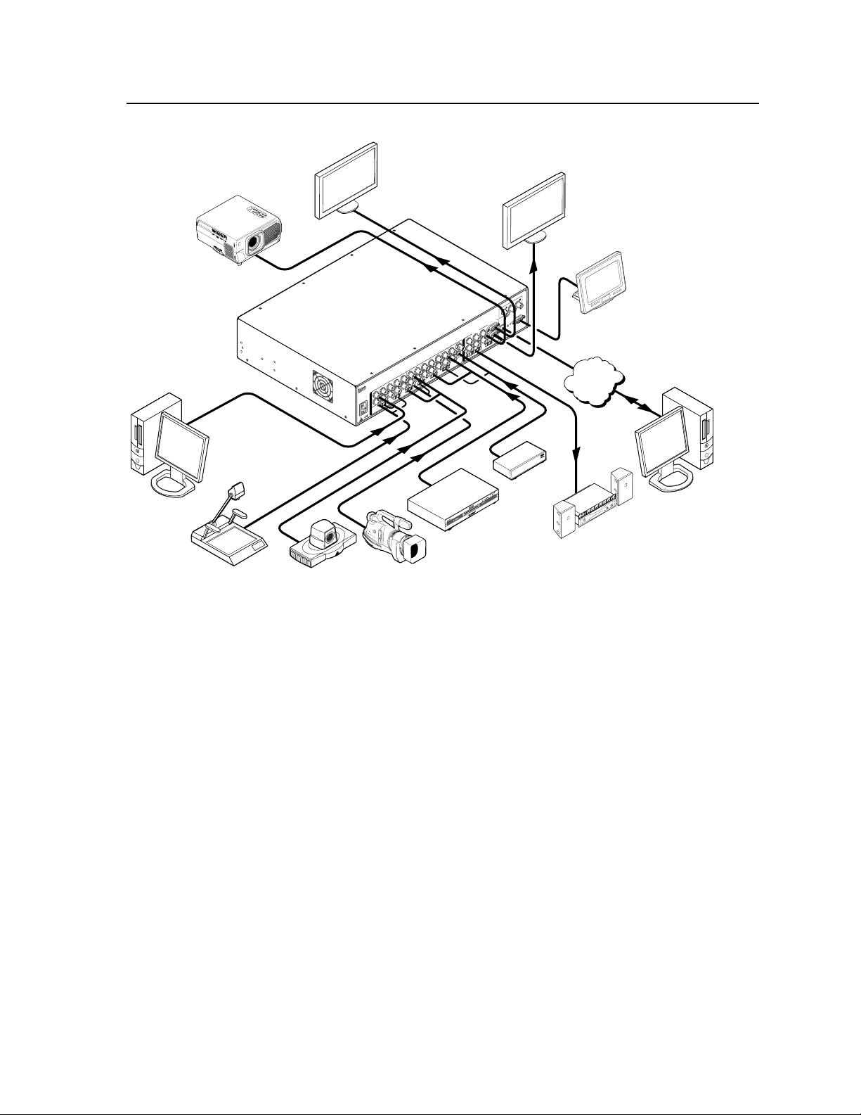
Figure 1-1 on the next page shows a typical ISS 506 application. The switchers
accept up to six video and stereo inputs of various resolutions, scale the video
inputs, and output RGB or YUV video and audio. The scaler can input high
resolution video and/or low resolution video in the following formats:
SDI/HD-SDI video input, and digital visual interface (DVI) video output
scan-converted output
video input, and scan-converted output
ISS 506 DI/HD-SDI — Six-input seamless video switcher with audio,
SDI/HD-SDI video input, and HD-SDI output
In this manual, the terms “ISS 506” and “switcher“ refer to any of the above
models unless otherwise stated.
RGB (RGBHV, RGBS, RGBcvS) video
•
YUV-HD (HDTV) video
•
Progressive YUV component video
•
Interlaced YUV component video
•
S-video (Y/C)
•
Composite (NTSC, PAL, SECAM) video
•
SDI/HD-SDI video (scalers with an optional SDI board only)
•
The ISS seamlessly switches between the program and preview inputs without a
loss of sync. The ISS can also mask the switch between sources with a dissolve
or one of a variety of other transition effects for a professional look. The audio
transition can also be accompanied by either a cut or a cross fading effect.
Each video input is individually configurable to allow for different video formats.
The ISS allows the various high-resolution and low-resolution video formats to
be displayed on a device with a fixed resolution and aspect ratio, such as a liquid
crystal display (LCD) projector, a digital light processor (DLP) projector, a plasma
display, or, optionally, a DVI or HD-SDI device.
The ISS provides two separate outputs: the program output and the preview output.
The program output is the picture the audience sees. The preview output allows
the switcher operator to view the image before it is sent to the program output
for the audience to see. With an optional HD-SDI, DVI, or scan converter output
board, the ISS converts the scaled image to digital video or low resolution video as
an additional program output.
1-2
ISS 506 Integration Seamless Switcher • Introduction
Page 13
10
0-240V
50/60 H
z
2A
M
AX
R
/
R
-Y
SDI
G
/Y
V
ID
S
B
/C
B
-Y
H
H
V
/V
V
H
/H
V
R
S23
2/422
1
L
R
R
/
R
-Y
1
2
G
/Y
V
ID
B
/C
B
-Y
R
/
R
-Y
G
/Y
V
ID
B
/C
B
-Y
H
V
/V
V
H
/H
V
V
R
/
R
-Y
3
4
G
/Y
V
ID
B
/C
B
-Y
V
ID
/Y
R
-Y
VID
B
-Y
/C
V
G
/Y
5
R
R-Y
LAN
RESET
O
U
T
P
U
T
S
6
YC
B
/
B
-Y
P
R
O
G
R
A
M
P
R
E
V
I
E
W
R
G
B
/R
-Y
,
Y
,
B
-Y
R
G
B
/R
-Y
,
Y
,
B
-Y
2
L
R
3
L
R
4
L
R
5
L
R
6
L
R
I
N
P
U
T
S
L
R
P
R
E
V
I
E
W
FIXED
L
R
P
R
O
G
R
A
M
VAR
IABLE
L
R
VID
R-Y/
R
B-Y/
B
Y/
G
SC
A
N
CO
NV
ER
T
ED
O
UTPU
T
C
Y
RES
E
T
LAN
Extron
ISS 506
Seamless Switcher
Control System
with RS-232
Ethernet
Sound System
PC
PC
DVD/VCR
TV Tuner
Document Camera
Camera
Codec
LCD Display
(program)
LCD Display
(preview)
Projector
TCP/IP
Network
Figure 1-1 — Typical ISS 506 Integration Seamless Switcher application
The switcher inputs all video signal formats on a combination of connectors as
follows:
• Inputs 1 through 4 — Four sets of five BNC connectors that can input
RGBHV, RGBS, YUV-HD, YUVp, RGBcvS, YUVi, S-video, or composite video
• Input 5 — Three BNC connectors that can input YUVi, S-video, or composite
video
• Input 6 — Either a BNC connector that receives composite video or a 4-pin
mini DIN connector that receives S-video
• Optional input 6 — With an optional board, an optional BNC connector can
receive SDI or HD-SDI video.
The ISS 506 scales the input up or down to any of a wide variety of output
resolutions and rates. The scaler outputs the scaled video as RGBHV, RGBS, or
component video on two sets of program connectors (five BNC connectors and a
15-pin HD connector) and one 15-pin HD preview connector. The program output
BNC connectors and 15-pin HD connector share identical outputs. With one of
three optional output boards, the scaler can also have a third program output,
either:
• DVI video on a DVI connector
• Scan converted video on three BNC connectors
• HD-SDI digital video on a BNC connector (720p and 1080i)
The ISS 506 features HDTV 480p, 576p, 720p, 1080i, and 1080p outputs.
ISS 506 Integration Seamless Switcher • Introduction
1-3
Page 14

Introduction, cont’d
The ISS receives and outputs the stereo audio on 5-pole captive screw connectors.
The audio can be switched with cross fading (that is, the previous audio channel
fades out and then the new audio channel fades in).
For upscaling, the ISS 506 converts the horizontal and vertical sync timing and the
number of lines of the lower-resolution video input to match the native resolution
of the display. This produces an undistorted, brighter picture than an unscaled
input would.
For downscaling, the ISS 506 accepts any computer resolution up to 1600 x 1200,
with horizontal scan rates up to 100 kHz and vertical scan rates up to 120 Hz. The
ISS converts the input to match the native resolution of the display.
The switcher is ideal for displaying images on projectors with limited display
resolutions, such as LCD projectors, DLP projectors, plasma projectors, and (with
an optional DVI board) a DVI display or projector.
The switcher features built-in test patterns to aid in monitor or projector setup and
evaluation.
The switcher is housed in a rack-mountable, 2U high, 17.5" wide, metal enclosure.
The ISS has an internal 100 VAC to 240 VAC, 50-60 Hz, 45 watts internal power
supply that provides worldwide power compatibility.
Features
Inputs —
Video inputs — The ISS switches among six configurable RGB, HDTV
component video, component video, S-video, and composite video inputs.
Optional video input board — With an optional SDI/HD-SDI input board, an
HD-SDI or SDI video signal can be applied to input 6, in place of the S-video
or composite video input.
Audio inputs — The ISS switches among six balanced or unbalanced stereo or
mono audio inputs on 5-pole captive screw connectors.
Outputs —
Standard video outputs — The ISS outputs individually scaled video signals as
RGBHV, RGBS, or component video. One set of BNC connectors and one
15-pin HD connector are provided for the program output. One 15-pin HD
connector is provided for the preview output.
Optional video output daughterboards — With an optional DVI, HD-SDI, or
scan converter output board, an additional program video output is available,
based on the board installed:
• DVI board — The ISS outputs a single loop of DVI-D on a DVI connector.
The DVI output resolution follows the program output.
• HD-SDI board — The ISS outputs an HD-SDI video signal, 1080i or 720p,
on a BNC connector.
N
N
You must set the output rate to 720p (at 25, 30, 50, 59.94, or 60 Hz), 1080i
(at 50, 59.94 or 60 Hz), or 1080p (at 24, 25, or 30 Hz) to activate the HD-SDI
output.
• Scan converter board — The ISS outputs a scan-converted video signal
(low resolution RGsB, component video, S-video, or composite video) on
three BNC connectors.
The scan converter output board can output S-video and composite video
simultaneously.
1-4
ISS 506 Integration Seamless Switcher • Introduction
Page 15

Audio outputs — The ISS outputs the selected unamplified, line level, balanced
or unbalanced stereo or mono audio on 5-pole captive screw connectors.
Operational flexibility — Operations such as input selection, transitions, and
picture adjustments, and volume control can be performed on the front panel
or via the Ethernet or serial link. The serial links allow remote control via a
PC or control system. The Ethernet link allows multiple remote links with
two levels of password protection.
• Front Panel Controller — The front panel controller supports all ISS 506
functions. The input buttons can be labeled with text or graphics.
• Windows-based control program — For serial port or Ethernet remote
control from a PC, the Extron Windows-based control software provides a
graphical interface and drag-and-drop/point-and-click operation.
• Simple Instruction Set (SIS
SIS for easy programming and operation.
• Remote control panels — The switcher is are remote controllable, using the
optional RCP 2000 Remote Control panel.
3:2 pulldown detection for NTSC and 2:2 film detection for PAL video sources —
These advanced film mode processing features help maximize image detail
and sharpness for video sources that originated from film. When film is
converted to NTSC video, the film frame rate has to be matched to the video
frame rate in a process called 3:2 pulldown. Jaggies and other image artifacts
can result if conventional de-interlacing techniques are used on film-source
video. The ISS’s advanced film mode processing recognizes signals that
originated from film. The ISS then applies video processing algorithms
that optimize the conversion of video that was made with the 3:2 pulldown
process. This results in richly detailed images with sharply defined lines.
A similar 2:2 pulldown process is used for PAL film-source video.
Audio follow and breakaway — Audio switching can follow its corresponding
video input signal or it can be broken away from the video input. Audio
breakaway switching can be done under RS-232/RS-422 or Ethernet remote
control.
Audio gain/attenuation — Users can set the input level of audio gain or
attenuation (-18 dB to +24 dB) via the RS-232/RS-422 or Ethernet link, or from
the front panel. Individual input audio levels can be adjusted so there are no
noticeable volume differences between sources.
Audio cross-fading — A transition technique that is applied during the switches.
It lowers the audio level of the switched out source while simultaneously
raising the audio level of the activated source.
Logos — The ISS can display one or two logos on the preview and program
outputs. The ISS can store up to 16 MB of bimapped logos.
Image (logo) save and recall — The ISS can capture an input image and save it for
use as a logo.
Picture-in-picture and title — The ISS can display the preview input on top of the
program output as either a picture-in-picture (PIP) window or a title.
LAN port — Supports connection to an Ethernet LAN so that the switcher can be
accessed and operated anywhere in the world from a computer running a
standard Internet browser.
Quad-standard video decoder — The switcher uses a digital, four-line adaptive
comb filter that can decode NTSC 3.58, NTSC 4.43, PAL, and SECAM signals.
™
) — The remote control protocol uses Extron’s
ISS 506 Integration Seamless Switcher • Introduction
1-5
Page 16

Introduction, cont’d
Transitions — Control the type of switch that occurs between the preview and
program outputs. The Cut button creates an instant switch between the
preview and program outputs. The Wipe and Dissolve buttons switch with a
masking effect.
Test patterns — The switcher features built-in test patterns to aid in monitor or
projector setup and evaluation.
Blue mode — The switcher can be set to output the blue video signal only, to help
installers calibrate the monitor or projector.
Triple-Action Switching
planes to blank the screen while the scaler locks to the new sync, so that
a noise-filled scramble is not shown on the monitor during the transition.
The time delay between the RGB and sync signals is user adjustable up to
5 seconds under front panel, SIS, and program control.
Auto memories — The six inputs support 16 auto-recall memories each, based on
the incoming frequency. Information on sizing, centering, detail, contrast,
and brightness is saved. Auto memories can be turned off under advanced
configuration.
Auto Image
selected input to fill the screen. You can select auto imaging for individual
inputs as desired or set to automatically size and center each new input
selection.
Input presets — The ISS 506 has memory for up to 128 presets that allow the
user to use SIS commands to save and recall color, tint, contrast, brightness,
centering, sizing, and filtering information.
User presets — Three presets for each input save different settings for color, tint,
contrast, brightness, detail, size, centering, and input configurations.
Freeze mode — Locks the output display to the selected image. Once the display
is frozen, you can remove an input without losing the output image. This
feature lets the ISS function as a still store.
Rack mountable — The 2U high switcher can be mounted in any conventional 19"
wide rack.
™
(RGB delay) — RGB delay mutes the R, G, and B video
™
— The auto imaging feature automatically sizes and centers the
1-6
ISS 506 Integration Seamless Switcher • Introduction
Page 17

ISS 506 Integration Seamless Switcher
Chapter Two
2
Installation
Mounting the Switcher
Cabling and Rear Panel Views
Front Panel Configuration Port
Configuration
Page 18

Installation
Mounting the Switcher
Four uninstalled rubber feet are included with the seamless switcher. If you
are going to rack mount the switcher, mount it before you cable it (see “Rack
mounting”, below), and do not install the rubber feet. If you are not rack mounting
the seamless switcher, see “Tabletop placement”, below.
Tabletop placement
For tabletop placement, install the self-adhesive rubber feet/pads (provided) onto
the four corners of the bottom of the seamless switcher.
Rack mounting
UL guidelines
The following Underwriters Laboratories (UL) guidelines pertain to the installation
of the ISS 506 into a rack (figure 2-1).
1. Elevated operating ambient temperature — If the equipment installed in a
2. Reduced air flow — Install the equipment in a rack so that the amount of air
3. Mechanical loading — Mount the equipment in the rack so that a hazardous
4. Circuit overloading — Connect the equipment to the supply circuit and
5. Reliable earthing (grounding) — Maintain reliable grounding of rack-
closed or multi-unit rack assembly, the operating ambient temperature of the
rack environment may be greater than room ambient temperature. Therefore,
install the ISS in an environment compatible with the maximum ambient
temperature (Tma = +122 °F, +50 °C) specified by Extron.
flow required for safe operation of the equipment is not compromised.
condition is not achieved due to uneven mechanical loading.
consider the effect that circuit overloading might have on overcurrent
protection and supply wiring. Appropriate consideration of equipment
nameplate ratings should be used when addressing this concern.
mounted equipment. Pay particular attention to supply connections other
than direct connections to the branch circuit (e.g. use of power strips).
2-2
ISS 506 Integration Seamless Switcher • Installation
Page 19
MBD 249
2-U Rack Mount
Bracket (use four
lower holes)
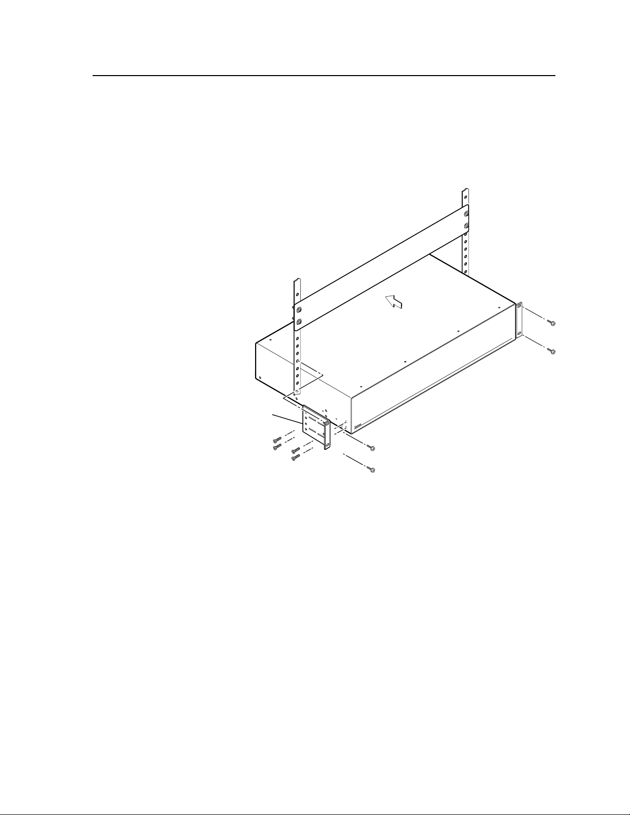
Mounting instructions
For optional rack mounting, do not install the rubber feet. Mount the ISS 506 in a
rack as follows:
1
. Attach the included MBD 249 rack/through-desk mounting brackets to the
unit, using eight machine screws supplied with the mounting kit (figure 2-1).
Use the lower screw holes in the brackets.
Figure 2-1 — Mounting the seamless switcher
2. Insert the unit into the rack and align the holes in the mounting brackets with
the holes in the rack. Use four machine screws to attach the brackets to the
rack.
ISS 506 Integration Seamless Switcher • Installation
2-3
Page 20
Installation, cont’d
100-240V
50/60 Hz
2A MAX
R/
R-Y
SDI
G/Y
VID
S
B/C
B-Y
H
H/HV
V
H/HV
RS232/422
1
L
R
R/
R-Y
1
2
G/Y
VID
B/C
B-Y
R/
R-Y
G/Y
VID
B/C
B-Y
H/HV
V
H/HV
V
V
R/
R-Y
3
4
G/Y
VID
B/C
B-Y
VID
/Y
R-Y
VID
B-Y
/C
V
G
/Y
5
R
R-Y
RESET
O
U
T
P
U
T
S
6
YC
B/
B-Y
PROGRAM
PREVIEW
RGB/R-Y, Y, B-Y
RGB/R-Y, Y, B-Y
2
L
R
3
L
R
4
L
R
5
L
R
6
L
R
I
N
P
U
T
S
L
R
PREVIEW
FIXED
L
R
PROGRAM
VARIABLE
L
R
LAN
1 111312
2
9
5
3 4 6
10 7
8
SDI
VID
/Y
5
6
RGB/R-Y, Y, B-Y
PREVIEW
PROGRAM
RGBHV
Video
RGsB or
Component
Video
S-Video
Composite
Video
RGBS or
RGBcvS
Video
H/HV
V
G/Y
VID
H/HV
V
R/
R-Y
R/
R-Y
B/C
B-Y
G/Y
VID
B/C
B-Y
H/HV
V
R/
R-Y
G/Y
VID
B/C
B-Y
H/HV
V
R/
R-Y
G/Y
VID
B/C
B-Y
H/HV
V
R/
R-Y
G/Y
VID
B/C
B-Y
Component Video
VID
/Y
R-Y
B-Y
/C
5
S-Video
VID
/Y
R-Y
B-Y
/C
5
Composite Video
VID
/Y
B-Y
/C
5
R-Y
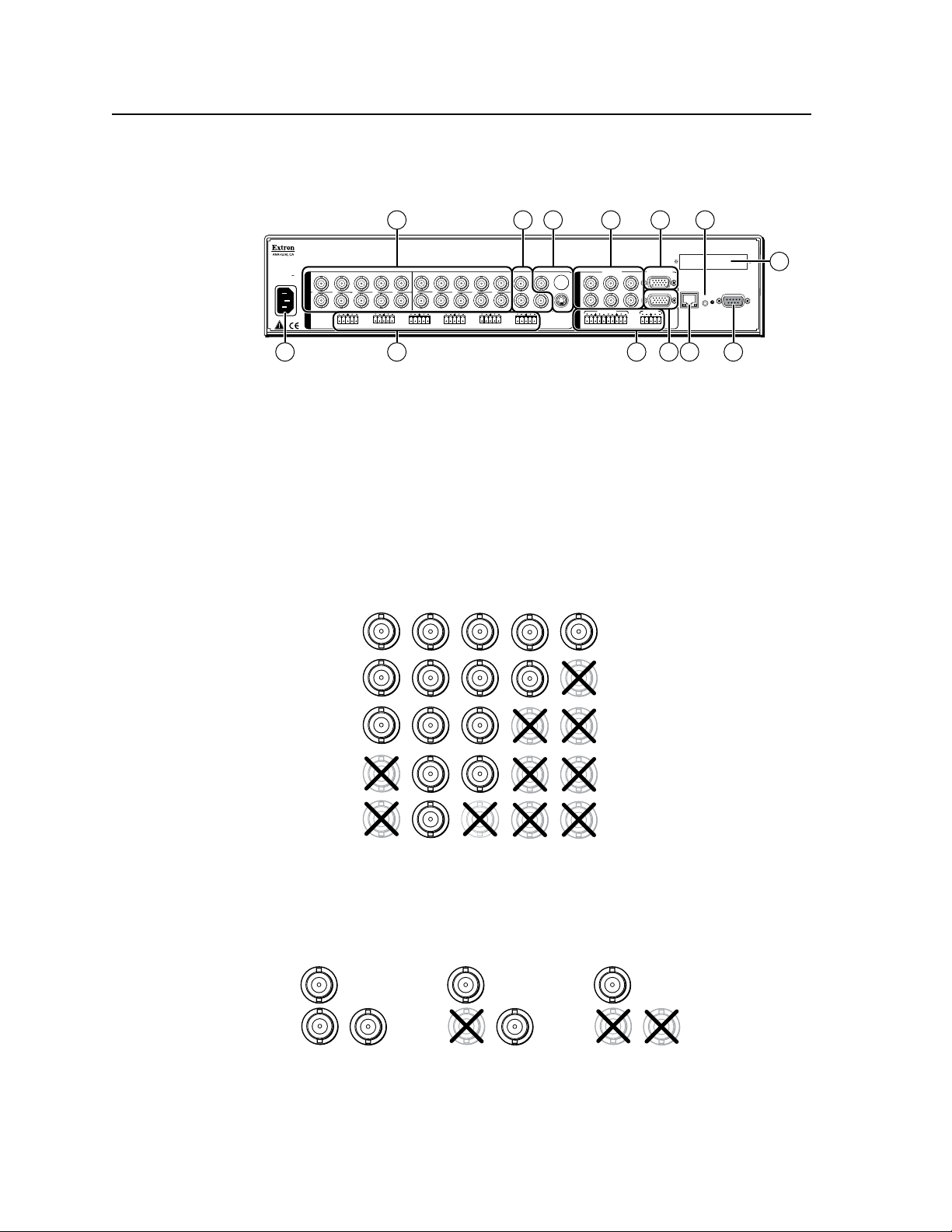
Cabling and Rear Panel Views
All connectors are on the rear panel (figure 2-2).
Figure 2-2 — ISS 506 rear panel connectors
Input connections
AC power connector — Plug a standard IEC power cord into this connector
a
to connect the seamless switcher to a 100 to 240 VAC, 50 Hz or 60 Hz power
source.
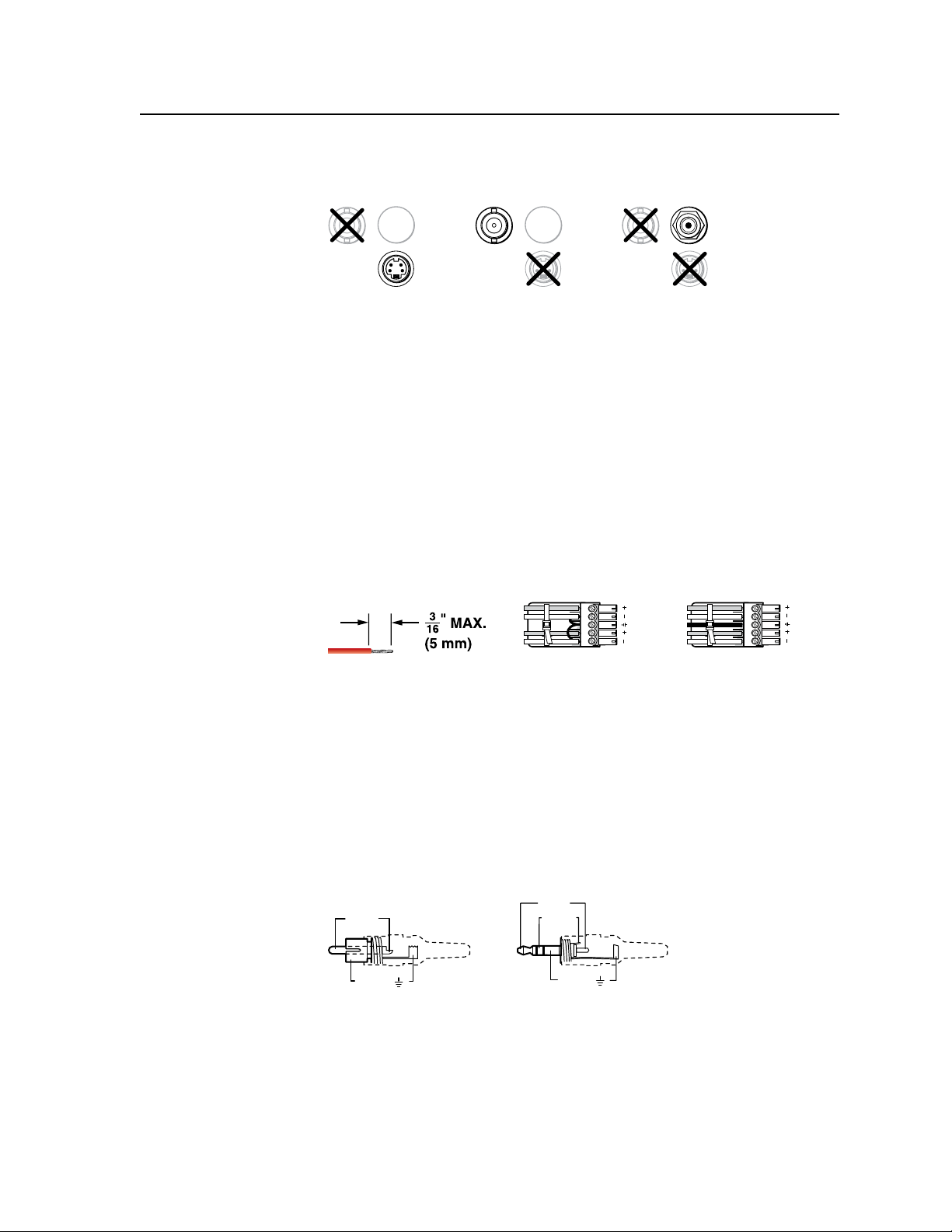
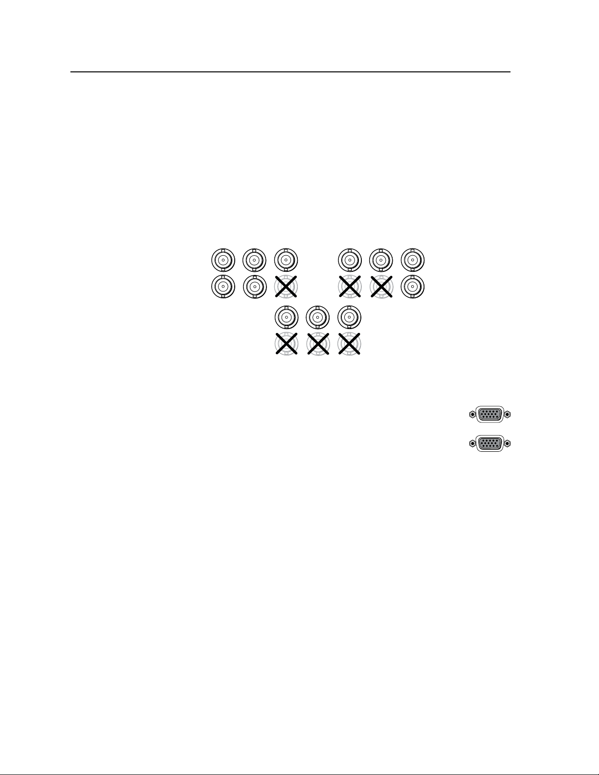
Video input connections
Input 1 through Input 4 video connectors — Connect computer or RGB
b
video, component video, S-video, or composite video sources to these female
BNC connectors. Figure 2-3 shows how to connect the various video formats.
Figure 2-3 — Connections for various input video formats
Input 5 video connectors — Connect a component video, S-video, or
c
composite video source to these female BNC connectors. Figure 2-4 shows
how to connect the various video formats.
2-4
ISS 506 Integration Seamless Switcher • Installation
Figure 2-4 — Connections for input 5 video formats
Page 21
VID
6
YC
SDI
VID
6
YC
VID
6
YC
SDI
Composite Video SDI or HD-SDI Video
(Optional SDI/HDSDI Input Board Only)
S-Video
SDI
L R
L R
Unbalanced Stereo Input
Balanced Stereo Input
(high impedance)
(high impedance)
Do not tin the wires!
Ring
Sleeve (s)
Tip
Sleeve
Tip
Sleeve
Tip
Tip
Ring
Tip (+)
Sleeve ( )
Sleeve ( )
Ring (-)
Tip (+)
RCA Connector
3.5 mm Stereo Plug Connector
(balanced)
Input 6 video connectors — Connect either an S-video, a composite video, or
d
an SDI/HD-SDI video source to these connectors (figure 2-5).
Figure 2-5 — Connections for input 6 video formats
N
The SDI/HD-SDI video input is available only on the ISS 506 DI/DVI, the
ISS 506 DI/SC, and the ISS 506 DI/HD-SDI.
N
Although all video formats can be physically connected, input 6 cannot accept
multiple video inputs simultaneously.
Audio input connections
Input audio connectors — Connect balanced or unbalanced stereo or mono
e
audio to these 3.5 mm, 5-pole captive screw connectors. Connectors are
included with the seamless switcher, but you must supply the audio cable.
Figure 2-6 shows how to wire a connector for the appropriate input type.
the supplied tie-wrap to strap the audio cable to the extended tail of the connector.
High impedance is generally over 800 ohms.
Figure 2-6 — Captive screw connector wiring for inputs
C
The length of the exposed (stripped) portion of the copper wires is
important. The ideal length is 3/16" (5 mm). Longer bare wires can
short together. Shorter bare wires are not secure enough in the direct
insertion connectors and could be pulled out.
N
When making connections for the seamless switcher from existing audio cables,
see figure 2-7. A mono audio connector consists of the tip and sleeve. A stereo
audio connector consists of the tip, ring, and sleeve. The tip, ring, and sleeve
wires are also shown on the captive screw audio connector diagram, figure 2-6.
Use
Figure 2-7 — Typical audio connectors
The audio level for each input can be individually set via the front panel, the
Ethernet link, or the RS-232/RS-422 link, to ensure that the level on the output
does not vary from input to input. See chapter 3, “Operation”, chapter 4,
“SIS Programming and Control”; and chapter 5, “Scaler Software”, for details.
ISS 506 Integration Seamless Switcher • Installation
2-5
Page 22
Installation, cont’d
RGBHV
Video
RGBS
Video
RGsB and
Component
Video
S
H
V
G
/Y
R
R-Y
B/
B-Y
S
H
V
G
/Y
R
R-Y
B/
B-Y
S
H
V
G
/Y
R
R-Y
B/
B-Y
Output connections
Video output connections
N
The Program connectors (
monitor or projector. The Preview connectors (h) output the video image for the
local monitor.
f
The two Program Video outputs, consisting of one set of five BNC connectors
and a 15-pin HD connector, output identical video signals at the same
resolution, refresh rate, and sync format.
and g) output the video image for the program
f
Program video output BNC connectors — Connect an RGB or component
video display to these female BNC connectors. Figure 2-8 shows how to
connect the various video formats.
Figure 2-8 — BNC output connections for RGBHV, RGBS, RGsB, and
component video
Program video output 15-pin HD connector — Connect an RGB
g
or component video display to this female 15-pin HD connector.
Preview video output 15-pin HD connector — Connect an RGB
h
or component video display to this female 15-pin HD connector.
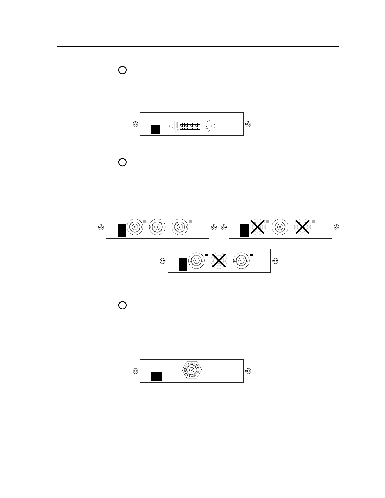
Optional video output connections
One of three possible output expansion boards can be installed in this location. The
expansion board receives the program output. The available output boards are:
• ADVIoutputboard
• Ascanconverter(lowresolution)outputboard
• AnHD-SDIoutputboard
2-6
ISS 506 Integration Seamless Switcher • Installation
Page 23
9a
DVI
OUT
9b
LORES
OUT
R-Y/
R
C
Y/
G
VID
B-Y/
B
Y
Component or RGsB Video
LORES
OUT
R-Y/
R
C
Y/
G
VID
B-Y/
B
Y
Composite Video
LORES
OUT
R-Y/
R
C
Y/
G
VID
B-Y/
B
Y
S-Video
9c
HDSDI
OUT
DVI output connector (optional) — If the optional DVI output board
(figure 2-9) is installed, connect a DVI/HDMI-compatible video display to
this DVI connector. This connector outputs the program image only. For
an HDMI-compatible display, connect the display through a DVI-to-HDMI
adapter, part #26-497-01 (DVI [male] to HDMI [female] adapter) or 26-498-01
(DVI [female] to HDMI [male] adapter).
Figure 2-9 — Optional DVI output board
Scan converter output connectors (optional) — If the optional scan converter
output board is installed, connect a low resolution video (RGsB video,
interlaced component video, S-video, or composite video) display to these
female BNC connectors. These connectors output the program image only.
Figure 2-10 shows how to connect the various video formats.
N
The scan converter board can output S-video and composite video
simultaneously.
Figure 2-10 — Optional scan converter output board
HD-SDI output connectors (optional) — If the optional HD-SDI output
board is installed, connect an HD-SDI display to this female BNC connector
(figure 2-11). This connector outputs the program image only.
N
You must set the scaler’s output rate to 720p (at 25, 30, 50, 59.94, or 60 Hz),
1080i (at 50, 59.94 or 60 Hz), or 1080p (at 24, 25, or 30 Hz) for the HD-SDI
board to produce an output. See “Resolution and refresh rate submenu“ in
chapter 3, “Operation”.
Figure 2-11 — Optional HD-SDI output board
ISS 506 Integration Seamless Switcher • Installation
2-7
Page 24
Installation, cont’d
Unbalanced Stereo Output Balanced Stereo Output
L R
Do not tin the wires!
Ring
Sleeve(s)
Tip
Tip
Ring
Sleeve(s)
Tip
Tip
NO GROUND HERE.
NO GROUND HERE.
Link
LED
Activity
LED
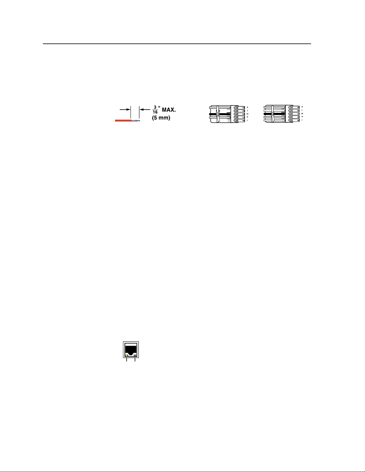
Audio output connections
Preview and Program audio output connectors — Connect audio devices,
j
such as an audio amplifier or powered speakers, to these 3.5 mm, 5-pole
captive screw connectors. The connectors output the selected unamplified,
line level audio. See figure 2-12 to properly wire an output connector.
supplied tie-wrap to strap the audio cable to the extended tail of the connector.
Figure 2-12 — Captive screw connector wiring for audio output
Use the
C
Connect the sleeve to ground (Gnd). Connecting the sleeve to a
negative (-) terminal will damage the audio output circuits.
C
The length of the exposed (stripped) portion of the copper wires is
important. The ideal length is 3/16" (5 mm). Longer bare wires can
short together. Shorter bare wires are not secure enough in the direct
insertion connectors and could be pulled out.
N
The level of the audio output on the Variable Program output connector can be
adjusted using the front panel Volume control.
The Preview Output and the Fixed Program output connectors are not affected
by the front panel Volume control.
By default, the audio output follows the video switch. Audio breakaway,
commanded via the Ethernet link or the RS-232/RS-422 link, allows you
to select from any one of the audio input sources. See chapter 4, “SIS
Programming and Control”; chapter 5, “Scaler Software”; and chapter 6,
“Ethernet Operation”, for details.
Control connections
Ethernet connection
LAN port — If desired, connect the seamless switcher to an Ethernet LAN or
k
WAN via this RJ-45 connector. Ethernet control allows the operator to control
the seamless switcher from a remote location. When connected to an Ethernet
LAN or WAN, the seamless switcher can be accessed and operated from a
computer running a standard Internet browser.
2-8
Ethernet connection indicators — The Link and Activity LEDs indicate the
status of the Ethernet connection.
The Link LED indicates that the seamless switcher is properly
connected to an Ethernet LAN. This LED should light steadily.
The Activity LED indicates transmission of data packets on the
RJ-45 connector. This LED should flicker as the seamless switcher
communicates.
Cabling and RJ-45 connector wiring
It is vital that your Ethernet cables be the correct cables, and properly terminated
with the correct pinout.
ISS 506 Integration Seamless Switcher • Installation
Page 25
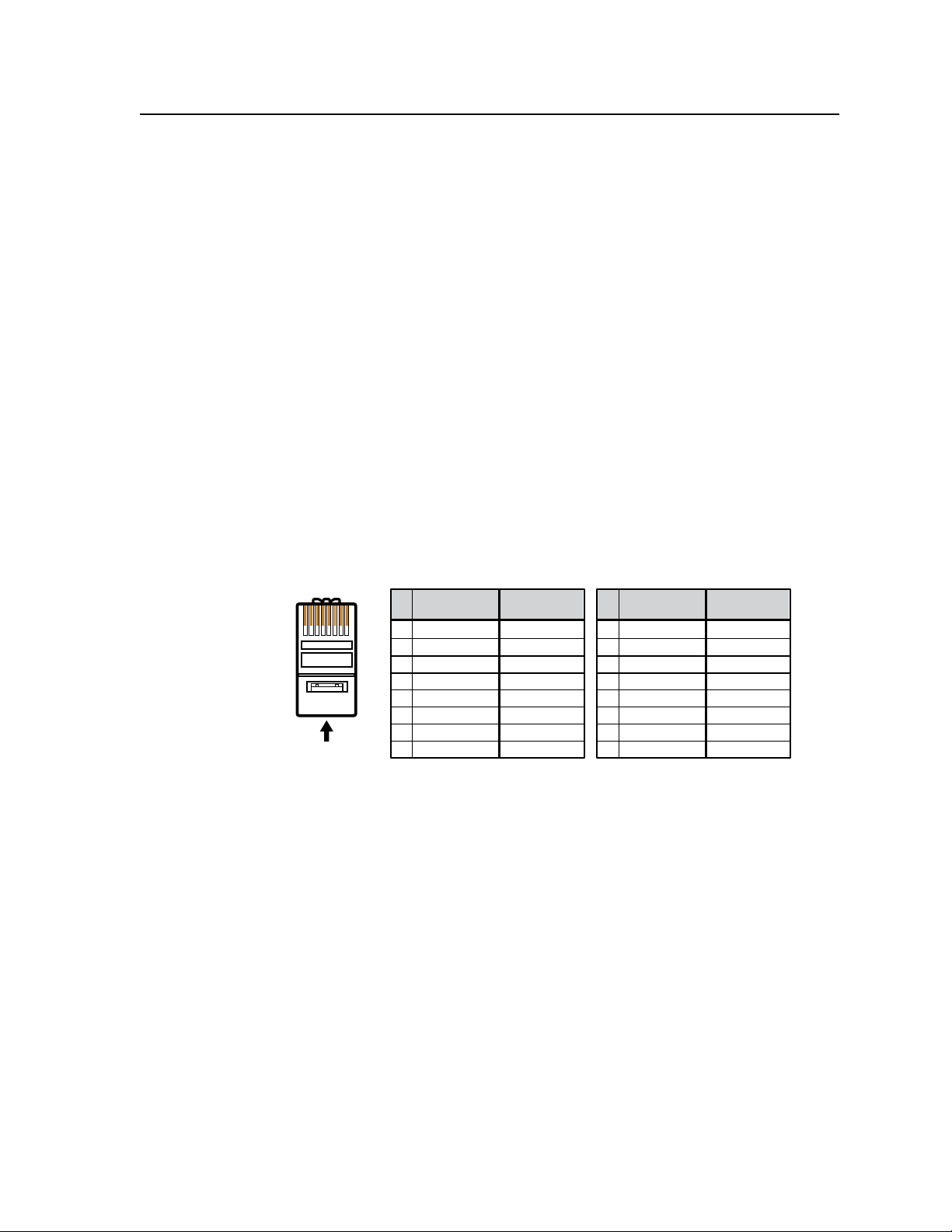
A cable that is wired as T568A at one end
and T568B at the other (Tx and Rx pairs
reversed) is a "crossover" cable.
A cable wired the same at both ends is
called a "straight-through" cable, because
no pin/pair assignments are swapped.
12345678
RJ-45
Connector
Insert Twisted
Pair Wires
Pins:
Crossover Cable Straight-through Cable
Pin
1
2
3
4
5
6
7
8
Wire color
White-green
Green
White-orange
Blue
White-blue
Orange
White-brown
Brown
Wire color
T568A T568B
End 1 End 2 End 1 End 2
White-orange
Orange
White-green
Blue
White-blue
Green
White-brown
Brown
Pin
1
2
3
4
5
6
7
8
Wire color
White-orange
White-green
Blue
White-blue
White-brown
Brown
Wire color
T568BT568B
White-orange
OrangeOrange
White-green
Blue
White-blue
GreenGreen
White-brown
Brown
Choosing a network cable
Ethernet links use Category (CAT) 3, 4, 5, 5e, or 6, unshielded twisted pair (UTP)
or shielded twisted pair (STP) cables, terminated with RJ-45 connectors. Ethernet
cables are limited to 328' (100 m).
N
Do not use standard telephone cables. Telephone cables do not support Ethernet
or Fast Ethernet.
N
Do not stretch or bend cables. Transmission errors can occur.
The cable used depends on your network speed. The ISS supports both 10 Mbps
(10Base-T — Ethernet) and 100 Mbps (100Base-T — Fast Ethernet), half-duplex and
full-duplex Ethernet connections.
• 10Base-TEthernetrequiresataminimumCAT3UTPorSTPcable.
• 100Base-TFastEthernetrequiresataminimumCAT5UTPorSTPcable.
Wiring the network cable
The cable can be terminated as either a patch cable or a crossover cable (figure 2-13)
and must be properly terminated for your application:
• Patch (straight) cable — Connection of the ISS to an Ethernet hub, router, or
switch that also hosts a controlling computer
• Crossover cable — Direct connection between the ISS and a controlling
computer
Figure 2-13 — RJ-45 connector pinout table
ISS 506 Integration Seamless Switcher • Installation
2-9
Page 26

Installation, cont’d
RS-232 Function Pin Function
1
2
3
4
5
6
7
8
9
—
TX
RX
—
Gnd
—
—
—
—
Not used
Transmit data
Receive data
Not used
Signal ground
Not used
Not used
Not used
Not used
—
TX–
RX–
—
Gnd
—
RX+
TX+
—
Not used
Transmit data (–)
Receive data (–)
Not used
Signal ground
Not used
Receive data (+)
Transmit data (+)
Not used
RS-422
RS232/422
RESET
LAN
Serial port connection
RS-232/422 port — Connect a host device, such as a computer or touch
l
panel control, to the ISS 506 Integration Seamless Switcher via this 9-pin D
connector for serial RS-232 or RS-422 control (figure 2-14).
Figure 2-14 — Remote port pin assignments
See chapter 4, “SIS Programming and Control”, for definitions of the SIS
commands and chapter 5, “Scaler Software”, to install and use the control
software.
Reset button
Reset button — The Reset button initiates four levels of reset
m
to the matrix switcher. Use and Extron Tweeker or small
screwdriver to press and hold the button while the switcher is
running or while you power up the switcher, for different reset
levels.
See “Rear Panel Reset Button” in chapter 3, “Operation”, for details.
• Events (mode 3) reset — Hold Reset for 3 seconds, then release it and
push it again to toggle events monitoring on and off.
• IP settings (mode 4) reset — Hold Reset for 6 seconds, then release it and
push it again to reset the switcher’s IP functions.
N
IP settings reset does not replace any user-installed firmware.
• Absolute (mode 5) reset — Hold Reset for 9 seconds, then release it and
push it again to restore the switcher to the default factory conditions
(without resetting the firmware).
• Hard reset — Hold Reset while powering up the switcher to revert to
the factory default firmware (in the event that firmware incompatibility
issues occur).
2-10
ISS 506 Integration Seamless Switcher • Installation
Page 27
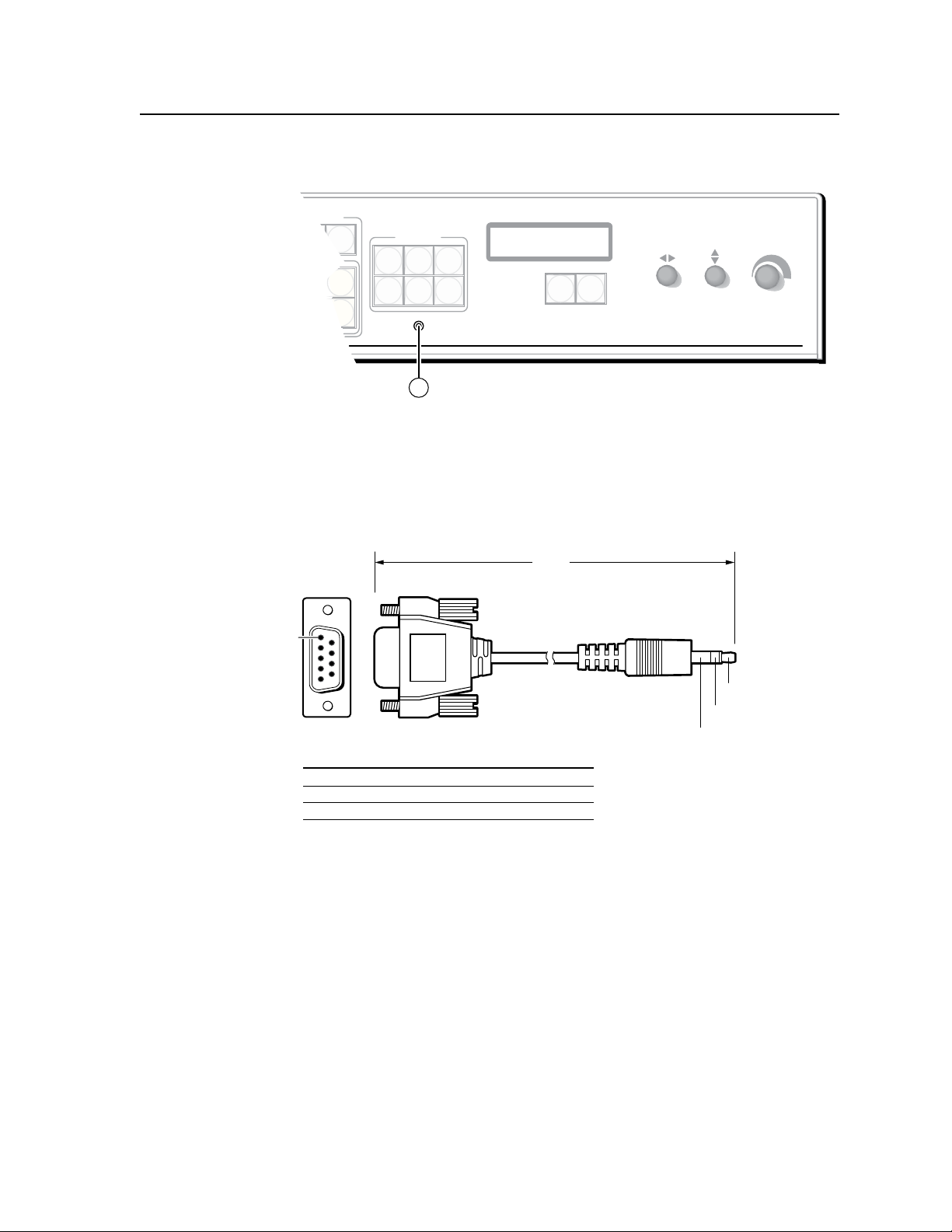
TRANSITION
PICTURE
ADJUSTMENTS
CONFIG
ZOOM
TAKE
PIP
TITLE
SIZE DETAIL
POSITION
BRIGHT/
CONT
COLOR/
TINT
ISS 506
Integration Seamless Switcher
VOLUME
ADJUST
ADJUST
MENU
NEXT
14
6 feet
(1.8 m)
Part #70-335-01
5
1
9
6
Sleeve (Gnd)
Ring
Tip
9-pin D Connection TRS Plug
Pin 2 Computer's RX line Tip
Pin 3 Computer's TX line Ring
Pin 5 Computer's signal ground Sleeve
Front Panel Configuration Port
Figure 2-15 — Front panel configuration port
Configuration port — This 2.5 mm mini stereo jack serves the same serial
n
communications function as the rear panel Remote port, but it is easier
to access than the rear port after the matrix switcher has been installed
and cabled. The optional 9-pin D to 2.5 mm mini jack TRS RS-232 cable,
part #70-335-01 (figure 2-16), can be used for this connection.
Figure 2-16 — Optional 9-pin TRS RS-232 cable
N
This port is independent of the rear panel RS-232/RS-422 port. A front panel
Configuration port connection and a rear panel RS-232/RS-422 port connection
can both be active at the same time.
This port is RS-232 only, with its default protocols as follows:
• 9600baud • noparity • 8databits
• 1stopbit • noowcontrol
N
The maximum distance from the seamless switcher to the controlling device
can vary up to 200 feet (61 m). Factors such as cable gauge, baud rates,
environment, and output levels (from the switcher and the controlling device)
all affect transmission distance. Distances of about 50 feet (15 m) are typically
not a problem. In some cases the matrix switcher may be capable of serial
communications via RS-232 up to 250 feet (76 m) away.
ISS 506 Integration Seamless Switcher • Installation
2-11
Page 28

Installation, cont’d
Configuration
The ISS can be configured using either the front panel controls, the SIS, the HTML
pages, or the Windows-based Control program. See chapter 3, “Operation”;
chapter 4, “SIS Programming and Control”; chapter 5, “Scaler Software”, and
chapter 6, “HTML Operation”.
2-12
ISS 506 Integration Seamless Switcher • Installation
Page 29

ISS 506 Integration Seamless Switcher
Chapter Three
3
Operation
Front Panel Controls and Indicators
Front Panel Operations
Rear Panel Reset Button
Optimizing the Video
Optimizing the Audio
Troubleshooting
Page 30
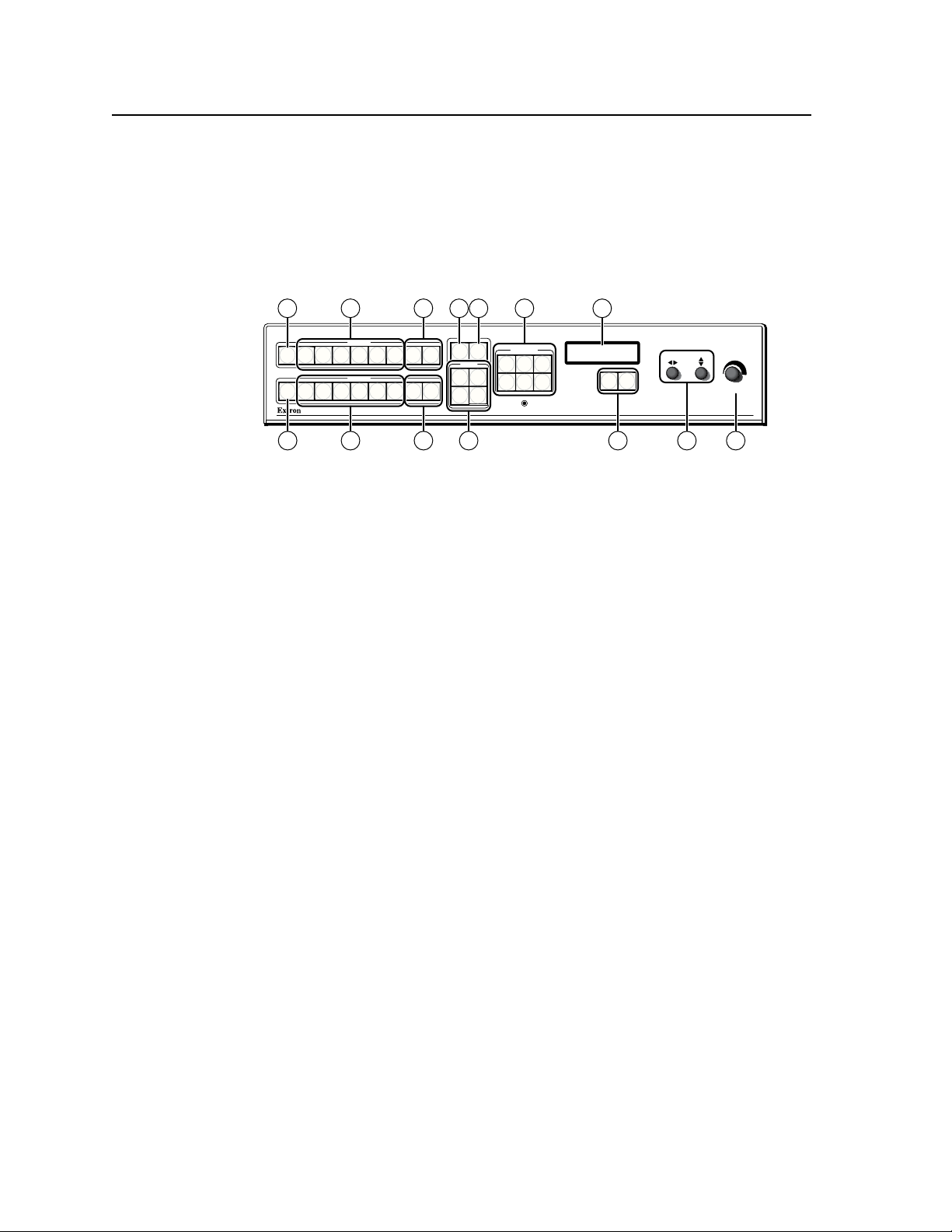
Operation
ISS 506
Integration Seamless Switcher
VOLUME
ADJUST
ADJUST
TRANSITION
PICTURE
ADJUSTMENTS
CONFIG
PROGRAM
PREVIEW
EFFECTS
MENU
NEXT
DETAIL
ZOOM
BRIGHT/
CONT
COLOR/
TINT
SIZE
POSITION
TAKE
CUT
PIP
TITLE
WIPE
DISSOLVE
LOGO 2
/BLACK
LOGO 1
/BLACK
1 2
3
4
5
6
1
2
3
4
5
6
LOGO 2
/BLACK
LOGO 1
/BLACK
FREEZE
FREEZE
1
1 4 85
11
2
2
3
3 96
7
10
Front Panel Controls and Indicators
Freeze, input selection, Logo/Black, and Cut/Dissolve controls
All of the switcher’s controls and indicators, with the exception of the Reset
button, are on the front panel (figure 3-1). The buttons can be set to provide amber
background illumination all the time or the background illumination can be turned
off (see “Toggling background illumination on and off”, on page 3-37. The program
and preview input selection buttons can be labeled with text and/or graphics. The
16 x 2 LCD window indicates the switcher status, menu selections, the data rate,
and the status of additional system features.
Figure 3-1 — ISS 506 front panel
Freeze buttons — The two Freeze buttons lock the program output or
a
preview output display to the currently selected input image. When the
freeze function is enabled, these buttons light green. Press the Freeze button
again to unfreeze the image.
N
The freeze function has no effect on the audio output.
3-2
ISS 506 Integration Seamless Switcher • Operation
Input selection buttons — The two sets of Input 1 through 6 buttons select
b
the associated input to scale and display on the program and preview
monitors. The input buttons light amber when video and audio are selected.
N
Input selections can be made with audio broken away under RS-232/RS-422 or
Ethernet control only. See chapter 4, “SIS Programming and Control“; chapter
5, “Switcher Software“; and chapter 6, “HTML Operation“.
N
The input button lights green when video only is selected.
The input button lights red when audio only is selected.
Video and audio outputs can be muted under RS-232/RS-422 or Ethernet
control only. See chapter 4, “SIS Programming and Control“; chapter 5,
“Switcher Software”; and chapter 6, “HTML Operation“.
The Input button blinks, alternating between red and amber when video is
muted.
The input button blinks, alternating between green and amber when audio is
muted.
c
The input button blinks amber when both video and audio are muted.
Logo/Black buttons — The four Logo/Black buttons (two buttons, Logo 1
and Logo 2, for both the program output and the preview output) switch the
program output or preview output to a black screen or superimpose one of
two stored logos on top of the selected input.
Cut button — Pressing the Cut button causes the ISS to immediately switch
d
the input selected as the preview output to the program output, with no
switching effects added. The Cut button flashes when selected to indicate the
switch taking place.
Page 31

Take button — Pressing the Take button causes the ISS to switch the input
e
that was selected as the preview output with the program output, using the
effect that was selected by the lit Effect button (
The Take button blinks for the duration of the switching effect. For the PIP
and Title effect, Take blinks as long as the PIP window or title is displayed on
top of the program output
N
f
Take blinks when the PIP window or title is displayed on the program output
even if the effect was commanded using the Cut button.
Effects buttons — Press one of these Effects buttons - Wipe, Dissolve, PIP,
or Title, to select that effect to use when you press the Take button (
“Effects configuration menu”, later in this chapter, for more details.
Picture adjustment and menu system controls
Picture Adjustment buttons — The picture adjustment buttons select
g
individual image adjustments for the preview output or program output.
Pushing a button toggles between the preview and program outputs. The
selected picture adjustment is made using the Adjust [ and Adjust { knobs
).
(
j
N
N
If the PIP mode is selected, the preview output is shown and adjusted in the
picture-in-picture window and the program output is shown and adjusted in the
main (full-size) window.
For more information on these buttons and adjustments, see “Adjusting the
picture”, later in this chapter..
f
).
). See
e
Size control button — The Size button selects the display size adjustment.
The adjustment range depends on the output resolution that was selected.
Brightness/Contrast control button — The Brightness/Contrast button selects
the display brightness and contrast adjustments. The adjustment range for
both brightness and contrast is from 0 to 127.
Filter control (Detail) button — The Detail button selects the display image
detail (sharpness) adjustment. The sharpness adjustment compensates for
long cable runs. The adjustment range for the filter is from 0 to 127.
Position control button — The Position button selects the display centering
adjustment. The adjustment range depends on the output resolution that was
selected.
Color/Tint control button — The Color/Tint button selects the display color
and tint adjustments. The adjustment range for both color and tint is from 0
to 127.
N
Color adjustments are available only for component video, S-video, and
composite video inputs.
Tint adjustments are available only for S-video and composite NTSC video
inputs.
Zoom button — The Zoom button selects the zoom adjustments (allowing
you to make the image or the window larger).
ISS 506 Integration Seamless Switcher • Operation
3-3
Page 32

Operation, cont’d
Status display — The 16-column by 2-line LCD window displays
h
configuration menus and status information. See “Menu system overview”,
below, and “Front Panel Operations”, later in this chapter, for details.
Menu button — The Menu button enters and moves through the main menu
i
system in the ISS. See “Menu system overview”, below, and “Front Panel
Operations”, later in this chapter, for details.
Next button — The Next button steps through the submenus in the ISS menu
system. See “Menu system overview”, below, and “Front Panel Operations”,
later in this chapter, for details.
Adjust [ (horizontal) and Adjust { (vertical) knobs — The Adjust [ and
j
Adjust { knobs change settings when used in conjunction with the menu
system or the picture adjustment buttons.
Volume knob — The Volume knob changes the attenuation of the audio
k
output on the Program Variable audio output.
N
Menu system overview
Figure 3-2 shows a flowchart of the main menus in the menu system.
The Preview Output and the Fixed Program audio output connectors are not
affected by the front panel Volume control.
N
Menu button — Press the Menu button to activate the menu system and to scroll
Next button — Press the Next button to move between the submenus of a selected
Adjust [ and Adjust { knobs — When a submenu is active, rotate the Adjust [
When one of the picture adjustment buttons is selected, rotate these knobs to
Refer to the flowcharts in this chapter and to specific sections for explanations
N
N
N
On figure 3-2 and all other flowcharts in this chapter, solid lines indicate screen
changes initiated by the operator. Dashed lines indicate screen changes that are
the result of a timeout function.
through the nine or ten main menus.
main menu, to activate a submenu for viewing or configuration, and to save
a selection. Pressing the Next button during input configuration causes the
current input’s number and format type to be displayed on the LCD window.
knob and Adjust { knob to scroll through the submenu options and select a
setting.
change picture settings.
of the knob adjustments.
If you press the Menu button while a main menu is active, the next main menu
becomes active.
If you press the Menu button while a submenu is active, the LCD window backs
up to display that submenu’s main menu.
To return to the default screens, let the switcher remain idle for 30 seconds until
the selected screen times out; or press the Menu button until the Exit Menu
appears, then press the Next button.
From any menu or submenu, after 30 seconds of inactivity, the ISS saves all
adjustment settings and times out to the default LCD display cycle.
3-4
ISS 506 Integration Seamless Switcher • Operation
Page 33

Default
Cycle
Menu
2 sec.
Power
on
Menu
Next
Menu
Menu
Menu
* This menu is availab le only
if the optional scan converter
board is installed.
Menu
Menu
Menu
30 sec.
30 sec.
30 sec.
Input
Configuration
Output
Configuration
Auto
Image
Integration
SeamlessSwitcher
Menu Menu
30 sec. 30 sec. 30 sec.
View Comm
Settings
Scan Conver ter
Configuration
Advanced
Configuration
Exit Menu
Press Next
Menu Menu
30 sec. 30 sec.
Logo
Capture
User
Presets
Effects
Configuration
Menu Menu
30 sec. 30 sec.
*
2 sec.
Extron
ISS 506 Vn.nn
10 sec.
Initializing
Please Wait...
Figure 3-2 — Menu system flowchart
ISS 506 Integration Seamless Switcher • Operation
3-5
Page 34

Operation, cont’d
• Program • Preview
• Both
Default
Cycle
Menu
Menu
30 sec. 30 sec.
Menu
Menu
Next
Next Next
Menu
Menu
Menu
Menu
Menu
Menu
Menu
Menu
Auto
Image
Input
Configuration
Output
Configuration
Effects
Configuration
Logo
Capture
User
Presets
Advanced
Configuration
View Comm
Settings
Scan Converter
Configuration
Exit Menu
Press Next
Select Output
Program
*
* This menu is available
only if the optional
scan converter board
is installed.
Auto Image menu
Figure 3-3 shows an overview of the Auto Image menu, the Select output submenu,
and the available settings.
3-6
Figure 3-3 — Auto Image menu flowchart
Select Output submenu
The auto imaging feature automatically sizes and centers the selected input to fill
the screen. Command the auto imaging adjustment for a specific input by rotating
either Adjust knob to select either the program output, preview output, or both
outputs, and pressing the Next button to apply the auto image correction.
Alternatively, using the menu system, you can set this feature to apply the Auto
Image adjustments to every input as it is selected (see “Auto Image submenu” on
page 3-20).
Input Configuration menu
Figure 3-4, on the next page, shows an overview of the Input Configuration menu
and the available settings.
ISS 506 Integration Seamless Switcher • Operation
Page 35

Default
Cycle
Menu
Menu
Menu
Menu
Next
Menu
Menu
Menu
Menu
Menu
Menu
Menu
Input
Configuration
Auto
Image
Output
Configuration
Effects
Configuration
Logo
Capture
User
Presets
Advanced
Configuration
View Comm
Settings
Scan Converter
Configuration
Exit Menu
Press Next
*
30 sec.30 sec. 30 sec. 30 sec.
30 sec.
30 sec. 30 sec.
30 sec.
Input #1
through
input #6
Input #1
through
input #6
Next
RGB
1-4
, YUV-HD
1-4
,
YUVp
1-4
, RGBcvS
1-4
,
YUVi
1-5
, S-Video
1-6
,
Composite
1-6
,
Auto YUV
1-4
, SDI6,
HDSDI
6,
Auto SDI
6
NOTE The small numbers after each listed video format (such as
RGB
1-4
) indicate the input(s) for which this video format is valid.
-18 dB to
+24 dB
Next
Input #1
through
input #6
Off or On
Next
Input #1
through
input #6
Variable
depends on
the input.
Variable
depends on
the input.
Input #1
through
input #6
00
through
31
Next Next
Input #1
through
input #6
Input #1
through
input #6
Input #1
through
input #6
Input #1
through
input #6
00
through
31
Next
Input #1
through
input #6
Next
30 sec. 30 sec. 30 sec.
Next Ne xt
Next
Nex
t
Menu
Input #1
RGB
Input #1
V Start:0000
Input #1
H Start:0000
Input #1
Preview Phase:0000
Input #1
Program Phase:0000
Audio #1 Level
0 dB
Input #1
Film Mode Off
Input #1
Tot. Pixels:1344
Input #1
Act. Pixels:1024
Input #1
Act. Lines:0768
* This menu is available
only if the optional
scan converter board
is installed.
Total pixels
depend on
the input.
Active pixels
depend on
the input.
Active lines
depend on
the input.
Figure 3-4 — Input Configuration menu flowchart
Input format submenu
Rotate the Adjust [ knob while the Input format submenu is active to select
an input to configure. Rotate the Adjust { knob to select the correct video
format (RGB, HDTV component video, progressive component video [YUVp],
RGBcvS, low resolution component video [YUVi], S-video, composite video, or
SDI/HD-SDI) for the selected input.
N
The RGB, HDTV and progressive component video, and RGcvS formats are
displayed for inputs 1 through 4 only.
The low resolution component video format is displayed for inputs 1 through 5 only.
The S-video and composite video formats are displayed for all inputs.
The SDI video input and HD-SDI video input are displayed for input 6 only,
and only if the optional SDI input board is installed.
The Auto YUV selection detects between YUVi, YUVp, and YUV-HD as the
input format.
The Auto SDI selection measures the input frequency and automatically sets the
scaler to either SDI or HD-SDI.
ISS 506 Integration Seamless Switcher • Operation
3-7
Page 36

Operation, cont’d
Vertical
Start
Horizontal
Start
Active Area
Active Blanking Area
Audio Level submenu
Rotate the Adjust [ knob while the Input format submenu is active to select an
input to configure. Rotate the Adjust { knob to select the audio gain or attenuation
value, from -18 dB to +24 dB. The default for each input is a 0 dB audio level.
Film Mode submenu
The Film Mode submenu lets you turn PAL film mode (2:2 pulldown detection) on
and off for each input. The PAL film mode should be used for a PAL video source
that originated from film. PAL film mode applies video processing algorithms that
optimize the conversion of video that was made with the 2:2 pulldown (PAL video
from film) process.
Rotate the Adjust [ knob while the Input format submenu is active to select an
input to configure. Rotate the Adjust { knob to select On or Off.
Vertical Start and Horizontal Start submenus
The Vertical Start submenu defines the number of lines per frame that are inside
the blanking area above the active area (figure 3-5). The Horizontal Start submenu
defines the number of pixels per line that are inside the blanking area to the left of
the active area.
3-8
ISS 506 Integration Seamless Switcher • Operation
Figure 3-5 — Incorrectly started image
Both submenus adjust where the electronic scaling process takes effect. The input
starting point and active area should be manually adjusted, if necessary, to match
the input video signal, framing the active area of the input signal. If the start point
is set incorrectly, the scaler may add blank borders on the leading edges (top or left
side) or it may crop the active area on the trailing edges (bottom or right side).
Select the appropriate submenu. Rotate the Adjust [ knob while the Input format
submenu is active to select an input to configure. Rotate the Adjust { knob to set
the start variable.
N
Figure 3-5 shows an image that is improperly started (as indicated by the dashed
lines). If the horizontal start adjustment is set to less than the amount of actual
blanking, the ISS starts scaling the input before the start of the active image.
Page 37

Total Pixels
Active
Area
Blanking Area
This early scaling results in a blank border on the left side and cropping on the
right side, and looks as if the image is shifted to the right.
Preview and Program Phase submenus
The Preview and Program Phase submenus display and let you set the pixel phase,
which is the timing of the digital scaler’s sampling. Sampling at the optimum pixel
phase results in a brighter scaled output.
Select the desired submenu. Rotate the Adjust [ knob while the Input format
submenu is active to select an input to configure. Rotate the Adjust { knob to set
the phase variable from 0 to 31. The default is 16.
Similarly, if the vertical start adjustment is set to less than the amount of actual
blanking, the ISS starts scaling before the first line of the active image. This
early scaling results in a blank border on the top and cropping on the bottom,
and looks as if the image is shifted down.
Adjust the Vertical Start variable to shift the starting period vertically on the
screen. Adjust the Horizontal Start variable to shift the scaler’s starting point
horizontally on the screen.
If improperly adjusted, the output position variable can result in an image
similar to figure 3-5. The position adjustment only moves the image on the
monitor. It does not add blank borders or crop any part of the image. However,
the apparent effect of blank borders and a cropped image can be caused by the
image being improperly positioned on the monitor.
Total Pixels submenu
The total pixels variable (RGB and progressive/HDTV component only) defines the
total number of pixels per line, including the blanking on both sides of the input
active area (active, horizontal sync width, back porch, and front porch).
There are several methods to determine the correct value to use in the total pixels
variable. Usually, the best method is to use the input signal specifications. For
some input sampling rates, the scaler’s setting can result in fine vertical lines
(figure 3-6).
Figure 3-6 — Incorrect total pixels variable
ISS 506 Integration Seamless Switcher • Operation
3-9
Page 38

Operation, cont’d
Active Pixels
Active
Lines
Incorrect Active Area
Active Area
Blanking Area
These lines appear as fuzzy vertical bars when an alternating pixels pattern is
applied. When the total pixels setting is improperly adjusted, the entire image can
have a noisy or darkened appearance. Adjusting the phase corrects this.
As an approximate setting, multiply the active pixels setting (see “Active Pixels and
Active Lines submenus”, below) by a factor of 1.3.
If the input pixel clock rate is known, the input total pixels setting can be calculated
with this equation: total pixels = input pixels clock ÷ input horizontal scan rate.
Once a preliminary setting is saved, some faint vertical lines may remain. Adjust
the total pixels variable as necessary until the lines are completely out of view or
as far apart as you can make them. If one line remains, it can be moved out of
view using the Phase submenu (see “Preview and Program Phase submenus” on
page 3-9).
N
The active pixels and total pixels adjustments are interactive. Setting one of
these variables may require adjusting the other.
Active Pixels and Active Lines submenus
Two submenus define the active (image) area of the input (figure 3-7):
• Active pixels — The number of pixels per line that are inside the input active
area. The baseline for the active pixels adjustment is the right edge of the
image. This value is often referred to as “horizontal resolution”.
• Active lines — The number of lines per frame that are inside the input active
area. The baseline for the active lines adjustment is the bottom edge of the
image. This value is often referred to as “vertical resolution”.
For interlaced input signals, this variable refers to the total number of lines
per frame after de-interlacing, not the number of lines per field.
3-10
Figure 3-7 — Incorrect active area setting
Select the desired submenu. Rotate the Adjust [ knob while the Input format
submenu is active to select an input to configure. Rotate the Adjust { knob to set
the Active Pixels or Active Lines variable.
ISS 506 Integration Seamless Switcher • Operation
Page 39

Polarity combinations
• H-/V- (default)
• H-/V+
• H+/V-
• H+/V+
30 sec.
30 sec. 30 sec.
Next
Next Next
Next
30 sec.
Output resolutions
See the table on the
next page for available
combinations of
resolutions and
refresh rates.
Default: 1024x768
Output frequencies
Default: 60 Hz
Output signal format
• RGBHV
• RGsB
• YUV bi-level
• YUV tri-level
Menu
* This menu is available
only if the optional
scan converter board
is installed.
� This submenu is
available only if the
output type format
(previous submenu)
is RGBHV.
Default
Cycle
Menu
Menu
Menu
Menu
Next
Menu
Menu
Menu
Menu
Menu
Menu
Menu
Output
Configuration
Input
Configuration
Auto
Image
Effects
Configuration
Logo
Capture
User
Presets
Advanced
Configuration
View Comm
Settings
Scan Converter
Configuration
Exit Menu
Press Next
*
Res 1024 x 768
Refresh 60 Hz
Output Type
RGBHV
�
Sync Polarity
H- V-
Adjust the Active Pixels variable to increase and decrease the number of active
pixels, shifting the starting period horizontally on the screen. Adjust the Active
Lines variable to increase and decrease the number of lines.
N
Figure 3-7 shows an image whose active area is improperly set, as indicated by
the dashed lines. If the number of active image pixels that the scaler is set to
scale is less than the amount of actual active pixels that are input, the ISS scales
only the set active area and skips some of the input pixels. This early end to the
scaling process results in an output with fewer pixels than it should, and looks
as if the image is stretched horizontally.
Similarly, if the number of active image lines that the ISS is set to scale is less
than the amount of actual active lines that are input, the ISS scales only the
set active area and skips some of the input lines. This early end to the scaling
process results in an output that has fewer lines than it should, and looks as if
the image is stretched vertically.
Output Configuration menu
Figure 3-8 is a flowchart that shows an overview of the Output Configuration
menu, the submenus, and the available settings.
Figure 3-8 — Output Configuration menu flowchart
ISS 506 Integration Seamless Switcher • Operation
3-11
Page 40

Operation, cont’d
Resolution and refresh rate submenu
Rotate the Adjust [ knob while this submenu is active to select one of the available
output resolutions. See the table below.
Rotate the Adjust { knob while this submenu is active to select one of the available
refresh (vertical scanning) rates. See the table below.
Resolution 24 25 30 50 59.94 60 72 96 100 120
640 x 480 • • • • • •
800 x 600 • • • • • •
852 x 480 • • • • •
1024 x 768 • • • •
1024 x 852 • • • •
1024 x 1024 • • •
1280 x 768 • • • •
1280 x 1024 • • •
1360 x 765 • • •
1365 x 768 • • •
1366 x 768 • • •
1365 x 1024 • •
1400 x 1050 • •
1600 x 1200 • •
480p • •
576p • •
720p • • • • •
1080i • • •
1080p • • • • • •
1864 x 1050 • •
1280 x 800 • • •
1440 x 900 • • •
1680 x 1050 • •
1080p Sharp •
1920 x 1200* •
* 1920 x 1200 is available only in units that shipped after the first quarter of 2009.
Frequency (Hz)
3-12
The default resolution and rate is 1024 x 768 @ 60 Hz.
N
1080p Sharp is an HDTV 1080p rate specifically tailored to Sharp® Professional
displays (such as the G655u).
Changing the output resolution sets any assigned logos to black.
User presets are associated with an output resolution. Once you change the
output resolution, the previously saved presets have no effect.
ISS 506 Integration Seamless Switcher • Operation
Page 41

000 to 255
0.0 to 5.0 seconds
in 0.1 second
increments
0.0 to 5.0 seconds in
0.1 second increments
30 sec. 30 sec.
30 sec.
30 sec.
30 sec.
Next
*
Subeffect type
• S Right • S Cur tain In
• S Left • S Curtain out
• S Up • S Square in
• S Down • S Square out
• S Center in • S Plus in
• S Center out • S Plus out
• H Right • H Curtain In
• H Left • H Curtain out
• H Up • H Square in
• H Down • H Square out
• H Center in • H Plus in
• H Center out • H Plus out
• H Right • H Curtain In
• H Left • H Curtain out
• H Up • H Square in
• H Down • H Square out
• H Center in • H Plus in
• H Center out • H Plus out
Subeffect type
• Cut • Dissolve
• S Right • S Cur tain In
• S Left • S Curtain out
• S Up • S Square in
• S Down • S Square out
• S Center in • S Plus in
• S Center out • S Plus out
Next
Next
Next
30 sec. 30 sec.
Next
Next
Next
Menu
Default
Cycle
Menu
Menu
Menu
Menu
Next
Menu
Menu
Menu
Menu
Menu
Menu
Menu
Effects
Configuration
Input
Configuration
Auto
Image
Output
Configuration
Logo
Capture
User
Presets
Advanced
Configuration
View Comm
Settings
Scan Converter
Configuration
Exit Menu
Press Next
Dissolve Config
0.5 Seconds
0.0 to 5.0 seconds in
0.1 second increments
Wipe Config
S Right 0.5
Title config
Level 127
PIP Config
S Right 0.5
Border color
• None • Blue • Cyan
• Red • White • Yellow
• Green • Magenta • Black
PIP Border Color
None
PIP Audio
<
Main> PIP
*
* This menu is available
only if the optional
scan converter board
is installed.
Output Type submenu
Rotate either Adjust knob while this submenu is active to select the output video
type (RGBHV, RGsB, component [YUV] with tri-level sync, or component [YUV]
with bi-level sync).
Sync Polarity submenu
The display or projector may require a particular combination of horizontal (H) and
vertical (V) sync signal polarities. Select the appropriate combination of positive or
negative H and V sync by rotating either Adjust knob.
Effects Configuration menu
Figure 3-9 is a flowchart that shows an overview of the Effects Configuration menu,
the submenus, and the available settings.
Figure 3-9 — Effects Configuration menu flowchart
ISS 506 Integration Seamless Switcher • Operation
3-13
Page 42

Operation, cont’d
Dissolve Conguration submenu
The Dissolve Duration submenu displays and allows you to set the duration of the
dissolve effect that is applied when you are switching the preview output to the
program output or switching among picture-in-picture window inputs.
Use either Adjust knob to select the effect duration from 0.1 seconds to 5.0 seconds
in 0.1 second steps. The default is 0.5 seconds.
Wipe Conguration submenu
The Wipe Configuration submenu displays and allows you to set the type of wipe
that is applied (if the wipe effect is selected) and the duration of the wipe when
you are switching the preview output to the program output. (Select a wipe effect
by pressing the Transition Take button when the Effects Wipe button is lit.) A wipe
causes the new image to appear to unroll over the old image. Each wipe has hard
and soft variations. A soft wipe has a fuzzy leading edge; a hard wipe has a sharp
edge.
N
Figure 3-10 shows the types of wipe effects that are programmed into the ISS.
Rotate the Adjust [ knob while this submenu is active to select soft (S) and hard
(H) edges for the transition effect and the wipe effect. Rotate the Adjust { knob to
select the duration of the wipe effect. The default effect is soft right.
Title Key submenu
The Title Key submenu displays and allows you to set the intensity level of the
preview image for use in the title key effect. Rotate either Adjust knob while this
submenu is active to select the title level, from 0 to 255.
PIP Conguration submenu
The PIP Configuration submenu displays and allows you to set the type of effect
(cut, dissolve, or a variety of wipes) that is applied when you open or close a
picture-in-picture window (the preview output) over the main window (the
program output).
Cut — The PIP window instantly appears or disappears. No transition effect
Dissolve — The PIP window fades in and fades out.
Wipe — The PIP window appears to unroll over the main image. The new image
N
Figure 3-10 also shows the types of wipe effects that the ISS can perform when a
PIP window is opened or closed. Although the figure shows the effects for a whole
image, the PIP window opens or closes with the same effect.
Rotate the Adjust [ knob while this submenu is active to select a cut, dissolve,
or a variety of soft (S) and hard (H) edged wipe effects. Rotate the Adjust { knob
to select the duration of the dissolve or wipe effect (cut is immediate, with no
duration). The default effect is soft right.
You can directly access the Wipe Configuration submenu by pressing the Effects
Wipe button.
occurs.
can roll in from the top, bottom, left, right, or center of the window. A soft
wipe has a fuzzy leading edge; a hard wipe has a sharp edge.
You can directly access the PIP Configuration submenu by pressing the Effects
PIP button.
3-14
ISS 506 Integration Seamless Switcher • Operation
Page 43

WIPE RIGHT SOFT
WIPE LEFT SOFT
WIPE UP SOFT
WIPE DOWN SOFT
WIPE CENTER IN SOFT
WIPE CENTER OUT SOFT
WIPE CURTAIN IN SOFT
WIPE CURTAIN OUT SOFT
WIPE SQUARE IN SOFT
WIPE SQUARE OUT SOFT
WIPE PLUS IN SOFT
WIPE PLUS OUT SOFT
WIPE RIGHT HARD
WIPE LEFT HARD
WIPE UP HARD
WIPE DOWN HARD
WIPE CENTER IN HARD
WIPE CENTER OUT HARD
WIPE CURTAIN IN HARD
WIPE CURTAIN OUT HARD
WIPE SQUARE IN HARD
WIPE SQUARE OUT HARD
WIPE PLUS IN HARD
WIPE PLUS OUT HARD
Figure 3-10 — Wipe effects
PIP Border Color submenu
The PIP Border Color submenu displays and allows you to set the color of the
border, if any, of the PIP window. Rotate either Adjust knob while this submenu is
active to select the desired color. Select among none (no border), red, green, blue,
white, magenta, cyan, yellow, and black.
PIP Audio submenu
The PIP Audio submenu displays and allows you to define the audio input (the
audio associated with the PIP window and the audio that is associated with the
main window) that is routed to the output when the PIP mode is turned on. Rotate
either Adjust knob while this submenu is active to select either main or PIP.
ISS 506 Integration Seamless Switcher • Operation
3-15
Page 44

Operation, cont’d
30 sec.
30 sec. 30 sec. 30 sec.
Next
*
Next Next Next
Next
Next
30 sec.
N/A or 1.BMP to 16.BMP
The front panel is
disabled until the %
done reaches 100%.
Menu
Default
Cycle
Menu
Menu
Menu
Menu
Next
Menu
Menu
Menu
Menu
Menu
Menu
Menu
Logo
Capture
Input
Configuration
Auto
Image
Output
Configuration
Effects
Configuration
User
Presets
Advanced
Configuration
View Comm
Settings
Scan Converter
Configuration
Exit Menu
Press Next
*
Capture Start
X=0001 Y=0001
Capture Size
X=1024 Y=0768
Save Cap to File
9.BMP
Saving n.BMP
yy% Done
Image Source
<
Prog> Prev
* This menu is available
only if the optional
scan converter board
is installed.
Variable
depends on
the input.
Variable
depends on
the input.
Variable
depends on
the input.
Variable
depends on
the input.
NOTE
Logo Capture menu
Figure 3-11 is a flowchart that shows an overview of the Logo Capture menu, the
submenus, and the available settings. See “Capturing a logo” on page 3-30 for
more details on using this menu.
3-16
ISS 506 Integration Seamless Switcher • Operation
Image Source submenu
Figure 3-11 — Logo Capture menu flowchart
The Image Source submenu displays and allows you to select either the preview
output or the program output as the source of the logo that will be captured.
Rotate either Adjust knob while this submenu is active to select the output as the
source of the logo.
N
For best results, freeze the input with the image that you want to capture.
Page 45

Capture Start submenu
The Capture Start submenu displays and allows you to set the starting point of
the logo to be captured. Use this submenu, along with the Capture Size submenu
to define the area to be saved as a logo. Rotate the Adjust [ knob while this
submenu is active to position a line in the X (horizontal) axis. Rotate the Adjust {
knob to position a line in the Y (vertical) axis. The point where the two lines
intersect is the starting point of the logo.
Capture Size submenu
The Capture Size submenu displays and allows you to set outer boundaries
(opposite the starting point) of the logo to be captured. Use this submenu, along
with the Capture Start submenu to define the area to be saved as a logo. Rotate the
Adjust [ knob while this submenu is active to position a line in the X (horizontal)
axis. Rotate the Adjust { knob to position a line in the Y (vertical) axis. The point
where the two lines intersect is the outer boundary of the logo.
Save Capture to File submenu
The Save Capture to File submenu provides a control for saving the logo that you
have defined with the Capture Start and Capture Size submenus. Rotate either
Adjust knob while this submenu is active to select one of the available file names
(01.bmp through 16.bmp) or N/A (to abandon the logo) and press the Next button.
N
N
The LCD window displays a counter that shows the progress of the save operation
until it reaches 100 percent. Press the Next button to return to the Logo Capture
menu.
N
The switcher does not check to see if the file name that you selected already
exists. If you select a file name that already exists, the switcher overwrites the
existing file.
Changing the output resolution sets any assigned logos to black.
Saving a bitmap image can take a few minutes. The ISS is unresponsive to front
panel operations, RCP 2000 commands, and SIS commands while it saves the
file.
ISS 506 Integration Seamless Switcher • Operation
3-17
Page 46

Operation, cont’d
30 sec.
30 sec. 30 sec.
Next
*
Next Next
Menu
Default
Cycle
Menu
Menu
Menu
Menu
Next
Menu
Menu
Menu
Menu
Menu
Menu
Menu
User
Presets
Input
Configuration
Auto
Image
Output
Configuration
Effects
Configuration
Logo
Capture
Advanced
Configuration
View Comm
Settings
Scan Converter
Configuration
Exit Menu
Press Next
Save Program
<
N/A> 1 2 3
Erase Program
<
N/A> 1 2 3
*
* This menu is available
only if the optional
scan converter board
is installed.
N/A, 1, 2, 3Program or
Preview
N/A, 1, 2, 3Program or
Preview
Values and parameters saved as a User Preset:
• Film mode • Total pixels
• Program phase • Preview phase
• Horizontal start • Vertical start
• Horizontal active pixels • Vertical active pixels
• Horizontal size • Vertical size
• Brightness and contrast • Detail
• Horizontal position • Vertical position
• Color • Tint
User Presets menu
Figure 3-12 is a flowchart that shows an overview of the User Presets menu, the
Save User Preset and Erase User Preset submenus, and the available settings.
3-18
ISS 506 Integration Seamless Switcher • Operation
Figure 3-12 — User Presets menu flowchart
Save submenu
Rotate the Adjust [ knob while the Save submenu is active to select Program or
Preview. Rotate the Adjust { knob to highlight (< >) one of three memory presets
for the selected output or highlight N/A for no preset. Press the Next button to
save the current settings to the selected preset. Select N/A and press the Next
button to exit without saving the settings.
User presets are saved in nonvolatile memory; when the ISS is powered down and
later powered back up, the settings are available for selection. Saving the settings
to a preset overwrites the settings previously written to that preset.
Page 47

Menu
30 sec.
30 sec.
30 sec. 30 sec.
30 sec.
Next
Next Next
NextNext
NextNext
30 sec. 30 sec.
Next
• Split Color Bars • Crop
• Crosshatch 4:3 • Aspect 1.33
• Crosshatch 4x4 • Aspect 1.78
• Split Gray Scale • Aspect 1.85
• Ramp • Aspect 2.35
• Alternating Pixels
• Off
• Preview
• Program
• Both
Input #1
through
input #6.
0.0 to 5.0 seconds in
0.1-second increments.
Off or On
Default
Cycle
Menu
Menu
Menu
Menu
Next
Menu
Menu
Menu
Menu
Menu
Menu
Menu
Advanced
Configuration
Input
Configuration
Auto
Image
Output
Configuration
Effects
Configuration
Logo
Capture
User
Presets
View Comm
Settings
Scan Converter
Configuration
Exit Menu
Press Next
*
Auto Image
Input#1 Off
Blue Mode
<
Off> On
RGB Delay
0.4 Seconds
Reset to Factory
Press Detail
30 sec.
Auto Memories
Off
<On>
Preview Switch
<
Swap> Stay
Test Pattern Off
Split Color Bars
* This menu is available
only if the optional
scan converter board
is installed.
Values and parameters saved as an Auto Memory:
• Film mode • Total pixels
• Horizontal start • Vertical start
• Horizontal active pixels • Vertical active pixels
• Horizontal size • Vertical size
• Brightness and contrast • Detail
• Horizontal position • Vertical position
• Color • Tint
N
The User Preset is tailored for the selected output rate. If you change the output
rate and then recall a preset for the earlier rate, the adjustments recalled in the
preset have no effect on the video output. However, if you then change back to
the earlier output rate, the effects of the adjustments appear on the screen if they
were not overwritten for the old output rate.
User presets are recalled using the Input buttons. See “Recalling a user preset”,
later in this chapter.
Erase submenu
Rotate the Adjust [ knob while the Erase submenu is active to select Program or
Preview. Rotate the Adjust { knob to highlight (< >) one of three memory presets
for the selected output or highlight N/A for no preset Press the Next button to
erase the user preset. Highlight N/A and press the Next button to exit without
erasing.
Advanced Configuration menu
Figure 3-13 is a flowchart that shows an overview of the Advanced Configuration
menu, the submenus, and the available settings.
Figure 3-13 — Advanced Configuration menu flowchart
ISS 506 Integration Seamless Switcher • Operation
3-19
Page 48

Operation, cont’d
Auto Image submenu
The Auto Image submenu provides a means to turn the auto imaging on or off for
individual input selections.
If auto imaging is set to on, the ISS always sizes and centers the selected input to fill
the screen when a new frequency is input. If auto imaging is set off, the ISS sizes
and centers the selected input only when it is commanded using the Auto Image
main menu (a different menu path). See “Auto Image menu”, on page 3-6. Rotate
the Adjust [ knob while this submenu is active to select an input. Rotate the
Adjust { knob to toggle auto imaging on or off for the displayed input.
N
Test Pattern submenu
The Test Pattern submenu lets you select from among several test patterns and
assigns the selected pattern to either or both outputs. The test patterns are helpful
when you are adjusting the connected displays for color, convergence, focus,
resolution, contrast, grayscale, and aspect ratio.
Rotate the Adjust { knob while this submenu is active to select a test pattern.
Rotate the Adjust [ knob to assign the test patter to the program output, the
preview output, both outputs or to turn the test pattern off. The available test
patterns are: Color Bars, crosshatch, 4 x 4 crosshatch, split grayscale, ramp,
alternating pixels, crop, and film aspect ratios 1.33, 1.78, 1.85, and 2.35 (figure 3-14).
The side-by-side crop and aspect ratio patterns available from the submenu vary
depending on the aspect ratio of the output rate.
The Auto Image function and the Auto Memories function (see “Auto Memories
submenu“, on the next page) work interactively. Each function can be on or off,
giving four possible combinations, as follows:
• Auto Image on and Auto Memories on — The output signal is sized and
centered to fill the screen and these Auto Image parameters are saved as an
auto memory. The next time the unit encounters the same input signal, the
saved parameters are aplied automatically. When all 16 auto memories are
filled, the the oldest is overwritten by the newest.
• Auto Image off and Auto Memories on — The unit applies the default
values for the detected input resolution. If no further adjustments are made,
the Auto Memories function does not save an entry (all parameters remain at
their default settings). If you adjust the input manually or manually execute
an Auto Image, the Auto Memories functions automatically store the new
parameters.
• Auto Image on and Auto Memories off — An Auto Image function is
performed for each new input selected, but the parameters are not saved. The
next time the unit encounters the same input signal, Auto Image function is
repeated.
• Auto Image off and Auto Memories off — The unit takes no automatic
action when it detects a new input signal. Only Input Preset parameters are
applied, when recalled via an SIS command (see the Command/Response Table
for SIS commands, in chapter 4, “SIS
Programming and Control“).
3-20
ISS 506 Integration Seamless Switcher • Operation
Page 49

Split Color Bars (8) Crosshatch Crosshatch 4x4 Split Grayscale
Ramp Alt Pixels Crop
1.78 Aspect Ratio
1.33 Aspect Ratio
1.85 Aspect Ratio 2.35 Aspect Ratio
Figure 3-14 — Test patterns
Blue Mode submenu
The Blue Mode submenu lets you turn the blue-only mode feature on and off. Blueonly mode helps in the setup of the color and tint of the incoming video signal. In
the blue-only mode, only the sync and blue video signals are passed to the display.
Use either Adjust knob to turn blue-only mode On or Off. The default is Off.
RGB Delay submenu
The RGB Delay submenu displays and lets you set the RGB delay when you are
switching among inputs. With RGB delay, sync is never removed from the preview
display. Rather, the ISS blanks the RGB (video) outputs while the scaler locks to
the new sync, and then switches the RGB signals. This allows a brief delay for the
displays to adjust to the new sync timing before displaying the new picture, which
appears without glitches. RGB delay is also known as Triple-Action Switching
video mute switching.
Use either Adjust knob to select the blanking period (RGB delay time) from
0 seconds to 5 seconds in 0.1 second steps. The default is 0.4 seconds.
Auto Memories submenu
The Auto Memories submenu provides a means to turn the auto presets features on
or off for all input selections.
The auto memories feature saves and recalls centering, sizing, and filtering
information, based on the input frequency. Auto memory settings may conflict
with user preset settings. When you use a control system to switch inputs and then
recall a user memory, the delay in recalling the auto memory settings could result
in the recalled auto memory settings overwriting the recalled user memory settings.
To prevent this conflict, turn auto memories off. Rotate either Adjust knob to toggle
auto memories on or off
™
or
ISS 506 Integration Seamless Switcher • Operation
3-21
Page 50

Operation, cont’d
Scaler A
Press Cut or
Take
Scaler B
Scaler A
Scaler B
Stay Mode
ISS
Scaler A changes inputs. Neither scaler changes inputs.
Swap Mode
Input 1
(program output)
Input 2
(preview output)
Input 1
(program output)
Input 2
(preview output)
Program Monitor
(input 2)
Preview Monitor
(input 2)
Program Monitor
(input 2)
Preview Monitor
(input 1)
TAKE
CUT
Press Cut or
Take
ISS
TAKE
CUT
Preview Switch Mode submenu
The Preview Switch Mode submenu lets you set the way the preview output
responds to the cut or take operation.
• Stay mode — For either a cut or take operation, the video and audio signals
on the preview output are applied to the program output (figure 3-15) and
also continue on the preview output until another input is selected.
The video input switches between the switcher’s two internal scalers.
• Swap mode — For either a cut or a take operation, the preview and program
outputs are swapped (figure 3-15). The video and audio signals on the
preview output are applied to the program output. The video and audio
signals that had been applied to the program output are applied to the
preview output.
Each of the switcher’s two internal scalers retains the same video inputs; only
the outputs are swapped.
Use either Adjust knob to select Stay or Swap.
Figure 3-15 — Stay mode and swap mode
Reset submenu
The Reset submenu resets the ISS 506 to the default values. Reset the switcher by
pressing and holding the Detail button while this submenu is active. The LCD
window displays Unit Reset to Factory Defaults when the reset is complete.
3-22
ISS 506 Integration Seamless Switcher • Operation
Release the Detail button.
Page 51

Menu
30 sec. 30 sec.
30 sec.
30 sec. 30 sec.
30 sec.
Edit Settings
Next
30 sec.
Next
NextNext
Next
Next
Next
Next
Next
30 sec.30 sec.
View Settings
30 sec.
Next
Next
30 sec.30 sec.
Next
30 sec.
Next
Menu
• 9600 • 38400
• 19200 • 115200
• RS232
• RS422
Select octet Edit octet Select octet Edit octet Select octet Edit octet
* This menu is
available only if
the optional scan
converter board
is installed.
Default
Cycle
Menu
Menu
Menu
Menu
Next
Menu
Menu
Menu
Menu
Menu
Menu
Menu
View Comm
Settings
Edit Comm
Settings
Input
Configuration
Auto
Image
Output
Configuration
Effects
Configuration
Logo
Capture
User
Presets
Advanced
Configuration
Scan Converter
Configuration
*
Exit Menu
Press Next
Serial Port
9600 RS232
DHCP Mode
Off
Serial Port
9600 RS232
DHCP Mode
<
Off> On
MAC Address
nnnnnnnnnnnn
IP Address
254.254.000.000
Gateway Address
254.254.000.000
Subnet Mask
254.254.000.000
IP Address
254.254.000.000
Gateway Address
254.254.000.000
Subnet Mask
254.254.000.000
PICTURE
ADJUSTMENTS
NEXT
DETAIL
ZOOM
BRIGHT/
CONT
COLOR/
TINT
SIZE
MENU
POSITION
View and Edit Communications Settings menu
Figure 3-16 is a flowchart that shows an overview of both the View User
Communications Settings and the Edit User Communications Settings menus, the
submenus, and the available settings.
Figure 3-16 — View and Edit Communication Settings menu flowchart
The default menu is View Communications Settings and all of its submenus are
display only, unable to be edited. To view the Edit Communications menu and its
submenus, and to be able to edit the settings, press and hold the Next button while
you press and release the Detail and Color/Tint buttons. Release the Next button.
Serial Port submenu
The Serial Port submenu displays the baud rate of the ISS 506’s rear panel RS-232/
RS-422 port.
When this submenu is selected from the Edit Communications Settings menu,
rotate the Adjust [ knob to select a different baud rate. Rotate the Adjust { knob
to select between RS-232 and RS-422 protocol.
ISS 506 Integration Seamless Switcher • Operation
3-23
Page 52

Operation, cont’d
MAC Address display
The read-only MAC Address display shows the hardcoded, factory assigned
hardware address.
DHCP Mode submenu
The DHCP Mode submenu displays the on or off status of the Dynamic Host
Configuration Protocol (DHCP) method of IP addressing. If DHCP is on, the
switcher ignores any entered IP addresses and obtains its IP address from a DHCP
server (if the network is DHCP capable).
When this submenu is selected from the Edit Communications Settings menu,
rotate either Adjust knob to select (< >) DHCP Mode On or Off. Contact the local
system administrator.
IP Address, Subnet Mask, and Gateway Address submenus
These submenus display the ISS’s IP address, the subnet mask, and the gateway
server address (if any).
Valid IP addresses consist of four 1-, 2-, or 3-digit numeric subfields, properly called
octets, separated by dots (periods). Each octet can be numbered from 000 through
255. Leading zeroes, up to 3 digits total per octet, are optional. Values of 256 and
above are invalid. Contact the local system administrator for these addresses.
N
When these submenus are selected from the Edit Communications Settings menu,
rotate the Adjust [ knob to select an octet to edit and rotate the Adjust { knob to
change the value of the selected octet.
If the local system administrators have not changed the value, the factory-
specified default address, 192.168.254.254, is the correct value for this field.
3-24
ISS 506 Integration Seamless Switcher • Operation
Page 53

Menu
30 sec. 30 sec.
10 sec.
30 sec.
30 sec. 30 sec.
30 sec.
Next
* This menu and its associated submenus are available
only if the optional scan converter board is installed.
Next
Next
NextNext
Next
30 sec.
Next
Next
0000
through
4095
0000
through
4095
0000
through
4095
0000
through
4095
•
Composite/S-Vid
• YUV
•
RGsB
•
NTSC
•
PAL0 through 3
0 through 3 0 through 3
Default
Cycle
Menu
Menu
Menu
Menu
Next
Menu
Menu
Menu
Menu
Menu
Menu
Menu
Scan Converter
Configuration
Input
Configuration
Auto
Image
Output
Configuration
Effects
Configuration
Logo
Capture
User
Presets
Advanced
Configuration
View Comm
Settings
Exit Menu
Press Next
*
H Size V
2048 2048
Output Format
Composite/S-Vid
Output Standard
NTSC
Flicker Filter
0
Encoder Filter
0
H Filter
0
H Center V
2048 2048
Scan Converter Configuration menu
Figure 3-17 is a flowchart that shows an overview of the Scan Converter
Configuration menu, the submenus, and the available settings. The Scan Converter
Configuration menu is displayed only if an optional scan converter output board is
installed.
N
If no scan converter output board is installed, the main menu sequences directly
from the View Communications Settings menu to the Exit menu.
Figure 3-17 — Scan Converter Configuration Settings menu flowchart
Size submenu
The Size submenu displays and allows you to change the output size of the scan
converted output. When this submenu is active, rotate the Adjust [ knob to set
the horizontal size and rotate the Adjust { knob to set the vertical size.
Center submenu
The Center submenu displays and allows you to set the position of the scan
converted output. When this submenu is active, rotate the Adjust [ knob to set
the horizontal position and rotate the Adjust { knob to set the vertical position.
ISS 506 Integration Seamless Switcher • Operation
3-25
Page 54

Operation, cont’d
Output Format submenu
The Output Format submenu displays and allows you to change the format of the
scan converted output. When this submenu is active, rotate either Adjust knob to
select among RGsB, low resolution component video (YUV), or composite video
and S-video.
N
Output Standard submenu
The Output Standard submenu displays and allows you to change the output
standard. When this submenu is active, rotate either Adjust knob to select between
NTSC and PAL.
Flicker Filter submenu
The Flicker Filter submenu displays and allows you to set the flicker filter. The
flicker filter reduces the flicker in the connected output display. When this
submenu is active, rotate either Adjust knob to set the filter value.
Horizontal Filter submenu
The Horizontal Filter submenu displays and allows you to set the horizontal filter.
The horizontal filter reduces the loss of detail in the connected output display.
When this submenu is active, rotate either Adjust knob to set the filter value.
Encoder Filter submenu
The Encoder Filter submenu displays and allows you to set the encoder filter. The
Encoder filter maintains the sharpness of the connected output display. When this
submenu is active, rotate either Adjust knob to set the filter value.
The scan converter output board outputs S-video and composite video
simultaneously when Composite/S-video is selected.
3-26
ISS 506 Integration Seamless Switcher • Operation
Page 55

30 sec.
Menu
Menu
Default
Cycle
Next
*
Menu
Menu
Menu
Menu
Menu
Menu
Menu
Menu
Menu
Menu
Exit Menu
Press Next
Input
Configuration
Auto
Image
Output
Configuration
Effects
Configuration
Logo
Capture
User
Presets
View Comm
Settings
Scan Converter
Configuration
Advanced
Configuration
*
* This menu is available
only if the optional
scan converter board
is installed.
Exit menu
From the Exit menu (figure 3-18), press the Next button to return to the default
display cycle, or press the Menu button to return to the Auto Image menu.
Front Panel Operations
Figure 3-18 — Exit menu flowchart
The following paragraphs detail the power-up process and then describe input
selection, switching between the preview and program outputs, preset selection,
capturing and configuring a logo, and using the title function.
Power-on indications
Power is automatically applied when the power cord is connected to an AC source.
When AC power is applied, the switcher performs a self-test that dimly blinks all
of the front panel buttons twice, and then lights only the buttons for the selected
inputs, the selected effect, and the Menu and Next buttons. The self-test also
displays the model name and the firmware version in the LCD window. After
approximately 2 seconds, the LCD window reverts to its default display cycle,
alternating between three displays: two showing the selected program and preview
inputs and their rates, and the third showing the selected output rate (figure 3-19).
An error-free power up self-test sequence leaves all of the buttons off, with the
exception of the selected inputs’ buttons and the selected transition effect’s button,
and the LCD window displaying the default display cycle.
ISS 506 Integration Seamless Switcher • Operation
3-27
Page 56

Operation, cont’d
2
sec.
2
sec.
2
sec.
Default Display Cycle
10
sec.
Extron
ISS 506 Vn.nn
2
sec.
Integration
SeamlessSwitcher
Prog #1 RGB
48.4kHz 60Hz 15.7kHz 59.9Hz
Prev #3 S-Vid
Output Rate
1024x768 @60Hz
Power
on
Initializing
Please Wait...
The selected preview and program inputs, the picture adjustments, and other
current settings are saved in nonvolatile memory. When power is applied, the
latest configuration is retrieved.
N
The ISS requires some time to save any new settings. Wait at least 5 minutes
before removing power from the switcher or the settings may be lost.
Figure 3-19 — LCD power up and default display cycle
Selecting an input to be the program output
To select an input to scale and display as the program output, press and release the
desired program input button. The selected input button lights green.
N
N
Input selections can be made with the audio broken away under RS-232/RS-422
or Ethernet control only. See chapter 4, “SIS Programming and Control“;
chapter 5, “Switcher Software“; and chapter 6, “HTML Operation“.
The input button lights green when video only is selected.
The input button lights red when audio only is selected.
Video and audio outputs can be muted under RS-232/RS-422 or Ethernet
control only. See chapter 4, “SIS Programming and Control“; chapter 5,
“Switcher Software” and chapter 6, “HTML Operation“.
The Input button blinks, alternating between red and amber when video is
muted.
The input button blinks, alternating between green and amber when audio is
muted.
The input button blinks amber when both video and audio are muted.
3-28
ISS 506 Integration Seamless Switcher • Operation
Page 57

PROGRAM
PREVIEW
LOGO 2
/BLACK
LOGO 1
/BLACK
1
2
3
4
5
6
1
2
3
4
5
6
LOGO 2
/BLACK
LOGO 1
/BLACK
FREEZE
FREEZE
Press and release the Preview 3 button.
The Preview 3 button lights to indicate that input 3 is selected and
the video is scaled and output as the preview output.
N The Program 6 button indicates that input 6 is selected
as the program output.
= Lit button = Unlit button
PREVIEW
1
2
3
4
5
6
LOGO 2
/BLACK
LOGO 1
/BLACK
FREEZE
PROGRAM
1
2
3
4
5
6
LOGO 2
/BLACK
LOGO 1
/BLACK
FREEZE
TRANSITION
EFFECTS
CUT
TAKE
PIP
TITLE
WIPE
DISSOLVE
TAKE
Press and release the Cut button. Cut flashes once.
If the Wipe or Dissolve effect is selected (lit):
The Preview 3 button goes out and the Program 3 button lights.
The Program 6 button goes out and the Preview 6 button lights.
If the PIP or Title effect is selected (lit):
The Preview 3 button and the Program 6 button remain lit.
The Take button blinks until you press Cut or Take to
turn off the PIP or title effect.
= Blinking button
= Lit button = Unlit button
Selecting an input to be the preview output and switching it to the program output
N
1
Figure 3-20 — Selecting an input
In this example, the switcher is set to Swap mode. See “Preview Switch Mode
submenu”, earlier in this chapter.
. Press and release a preview input button (figure 3-20).
2. Press and release either the Cut or Take button.
Cut button — The ISS immediately switches the input selected as the preview
Figure 3-21 — Cutting to the selected input in Swap mode
output to the program output and the input selected as the program output to
the preview output (figure 3-21). No switching effects are added.
ISS 506 Integration Seamless Switcher • Operation
3-29
Page 58

Operation, cont’d
TRANSITION
EFFECTS
TAKE
CUT
TAKE
PIP
TITLE
WIPE
DISSOLVE
PREVIEW
1
2
3
4
5
6
LOGO 2
/BLACK
LOGO 1
/BLACK
FREEZE
PROGRAM
1
2
3
4
5
6
LOGO 2
/BLACK
LOGO 1
/BLACK
FREEZE
= Lit button = Unlit button
Press and release the Take button.
If the Wipe or Dissolve effect is selected (lit):
The Preview 3 button goes out and the Program 3 button lights.
The Program 6 button goes out and the Preview 6 button lights.
On the program monitor the switch is accompanied by either the
wipe or dissolve effect (selected using the Effects buttons). The
duration of the effect, from 0 to 5 seconds, is set using the menu
controls. The Take button blinks for the duration of the effect.
If the PIP or Title effect is selected (lit):
The Preview 3 button and the Program 6 button remain lit.
The Take button blinks until you press Cut or Take
to turn off the PIP or title effect.
= Blinking button
Press Button Press Button Press Button
3 3 3 3
User Preset #2
Recalled
User Preset #3
Recalled
User Preset #1
Recalled
User Preset #2
Recalled
Take button — The ISS switches the input selected as the preview output
to the program output using the effect selected by one of the Effect buttons
(figure 3-22).
Figure 3-22 — Dissolving to the selected input
N
Input selections can be made with the audio broken away under RS-232/RS-422
or Ethernet control only. See chapter 4, “SIS Programming and Control“;
chapter 5, “Switcher Software“; and chapter 6, “HTML Operation“.
N
The input button lights green when video only is selected.
The input button lights red when audio only is selected.
Video and audio outputs can be muted under RS-232/RS-422 or Ethernet
control only. See chapter 4, “SIS Programming and Control“; chapter 5,
“Switcher Software“ and chapter 6, “HTML Operation“.
Recalling a user preset
There are three user presets per input. The presets save color, tint, contrast,
brightness, detail, sizing, and centering settings. See “User Presets menu”, earlier
in this chapter, to save and erase presets. Cycle through and recall these memories
by repeatedly pressing the appropriate input button. The LCD window identifies
the recalled preset (figure 3-23).
The Input button blinks, alternating between red and amber when video is muted.
The input button blinks, alternating between green and amber when audio is muted.
The input button blinks amber when both video and audio are muted.
Figure 3-23 — Recalling user presets
3-30
ISS 506 Integration Seamless Switcher • Operation
Page 59

30 sec.
Press
5 times
To
Figure 3-25
Press
X-Axis
Y-Axis
30 sec. 30 sec.
0000
through
upper H size
0000
through
upper V size
Default
Cycle
Logo
Capture
Capture Start
X=0001 Y=0001
Image Source
<
Prog> Prev
MENU
NEXT
Press
NEXT
Step
1
Step
2
Step
4
Press
NEXT
Step
6
Rotate the knobs to
select the source of
the image to capture.
Rotate the knobs to
move the upper-left
corner of the image
area to be captured.
Step
3
Step
5
Capturing a logo
The ISS can capture an on-screen image to use as a logo.
N
A logo is a bitmap image that can be superimposed on top of the preview and/or
program output.
Capture a displayed image as a logo as follows:
. Press the Menu button until the LCD window displays the Logo Capture
1
Menu (figure 3-24).
Figure 3-24 — Capturing a logo
2. Press the Next button. The Image Source submenu appears.
3. Rotate the Adjust { knob to select (< >) the output with the image that you
. Press the Next button. The Capture Start submenu appears on the LCD
4
. Use the Adjust knobs to shift the starting point (upper-left corner) of the
5
N
want to capture.
window. Yellow crop marks appear on the selected output video display.
capture area.
Rotate the Adjust [ knob to shift the starting point on the X axis (horizontally).
Rotate the Adjust { knob to shift the starting point on the Y axis (vertically).
ISS 506 Integration Seamless Switcher • Operation
3-31
Page 60

Operation, cont’d
Default
Cycle
Press
NEXT
Step
6
Press
NEXT
Step
8
Press
NEXT
Step
10
Step
11
Rotate the knobs to
move the lower-right
corner of the image
area to be captured.
Step
9
Step
7
30 sec.
0000
through
nnnn*
* nnnn = the selected output resolution.
0000
through
nnnn*
Capture Size
X=1024 Y=0768
X-Axis
Y-Axis
From
Figure 3-24
30 sec.
N/A or
1.BMP to
16.BMP
30 sec.
Save Cap to File
9.BMP
N The front panel is
disabled until the
% Done report
reaches 100%.
Saving 9.BMP
yy% Done
MENU
NEXT
6. Press the Next button (figure 3-25). The Capture Size submenu appears.
Figure 3-25 — Capturing a logo, continued
7. Use the Adjust knobs to shift the end point (lower-right corner) of the capture
area.
Rotate the Adjust [ knob to shift the end point on the X axis (horizontally).
Rotate the Adjust { knob to shift the end point on the Y axis (vertically).
. Press the Next button. The Save Capture to File submenu appears.
. Rotate either Adjust knob to select one of the available file names (01.bmp
through 16.bmp) or N/A (to abandon the logo).
. Press the Next button. The LCD window displays a counter that shows the
progress of the save operation until it reaches 100 percent.
Saving a bitmap image can take a couple of minutes. The ISS is unresponsive to
front panel operations and SIS commands while it saves the file.
. Press the Next button and Menu buttons as necessary to return to the default
display cycle.
N
8
9
10
N
11
3-32
ISS 506 Integration Seamless Switcher • Operation
Page 61

30 sec.
To
Figure 3-27
Press
Starting point
of logo
30 sec. 30 sec.
0000
through
upper H size
0000
through
upper V size
Default
Cycle
Logo #1 Pre Pos
X=0001 Y=0001
NEXT
Press
NEXT
Step
1
Step
3
Step
5
Press
NEXT
Step
7
Press and hold Next
Press and release Logo.
Release Next.
Rotate the knobs to
move the upper-left
corner of the logo into
the desired position.
Rotate the knobs to select
the bitmap image to
assign to this logo button.
Step
2
Step
4
NEXT
LOGO 1
/BLACK
Logo #1 Select
9.BMP
Rotate the knobs to
select the method —
luminance or color
(RGB) — of keying
out the backround.
Step
6
Logo #1 Pre Type
<
Level> RGB
Configuring a logo
Once a bitmap is captured or uploaded via the LAN port, you can assign it to one
of the two logo locations. After it is assigned, you can position it and remove (key
out) unwanted portions of the image (such as backgrounds).
Assign the bitmap to a logo and configure the logo as follows:
. Press and hold the Next button (figure 3-26). While holding Next, press and
1
release the Logo 1/Black or Logo 2/Black button (the logo to which you want
to assign a bitmap). Release the Next button.
Figure 3-26 — Configuring a logo
2. Rotate the Adjust { knob to display, one at a time, all of the bitmap images
3
N
N
4
N
5
available for selection and the Black Screen selection.
. Press the Next button. The Logo Position submenu appears.
Depending on the size of the bitmap image, the Logo Position submenu may take
a few seconds to appear.
If you selected Black Screen in step 3, the PIP skips the Logo Position submenu
and proceeds straight to the Logo Type screen (step 6).
. Use the Adjust knobs to shift the starting point (upper-left corner) of the logo.
Rotate the Adjust [ knob to shift the starting point on the X axis (horizontally).
Rotate the Adjust { knob to shift the starting point on the Y axis (vertically).
. Press the Next button. The Logo Type submenu appears.
ISS 506 Integration Seamless Switcher • Operation
3-33
Page 62

Operation, cont’d
Default
Cycle
Step
7
Rotate the Ajust knob
to select the Red,
Green, or Blue video
plane to key out.
Step
8
000
through
255
From
Figure 3-26
Step
10
Press
Level
RGB
NEXT
Logo #1 Pre Type
<
Level> RGB
Logo #1 Pre RGB
R
<
000> G000 B000
Watch the display
while you rotate the
Ajust knob to key out
the luminance level
or specific color.
Step
9
Step
9
000
through
255
Logo #1 Pre RGB
R
<
000> G000 B000
30 sec.
30 sec.
Logo #1 Pre Lev
000
30 sec.30 sec.
6. Rotate the Adjust { knob to select (< >) how you will remove (key out)
unwanted portions of the bitmap.
Level — The ISS keys out all material whose luminance level is below a
variable threshold.
RGB — The ISS keys out all material of a specific color (red, green, and/or
blue) that is below a variable threshold.
. Press the Next button. The Key submenu appears (figure 3-27).
7
Figure 3-27 — Configuring a logo, continued
8. If you selected RGB in step 6, rotate the Adjust [ knob to select (< > ) the
video plane to key.
. Watch the connected program or preview display while you slowly rotate the
9
Adjust { knob to remove the unwanted material from the logo. As soon as the
unwanted material is removed from the screen, stop turning the knob.
. Allow the 30-second time delay to expire. The ISS returns to the default
10
display.
3-34
ISS 506 Integration Seamless Switcher • Operation
Page 63

Default
Cycle
Press
TITLE
Step
3
Step
2
30 sec.
Select the title
video input as the
preview output.
PREVIEW
4
4
Watch the display
while you rotate the
Ajust knob to key out
the luminance level.
Four score and seven years ago,
Step
4
Press either
button to display
the title on the
program output.
Step
5
000
through
255
Title Config
Level 000
TAKE
CUT
Configuring a title
The ISS can display the input that is selected to be the preview output as a title.
N
A title is preview output superimposed over the program output.
Remove (key out) unwanted portions of the title (such as backgrounds) as follows:
1
. Ensure that the video that you want to be the title is connected to one of the
inputs.
. Press the Preview Input button for the input that has the desired title video.
2
The title video appears on the preview output (figure 3-28).
Figure 3-28 — Configuring a title
3. Press the Title button. The Title Configuration submenu appears.
4. Watch the connected preview display while you slowly rotate the Adjust {
. Press either the Cut or Take button to display the title on the program output.
5
knob to remove the unwanted material from the title. As soon as the
unwanted material is removed from the screen, stop turning the knob.
ISS 506 Integration Seamless Switcher • Operation
3-35
Page 64

Operation, cont’d
30 sec.
timeout
2 sec.
2 sec.
10 sec.
Display
Cycle
Power
on
N The Adjust [ knob and the Adjust { knob are used to adjust the
image settings on the left and right sides of the LCD screen, respectively.
N If the PIP effect is selected, the Size, Position, and Zoom buttons cycle through
Preview/PIP window >Preview/PIP image > Program/Main.
If the PIP effect is selected, the Brightness/Contrast, Color/Tint, and Detail buttons cycle through
Preview/PIP window > Program/Main.
30 sec.
timeout
Extron
ISS 506 Vn.nn
Integration
SeamlessSwitcher
Initializing
Please Wait...
Preview Size
H=1024 V=0768
Cont Prev Bright
063 063
Preview Detail
064
Preview Position
H=+0000 V=+0000
Color Prev Tint
064 064
Preview Zoom
H=1024 V=768
Program Size
H=1024 V=0768
Cont Prog Bright
063 063
Program Detail
064
Program Position
H=+0000 V=+0000
Color Prog Tint
064 064
Program Zoom
H=1024 V=768
Cnt Prv/PIP BRT
064 064
Cnt Prg/Main BRT
064 064
Prv/PIP-Win Size
H=0510 V=0386
Prv/PIP-Img Size
H=0403 V=0289
Prg/Main Size
H=1024 V=0768
DETAIL
BRIGHT/
CONT
SIZE
ZOOM
COLOR/
TINT
POSITION
DETAIL
BRIGHT/
CONT
SIZE
ZOOM
COLOR/
TINT
SIZE SIZE
COLOR/
TINT
POSITION
Adjusting the picture
The picture adjustments allow you to fine tune the image quality of the selected
input. When you press one of the Picture Adjustment buttons (Color/Tint,
Brightness/Contrast, Size, Position, or Detail) once, the corresponding image
adjustment menu appears on the LCD screen. Press the button again to cycle
though the available menus for that adjustment, the preview and program outputs,
and selected effect, if applicable. Adjustments can then be made by rotating the
Adjust [ knob or the Adjust { knob. Picture adjustment settings are stored in
nonvolatile memory; when the switcher is powered down and then powered up,
the settings are restored.
Figure 3-29 — Picture adjustments flowchart
3-36
ISS 506 Integration Seamless Switcher • Operation
Page 65

PICTURE
ADJUSTMENTS
DETAIL
ZOOM
BRIGHT/
CONT
COLOR/
TINT
SIZE
POSITION
Press and hold the Color/Tint and
Brightness/Contrast buttons simultaneously to
toggle background illumination mode on or off.
After approximately 2 seconds,
release the buttons.
Adjust an image as follows (figure 3-29).
1. Press the desired input button to select the input to adjust.
N
N
2.
3.
N
4.
The adjustments are made to the input signal that is switched to the output
(preview or program) shown in the LCD window.
Color adjustments are available only for component video, S-video, and
composite video inputs.
Tint adjustments are available only for S-video and composite NTSC video
inputs.
Press the appropriate picture adjustment button: Size, brightness and contrast
(Brt/Cont), Detail, Position, color and tint (Col/Tnt), or Zoom. The LCD
window shows the name of the adjustment and the current setting value.
Rotate the Adjust [ knob or the Adjust { knob to vary the settings within the
following adjustment ranges:
The Adjust knobs have no mechanical limits to their rotation.
• Size: Observe the display and turn the Adjust [ knob to increase or
decrease the horizontal size of the image. Turn the Adjust { knob to
increase or decrease the vertical size of the image. The adjustment range
depends on the output resolution that was selected.
• Brightness/Contrast: The range for both adjustments is 0 to 127.
• Detail Filter: Either knob adjusts within a range of 0 to 127.
• Position: Observe the display and turn the Adjust [ knob to center the
image horizontally or the Adjust { knob to center the image vertically.
The adjustment range depends on the output resolution that was
selected.
• Color/Tint: The range for both adjustments is 0 to 127.
• Zoom: Observe the display and turn either the Adjust [ or the Adjust {
knob to zoom in or out on the image. The adjustment range depends on
the output resolution that was selected.
Repeat steps 2 and 3 for each image adjustment to be made for that input.
Toggling background illumination on and off
The buttons on the front panel can be set to provide amber background
illumination (green for the Freeze buttons) at all times or the background
illumination can be turned off. To toggle the background illumination on or off,
press and hold the Color/Tint and Brightness/Contrast buttons simultaneously for
approximately 2 seconds (figure 3-30).
Figure 3-30 — Toggle background illumination on or off
ISS 506 Integration Seamless Switcher • Operation
3-37
Page 66

Operation, cont’d
30 sec.
Default
Cycle
Exec Mode Select
Disabled
Exec Mode Select
Switching Only
Exec Mode Select
Volume Only
Exec Mode Select
Complete
SIZE
POSITION
Press and hold
both buttons
simultaneously
for 2 seconds.
30 sec.
30 sec.
30 sec.
Exec Mode Select
Program Lockout
30 sec.
Using front panel security lockouts (executive modes)
There are four levels of front panel security lockout that limit the various aspects of
the operation of the ISS 506 Integration Seamless Switcher from the front panel.
• Complete — All front panel functions locked.
• Volume only — Locks all front panel functions except the Volume control
knob.
• Switching only — Allows input selection, Logo/Black selection, Freeze, Cut,
Take, and volume control. All other controls are locked.
• Program lockout — Locks all Program Input selection, Freeze, and
Logo/Black buttons.
N
Change the level of the front panel lock as follows:
. Press and hold the Size and Position buttons until the LCD displays Exec
1
Mode Select and Complete (approximately 2 seconds) (figure 3-31). Release
the buttons.
In Program lockout mode, the Preview input selection, Freeze, Logo/Black, and
all other controls remain unlocked.
3-38
Figure 3-31 — Front panel security lockout flowchart
2. Rotate the Adjust { button to select a different lock mode or to disable the
front panel lock.
The LCD window also displays Executive Mode and the level of the lock if you
attempt operate a locked front panel control when the switcher’s front panel is
locked.
ISS 506 Integration Seamless Switcher • Operation
Page 67

RS232/422
RESET
B/
B-Y
PREVIEW
RGB/R-Y, Y, B-Y
RGB/R-Y, Y, B-Y
R
PREVIEW
LAN
12
Esc
Rear Panel Reset Button
The switcher’s Reset button is on the rear panel (figure 3-32).
Figure 3-32 — ISS 506 rear panel Reset button
Reset button and LED — Use the Reset button and LED to perform four
l
levels of system resets. See below.
Performing soft system resets
The ISS 506 has three soft resets available that restore various tiers of switcher
settings to their default settings.
• Events (mode 3) reset — This function toggles the monitoring of events on
or off (if events monitoring was on, this function turns it off; if it was off, it is
turned on).
• IP settings (mode 4) reset — The IP settings reset performs the following
functions:
Enables Arp program capability.
Resets the IP address to the factory default (192.168.254.254).
Resets the subnet mask to the factory default (255.255.0.0).
Resets the gateway address to its factory default (0.0.0.0).
Resets port mapping to the factory default.
Turn DHCP off.
Turn events off.
N
IP settings reset does not replace any user-installed firmware.
• Absolute (mode 5) reset — Absolute reset restores the switcher to the
default factory conditions. This function is identical to the
ZQQQ SIS
command, see chapter 4, “SIS Programming and Control”.
ISS 506 Integration Seamless Switcher • Operation
3-39
Page 68

Operation, cont’d
RESET
LAN
RESETRESET
RESET
LAN
RESETRESET
RESET
LAN
RESETRESET
Press and hold
the Reset button.
Release, then
immediately
press and release again.
3 seconds
Events Reset
Reset LED flashes once.
1
Press and hold
the Reset button.
Release, then
immediately
press and release again.
6 seconds
IP Settings Reset
Reset LED flashes twice.
2
Press and hold
the Reset button.
Release, then
immediately
press and release again.
9 seconds
Absolute Reset
Reset LED flashes three times.
3
Perform a soft reset of the switcher as follows:
1. Use an Extron tweeker or other small screwdriver to press and hold the
Reset button until the Reset LED blinks once (for events reset), twice (for IP
settings), or three times (for absolute reset) (figure 3-33).
. Release the Reset button and then immediately press and release the Reset
2
button again. Nothing happens if the second momentary press does not occur
within 1 second.
3-40
Figure 3-33 — Whole switcher and absolute resets
ISS 506 Integration Seamless Switcher • Operation
Page 69

Power
RESET
LAN
RESET
Press and hold the Reset button while you apply power to the switcher.
The switcher initializes. The LCD window shows
the model name and the firmware version and then the default display
cycle.
Release the Reset button.
Performing a hard reset
The hard reset function restores the switcher to the base firmware that it was
shipped with. After a hard reset, events do not automatically start, but user settings
and files are restored. Perform a hard reset as follows:
N
1
2. Press and hold the Reset button on the rear panel while you apply AC power
The hard reset restores the factory-installed firmware for a single power cycle.
The switcher reverts to the current firmware the next time power is cycled off
and on unless a firmware update is performed before the power cycle.
. If necessary, turn off power to the switcher.
to the switcher (figure 3-34).
Figure 3-34 — Hard reset
Optimizing the Video
Perform the following steps, in sequence, after you have installed the ISS. This
procedure will help you to configure the switcher for the best settings for your
display environment. In a multi-screen environment, perform this procedure for
each display.
See “Advanced Configuration menu”, earlier in this chapter, to select and output a
test pattern and to select and output blue-only video.
See “Adjusting the picture”, earlier in this chapter, to make adjustments to the
picture quality.
See “User Presets menu”, earlier in this chapter, to save presets.
. If you are using a digital display, such as an LCD or DLP projector, use the
1
alternating pixels test pattern as a reference to adjust the phase and dot clock
on the display devices.
If you are using a CRT display, use the cross hatch test pattern as a reference
to converge the display.
. Set the ISS to output either the crop test pattern for 4:3 video or the
2
appropriate aspect ratio test pattern. Use the display’s positioning controls
to position the image so that you can see all sides of the test pattern on the
display.
N
For the best results of this optimizing procedure, do not use the ISS’s center
controls to position the image.
ISS 506 Integration Seamless Switcher • Operation
3-41
Page 70

Operation, cont’d
3. Select an input. Use the ISS’s size and center functions to adust the crop or
aspect ratio output to fill the screen.
N
N
4
. If the input source is RGB, use the horizontal and vertical detail adjustments
to increase the sharpness.
. For S-video and composite video inputs, set the ISS to output blue-only
5
video and to output the Color Bars test pattern. Using the blue Color Bars as
a reference, use the ISS’s color and tint controls to adjust the video’s color and
tint.
. For RGB video inputs, set brightness and contrast levels. See “Adjusting the
6
picture”, earlier in this chapter.
. Save this setting into one of the user memories using the User Presets menu.
6
Setting up a DVD source
To get the best results when using a DVD as a video source, Extron recommends
that the DVD player itself be set up to output an aspect ratio of 16:9 and not 4:3.
Because all DVDs are mastered as 16:9, having them set up for anything else causes
the player to internally scale and compress the signal. The DVD player’s scaling
and compression defeats the advantage of having 3:2 pulldown detection in the ISS.
All sizing adjustments to correct aspect ratio should be done using the ISS.
To change the output aspect ratio of most DVD players:
If the input source is a DVD, set the DVD player to output a 16:9 aspect ratio
before sizing the image using the ISS’s size function to correct the aspect ratio.
See “Setting up a DVD source”, below.
When you are sizing and centering a letterbox movie video source, increasing
the brightness on the ISS makes it easier to see the top and bottom of the active
video.
Enter the DVD player’s setup or action menu while the disc is stopped.
1.
2. Select the 16:9 aspect ratio.
Optimizing the Audio
Each individual input audio level can be adjusted within a range of -18 dB to
+24 dB, so that there are no noticeable volume differences between sources and for
the best headroom and signal-to-noise ratio. Adjust the audio gain and attenuation
as follows:
1
. Connect audio sources to all desired inputs and connect the audio outputs
to output devices such as audio players. See “Audio input connections” and
“Audio output connections” in chapter 2, “Installation.” For best results, wire
all of the inputs and the outputs unbalanced.
. Power on the audio sources, the switcher, and the audio players.
2
3. Switch among the inputs (see “Selecting an input to be the preview output
and switching it to the program output”, earlier in this chapter), listening to
the audio with a critical ear or measuring the output audio level with test
equipment, such as a VU meter.
. As necessary, adjust the audio level of each input (see “Audio Level
4
submenu”, earlier in this chapter) so that the approximate output level is the
same for all selected inputs.
3-42
ISS 506 Integration Seamless Switcher • Operation
Page 71

Troubleshooting
The following tips may help you in troubleshooting.
• Somesymptomsmayresembleothers,soyoumaywanttolookthroughall
of the examples before attempting to solve the problem.
• Bepreparedtobacktrackincasetheactiontakendoesnotsolvetheproblem.
• Itmayhelptokeepnotesandsketchesincasethetroubleshootingprocess
gets lengthy. This will also give you something to discuss if you call for
technical support.
• Trysimplifyingthesystembyeliminatingcomponentsthatmayhave
introduced the problem or made it more complicated.
• For sync-related problems: Portable digital projectors are designed to operate
close to the video source. Sync problems may result from using long cables
or from improper termination. A sync adapter, such as Extron’s ASTA (Active
Sync Termination Adapter), may help solve these problems.
• For LCD and DLP projectors and plasma displays: In addition to the
sync-related information above, check the user’s manual that came with the
projector for troubleshooting tips, as well as for settings and adjustments.
Each manufacturer may have its own terms, so look for terms like “auto
setup”, “auto sync”, “pixel phase”, and “tracking”.
General checks
1. Ensure that all devices are plugged in and powered on. The switcher is
receiving power if the LCD window is displaying the default display cycle.
. Ensure an active input is selected on the switcher.
2
3. Ensure that the proper signal format is supplied.
4. Check the cabling and make corrections as necessary.
5. Call the Extron S3 Sales & Technical Support Hotline if necessary. See the rear
cover of this manual for the phone number in your region of the world.
ISS 506 Integration Seamless Switcher • Operation
3-43
Page 72

Operation, cont’d
Specific problems
The table below shows some common operating problems and their solutions.
Problem Cause Solution
No image appears. The input signal is Connect an input device that is
incompatible. compatible with the ISS.
The input is improperly Use the Input Format submenu
configured. to select the correct input format.
Freeze mode was Deactivate freeze mode via an SIS
entered via an SIS command.
command when the
image was black.
The scaled output Change the scaled output to a
rate is too high for compatible resolution.
the display.
The image is flashing. The scaled output Change the scaled output to a
rate is too high for compatible resolution.
the display. The image is too soft.
The detail level Use the Filter button to change the
needs to be detail level.
changed.
3-44
ISS 506 Integration Seamless Switcher • Operation
Page 73

ISS 506 Integration Seamless Switcher
Chapter Four
4
SIS Programming and Control
Serial Links
Ethernet Link
Symbols
Switcher-Initiated Messages
Host-to-Switcher Instructions
Switcher Error Responses
Using the Command/Response Tables
Command/Response Table for SIS Commands
Command Response Table for IP SIS Commands
Special Characters
Page 74

SIS Programming and Control
RS-232 Function Pin Function
1
2
3
4
5
6
7
8
9
—
TX
RX
—
Gnd
—
—
—
—
Not used
Transmit data
Receive data
Not used
Signal ground
Not used
Not used
Not used
Not used
—
TX–
RX–
—
Gnd
—
RX+
TX+
—
Not used
Transmit data (–)
Receive data (–)
Not used
Signal ground
Not used
Receive data (+)
Transmit data (+)
Not used
RS-422
RS232/422
Serial Links
The switcher has two serial ports that can be connected to a host device such as a
computer running the HyperTerminal utility, an RS-232 capable PDA, or a control
system. These ports make serial control of the switcher possible. The serial ports
are:
• ArearpanelRS-232/RS-422portona9-pin D female connector
• AfrontpanelConguration(RS-232)portona2.5mmministereojack
The default protocol for all ports is as follows:
• 9600baud • noparity • 8databits
• 1stopbit • noowcontrol
The ports can be configured to operate at the 9600, 19200, 38400, or 115200 baud
rate.
N
Rear panel RS-232/RS-422 port
The switcher can operate at 9600, 19200, 38400, or 115200 baud rates, but
Extron recommends leaving these ports at 9600 baud. See “View and Edit
Communications Settings menu” in chapter 3, “Operation”, to configure the
rear panel RS-232/422 port from the front panel.
Figure 4-1 — Remote connector pin arrangement
4-2
ISS 506 Integration Seamless Switcher • SIS Programming and Control
Page 75

6 feet
(1.8 m)
Part #70-335-01
5
1
9
6
Sleeve (Gnd)
Ring
Tip
9-pin D Connection TRS Plug
Pin 2 Computer's RX line Tip
Pin 3 Computer's TX line Ring
Front panel Configuration port
N
N
The optional 9-pin D to 2.5 mm mini jack TRS RS-232 cable, part #70-335-01
(figure 4-2) can be used for connection to the Configuration port.
This port is hardwired for RS-232 only.
This port is independent of the rear panel RS-232/RS-422 port. A front panel
Configuration port connection and a rear panel RS-232/RS-422 port connection
can both be active at the same time.
Figure 4-2 — Optional 9-pin TRS RS-232 cable
ISS 506 Integration Seamless Switcher • SIS Programming and Control
4-3
Page 76

SIS Programming and Control, cont’d
A cable that is wired as T568A at one end
and T568B at the other (Tx and Rx pairs
reversed) is a "crossover" cable.
A cable wired the same at both ends is
called a "straight-through" cable, because
no pin/pair assignments are swapped.
12345678
RJ-45
Connector
Insert Twisted
Pair Wires
Pins:
Crossover Cable Straight-through Cable
Pin
1
2
3
4
5
6
7
8
Wire color
White-green
Green
White-orange
Blue
White-blue
Orange
White-brown
Brown
Wire color
T568A T568B
End 1 End 2 End 1 End 2
White-orange
Orange
White-green
Blue
White-blue
Green
White-brown
Brown
Pin
1
2
3
4
5
6
7
8
Wire color
White-orange
White-green
Blue
White-blue
White-brown
Brown
Wire color
T568BT568B
White-orange
OrangeOrange
White-green
Blue
White-blue
GreenGreen
White-brown
Brown
Ethernet Link
The rear panel Ethernet connector on the switcher (figure 4-3) can be connected
to an Ethernet LAN or WAN. This connection makes SIS control of the switcher
possible using a computer connected to the same LAN or WAN.
Figure 4-3 — RJ-45 connector pinout table
Ethernet connection
Default address
4-4
ISS 506 Integration Seamless Switcher • SIS Programming and Control
The cable can be terminated as either a patch cable or a crossover cable (figure 4-3)
and must be properly terminated for your application:
• Patch (straight) cable — Connection of the ISS to an Ethernet hub, router, or
switch that also hosts a controlling computer
Crossover cable — Direct connection between the ISS and a computer
•
To access the switcher via the LAN port, you need the switcher’s IP address. If the
address has been changed to an address comprised of words and characters, the
actual numeric IP address can be determined
Edit Communications Settings menu”
(see “
Ping to determine the switcher’s IP address” or “Ping to determine the Web
IP address” in
appendix A
, “Ethernet Connection”, for more details). If the address
in chapter 3, “Operation”) or the Ping utility
using the front panel (see
“View and
has not been changed, the factory-specified default is 192.168.254.254.
Page 77

Symbols
Symbols (X/ values), defined below, are used throughout the discussions of the
switcher-initiated messages that begin on the next page and the command/
response table that begins on page 4-12. The symbols represent variables in the
switcher-initiated messages and the command/response table fields.
] = CR/LF (carriage return/line feed) (hex 0D 0A)
} = CR (no line feed)
• = Space
E
= Escape key
X!
= Input number 1 through 6
X@
= Output number
1 = Program 3 = PIP window
2 = Preview 4 = PIP image
X#
= RGB delay/effect duration
(00 [RGB delay] or 01 [effect] to 50) in 0.1 second
increments
X$
= Effect status 1 = selected 0 = deselected
X%
= Subeffect:
00 = Cut (PIP only) 13 = Soft plus out
01 = Dissolve (PIP only) 14 = Hard right
02 = Soft right 15 = Hard left
03 = Soft left 16 = Hard up
04 = Soft up 17 = Hard down
05 = Soft down 18 = Hard center in
06 = Soft center in 19 = Hard center out
07 = Soft center out 20 = Hard curtain in
08 = Soft curtain in 21 = Hard curtain out
09 = Soft curtain out 22 = Hard square in
10 = Soft square in 23 = Hard square out
11 = Soft square out 24 = Hard plus in
12 = Soft plus in 25 = Hard plus out
X^
= Luma and color key level threshold 000 - 255
X&
= PIP or Title status 1 = on (displayed)
X*
= “Take” effect:
00 = Cut 03 = Title key
01 = Dissolve 04 = PIP
02 = Wipe
X(
= Preview switch mode: 0 = swap mode, 1 = stay mode
X1)
= Video type:
1 = RGB 7 = Composite
2 = YUV-HD 8 = SDI (input 6 only)
3 = YUVp 9 = HD-SDI (input 6 only)
4 = RGBcvS 10 = Auto SDI (input 6 only)
5 = YUVi 11 = Auto YUV
6 = S-video
X1!
= Switcher resolution:
01 = 640x480 14 = 1600x1200
02 = 800x600 15 = 480p
03 = 852x480 16 = 576p
04 = 1024x768 17 = 720p
05 = 1024x852 18 = 1080i
06 = 1024x1024 19 = 1080p
07 = 1280x768 20 = 1864x1050
08 = 1280x1024 21 = 1280x800
09 = 1360x765 22 = 1440x900
10 = 1365x768 23 = 1680x1050
11 = 1366x768 24 = 1080p Sharp
12 = 1365x1024 25 = 1920x1200*
13 = 1400x1050
* 1920 x 1200 is available only in units that shipped
after the first quarter of 2009.
0 = off (not displayed)
X1@
= Video refresh rate:
1 = 50 Hz 6 = 120 Hz
2 = 60 Hz 7 = 24 Hz
3 = 72 Hz 8 = 25 Hz
4 = 96 Hz 9 = 30 Hz
5 = 100 Hz 10 = 59.94 Hz
X1#
= Output video type:
0 = RGBHV 2 = YUV bi-level
1 = RGsB 3 = YUV tri-level
X1$
= Output sync polarity:
0 = H–/V– 2 = H+/V–
1 = H–/V+ 3 = H+/V+
X1%
= 0 = off, 1 = on
X1^
= Size value (up to 4095)
X1&
= Position value (up to 4095)
X1*
= Vertical start Range depends on the input format
X1(
= Horizontal start Range depends on the input format
X2)
= Pixel sampling phase (000 thru 031)
X2!
= Total pixels Range depends on the input format
X2@
= Active pixels Range depends on the input format
X2#
= Active lines Range depends on the input format
X2$
= Preset number 01 thru 03
X2%
= Input preset 1 - 128
X2^
= Execute Auto Image Program output / Preview Output
X2&
= Picture adjustments (000 through 127)
(Color, tint, brightness, contrast, detail)
X2*
= Program/preview output selection
Prog/Prev Prog/Prev
0 = Off/Off 2 = Off/On
1 = On/Off 3 = On/On
X2(
= Test pattern type (1 through 10)
00 = Color Bars 06 = Crop
01 = crosshatch 4:3 07 = Aspect ratio 1.33
02 = 4x4 crosshatch 08 = Aspect ratio 1.78
03 = Split grayscale 09 = Aspect ratio 1.85
04 = Ramp 10 = Aspect ratio 2.35
05 = Alternating pixels
X3)
= Gain value Numeric dB value, 00 to +24
X3!
= Gain/attenuation -18 dB to +24 dB, each step = 1 dB
X3@
= Attenuation value Numeric dB value, -01 to -18
X3#
= Volume adjustment range 000 - 100 (percent)
X3$
= Logo filename nnnn.bmp
Logo filenames can be up to 16 alphanumeric
N
X3%
= Logo number 1 or 2
X3^
= Logo recall key type 0 = level 1 = color
characters, including the “.bmp” extension. You
must include the “.bmp” extension for the ISS to
recognized the file as a logo.
The blank (space bar) character as the value of
switches the logo to a black screen.
01 = yes / no
02 = no / yes
03 = yes / yes
X3$
ISS 506 Integration Seamless Switcher • SIS Programming and Control
4-5
Page 78

SIS Programming and Control, cont’d
X4$
X3&
= PIP audio setting 1 = follow main window
X3*
= Border color:
0 = None 5 = Magenta
1 = Red 6 = Cyan
2 = Green 7 = Yellow
3 = Blue 8 = Black
4 = White
X3(
= Scan converter board output type:
0 = Composite/S-video
1 = YUV
2 = RGsB
X4)
= Scan converter board output standard:
0 = NTSC 1 = PAL
X4!
= Horizontal and flicker filter value (0 thru 3)
X4@
= Encoder filter level 0 to 3
X4#
= Detected input signal standard (0 through 4)
0 = none 3 = NTSC 4.43
1 = NTSC 3.58 4 = SECAM
2 = PAL
Dash (–) = not applicable (occurs when the input is
N
set for RGB or progressive YUV).
2 = follow PIP window
= Frequency: nnn.nn (kHz [horizontal] or Hz [vertical])
X4%
= Lockout mode:
0 = Unlocked
1 = Program lock — Lock Program buttons
2 = Switch free lock — Lock Picture Adjustments,
menu controls, and effect selection
3 = Volume free lock — Lock all controls except Volume
4 = Complete
See “Using front panel security lockouts (executive
N
X4^
= Firmware version
X4&
= Degrees Celsius
modes)”, in chapter 3, “Operation”, for definitions
of these lockout modes.
Switcher-Initiated Messages
When a local event such as power-up or a front panel operation occurs, the
switcher responds by sending a message to the host. The switcher-initiated
messages are listed on the following pages. The messages are underlined.
The switcher does not expect a response from the host, but the host program may
request a new status.
Power-up
(c) Copyright 2009, Extron Electronics, ISS 506 Series, Vx.xx, 60-742-nn]
The copyright message is initiated by the switcher when it is first powered on.
Vx.xx is the firmware version number.
Input selection
OutX@•InX!•All]
A front panel video and audio switching operation has occurred.
number and X! is the input number.
Effect selection
Dissolve
Eff1*X#*nnn*1*n]
The operator has pressed the Effect Dissolve button on the front panel. Eff1
indicates “dissolve”. The second “1” indicates that this effect is selected.
dissolve duration. “nnn” and “n” have no meaning in this response.
X@
is the output
X#
is the
4-6
Wipe
Eff2*X#*X%*1*n]
The operator has pressed the Effect Wipe button on the front panel. Eff2 indicates
“wipe”. The second “1” indicates that this effect is selected.
X#
duration. X% is the wipe subeffect. “n” have no meaning in this response.
ISS 506 Integration Seamless Switcher • SIS Programming and Control
is the wipe
Page 79

Title
Eff3*X^*nnn*1*X&]
The operator has pressed the Effect Title button on the front panel. Eff3 indicates
“title”.
after nnn indicates that this effect is selected.
displayed).
PIP
Eff4*X#*X%*1*X&]
The operator has pressed the Effect PIP button on the front panel. Eff4 indicates
“PIP”.
is selected.
not displayed).
Take and busy
Tke1*X*]
Bsyn]
A switching operation involving an effect (wipe, dissolve, PIP, or title) has been
initiated (Tke) and the switcher is reporting the effect’s status (Bsy
issues a series of messages, the number and sequence of which depend on the effect
type and, for wipes or dissolves, the switch mode (swap or stay). See “Preview
Switch Mode submenu” in chapter 3, “Installation”, for more information on swap
and stay mode.
X^
is the key threshold. “nnn” has no meaning in this response. The “1”
X&
is the title status (displayed or not
X%
is the PIP switching subeffect. The “1” after X% indicates that this effect
X#
is the PIP switching duration. X& is the PIP status (PIP displayed or
n
). The switcher
Wiping or dissolving in stay mode
The switcher issues the following messages when you switch the input that is
applied to the preview output to the program output in stay mode with a wipe or
dissolve effect:
N
Tke1*
Bsy1]
Reconfig1]
Reconfig2] changed (to the input that had been
switched to preview output).
Bsy0]
The sequence of commands may vary, but you should see all of the listed
commands.
X*
] The switcher has received the front panel
Take command.
The switcher is performing the selected
effect (wipe or dissolve).
The input to the program output has
The switcher is finished performing the
selected effect (wipe or dissolve).
ISS 506 Integration Seamless Switcher • SIS
Programming and Control
4-7
Page 80

SIS Programming and Control, cont’d
Cutting or dissolving in swap mode
The switcher issues the following reports when you swap the preview and program
outputs in stay mode:
X*
Tke1*
Bsy1]
Reconfig1]
Reconfig2]
Bsy0]
Switching in a PIP window or title
The switcher issues the following reports when you switch a title or a PIP window
on:
Tke1*
Bsy1]
The switcher issues the following reports when you switch a title or a PIP window
off:
Bsy1]
Bsy0]
] The switcher has received the front panel
Take command.
The switcher is performing the selected
effect (wipe or dissolve).
The input to the program output has
changed (to the input that had been
switched to preview output).
The input to the preview output has
changed (to the input that had been
switched to program output).
The switcher is finished performing the
selected effect (wipe or dissolve).
X*
] The switcher has received the front panel
Take command.
The switcher is performing the selected
effect (PIP or title).
The switcher is still performing the selected
effect (PIP or title).
The switcher has turned off the selected
effect (PIP or title).
4-8
Input and output video type
X!
X1)
Typ
A front panel input video type selection has occurred.
X1)
Rte
A front panel output video format selection has occurred.
resolution and
Syn
A front panel output video type selection has occurred.
format (RGBHV or RGBS).
Pol
A front panel output video polarity selection has occurred.
polarity.
ISS 506 Integration Seamless Switcher • SIS Programming and Control
]
is the input video type.
X1!X1@
X1$
X1#
]
]
]
X1@
is the output refresh rate.
X!
is the input number and
X1!
X1#
is the output video
X1$
is the output
is the output sync
Page 81

Picture adjustments
X@
X2&
Col
]
A front panel color adjustment has occurred.
switched to the adjusted input and
X@
X2&
Tin
]
A front panel tint adjustment has occurred.
switched to the adjusted input and
X@
X2&
Brt
]
A front panel color brightness adjustment has occurred.
or preview) switched to the adjusted input and
X@
X2&
Con
A front panel contrast adjustment has occurred.
preview) switched to the adjusted input and
X@
Hsz
A front panel horizontal size adjustment has occurred.
or preview) and
X@
Vsz
A front panel vertical size adjustment has occurred.
preview) and
X@
Hph
A front panel horizontal centering adjustment has occurred.
(program or preview) and
X@
Vph
A front panel vertical centering adjustment has occurred.
(program or preview) and
X@
Phs
A front panel pixel phase adjustment has occurred.
preview).
X@
Det
A front panel horizontal detail filter adjustment has occurred on the input switched
to output
7Dvz
A front panel flicker (vertical) filter adjustment has occurred for the optional scan
converter output board.
7Dhz
A front panel horizontal filter adjustment has occurred for the optional scan
converter output board.
7Enc
A front panel encoder filter adjustment has occurred for the optional scan converter
output board.
X1%
Blu
The blue-only mode has been turned on or off from the front panel for one or both
outputs.
X1^
X1^
X1&
X1&
X!*X2)
X2&
X4!
X4!
X4@
]
]
]
X1^
is the size variable.
]
X1^
is the size variable.
]
X1&
]
X1&
]
X!
is the input.
]
X@
X2&
.
is the filter variable.
]
]
]
X4@
is the filter variable.
X1%
is the on/off status for the two outputs.
X2)
X4!
X4!
X2&
X2&
is the centering variable.
is the centering variable.
is the pixel phase variable.
is the filter variable.
is the filter variable.
X@
is the output (program or preview)
is the color variable.
X@
is the output (program or preview)
is the tint variable.
X@
X2&
is the brightness variable.
X@
is the output (program or
X2&
is the contrast variable.
X@
X@
is the output (program or
X@
is the output (program or
is the output (program
is the output (program
X@
is the output
X@
is the output
ISS 506 Integration Seamless Switcher • SIS
Programming and Control
4-9
Page 82

SIS Programming and Control, cont’d
RGB delay
DlyX#]
A front panel RGB delay adjustment has occurred. RGB delay affects input
selections for the preview output only.
X#
can be as much as 50 = 5.0 seconds.
Test pattern
X2**X2(
Ts t
A test pattern has been turned on or off from the front panel for one or both
outputs.
pattern selected.
]
X2*
is the on/off status for either or both outputs and
Audio gain and attenuation
InX!•
A front panel audio input level adjustment has occurred.
X3!
X3!
Aud
is the audio gain or attenuation level.
]
Preview switch mode
PsmX(]
A front panel audio input level adjustment has occurred.
status for preview switch mode. See “Preview Switch Mode submenu” in
chapter 3, “Operation”, for more information on swap and stay mode.
X#
is the delay value, in 0.1 second steps.
X2(
is the test
X!
is input number and
X(
is the stay or swap
PAL film mode
X!*X1%
Flm
The PAL film mode has been selected or deselected from the front panel for the
selected input.
]
X!
is input number and
Automated adjustments
X!*X1%
Img
The Auto Image feature has been turned on or off from the front panel for all input
selections.
X1%
Aut
The auto memory feature has been turned on or off from the front panel for all
input selections.
Reconfig
The input selected for the
feature or a user preset.
]
X!
is input number and
]
X1%
X@
]
is the on/off status.
X1%
is the on/off status for PAL film mode.
X1%
is the on/off status.
X@
output has been adjusted using the Auto Image
4-10
ISS 506 Integration Seamless Switcher • SIS Programming and Control
Page 83

ASCII to HEX Conversion Ta ble
Space
Host-to-Switcher Instructions
The switcher accepts SIS commands through its serial ports and/or its LAN port.
SIS commands consist of one or more characters per command field. They do not
require any special characters to begin or end the command character sequence.
Each switcher response to an SIS command ends with a carriage return and a line
feed (CR/LF = ]), which signals the end of the response character string. A string
is one or more characters.
Switcher Error Responses
When the switcher receives an SIS command and determines that it is valid, it
performs the command and sends a response to the host device. If the switcher
is unable to perform the command because the command is invalid or contains
invalid parameters, the switcher returns an error response to the host. The error
response codes are:
E01 — Invalid input channel number (too large)
E10 — Invalid command
E11 — Invalid preset number (too large)
E12 — Invalid output number (too large)
E13 — Invalid value (out of range)
E14 — Invalid for this configuration
Using the Command/Response Tables
The command/response table begins on the next page. Except for the gain and
attenuation settings and the filter settings, upper or lowercase letters are acceptable
in the command field. The table below shows the hexadecimal equivalent of each
ASCII command.
N
With the exception of the audio gain (G) and attenuation (g) and horizontal
filtering (D) and vertical filtering (d) commands, the SIS commands are not case
sensitive.
ISS 506 Integration Seamless Switcher • SIS
Programming and Control
4-11
Page 84

4-12
Command/response table for SIS commands
N
ISS 506 Integration Seamless Switcher • SIS
Links are presented in some of the commands below to redirect you to take you to descriptions of comparable front panel
operations for more details about the operation.
SIS
Programming and Control, cont’d
Programming and Control
Command ASCII (Telnet)
(host to switcher)
URL Encoded (Web)
(host to switcher)
Response
(switcher to host)
Additional description
Input selection
Select video and audio
Example:
Select video only
Example:
Select audio only
X@*X!
!
1*2! 1*2!
X@*X!
&
2*5& 2*5&
X@*X!
$
X@*X!
X@*X!
X@*X!
! OutX@•InX!•All
Out1•In2•All
& OutX@•InX!•RGB
Out2•In5•RGB
$ OutX@•InX!•Aud
]
]
]
]
]
Select video and audio input X! to the X@ output.
Input 2 video and audio selected to the
program output.
Select video input X! to the X@ output.
Input 5 video only selected to the preview output.
Select audio input X! to the X@ output.
Transition effects
The function and variables associated with the various Effect commands (4*1#, 4*2#, 4*3#, and 4*4#) differ, depending on the effect selected.
N
Dissolve effect and duration
The “nnn” and “n” variables in the dissolve effect and duration responses below have no meaning.
N
Set the dissolve effect 4*1*# 4*1*#
N
Set dissolve duration
N
Example:
View dissolve status 4*1# 4*1#
Although they look similar, the set dissolve effect command (4*1*#) and set dissolve duration command (4*1*
X#
Eff1*
*nnn*1*n
The set dissolve command (4*1*#) cannot include the duration (X#) value). The duration can be added in a separate command (see below).
The command does not work without the trailing asterisk (4*1
X#
4*1*
# 4*1*X## Eff1*X#*nnn*X$*n
The set dissolve duration command (4*1*X##) must include the leading “1” variable to specify that the X# value is to be applied to the dissolve effect.
If a different effect is selected (an effect button other than Dissolve is lit on the front panel), this command sets the duration, but does not select the dissolve effect.
4*1*25# 4*1*25#
*#).
Eff1*025*nnn*1*n
X#
*nnn*X$*n
X#
#) must be sent separately for them to make the desired change.
]
]
]
Set the switching effect to dissolve for “take”
operations.
Set the dissolve duration to X#.
Set the dissolve switching effect duration
to 2.5 seconds
response indicates that dissolve is the selected
effect.
. In this example, the “1” in the
]
X! = Input number 1 – 6
N
X@
= Output number 1 = Program 2 = Preview 3 = PIP window 4 = PIP image
X#
= Effect duration 00 – 50 (5.0 seconds in 0.1-second increments)
X$
= Effect status 1 = selected 2 = deselected
Page 85

Command/response table for SIS commands (continued)Command/response table for SIS commands (continued)
Command ASCII (Telnet)
(host to switcher)
Wipe effect, duration, and subeffect
The “n” variable in the wipe effect and wipe subeffect and duration responses below has no meaning.
N
ISS 506 Integration Seamless Switcher • SIS
Set the wipe effect 4*2*# 4*2*#
Set wipe duration and subeffect
N
Example:
View wipe effect status 4*2# 4*2#
Although they look similar, the set wipe effect command (4*2*#) and set dissolve subeffect and duration command (4*2*
desired change.
X#*X%
4*2*
The set wipe duration and subeffect command (4*2*X##) must include the leading “2” variable to specify that the X# and X% values are to be applied to the wipe effect.
If a different effect is selected (an effect button other than Wipe is lit on the front panel), this command sets the duration and subeffect, but does not select the wipe effect.
X%
An
variable of 00 (cut) or 01 (dissolve) is an invalid value for the wipe subeffect.
4*2*15*8# 4*1*15*8#
Title effect and title key threshold
The “nnn” variable in the title key effect and duration responses below has no meaning.
Programming and Control
N
Set the title effect 4*3*# 4*3*#
Set the title key threshold
N
Example:
View title effect status 4*3# 4*3#
Although they look similar, the set title effect command (4*3*#) and set threshold command (4*3*
X^
4*3*
The set title key threshold command (4*3*X^#) must include the leading “3” variable to specify that the X^ value is to be applied to the title effect.
If a different effect is selected (an effect button other than Title is lit on the front panel), this command sets the threshold, but does not select the title effect.
4*3*177# 4*3*177#
URL Encoded (Web)
(host to switcher)
# 4*2*X#*X%# Eff2*X#*X%*X$*n
Response
(switcher to host)
X#*X%
Eff2*
Eff2*015*008*0*n
*1*n
X#*X%*X$*n]
X#*X%
#) must be sent separately for them to make the desired change.
X^
Eff3*
*nnn*1*
# 4*3*X^# Eff3*X^*nnn*X$*
Eff3*177*nnn*1*1
X^
*nnn*X$*
X&]
]
]
]
X&]
X&]
]
Additional description
X#*X%
#) must be sent separately for them to make the
Set the switch effect to wipe for “take” operations.
Set the wipe duration to X#, and set the
subeffect to
Set the wipe switching duration to 1.5 seconds
and the subeffect to soft curtain in. In this
example, the “0” in the response indicates that
wipe is not the selected effect.
Select the title effect for “cut” and “take”
operations.
Set the title key threshold to X^.
Set the title key threshold to 177. In this example’s
response, “1*1” indicates that the title effect is set
and the title is displayed on the program output.
X%
.
4-13
X# = Effect duration 00 – 50 (5.0 seconds in 0.1-second increments)
N
X$
= Effect status 1 = selected 2 = deselected
X%
= Subeffect: 00 = Cut (PIP) 01 = Dissolve (PIP) 02 = Soft right 03 = Soft left 04 = Soft up
05 = Soft down 06 = Soft center in 07 = Soft center out 08 = Soft curtain in 09 = Soft curtain out
10 = Soft square in 11 = Soft square out 13 = Soft plus out 12 = Soft plus in 14 = Hard right
15 = Hard left 16 = Hard up 17 = Hard down 18 = Hard center in 19 = Hard center out
20 = Hard curtain in 21 = Hard curtain out 22 = Hard square in 23 = Hard square out 24 = Hard plus in
25 = Hard plus out
X^
= Luma and color key level 000 – 255
X&
= PIP or title status 0 = off (not displayed) 1 = on (displayed)
Page 86

4-14
Command/response table for SIS commands (continued)
ISS 506 Integration Seamless Switcher • SIS
Programming and Control
Command ASCII (Telnet)
(host to switcher)
PIP effect configuration
Set the PIP effect 4*4*# 4*4*#
Set PIP switching subeffect and
duration
The set PIP switching subeffect and duration command (4*4*X#*X%#) must include the leading “4” variable to specify that the X# and X% values are to be applied to the PIP
N
Example:
switching effect.
If a different effect is selected (an effect button other than PIP is lit on the front panel), this command sets the duration and subeffect, but does not select the PIP effect.
X%
An
variable of 00 (cut) is a valid value for the PIP subeffect. If cut is specified, the PIP accepts the duration value X#, but this value is ignored when the take command (a cut)
is issued.
X#*X%
4*4*
4*4*35*0# 4*4*35*0#
View effect and configuration
The response to the view effect and configuration command (4*0#) varies, depending on the effect selected (the selected effect’s button is lit on the PIP’s front panel). See the
N
View effect and configuration 4*0# 4*0#
Example (Dissolve selected):
Example (Wipe selected):
Example (Title selected):
Example (PIP selected):
detailed descriptions associated with the dissolve, wipe, title, and PIP effect and configuration commands on the preceding pages and the example for each effect shown below:
4*0# 4*0#
4*0# 4*0#
4*0# 4*0#
4*0# 4*0#
URL Encoded (Web)
(host to switcher)
# 4*4*X#*X%# Eff4*X#*X%*X$*
Response
(switcher to host)
X#*X%
Eff4*
Eff4*035*000*0*0
X*
Eff
Eff1*015*nnn*1*n
Eff2*020*010*1*n
“020” is
“011” is X% (see page 4-13)
Eff3*085*nnn*1*1
“085” is
Eff4*025*015*1*0
“015” is X% (see page 4-13)
*1*
*variable values
X#
X^
X&]
X&]
]
]
]
]
]
]
Additional description
Select the PIP effect for “cut” and “take” operations.
Set the effect duration to X#, and set the PIP
subeffect to
Set the PIP switching duration to 3.5 seconds and
the subeffect to “cut”. The subeffect is “cut”, so
the duration is ignored when the take command
is issued. In this example, “0” in the response
indicates that PIP is not the selected effect.
See below for examples.
The dissolve effect is selected and the duration
is set to 1.5 seconds. The “nnn“ and “n“
variables have no meaning in this response.
The wipe effect is selected, the duration is set to
2 seconds, and the subeffect is set to soft square in.
The “n“ variable has no meaning in this response.
The title effect is selected, the threshold is set to 85,
and the title is displayed on the program output.
The “nnn“ variable has no meaning in this response.
The PIP effect is selected, the duration is set to
2.5 seconds, the subeffect is set to hard left, and the
PIP window is not displayed on the program
output.
X%
.
SIS
Programming and Control, cont’d
X# = Effect duration 00 – 50 (5.0 seconds in 0.1-second increments)
N
X$
= Effect status 1 = selected 2 = deselected
X%
= Subeffect (see previous page)
X^
= Threshold 000 - 255
X&
= PIP or title status 0 = off (not displayed) 1 = on (displayed)
X*
= “Take” effect 00 = Cut 01 = Dissolve 02 = Wipe 03 = Title key 04 = PIP
Page 87

Command/response table for SIS commands (continued)
Command ASCII (Telnet)
(host to switcher)
Preview switch mode
Set preview switch “stay” mode 20*1# 20*1#
ISS 506 Integration Seamless Switcher • SIS
Set preview switch “swap” mode 20*0# 20*0#
View preview switch mode 20# 20#
Take (switch preview to program, with or without an effect)
The switch mode, stay or swap, determines the preview output after the take dissolve (0*01%) or take wipe (0*02%) command.
Programming and Control
N
Switch video and audio
N
Example — wipe or dissolve
effect selected, switcher in stay
switch mode (20*1#):
Example — wipe or dissolve
effect selected, switcher in swap
switch mode (20*0#):
Example — PIP or title effect
selected
(regardless of switch mode)
Example — PIP or title effect
deselected
(regardless of switch mode)
• Instaymode,thepreviewoutputremainsunchanged(bothoutputssharethesameinput).
• Inswapmode,theprograminputswitchestothepreviewoutputs(thetwooutputsswapinputs).
X*
1*
The response (Tke0*
response during a wipe or dissolve operation. The following examples show the sequence of responses to a “Take” command in several different situations. See “Take and busy“,
earlier in this chapter, for more details about the responses after the Tke command.
X*]
) indicates that the switcher has received, and is responding to, the “Take” command. A larger series of switcher-initiated messages follows the Tke
X*
1*
X*
1*
X*
1*
X*
1*
URL Encoded (Web)
(host to switcher)
Response
(switcher to host)
Psm1
Psm0
X(]
Take command and associated responses
% 1*X*% Tke1*
% 1*X*% Tke1*
Bsy1
Reconfig1
Reconfig2
Bsy 0
% 1*X*% Tke1*
Bsy1
Reconfig1
Reconfig2
Bsy0
% 1*X*% Tke1*3
Bsy1
% 1*X*% Tke1*3
Bsy1
Bsy0
]
]
X*]
X*]
]
]
X*]
]
]
]
]
]
]
]
]
]
]
]
Additional description
Set preview monitor output to remain unchanged
when you issue the cut or take command.
Set preview monitor output and program output
to swap inputs on the cut or take command.
View preview switch mode.
Switch the preview video output to the
program output.
Take command.
Effect is on.
Switch input to program scaler.
Effect is off.
Take command.
Effect is on.
Switch input to program scaler.
Switch input to preview scaler.
Effect is off.
Take command.
Effect is on.
Take command.
Effect is on.
Effect is off.
4-15
X* = “Take” effect 00 = Cut 01 = Dissolve 02 = Wipe 03 = Title key 04 = PIP
N
X(
= Preview switch mode 0 = swap 1 = stay
Page 88

4-16
Command/response table for SIS commands (continued)
ISS 506 Integration Seamless Switcher • SIS
Programming and Control
Command ASCII (Telnet)
(host to switcher)
View selected input
View selected video and audio
input
View selected video input
View selected audio input
X@
X@
X@
!
&
$
Input video type
Set input video type
Example:
To set input 6 to SDI video on a scaler equipped with an optional SDI/HD-SDI input board, enter the command 6*8\, to which the switcher responds Typ8].
N
View input video type
To set input 6 to HD-SDI video on a scaler equipped with an optional SDI/HD-SDI input board, enter the command 6*9\, to which the switcher responds Typ9].
X!*X1)
4*5\ 4*5\
X!
\
Output video settings
Set resolution and refresh rate
Example:
View resolution and refresh rate = =
Set output sync format
Example:
View output sync format 6# 6#
Set output sync polarity
Example:
View output sync polarity 7# 7#
X1!*X1@
4*4= 4*4=
X1#
6*
6*0# 6*0#
X1$
7*
7*0# 7*0#
\
=
# 6*
# 7*
URL Encoded (Web)
(host to switcher)
X@
!
X@
&
X@
$
X!*X1)
\ TypX!*
X!
\
X1!*X1@
= Rte
X1#
# Syn
X1$
# Pol
Response
(switcher to host)
X!]
X!]
X!]
X1)]
]
Typ4*5
X1)]
X1!*X1@]
]
Rte04*4
X1!*X1@]
X1#]
]
Syn0
X1#]
X1$]
]
Pol0
X1$]
Additional description
Input X! video and audio are selected for the
X@
output.
Input X! video is selected for the X@ output.
Input X! audio is selected for the X@ output.
Specify input X! video type.
Specify input 4 video type as YUVi.
Input X! video type is
Command character is “equals”.
Set output to 1024x768 at 96 Hz.
Set output sync format to RGBHV.
Set output sync polarity to H-/V-.
X1)
.
SIS
Programming and Control, cont’d
X! = Input number 1 – 6
N
X@
= Output number 1 = Program 2 = Preview 3 = PIP window 4 = PIP image
X1)
= Video type 1 = RGB 4 = RGBcvS 7 = Composite 10 = Auto SDI (input 6 only)
2 = YUV-HD 5 = YUVi 8 = SDI (input 6 only) 11 = Auto YUV
3 = YUVp 6 = S-video 9 = HD-SDI (input 6 only)
X1!
= Switcher resolution 01 = 640x480 06 = 1024x1024 11 = 1366x768 16 = 576p 21 = 1280x800
02 = 800x600 07 = 1280x768 12 = 1365x1024 17 = 720p 22 = 1440x900
03 = 852x480 08 = 1280x1024 13 = 1400x1050 18 = 1080i 23 = 1680x1050
04 = 1024x768 09 = 1360x765 14 = 1600x1200 19 = 1080p 24 = 1080p Sharp
05 = 1024x852 10 = 1365x768 15 = 480p 20 = 1864x1050 5 = 1920x1200.
X1@
= Video refresh rate 1 = 50 Hz 3 = 72 Hz 5 = 100 Hz 7 = 24 Hz 9 = 30 Hz
2 = 60 Hz 4 = 96 Hz 6 = 120 Hz 8 = 25 Hz 10 = 59.94 Hz
X1#
= Output video type 0 = RGBHV 1 = RGsB 2 = YUV bi-level 3 = YUV tri-level
X1$
= Output sync polarity 0 = H-/V- 1 = H-/V+ 2 = H+/V- 3 = H+/V+
Page 89

Command/response table for SIS commands (continued)
Command ASCII (Telnet)
(host to switcher)
Video mute
Video mute on
X@
*1B
ISS 506 Integration Seamless Switcher • SIS
Programming and Control
Video mute off
View video mute status
Freeze
Freeze the output
Unfreeze the output
View freeze status
RGB delay
Set delay
View RGB delay setting 3# 3#
Horizontal size
Set a specific horizontal size
Increment horizontal size
Decrement horizontal size
View the horizontal size value
Vertical size
Set a specific vertical size
Increment vertical size
Decrement vertical size
View the vertical size value
Horizontal shift
Set a specific horizontal position
Increment up
Decrement down
View the horizontal position
X@
*0B
X@
*B
X@
*1F
X@
*0F
X@
F
X#
3*
X@*X1^
X@
+:
X@
-:
X@
:
X@*X1^
X@
+;
X@
-;
X@
;
X@*X1&
X@
+H
X@
-H
X@
H
URL Encoded (Web)
(host to switcher)
X@
*1B
X@
*0B
X@
*B
X@
*1F
X@
*0F
X@
F
# 3*X## Dly
Response
(switcher to host)
X@
X@
X1%]
X@
X@
X1%]
X#]
:
;
H
X@*X1^
X@
+:
X@
-:
X@
:
X@*X1^
X@
+;
X@
-;
X@
;
X@*X1&
X@
+H
X@
-H
X@
H
:
;
H
X@
X@
X@
X1^]
X@
X@
X@
X1^]
X@
X@
X@
X1&]
Vmt1
Vmt0
Frz1
Frz0
X#]
Hsz
Hsz
Hsz
Vsz
Vsz
Vsz
Hph
Hph
Hph
]
]
]
]
X1^]
X1^]
X1^]
X1^]
X1^]
X1^]
X1&]
X1&]
X1&]
Additional description
Set the X@ video output to black. The button
for the input selected for the
red and amber.
Set the X@ video output to the selected input.
Video mute is
Output a “frozen” video image.
Turn off freeze (output motion video).
Set RGB delay.
View RGB delay setting.
Set output X@ horizontal width to
Make the X@ picture one pixel wider.
Make the X@ picture one pixel narrower.
Show the horizontal size of the X@ output.
Set output X@ vertical height to
Make the X@ picture one pixel taller.
Make the X@ picture one pixel shorter.
Show the vertical size of the X@ output.
Specify the horizontal position of the X@ output.
Shift the X@ picture one pixel to the right.
Shift the X@ picture one pixel to the left.
Show the horizontal position of the X@ output.
X1%
for the X@ output.
X@
output blinks
X1^
.
X1^
.
4-17
X@ = Output number 1 = Program 2 = Preview 3 = PIP window 4 = PIP image
N
X#
= RGB delay 00 – 50 (5.0 seconds in 0.1-second increments)
X1%
= Mute and freeze status 0 = off (video or motion) 1 = on (video is muted or frozen)
X1^
= Size Up to 4095
X1&
= Position value Up to 4095
Page 90

4-18
Command/response table for SIS commands (continued)
ISS 506 Integration Seamless Switcher • SIS
Programming and Control
Command ASCII (Telnet)
(host to switcher)
Vertical shift
Set a specific vertical position
Increment
Decrement
View the vertical shift position
X@*X1&
X@
+/
X@
-/
X@
/
Program and preview output configuration
Set output’s size and position
The variables must be entered, and are returned, in the following order: horizontal position*vertical position*horizontal size*vertical size.
N
View output’s size and position
EX@,X1&*X1&*X1^*X1^XY}
EX@XY}
Vertical start
Set the vertical starting point
Example
Increment the vertical starting
point
Decrement the vertical starting
point
View the vertical starting point
X!*X1*
1*2( 1*2(
X!
+(
X!
-(
X!
(
Horizontal start
Set the horizontal starting point
Example
Increment the horizontal starting
point
Decrement the horizontal starting
point
View the horizontal starting point
X!*X1(
2*5) 2*5)
X!
+)
X!
-)
X!
)
SIS
URL Encoded (Web)
(host to switcher)
/
(
)
X@*X1&
/
X@
+/
X@
-/
X@
/
Sets the size and position of the X@ output with
X@,X1&*X1&*X1^*X1^XY| X@
W
| X1&*X1&*X1^*X1^]
WX@XY
X!*X1*
( VstX!*
X!
+( VstX!*
X!
-( VstX!*
X!
(
X!*X1(
) HstX!*
X!
+) HstX!*
X!
-) HstX!*
X!
)
Response
(switcher to host)
X@
X1&]
Vph
X@
X1&]
Vph
X@
X1&]
Vph
X1&]
X1&*X1&*X1^*X1^]
Win
X1*]
]
Vst1*2
X1*]
X1*]
X1*]
X1(]
]
Hst2*5
X1(]
X1(]
X1(]
Additional description
Specify the vertical position of the X@ output.
Shift the X@ picture down by one line.
Shift the X@ picture up by one line.
Show the vertical position of the X@ output.
a single command.
Show the X@ output’s size and position.
Set the vertical position of the first active line in
the active window
Lower the starting point by one line.
Raise the starting point by one line.
Set the horizontal location of the first active
pixel in the active window.
Shift the starting point one pixel to the right.
Shift the starting point one pixel to the left.
Programming and Control, cont’d
X! = Input number 1 – 6
N
X@
= Output number 1 = Program 2 = Preview 3 = PIP window 4 = PIP image
X1^
= Size Up to 4095
X1&
= Position value Up to 4095
X1*
= Vertical start Range depends on the input format.
X1(
= Position value Range depends on the input format.
Page 91

Command/response table for SIS commands (continued)
Command ASCII (Telnet)
(host to switcher)
Pixel phase
The pixel phase adjustment is available only for RGB, YUV-HD, and YUVp inputs.
N
Set a specific pixel sampling phase
ISS 506 Integration Seamless Switcher • SIS
Increment sampling value
Decrement sampling value
View the sampling value
X@*X!*X2)
X@*X!
X@*X!
X@*X!
Total pixels
The pixel phase adjustment is available only for RGB, YUV-HD, and YUVp inputs.
N
Set a specific total pixels value
Increment total pixels value
Decrement total pixels value
View the total pixels value
11*
11*
11*
11*
X!*X2!
X!
X!
X!
Active pixels
Set a specific active pixels value
Increment active pixels value
Decrement active pixels value
View the active pixels value
12*
12*
12*
12*
X!*X2@
X!
X!
X!
Active lines
Programming and Control
Set a specific active lines value
Increment active lines value
Decrement active lines value
View the active lines value
13*
13*
13*
13*
X!*X2#
X!
X!
X!
URL Encoded (Web)
(host to switcher)
U
+U
-U
U
#
+# 11*X!+# TpxX!*
-# 11*X!-# TpxX!*
# 11*X!#
# 12*X!*
+# 12*X!+# ApxX!*
-# 12*X!-# ApxX!*
# 12*X!#
# 13*X!*
+# 13*X!+# AlnX!*
-# 13*X!-# AlnX!*
# 13*X!#
X@*X!*X2)
X@*X!
X@*X!
X@*X!
X!*X2!
U
+U
-U
U
# TpxX!*
X2@
# ApxX!*
X2#
# AlnX!*
Response
(switcher to host)
X@
PhsX!*
X@
PhsX!*
X@
PhsX!*
X2)]
X2!]
X2@]
X2#]
X2)]
X2)]
X2)]
X2!]
X2!]
X2!]
X2@]
X2@]
X2@]
X2#]
X2#]
X2#]
Additional description
Specify the pixel sampling phase.
Increase the phase value.
Decrease the phase value.
Show the pixel sampling phase.
Specify the number of total pixels.
Increase the total number of pixels value.
Decrease the total number of pixels value.
Show the total number of pixels.
Specify the number of active pixels.
Increase the number of active pixels value.
Decrease the number of active pixels value.
Show the number of active pixels.
Specify the number of active lines.
Increase the number of active lines value.
Decrease the number of active lines value.
Show the number of active lines.
4-19
X! = Input number 1 – 6
N
X@
= Output number 1 = Program 2 = Preview 3 = PIP window 4 = PIP image
X2)
= Pixel sampling phase 000 – 031
X2!
= Total pixels Range depends on the input format.
X2@
= Active pixels Range depends on the input format.
X2#
= Active lines Range depends on the input format.
Page 92

4-20
Command/response table for SIS commands (continued)
ISS 506 Integration Seamless Switcher • SIS
Programming and Control
Command ASCII (Telnet)
(host to switcher)
Film mode (PAL 2:2 pulldown)
The film mode selection is only available for RGBcvS, YUVi, S-video, composite video, and SDI inputs.
N
Enable film mode
Disable film mode
View file mode
18*
18*
18*
X!
X!
X!
Zoom
Zoom in
Zoom out
View zoom level
X@
X@
X@
+{
-{
{
User presets
User presets consist of:
N
Filmmode • Totalpixels • Programphase • Previewphase
•
• Horizontalstart • Verticalstart • Horizontalactivepixels • Verticalactivepixels
• Horizontalsize • Verticalsize • Brightnesssandcontrast • Detail
• Horizontalposition • Verticalposition • Color • Tint
Save user preset
Recall a user preset
X@*X2$
X@*X2$
Input presets
Input presets consist of:
N
Inputtype • Audiogainandattenuation
•
• Filmmode • Totalpixels • Programphase • Previewphase
• Horizontalstart • Verticalstart • Horizontalactivepixels • Verticalactivepixels
• Horizontalsize • Verticalsize • Brightnesssandcontrast • Detail
• Horizontalposition • Verticalposition • Color • Tint
Save an input preset
Recall an input preset
X@*X2%
1*
1*X@*
URL Encoded (Web)
(host to switcher)
*1# 18*X!*1# FlmX!*1
*0# 18*X!*0# FlmX!*0
# 18*X!#
X@
+{
X@
-{
X@
{
,
.
, 1*
X2%
. 1*
X@*X2$
X@*X2$
X@*X2%
X@*X2%
,
.
,
.
Response
(switcher to host)
X1%]
X@
Zom
X@
Zom
X1^*X1^]
X@
Spr0*
X@
Rpr0*
X@
Spr1*
X@
Rpr1*
]
]
X1^*X1^]
X1^*X1^]
X2$]
X2$]
X2%]
X2%]
Additional description
Auto sense for 3:2 or 2:2 film mode.
Lock de-interlacer to 2:2 pulldown.
Show the current film mode.
Zoom in (make the image larger while
maintaining the aspect ratio).
Zoom out (make the image smaller while
maintaining the aspect ratio).
Save user preset
Recall user preset
Save input preset
Recall input preset
X2$
for the X@ output.
X2$
for the X@ output.
X2%
for the X@ output.
X2%
for the X@ output.
SIS
Programming and Control, cont’d
X! = Input number 1 – 6
N
X@
= Output number 1 = Program 2 = Preview 3 = PIP window 4 = PIP image
X1%
= Film mode 0 = off 1 = on
X1^
= Size Up to 4095
X2$
= Preset number 0 – 3
X2%
= Input preset 000 – 128
Page 93

Command/response table for SIS commands (continued)
Command ASCII (Telnet)
(host to switcher)
Auto Image
Enable Auto Image
Disable Auto Image
ISS 506 Integration Seamless Switcher • SIS
View Auto Image status
Execute Auto Image
55*
55*
55*
14*
X!
X!
X!
X2^
Auto memory
Auto memories consist of:
N
Filmmode • Totalpixels
•
• Horizontalstart • Verticalstart • Horizontalactivepixels • Verticalactivepixels
• Horizontalsize • Verticalsize • Brightnesssandcontrast • Detail
• Horizontalposition • Verticalposition • Color • Tint
Enable auto-memory 1M 1M
Disable auto-memory 0M 0M
View auto-memory status M M
Color
Color adjustments are available for interlaced component video (YUVi), S-video, and composite video inputs.
N
Programming and Control
Set a specific color value
Increment color value
Decrement color value
View the color value
X@*X2&
X@
+C
X@
-C
X@
C
Tint
Tint adjustments are available for S-video and composite NTSC video inputs.
N
Set a specific tint value
Increment tint value
Decrement tint value
View the tint value
X@*X2&
X@
+T
X@
-T
X@
T
URL Encoded (Web)
(host to switcher)
*1# 55*X!*1# ImgX!*1
*0# 55*X!*0# ImgX!*0
# 55*X!#
# 14*
X2^
# Img
Response
(switcher to host)
X1%]
X2^]
]
Aut1
]
Aut0
X1%]
Picture Adjustments
C
T
X@*X2&
X@
+C
X@
-C
X@
C
X@*X2&
X@
+T
X@
-T
X@
T
C
T
X@
Col
X@
Col
X@
Col
X2&]
X@
Tin
X@
Tin
X@
Tin
X2&]
X2&]
X2&]
X2&]
X2&]
X2&]
X2&]
]
]
Additional description
Auto Image input X! when selected.
Do not Auto Image input X! selections.
View Auto Image on/off status.
Execute a one-time Auto Image on the
output(s).
Set X@ output color value to
Increase the X@ output color setting by one.
Decrease the X@ output color setting by one.
Show the color setting.
Set X@ output tint value to
Increase the X@ output tint setting by one.
Decrease the X@ output tint setting by one.
Show the tint setting.
X2&
X2&
X2^
.
.
4-21
X! = Input number 1 – 6
N
X@
= Output number 1 = Program 2 = Preview 3 = PIP window 4 = PIP image
X1%
= Auto image status 0 = off 1 = on
X2^
= Execute Auto Image 01 = prog yes / prev no 02 = prog no / prev yes 03 = prog yes / prev yes
X2&
= Picture adjustments 000 – 127
(color, tint, brightness, detail)
Page 94

4-22
Command/response table for SIS commands (continued)
ISS 506 Integration Seamless Switcher • SIS
Programming and Control
Command ASCII (Telnet)
(host to switcher)
Contrast
Set a specific contrast value
Increment contrast value
Decrement contrast value
View the contrast value
X@*X2&
X@
+^
X@
-^
X@
^
Brightness
Set a specific brightness value
Increment brightness value
Decrement brightness value
View the brightness value
X@*X2&
X@
+Y
X@
-Y
X@
Y
Detail filter
The command (D or d) is not case sensitive except when used in conjunction with the optional scan converter output board. See the Optional Scan converter board commands,
N
Set detail level
Increment detail level
Decrement detail level
View detail level
on page 4-30.
X@*X2&
X@
+D
X@
-D
X@
D
Test pattern
Turn on test pattern
Example:
Turn off test pattern
View test pattern on/off status J J
X2**X2(
1*0J 1*0J
X2(
0*
^
Y
D
J
J 0*
URL Encoded (Web)
(host to switcher)
X@*X2&
^
X@
+^
X@
-^
X@
^
X@*X2&
Y
X@
+Y
X@
-Y
X@
Y
X@*X2&
D
X@
+D
X@
-D
X@
D
Display Setup Tools
X2**X2(\
J Tst
X2(
J Tst0*
Response
(switcher to host)
X@
X2&]
Con
X@
X2&]
Con
X@
X2&]
Con
X2&]
X@
X2&]
Brt
X@
X2&]
Brt
X@
X2&]
Brt
X2&]
X@
X2&]
Det
X@
X2&]
Det
X@
X2&]
Det
X2&]
X2**X2(]
]
Tst01*00
X2(]
X2**X2(]
Additional description
Set the X@ output contrast value to
Increase the X@ output contrast setting by one.
Decrease the X@ output contrast setting by one.
Show the contrast setting.
Set the X@ output brightness value to
Increase the X@ output brighness setting by one.
Decrease the X@ output brightness setting by
one.
Show the brightness setting.
Specify the X@ output detail level.
Increase the detail level by one step.
Decrease the detail level by one step.
Show the detail level.
Select test pattern
program output.
Select the Color Bars test pattern for the
program output only.
Turn off test pattern for both outputs.
X2(
for the preview and/or
X2&
.
X2&
.
SIS
Programming and Control, cont’d
X@ = Output number 1 = Program 2 = Preview 3 = PIP window 4 = PIP image
N
X2&
= Picture adjustments 000 – 127
(color, tint, brightness, detail)
X2*
= Prog/prev output selection 0 = prog off / prev off 1 = prog on / prev off 2 = prog off / prev on 3 = prog on / prev on
X2(
= Test pattern type 00 = Color Bars 01 = crosshatch 4:3 02 = 4x4 crosshatch 03 = Split grayscale
04 = Ramp 05 = Alternating pixels 06 = Crop 07 = Aspect ratio 1.33
08 = Aspect ratio 1.7 09 = Aspect ratio 1.85 10 = Aspect ratio 2.35
Page 95

Command/response table for SIS commands (continued)
Command ASCII (Telnet)
(host to switcher)
Blue screen
Turn blue screen mode on 8*1# 8*1#
ISS 506 Integration Seamless Switcher • SIS
Turn blue screen mode off 8*0# 8*0#
View blue screen mode status 8# 8#
Audio gain and attenuation
The set gain (G) and set attenuation (g) commands are case sensitive. The increment audio level, decrement audio level, and view audio level commands are not case sensitive.
N
Set input audio gain to + dB value
Example:
Set input audio attenuation to
- dB value
Increment level
Example:
Decrement level
Example:
View input audio level
X!*X3)
1*2G 1*2G
X!*X3@
X!
+G
5+G 5+G
X!
-G
6-G 6-G
X!
G
Audio output volume
Programming and Control
Set the audio output volume to a
specific value
Example:
Increment volume +V +V
Decrement volume -V -V
View volume level V V
X3#
V
45V 45V
URL Encoded (Web)
(host to switcher)
Response
(switcher to host)
]
Blu1
]
Blu0
X1%]
Additional description
Output sync and blue video only on both
outputs.
Output red, green, and blue video and sync.
Check blue screen mode on/off status.
Audio configuration
G
g
X!*X3)
G In
X!*X3@
g In
X!
+G In
X!
-G In
X!
G
X3#
V Vol
X!•
•
In01
X!•
X!•
•
In05
X!•
•
In06
X3!]
X3#]
Vol45
X3#]
Vol
X3#]
Vol
X3!]
Aud
Aud+02
X3!]
Aud
X3!]
Aud
Aud+03
X3!]
Aud
Aud-09
]
]
]
]
Set input 1 audio level to +2 dB.
Increase audio level by 1 dB.
Input 5 audio level is incremented from +2 dB
to +3 dB.
Decrease audio level by 1 dB.
Input 6 audio level is decremented from -8 dB
to -9 dB.
Set the output volume to 45%.
Increase the volume by one percent.
X3#]
4-23
X! = Input number 1 – 6
N
X1%
= Blue screen 0 = off 1 = on
X3)
= Gain value Numeric dB value, 00 through +24
X3!
= Gain or attenuation value -28 dB through +24 dB, each step = 1.0 dB
X3@
= Attenuation value Numeric dB value, -01 through -28
X3#
= volume adjustment range 000 through 100 (percent)
Page 96

4-24
Command/response table for SIS commands (continued)
ISS 506 Integration Seamless Switcher • SIS
Programming and Control
Command ASCII (Telnet)
(host to switcher)
Audio mute
Audio mute on
Audio mute off
View audio mute status
X@
X@
X@
*1Z
*0Z
*Z
Select logo capture source
Capture from program output 34*1# 34*1#
Capture from preview output 34*2# 34*2#
View capture source 34# 34#
Logo capture window (yellow border)
Enable window 40*1# 40*1#
Disable window 40*0# 40*0#
View logo capture window status 40# 40#
Horizontal shift capture logo start
Set a specific horizontal position
Increment up 6+H 6+H
Decrement down 6-H 6-H
View horizontal position 6H 6H
X1&
6*
Vertical shift capture logo start
Set a specific vertical position
Increment 6+/ 6+/
Decrement 6-/ 6-/
View vertical position 6/ 6/
X1&
6*
H 6*
/ 6*
URL Encoded (Web)
(host to switcher)
X@
*1Z AmtX@*1
X@
*0Z AmtX@*0
X@
*Z
Response
(switcher to host)
X1%]
Logo Image Capture
Lcb1
Lcb2
X@]
Lbr1
Lbr0
X1%]
X1&
H 6Hph
6Hsz
6Hph
6Hsz
6Hph
6Hsz
X1&]
X1&
/ 6Vph
6Vsz
6Vph
6Vsz
6Vph
6Vsz
X1&]
]
]
]
]
]
]
X1&]
X1^]
X1&]
X1^]
X1&]
X1^]
X1&]
X1^]
X1&]
X1^]
X1&]
X1^]
Additional description
Silence the X@ audio output.
Enable the X@ audio output.
Audio mute is
Select the program output for logo capture.
Select the preview output for logo capture.
Turn on logo capture window.
Turn off logo capture window.
1 = enabled, 0 = disabled.
Specify the horizontal position of the logo. The
response shows the size (
Shift the logo one pixel to the right.
Shift the logo one pixel to the left.
View the logo’s horizontal setting.
Specify the vertical position of the logo. The
response shows the size (
Shift the logo down one line.
Shift the logo up one line.
View the logo’s vertical setting.
X1%
for the X@ output.
X1&
X1&
) and position (
) and position (
X1^
X1^
SIS
Programming and Control, cont’d
).
).
X@ = Output number 1 = Program 2 = Preview 3 = PIP window 4 = PIP image
N
X1%
= Mute / yellow border status 0 = off (unmute / border off) 1 = on (audio is muted / border is on)
X1^
= Size Up to 4095
X1&
= Position value Up to 4095
Page 97

Command/response table for SIS commands (continued)
Command ASCII (Telnet)
(host to switcher)
Horizontal logo capture size
Set a specific horizontal size
Increment horizontal size
ISS 506 Integration Seamless Switcher • SIS
Decrement horizontal size
View the horizontal size value
X1^
6*
6+
: 6+:
: 6-:
6-
: 6:
6
Vertical logo capture size
Set a specific vertical size
Increment vertical size
Decrement vertical size
View the vertical size value
X1^
6*
6+
; 6+;
; 6-;
6-
; 6;
6
Logo window configuration
The variables must be entered, and are returned, in the following order: horizontal position*vertical position*horizontal size*vertical size.
N
Set logo window’s size and
position
View logo window’s size and
position
E7,X1&*X1&*X1^*X1^XY}
E
7XY
Logo image capture
Programming and Control
Save logo/background
Saving a bitmap image can take several of minutes. The ISS is unresponsive to SIS commands and front panel operations while it saves the file.
N
Image recall
N
Assign a logo to the Logo 1
buttons
Assign a logo to the Logo 2
buttons
Assign black screen to the Logo 1
buttons
The file name (
The file name (
capitalized.
X3$
X3$
EX3$MF}
) is case sensitive.
) is case sensitive, and must be entered in its exact form. For example, the logo file 01.BMP must include the leading 0 and the file extension (.BMP) must be
E1*X3$RF}
E2*X3$RF}
E1*•RF}
: 6*
; 6*
}
URL Encoded (Web)
(host to switcher)
X1^
:
Response
(switcher to host)
X1^]
6Hsz
X1^]
6Hsz
X1^]
6Hsz
X1^]
X1^
;
6Vsz
6Vsz
6Vsz
X1^]
X1^]
X1^]
X1^]
X1&*X1&*X1^*X1^XY|
W7,
| X1&*X1&*X1^*X1^]
W7XY
X3$MF|
W
X3$
X3$
*RF
*RF
|
|
|
W1
W2
W1•*RF
X1&*X1&*X1^*X1^]
7Win
X3$]
Ims
X3$]
Imr1*
X3$]
Imr2*
]
Imr1*
Additional description
X1^
X1^
.
.
Set the logo’s horizontal width to
Make the logo one pixel wider.
Make the logo one pixel narrower.
Show the horizontal size of the logo.
Set the logo’s vertical height to
Make the logo one pixel taller.
Make the logo one pixel shorter.
Show the vertical size of the logo.
Sets the size and position of the logo window
output with a single command.
Show the logo window’s size and position.
Save the captured image.
Assign logo
Logo 1 and Preview Logo 1 buttons.
Assign logo
Logo 2 and Preview Logo 2 buttons.
Assign a black screen to the front panel
Program Logo 1 and Preview Logo 1 buttons.
X3$
to the front panel Program
X3$
to the front panel Program
4-25
N
X1^
= Size Up to 4095
X1&
= Position value Up to 4095
X3$
= Logo file name nnn.bmp (up to 16 alphanumeric characters , which must include “.bmp” file extension). Blank (space bar) = black screen
Page 98

4-26
Command/response table for SIS commands (continued)
Command/response table for SIS commands (continued)
ISS 506 Integration Seamless Switcher • SIS
Programming and Control
Command ASCII (Telnet)
(host to switcher)
Image recall (continued)
Assign black screen to the Logo 2
buttons
View the logo button setting
If a black fill is assigned to a logo button,
N
E2*•RF}
EX3%RF}
Logo on/off
Logo on
Example:
Logo off
View logo on/off status
X@*X3%
39*
39*1*1*1# 39*1*1*1#
X@*X3%
39*
X@*X3%
39*
Logo image key type
Set key type
View key type
X3%*X3^
32*
X3%
32*
Logo image color and luma key levels
When the ISS receives three X^ values in the set logo image recall command (35#), it interprets the command as “set color (RGB) level”. When the ISS receives only one X^
N
Set color key level
Set luma key level
View level
value, it interprets the command as “set luma level”. The ISS always returns all four (luma and RGB)
X3%*X^*X^*X^
35*
X3%*X^
35*
X3%
35*
URL Encoded (Web)
(host to switcher)
W2•*RF
W
X3$
isreplacedwith•.
*1# 39*X@*
*0# 39*X@*
# 39*X@*
# 32*
# 32*
# 35*
# 35*
# 35*
Response
(switcher to host)
|
Imr2*
X3%RF| X3$]
X3%
*1#
X3%
*0#
X3%
#
X3%*X3^
X3%
X3%*X^*X^*X^
X3%*X^
X3%
# Ktp
#
# Klv
# Klv
#
X@
Lbu
1Lbu1*1
X@
Lbu
X1%]
X3%*X3^]
X3^]
X3%*X^*X^*X^*X^]
X3%*X^*X^*X^*X^]
X^*X^*X^*X^]
]
X3%*1]
]
X3%*0]
X^
values.
Additional description
Assign a black screen to the front panel
Program Logo 2 and Preview Logo 2 buttons.
Display logo
panel logo button lights.
Display logo 1 on the program output.
Do not display logo
front panel logo button goes out.
Set the key type for the logo assigned to logo
button
Set the color key level for the logo assigned
t o button
order). The
“luma*red*green*blue order.
Set the luma key level for the logo assigned to
button
in “luma*red*green*blue order.
The X^ response values are in
“luma*red*green*blue order.
X3%
on the X@ output. The front
X3%
on the X@ output. The
X3%
X3^
to
.
X3%
to X^, X^, and X^ (in RGB
X^
response values are in
X3%
to X^. The X^ response values are
SIS
Programming and Control, cont’d
X@ = Output number 1 = Program 2 = Preview 3 = PIP window 4 = PIP image
N
X^
= Luma and color key level 000 – 255
X1%
= Logo status 0 = log off 1 = logo on
X3$
= Logo file name nnn.bmp (up to 16 alphanumeric characters , which must include “.bmp” file extension). Blank (space bar) = black screen
X3%
= Logo name 1 or 2
X3^
= Logo recall key type 0 = level 1 = color
Page 99

Command/response table for SIS commands (continued)
Command ASCII (Telnet)
(host to switcher)
Horizontal shift logo
Set a specific horizontal position
Increment right
ISS 506 Integration Seamless Switcher • SIS
Decrement left
View horizontal position
X3%*X1&
5*
X3%
5*
X3%
5*
X3%
5*
Vertical shift logo
Set a specific vertical position
Increment
Decrement
View vertical position
X3%*X1&
5*
X3%
5*
X3%
5*
X3%
5*
Logo size
View horizontal size
View vertical size
5*
5*;
X3%
X3%
PIP detail filter
The command (D or d) is not case sensitive except when used in conjunction with the optional scan converter output board. See the Optional Scan converter board commands,
Programming and Control
N
Set detail level
Increment detail level 4*+D 4*+D
Decrement detail level 4*-D 4*-D
View detail level 4D 4D
on page 4-30.
X2&
4*
PIP window horizontal shift
Set a specific horizontal position
Increment right 3+H 3+H
Decrement left 3-H 3-H
View horizontal position 3H 3H
X1&
3*
H 5*
+H 5*
-H 5*
H 5*
/ 5*
+/ 5*
-/ 5*
/ 5*
: 5*
D 4*
H 3*
URL Encoded (Web)
(host to switcher)
X3%*X1&
X3%
X3%
X3%
X3%*X1&
X3%
X3%
X3%
X3%
X3%
5*
H 5Hph
+H 5Hph
-H 5Hph
H
/ 5Vph
+/ 5Vph
-/ 5Vph
/
: 5Hsz
; 5Hsz
Picture-in-Picture
X2&
D 4Det
X1&
H 3Hph
Response
(switcher to host)
X3%*X1&]
X3%*X1&]
X3%*X1&]
X1&]
X3%*X1&]
X3%*X1&]
X3%*X1&]
X1&]
X1^]
X1^]
X2&]
X2&]
4Det
X2&]
4Det
X2&]
X1&]
X1&]
3Hph
X1&]
3Hph
X1&]
Additional description
X3%
X3%
X3%
.
X3%
.
.
Specify the horizontal position of logo
Shift logo
Shift logo
View logo
Specify the vertical position of logo
Shift logo
Shift logo
View logo
View the horizontal width of logo
View the vertical height of logo
Specify the detail level.
Increase the detail level by one step.
Decrease the detail level by one step.
Show the detail level.
Specify the horizontal position of the PIP
window.
Shift the PIP window one pixel to the right.
Shift the PIP window one pixel to the left.
View the PIP window’s position setting.
X3%
one pixel to the right.
X3%
one pixel to the left.
X3%
’s horizontal setting.
X3%
down one line.
X3%
up one line.
X3%
’s vertical setting.
.
4-27
N
X1^
= Size Up to 4095
X1&
= Position value Up to 4095
X2&
= Picture adjustments 000 – 127
(color, tint, brightness, detail)
X3%
= Logo name 1 or 2
Page 100

4-28
Command/response table for SIS commands (continued)
ISS 506 Integration Seamless Switcher • SIS
Programming and Control
Command ASCII (Telnet)
(host to switcher)
PIP window vertical shift
Set a specific vertical position
Increment 3+/ 3+/
Decrement 3-/ 3-/
View vertical position 3/ 3/
X1&
3*
PIP window horizontal size
Set a specific horizontal size
Increment horizontal size
Decrement horizontal size
View the horizontal size value
X1^
3*
3+: 3+:
: 3-:
3-
: 3:
3
PIP window vertical size
Set a specific vertical size
Increment vertical size
Decrement vertical size
View the vertical size value
X1^
3*
3+
; 3+;
; 3-;
3-
; 3;
3
PIP image horizontal shift
Set a specific horizontal position
Increment 4+H 4+H
Decrement 4-H 4-H
View horizontal position 4H 4H
X1&
4*
PIP image vertical shift
Set a specific vertical position
Increment 4+/ 4+/
Decrement 4-/ 4-/
View vertical position 4/ 4/
X1&
4*
/ 3*
: 3*
; 3*
H 4*
/ 4*
URL Encoded (Web)
(host to switcher)
X1&
/ 3Vph
X1^
:
X1^
;
X1&
H 4Hph
X1&
/ 4Vph
Response
(switcher to host)
X1&]
X1&]
3Vph
X1&]
3Vph
X1&]
X1^]
3Hsz
X1^]
3Hsz
X1^]
3Hsz
X1^]
X1^]
3Vsz
X1^]
3Vsz
X1^]
3Vsz
X1^]
X1&]
X1&]
4Hph
X1&]
4Hph
X1&]
X1&]
X1&]
4Vph
X1&]
4Vph
X1&]
Additional description
Specify the vertical position of the PIP window.
Shift the PIP window down one line.
Shift the PIP window up one line.
View the PIP window’s position setting.
X1^
X1^
.
.
Set the PIP window’s horizontal width to
Make the PIP window one pixel wider.
Make the PIP window one pixel narrower.
Show the horizontal size of the PIP window.
Set the PIP window’s vertical height to
Make the PIP window one pixel taller.
Make the PIP window one pixel shorter.
Show the vertical size of the PIP window.
Specify the horizontal position of the PIP image
within the window.
Shift the PIP image down one line.
Shift the PIP image up one line.
View the PIP image’s position setting.
Specify the vertical position of the PIP image
within the window.
Shift the PIP image down one line.
Shift the PIP image up one line.
View the PIP image’s position setting.
SIS
Programming and Control, cont’d
N
X1^
= Size Up to 4095
X1&
= Position value Up to 4095
 Loading...