

Page 1
DTP DVI 230
DVI Twisted Pair Extender
User Guide
HDMI & DVI Extenders
68-2341-01 Rev. B
06 13
Page 2
Safety Instructions
Safety Instructions • English
WARNING: This symbol, , when used on the product, is intended
to alert the user of the presence of uninsulated dangerous voltage
within the product’s enclosure that may present a risk of electric
shock.
ATTENTION: This symbol, , when used on the product, is intended to alert the
user of important operating and maintenance (servicing) instructions in the
literature provided with the equipment.
For information on safety guidelines, regulatory compliances, EMI/EMF
compatibility, accessibility, and related topics, see the Extron Safety and
Regulatory Compliance Guide, part number 68-290-01, on the Extron
website, www.extron.com.
Instructions de sécurité • Français
AVERTISSEMENT: Ce pictogramme, , lorsqu’il est utilisé sur le
produit, signale à l’utilisateur la présence à l’intérieur du boîtier
du produit d’une tension électrique dangereuse susceptible de
provoquer un choc électrique.
ATTENTION: Ce pictogramme, , lorsqu’il est utilisé sur le produit, signale à
l’utilisateur des instructions d’utilisation ou de maintenance importantes qui se
trouvent dans la documentation fournie avec le matériel.
Pour en savoir plus sur les règles de sécurité, la conformité à la
réglementation, la compatibilité EMI/EMF, l’accessibilité, et autres sujets
connexes, lisez les informations de sécurité et de conformité Extron,
réf. 68-290-01, sur le site Extron, www.extron.fr.
Sicherheitsanweisungen • Deutsch
WARNUNG: Dieses Symbol auf dem Produkt soll den Benutzer
darauf aufmerksam machen, dass im Inneren des Gehäuses dieses
Produktes gefährliche Spannungen herrschen, die nicht isoliert sind
und die einen elektrischen Schlag verursachen können.
VORSICHT: Dieses Symbol auf dem Produkt soll dem Benutzer in der im
Lieferumfang enthaltenen Dokumentation besonders wichtige Hinweise zur
Bedienung und Wartung (Instandhaltung) geben.
Weitere Informationen über die Sicherheitsrichtlinien, Produkthandhabung,
EMI/EMF-Kompatibilität, Zugänglichkeit und verwandte Themen finden Sie
in den Extron-Richtlinien für Sicherheit und Handhabung (Artikelnummer
68-290-01) auf der Extron-Website, www.extron.de.
Chinese Simplified(简体中文)
警告: 产品上的这个标志意在警告用户该产品机壳内有暴露的危险
电 压 ,有 触 电 危 险 。
注意: 产品上的这个标志意在提示用户设备随附的用户手册中有
重要的操作和维护(维修)说明。
关于我们产品的安全指南、遵循的规范、
使用的特性等相关内容,敬请访问
安全规范指南,产品编号
68-290-01。
EMI/EMF 的兼容性、无障碍
Extron 网站 www.extron.cn,参见 Extron
Chinese Traditional(繁體中文)
警告: 若產品上使用此符號,是為了提醒使用者,產品機殼內存在著
可能會導致觸電之風險的未絕緣危險電壓。
注意 若產品上使用此符號,是為了提醒使用者。
有關安全性指導方針、法規遵守、EMI/EMF 相容性、存取範圍和相關主題的詳細
資訊,請瀏覽 Extron 網站:www.extron.cn,然後參閱《Extron 安全性與法規
遵守手冊》,準則編號 68-290-01。
Japanese
警告: この記 号 が製品上に表示されている場合は、筐体内に絶縁されて
いない高電圧が流れ、感電の危険があることを示しています。
注意: この 記号 が製品上に表示されている場合は、本機の取扱説明書に
記載されている重要な操作と保守(整備)の指 示についてユーザーの
注意を喚起するものです。
安全上のご注意、法規厳守、EMI/EMF適合性、その他の関連項目に
つ い て は 、エク スト ロン の ウェブ サ イト www.extron.jp より
『Extron Safety and Regulatory Compliance Guide 』 (P/N 68-290-01) をご覧くだ さ い 。
Instrucciones de seguridad • Español
ADVERTENCIA: Este símbolo, , cuando se utiliza en el producto,
avisa al usuario de la presencia de voltaje peligroso sin aislar dentro
del producto, lo que puede representar un riesgo de descarga
eléctrica.
ATENCIÓN: Este símbolo, , cuando se utiliza en el producto, avisa al usuario
de la presencia de importantes instrucciones de uso y mantenimiento recogidas
en la documentación proporcionada con el equipo.
Para obtener información sobre directrices de seguridad, cumplimiento
de normativas, compatibilidad electromagnética, accesibilidad y
temas relacionados, consulte la Guía de cumplimiento de normativas
y seguridad de Extron, referencia 68-290-01, en el sitio Web de Extron,
www.extron.es.
Korean
경고: 이 기호 , 가 제품에 사용될 경우, 제품의 인클로저 내에 있는
접지되지 않은 위험한 전류로 인해 사용자가 감전될 위험이 있음을
경고합니다.
주의: 이 기호 , 가 제품에 사용될 경우, 장비와 함께 제공된 책자에 나와
있는 주요 운영 및 유지보수(정비) 지침을 경고합니다.
안전 가이드라인, 규제 준수, EMI/EMF 호환성, 접근성, 그리고 관련
항목에 대한 자세한 내용은 Extron 웹 사이트(www.extron.co.kr)의
Extron 안전 및 규제 준수 안내서, 68-290-01 조항을 참조하십시오.
Page 3

FCC Class A Notice
This equipment has been tested and found to comply with the limits for a Class A digital
device, pursuant to part15 of the FCC rules. The ClassA limits provide reasonable
protection against harmful interference when the equipment is operated in a commercial
environment. This equipment generates, uses, and can radiate radio frequency energy and,
if not installed and used in accordance with the instruction manual, may cause harmful
interference to radio communications. Operation of this equipment in a residential area is
likely to cause interference; correcting the interference is at the expense of the user.
ATTENTION: The Twisted Pair Extension technology works with unshielded twisted pair (UTP)
or shielded twisted pair (STP) cables; but, to ensure FCC Class A and CE compliance, STP
cables and STP Connectors are required.
For more information on safety guidelines, regulatory compliances, EMI/EMF compatibility,
accessibility, and related topics, see the “
Guide” on the Extron website.
Specifications Availability
Product specification are available on the Extron website, www.extron.com.
Conventions Used in this Guide
Extron Safety and Regulatory Compliance
Notifications
The following notifications are used in this guide:
CAUTION: A caution indicates a situation that may result in minor injury.
ATTENTION: Attention indicates a situation that may damage or destroy the product or
associated equipment.
NOTE: A note draws attention to important information.
Copyright
© 2013 Extron Electronics. All rights reserved.
Trademarks
All trademarks mentioned in this guide are the properties of their respective owners.
The following registered trademarks®, registered service marks
RGBSystems, Inc. or Extron Electronics:
Registered Trademarks
AVTrac, Cable Cubby, CrossPoint, eBUS, EDID Manager, EDID Minder, Extron, Flat Field, GlobalViewer, Hideaway, Inline, IPIntercom, IPLink,
Key Minder, LockIt, MediaLink, PoleVault, PowerCage, PURE3, Quantum, SoundField, SpeedMount, SpeedSwitch, System Integrator,
TeamWork, TouchLink, V‑Lock, VersaTools, VN‑Matrix, VoiceLift, WallVault, WindoWall
(SM)
Registered Service Mark
AAP, AFL (Accu‑Rate Frame Lock), ADSP (Advanced Digital Sync Processing), AIS (Advanced Instruction Set), Auto‑Image, CDRS (Class D
Ripple Suppression), DDSP (Digital Display Sync Processing), DMI (Dynamic Motion Interpolation), DriverConfigurator, DSPConfigurator, DSVP
(Digital Sync Validation Processing), FastBite, FOXBOX, IP Intercom HelpDesk, MAAP, MicroDigital, ProDSP, QS‑FPC (QuickSwitch Front Panel
Controller), Scope‑Trigger, SIS, Simple Instruction Set, Skew‑Free, SpeedNav, Triple‑Action Switching, XTP, XTP Systems, XTRA, ZipCaddy,
ZipClip
: S3 Service Support Solutions
Trademarks
(SM)
, and trademarks
(®)
(™)
(TM)
are the property of
Page 4

Page 5

Contents
Introduction............................................................ 1
About this Guide ................................................. 1
About the DTP DVI 230 Tx/Rx Transmitter
and Receiver ..................................................... 1
TP Cable Advantages ..................................... 2
Control Communications ................................ 2
Features ............................................................. 2
Installation and Operation .................................. 3
Mounting the Units ............................................. 3
Connections ....................................................... 3
Transmitter Connections ................................. 3
Receiver Connections ..................................... 5
Connector and Cable Details .......................... 6
Operation ........................................................... 9
Reference Information ...................................... 10
Mounting the Transmitter or Receiver ................ 10
Tabletop Use ................................................ 10
Mounting kits ................................................ 10
UL Rack‑Mounting Guidelines ...................... 11
Disconnecting the Ground ................................ 11
vDTP DVI 230 Tx/Rx Transmitter and Receiver • Table of Contents
Page 6

DTP DVI 230 Tx/Rx Transmitter and Receiver • Introduction vi
Page 7
Introduction
TouchLink
• About this Guide
• About the DTP DVI 230 Transmitter and Receiver
• Features
About this Guide
This guide describes the Extron DTP DVI 230 Long Distance Digital Visual Interface
(DVI) Twisted Pair Extender, which consists of a DTP DVI 230 Tx transmitter and a
DTP DVI 230 Rx receiver. This guide describes how to install, operate, and configure the
transmitter and receiver.
About the DTP DVI 230 Tx/Rx Transmitter and Receiver
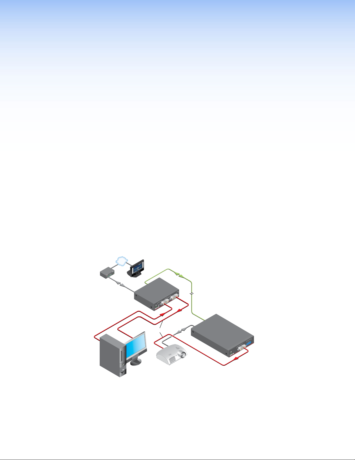
The Extron DTP DVI 230 Tx/Rx transmitter and receiver pair (see figure 1) extends the
usable distance of DVI digital video, optional analog audio, and bidirectional RS‑232 and
infrared (IR) control signals over one Extron XTP DTP 24 shielded twisted pair (STP) cable
(recommended) or Category (CAT) 5e, CAT 6, or CAT 6a STP or unshielded twisted pair
(UTP) cable. The DTP DVI 230 can also extend HDMI video, which may include embedded
audio, with the appropriate adapters. The video, audio, and control signals can be
transmitted up to 230 feet (70 m).
Control
System
TCP/IP
®
100
RELAY
LINK
ACT
31
INPUT
31
IR
42
31
COM
42
TXRX
1
IPL 250
42
2
R
3
RS-232
Extron
DTP DVI 230 Tx
Transmitter
DVI Cable
VCR
DVD
DOC
CAM
LAPTOP
PC
ON
OFF
DISPLAY
MUTE
SCREEN
UP
SCREEN
DOWN
CATx Cable
up to 230' (70 m)
LOCAL OUTPUT
DTP DVI 230 Tx
DVI-D
AUDIO
DVI Cable
INPUTS
RS-232
Extron
DTP DVI 230 Rx
Receiver
R
AUDIO
L
OUTPUTS
DTP DVI 230 Rx
DVI-D
Projector
Media PC
Figure 1. Typical Transmitter and Receiver Application
The DTP DVI 230 Tx/Rx units are housed in quarter rack width metal enclosures. They can
be set on a tabletop or mounted in a rack, under or through furniture. The receiver can also
be mounted on a projector bracket.
DTP DVI 230 Tx/Rx Transmitter and Receiver • Introduction 1
Page 8

Features
The transmitter is shipped with a single external desktop 12 VDC power supply that
accepts 100 to 240 VAC, 50‑60 Hz input. A single power supply connected to either the
transmitter or the receiver can power both units through the TP cable that carries DVI video.
TP Cable Advantages
Twisted pair cable is much smaller, lighter, more flexible, and less expensive than coaxial
or DVI cable. These transmitter and receiver twisted pair (TP) products make cable runs
simpler and less cumbersome. Termination of the cable with RJ‑45 connectors is simple,
quick, and economical.
NOTE: Do not use Extron UTP23SF‑4 Enhanced Skew‑Free AV UTP cable or
STP201 cable to link the transmitter and receiver. The DTP DVI 230 Tx/Rx does not
work properly with these cables.
Control Communications
The RS‑232 and IR communications are a passive pass‑through only. The transmitter and
receiver do not generate or respond to the RS‑232 and IR communication signals.
Transmits single link DVI signals over a single STP or UTP cable — Standard twisted
pair cables provide an economical, easily installed cable solution.
Long distance transmission — Extends video, audio, and control signals up to 230 feet
(70 m).
Supports Display Data Channel (DDC) transmission — The transmitter and receiver
pair fully supports long distance transmission of the DDC signals.
Control communications pass-through — Bidirectional RS‑232 and IR control signals
can be transmitted alongside the DVI signal, so that the remote display can be controlled
without the need for additional cabling.
Supports Consumer Electronics Control (CEC) signal transmission
1-inch high, quarter rack width, metal enclosures — With low profile enclosures, the
transmitter and receiver can be discreetly installed in locations such as behind a plasma or
LCD flat‑panel display.
External 100 VAC to 240 VAC, 50-60 Hz, international power supply — One power
supply is included with the transmitter.
Remote powering of transmitter or receiver — Only one power supply is normally
necessary to power both devices.
DTP DVI 230 Tx/Rx Transmitter and Receiver • Introduction 2
Page 9

Installation and
INPUTS
LOCAL OUTPUT
AUDIO
DVI-D
DTP DVI 230 Tx
Rx GTx
RS-232 IR
RxTx
POWER
12V
0.8 A MAX
SIG LINK
DTP OUT
OVER DTP
LOCAL
SPARE
REMOTE
1 2
ON
DDC ROUTE
1
3 2
Operation
This section describes the installation and the operation of the DTP DVI 230 Tx/Rx Extender,
including:
• Mounting the Units
• Connections
• Operation
Mounting the Units
Mounting instructions can be found in Mounting the Transmitter or Receiver on
page 10. Compatible optional hardware is listed on the Extron website (www.extron.com).
ATTENTION:
• Installation and service must be performed by authorized personnel only.
• Avoid ground potential differences between the transmitter and receiver installation
sites, which can lead to equipment damage or a missing or unstable picture. If
a potential difference cannot be avoided, remove the ground connection between
the units and locally power both units (see Disconnecting the Ground on
page 11). In this configuration, the DTP DVI 230 cannot extend analog audio and
each unit requires a local power supply.
Connections
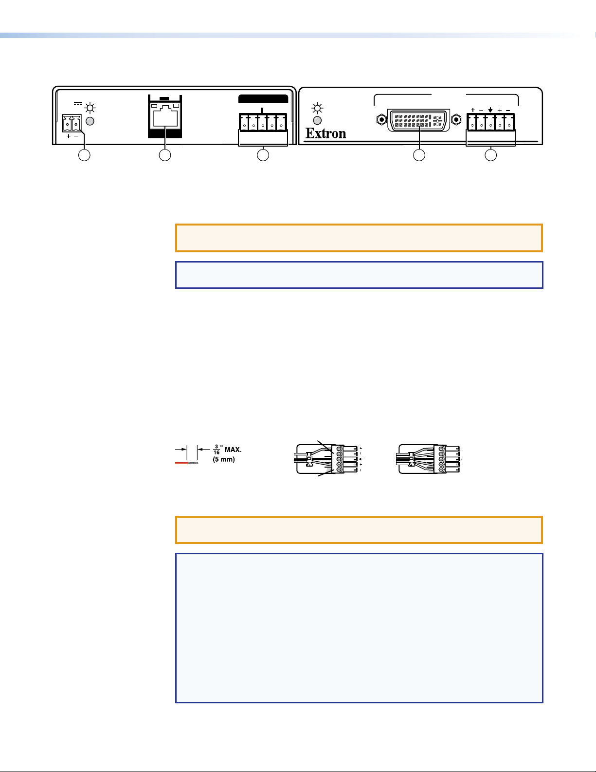
Transmitter Connections
6
5
4
FrontRear
Figure 2. DTP DVI 230 Tx Connectors
a DVI input connector — Connect an DVI cable between this port and the DVI output
port (or HDMI port, with an appropriate adapter) of the digital video source.
DTP DVI 230 Tx/Rx Transmitter and Receiver • Installation and Operation 3
Page 10

b Local Output connector — If desired, connect a DVI monitor for local monitoring of
Sleeve ( )
Ring (-)
Tip (+)
3.5 mm Stereo Plug Connector
(balanced)
the input digital image.
NOTES:
• The local output is limited to a data rate of 4.95 Gbps (1.65 Gbps per color).
• In a system where the local output is not used, ensure that you power up the
end display first before the video source. Route the DDC to the remote end
(see the DDC Route DIP switch [see item c on page 9]).
c Audio input connector — If desired, plug an analog audio input into the transmitter
via this stereo mini jack connector.
NOTE: The analog audio input on this connector is in
addition to the digital audio that may be embedded
in the DVI input. See the figure at right to identify
the connector tip, ring, and sleeve when you
are making connections for the transmitter from
existing audio cables. A mono audio connector
consists of the tip and sleeve. A stereo audio
connector consists of the tip, ring, and sleeve.
d RS-232 and IR connector — Connect a serial RS‑232 signal, a modulated IR
signal, or both to this 3.5 mm, 5‑pole captive screw connector for bidirectional RS‑232
and IR communication (see RS-232 and IR connector wiring on page 9 to wire the
connector).
e DTP Output RJ-45 connector — Connect one end of a TP cable to this RJ‑45
female connector on the transmitter. Ensure the opposite end of this cable is connected
to the receiver DTP Input RJ‑45 connector (see item g on the next page).
ATTENTION: Do not connect this device to a telecommunications or computer
data network.
NOTE: See TP cable termination and recommendations on page 6 to properly
wire the RJ‑45 connectors and for detailed NOTES.
Signal LED — Indicates the unit is receiving a TMDS clock signal on the DVI input.
Link LED — Indicates a valid link is established between the units on the DTP input
and output cable.
f Power input connector — Plug the included external 12 VDC power supply into
either this 2‑pole connector or the power input connector on the receiver (item k on
page 6). See Power supply wiring on page 8 to wire the connector.
NOTES:
• One power supply is included with the transmitter and normally can power
both units.
• If you have removed the ground jumpers (see Disconnecting the Ground
on page 11) because of ground potential differences, one DTP DVI 230 unit
cannot remotely power the other unit. Each unit requires a local power
supply.
DTP DVI 230 Tx/Rx Transmitter and Receiver • Installation and Operation 4
Page 11
Receiver Connections
FrontRear
L R
OUTPUTS
DVI-D
AUDIO
DTP DVI 230 Rx
Rx GTx
RS-232 IR
RxTx
POWER
12V
0.8 A MAX
SIG LINK
DTP IN
OVER DTP
10 9
11 87
Unbalanced Stereo Output Balanced Stereo Output
Do not tin the wires!
Tip
Ring
Tip
Ring
Sleeves
Tip
No Ground Here
No Ground Here
Tip
Sleeves
LR
LR
Figure 3. DTP DVI 230 Rx Connectors
g DTP Input RJ-45 connector — Connect one end of the TP cable from the transmitter
output connector to this RJ‑45 female connector. Ensure the opposite end of this cable
is connected to the transmitter DTP Out connector (see item e on the previous page).
ATTENTION: Do not connect this device to a telecommunications or computer
data network.
NOTE: See TP cable termination and recommendations on the next page to
properly wire the RJ‑45 connectors and for detailed NOTES.
Signal LED — Indicates the unit is receiving a valid signal on the DTP In connector.
Link LED — Indicates a valid link is established between the units on the DTP input
and output cable.
h DVI output connector — Connect a display with an DVI input port (or HDMI input
port, with an appropriate adapter) to display the transmitted direct digital image.
i Audio output connector — This 5‑pole, 3.5 mm captive screw connector outputs
the transmitted, unamplified, line level analog audio. Connect an audio device, such as
an audio amplifier or powered speakers.
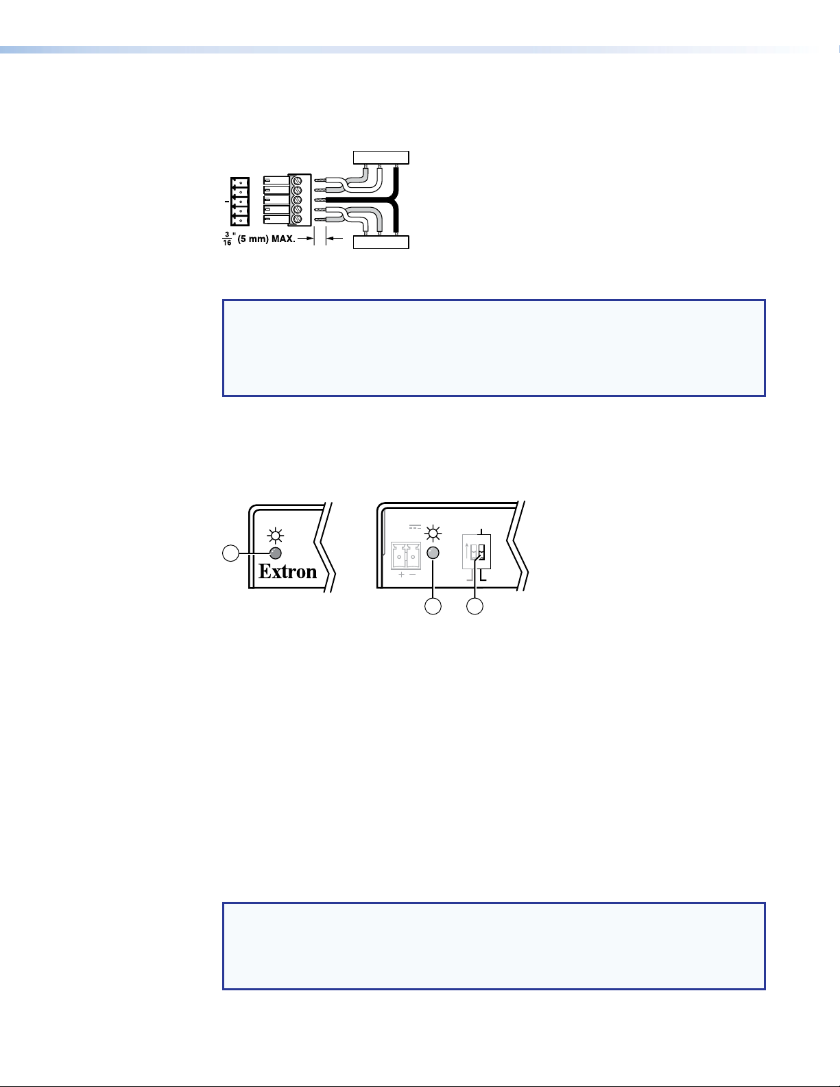
See figure 4 to properly wire a captive screw output connector. Use the supplied
tie‑wrap to strap the audio cable to the extended tail of the connector.
Figure 4. Captive Screw Connector Wiring for Stereo Audio Output
ATTENTION: For unbalanced audio, connect the sleeves to the ground contact.
Do not connect the sleeves to the negative (‑) contacts.
NOTES:
• If you have removed the ground jumpers (see Disconnecting the Ground on
page 11) because of ground potential differences, the DTP DVI 230 cannot
extend analog audio. No analog audio is output.
• The length of exposed wires is critical. The ideal length is 3/16 inch (5 mm).
• If the stripped section of wire is longer than 3/16 inch, the exposed wires
may touch, causing a short circuit.
• If the stripped section of wire is shorter than 3/16 inch, wires can be easily
pulled out even if tightly fastened by the captive screws.
• Do not tin the power supply leads before installing them in the connector.
Tinned wires are not as secure in the connector and could be pulled out.
DTP DVI 230 Tx/Rx Transmitter and Receiver • Installation and Operation 5
Page 12

j RS-232 and IR connector — Connect a serial RS‑232 signal, a modulated IR
signal, or both to this 3.5 mm, 5‑pole captive screw connector for bidirectional RS‑232
and IR communication (see RS-232 and IR connector wiring on page 9 to wire the
connector).
k Power input connector — Plug the included external 12 VDC power supply into
either this 2‑pole connector or the power input connector on the transmitter (see
item f on the previous page) (see Power supply wiring on page 8 to wire the
connector).
NOTES:
• One power supply is included with the transmitter and normally can power
both units.
• If you have removed the ground jumpers (see Disconnecting the Ground
on page 11) because of ground potential differences, one DTP DVI 230 unit
cannot remotely power the other unit. Each unit requires a local power
supply.
Connector and Cable Details
TP cable termination and recommendations
Figure 5 details the TIA/EIA T 568B wiring standard. Use this standard to terminate TP
cables with RJ‑45 connectors.
Side
Pins:
12345678
TIA/EIA T
568 B
Pin
Wire color
White-orange
1
Orange
2
3
White-green
4
Insert
Twisted
Pair Wires
Blue
5
White-blue
6
Green
7
White-brown
8
Brown
Figure 5. TP Cable Termination
NOTE: Do not use Extron UTP23SF‑4 Enhanced Skew‑Free AV UTP cable or STP201
cable to link the transmitter and receiver. The DTP DVI 230 Tx/Rx does not work
properly with these cables.
DTP DVI 230 Tx/Rx Transmitter and Receiver • Installation and Operation 6
Page 13

Supported cables —
The DTP DVI 230 is compatible with CAT 5e, 6, 6a, and 7 shielded twisted pair (F/UTP,
SF/UTP, and S/FTP) and unshielded twisted pair (U/UTP) cable.
Cable recommendations —
Extron recommends using the following practices to achieve full transmission distances up
to 230 feet (70 m) and reduce transmission errors.
• Use the following Extron XTP DTP 24 SF/UTP cables and DTP 24 connectors for the
best performance:
• XTP DTP 24/1000 Non‑Plenum 1000’ (305 m) spool 22‑236‑03
• XTP DTP 24P/1000 Plenum 1000’ (305 m) spool 22‑235‑03
• XTP DTP 24 Plug Package of 10 101‑005‑02
• If not using XTP DTP 24 cable, at a minimum, Extron recommends 24 AWG, solid
conductor, STP cable with a minimum bandwidth of 400 MHz.
• Terminate cables with shielded connectors to the TIA/EIA T 568 B standard.
• Use no more than two pass‑through points, which may include patch points, punch
down connectors, couplers, and power injectors. If these pass‑through points are
required, use CAT 6 or 6a shielded couplers and punch down connectors.
NOTE: When using CAT5e and CAT6 cable in bundles or conduits, consider the
following:
• Do not exceed 40% fill capacity in conduits.
• Do not comb the cable for the first 20 meters, where cables are straightened,
aligned, and secured in tight bundles.
• Loosely place cables and limit the use of tie wraps or Velcro®.
• Separate twisted pair cables from AC power cables.
DTP DVI 230 Tx/Rx Transmitter and Receiver • Installation and Operation 7
Page 14

Power supply wiring
Power Supply
Output Cord
SECTION A–A
Ridges
Smooth
AA
Tie Wrap
3
5
NOTES:
• One power supply is included with the transmitter and normally can power both
units.
• If you have removed the ground jumpers (see Disconnecting the Ground on
page 11) because of ground potential differences, one DTP DVI 230 unit cannot
remotely power the other unit. Each unit requires a local power supply.
Figure 6 shows how to wire the connector. Use the supplied tie‑wrap to strap the power
cord to the extended tail of the connector.
Figure 6. Power Connector Wiring
CAUTION: Electric shock hazard —
• The two power cord wires must be kept separate while the power supply is
plugged in. Remove power before wiring.
• The length and preparation of exposed wires is important (see the second and
third audio connector NOTES on page 5 for details).
ATTENTION:
• This product is intended to be supplied by a Listed Power Unit marked “Class 2”
or “LPS,” rated 12 VDC, 1.0 A minimum. Always use a power supply supplied by
or specified by Extron. Use of an unauthorized power supply voids all regulatory
compliance certification and may cause damage to the supply and the end product.
• Unless otherwise stated, the AC/DC adapters are not suitable for use in air
handling spaces or in wall cavities.
• The installation must always be in accordance with the applicable provisions of
National Electrical Code ANSI/NFPA 70, article 75 and the Canadian Electrical
Code part 1, section 16. The power supply shall not be permanently fixed to a
building structure or similar structure.
• Power supply voltage polarity is critical. Incorrect voltage polarity can damage the
power supply and the unit. The ridges on the side of the cord (see figure 6) identify
the power cord negative lead.
To verify the polarity before connection, plug in the power supply with no load and check the
output with a voltmeter.
DTP DVI 230 Tx/Rx Transmitter and Receiver • Installation and Operation 8
Page 15
Operation
LOCAL
SPARE
REMOTE
1 2
ON
DDC ROUTE
POWER
12V
0.8 A MAX
Rear
(Tx)
Front
(Both Units)
2 3
1
RS-232 and IR connector wiring
Figure 7 shows how to wire the RS‑232 connector.
IR Device
TxRx
Tx/Rx
Pins
RxTx
Rx GTx
RS-232 IR
Figure 7. RS-232 Connector Wiring
NOTES:
• The IR Tx and Rx line pair and the RS‑232 Tx and Rx line pair must each cross
once between this connector and the source or destination.
• The length and preparation of exposed wires is important (see the second and
third audio connector NOTES on page 5 for details).
Figure 8 shows the location of the power indicators on the front and rear panels of the
transmitter and receiver.
Gnd
RxTx
Gnd
RS-232 Device
Figure 8. Power Indicators
a Power (and signal) LED (front panel) —
Amber — The unit is receiving power, either locally or remotely (on the DTP cable).
Green — The unit is receiving an active DVI input, either on the DVI input if a
transmitter, or transmitted on the DTP cable if a receiver.
b Power LED (rear panel) —
Amber — The unit is receiving power remotely (on the DTP cable).
Green — The unit is receiving power locally.
c DDC Route switch — This rear panel switch selects either the remote or local DVI
display as the DDC reference (for EDID communications).
After the transmitter, the receiver, and their connected devices are powered up, the system is
fully operational. If any problems are encountered, ensure all cables are routed and
connected properly.
NOTE: Ensure that the video source and display selected for the DDC are properly
connected to the transmitter and receiver pair, and that the transmitter, the receiver,
and the display have power applied before power is applied to the video source.
If the other devices are not turned on before the video source, the image may not
appear.
DTP DVI 230 Tx/Rx Transmitter and Receiver • Installation and Operation 9
Page 16

Reference
Information
This section provides procedures for mounting the DTP DVI 230 Tx/Rx transmitter and
receiver and disconnecting the ground between them.
• Mounting the Transmitter or Receiver
• Disconnecting the Ground
Mounting the Transmitter or Receiver
ATTENTION:
• Installation and service must be performed by authorized personnel only.
• Avoid ground potential differences between the transmitter and receiver installation
sites, which can lead to equipment damage or a missing or unstable picture. If
a potential difference cannot be avoided, remove the ground connection between
the units and locally power both units (see Disconnecting the Ground on the
next page).
The 1‑inch high, quarter rack width DTP DVI 230 transmitter or receiver can be placed on
a table, mounted in a rack, or mounted under a desk or table. The receiver can also be
mounted on a projector bracket.
Tabletop Use
Affix the included rubber feet to the bottom of the unit and place it in any convenient
location.
Mounting kits
Mount the unit using any optional compatible mounting kit listed on the Extron website
(www.extron.com), in accordance with the directions included with the kit. For rack
mounting, see UL Rack-Mounting Guidelines on the next page.
DTP DVI 230 Tx/Rx Transmitter and Receiver • Reference Information 10
Page 17
UL Rack-Mounting Guidelines
The following Underwriters Laboratories (UL) requirements pertain to the installation of the
unit into a rack.
• Elevated operating ambient temperature — If installed in a closed or multi‑unit rack
assembly, the operating ambient temperature of the rack environment may be greater
than room ambient. Therefore, consider installing the equipment in an environment
compatible with the maximum ambient temperature (TMA = +122 °F, +50 °C) specified
by Extron.
• Reduced air flow — Installation of the equipment in a rack should be such that the
amount of air flow required for safe operation of the equipment is not compromised.
• Mechanical loading — Mounting of the equipment in the rack should be such that a
hazardous condition is not achieved due to uneven mechanical loading.
• Circuit overloading — Consideration should be given to the connection of the
equipment to the supply circuit and the effect that overloading of the circuits might have
on overcurrent protection and supply wiring. Appropriate consideration of equipment
nameplate ratings should be used when addressing this concern.
• Reliable earthing (grounding) — Reliable earthing of rack‑mounted equipment
should be maintained. Particular attention should be given to supply connections other
than direct connections to the branch circuit (such as use of power strips).
Disconnecting the Ground
If you cannot resolve a ground potential difference between the transmitter and receiver
installation sites (as suggested by a missing or unstable picture), remove the ground
connection between the units as follows:
NOTE: Once you have removed the ground jumpers, the DTP DVI 230 cannot extend
analog audio and one unit cannot remotely power the other. No analog audio is
output and each unit requires a local power supply.
1. Disconnect any cables and remove the transmitter and receiver from any rack or other
installation option.
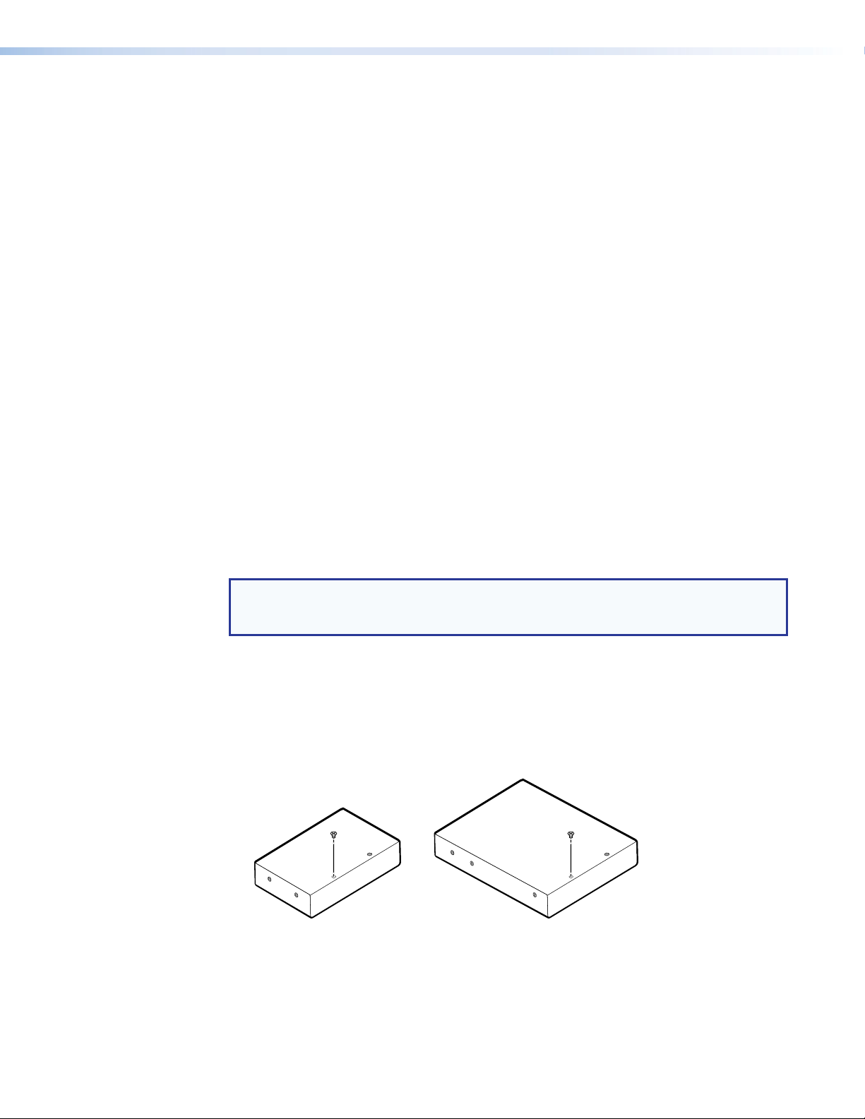
2. Remove and retain the screws securing the covers to the transmitter and receiver. Slide
the covers forward slightly and lift them off both units (see figure 9).
• Transmitter — Six screws, two on each side and two on top
• Receiver — Eight screws, three on each side and two on top
Cover Screws
(6 Plcs)
Rear Panel Rear Panel
Transmitter Receiver
Cover Screws
(8 Plcs)
Figure 9. Opening the Transmitter and Receiver
DTP DVI 230 Tx/Rx Transmitter and Receiver • Reference Information 11
Page 18
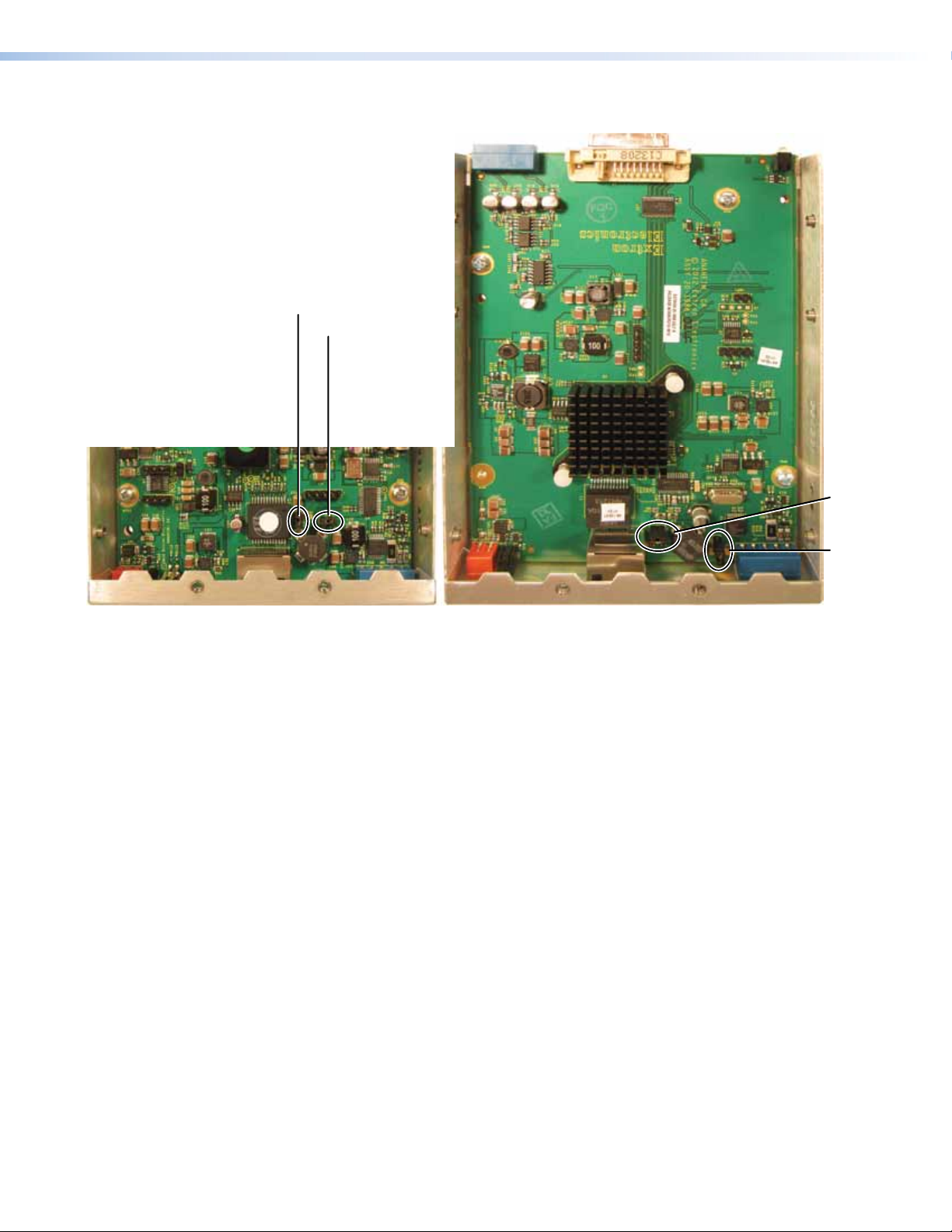
3. Locate, lift off, and discard jumpers JMP2 and JMP3 from both units (see figure 10).
rR
MP3
JMP2
JMP2
JMP3
J
Transmitte
eceiver
Figure 10. Jumper Locations
4. Reinstall the covers on both units, securing them in place with the screws removed in
step 2.
5. Reinstall both units in their racks or other installation option (see Mounting the
Transmitter and Receiver on page 10).
6. If you are using shielded cable, disconnect the cable shield from the connector at
either end of the cable.
7. Obtain a second 12 V power supply (one supply is provided with the transmitter and
normally powers both units), and locally power both units (see Power supply wiring
on page 8).
DTP DVI 230 Tx/Rx Transmitter and Receiver • Reference Information 12
Page 19

Extron Warranty
Extron Electronics warrants this product against defects in materials and workmanship for a period of three years
from the date of purchase. In the event of malfunction during the warranty period attributable directly to faulty
workmanship and/or materials, Extron Electronics will, at its option, repair or replace said products or components,
to whatever extent it shall deem necessary to restore said product to proper operating condition, provided that it is
returned within the warranty period, with proof of purchase and description of malfunction to:
USA, Canada, South America,
and Central America:
Extron Electronics
1230 South Lewis Street
Anaheim, CA 92805
U.S.A.
Europe and Africa:
Extron Europe
Hanzeboulevard 10
3825 PH Amersfoort
The Netherlands
Japan:
Extron Electronics, Japan
Kyodo Building, 16 Ichibancho
Chiyoda‑ku, Tokyo 102‑0082
Japan
China:
Extron China
686 Ronghua Road
Songjiang District
Shanghai 201611
China
Asia:
Extron Asia Pte Ltd
135 Joo Seng Road, #04‑01
PM Industrial Bldg.
Singapore 368363
Middle East:
Extron Middle East
Dubai Airport Free Zone
F12, PO Box 293666
United Arab Emirates, Dubai
Singapore
This Limited Warranty does not apply if the fault has been caused by misuse, improper handling care, electrical
or mechanical abuse, abnormal operating conditions, or if modifications were made to the product that were not
authorized by Extron.
NOTE: If a product is defective, please call Extron and ask for an Application Engineer to receive an RA (Return
Authorization) number. This will begin the repair process.
USA: 714.491.1500 or 800.633.9876 Europe: 31.33.453.4040
Asia: 65.6383.4400 Japan: 81.3.3511.7655
Units must be returned insured, with shipping charges prepaid. If not insured, you assume the risk of loss or damage
during shipment. Returned units must include the serial number and a description of the problem, as well as the
name of the person to contact in case there are any questions.
Extron Electronics makes no further warranties either expressed or implied with respect to the product and its quality,
performance, merchantability, or fitness for any particular use. In no event will Extron Electronics be liable for direct,
indirect, or consequential damages resulting from any defect in this product even if Extron Electronics has been
advised of such damage.
Please note that laws vary from state to state and country to country, and that some provisions of this warranty may
not apply to you.
Extron Headquarters
+1.800.633.9876 (Inside USA/Canada Only)
Extron USA - West Extron USA - East
+1.714.491.1500 +1.919.850.1000
+1.714.491.1517 FAX +1.919.850.1001 FAX
Extron Europe
+800.3987.6673
(Inside Europe Only)
+31.33.453.4040
+31.33.453.4050 FAX
© 2013 Extron Electronics All rights reserved. www.extron.com
Extron Asia
+65.6383.4400
+65.6383.4664 FAX
Extron Japan
+81.3.3511.7655
+81.3.3511.7656 FAX
Extron China
+86.21.3760.1568
+86.21.3760.1566 FAX
Extron Middle East
+971.4.299.1800
+971.4.299.1880 FAX
Extron Korea
+82.2.3444.1571
+82.2.3444.1575 FAX
Extron India
1800.3070.3777
(Inside India Only)
+91.80.3055.3777
+91.80.3055.3737 FAX
 Loading...