

Page 1
Installation Guide
CVC 300
Component Video and HDTV to RGB Converter
68-1541-01 Rev. B
12 08
Page 2
LAN
ACT
LINK
RESET
7
8
5
6
3
4
1
2
7
8
5
6
3
4
1
2
7
8
5
6
3
4
1
2
7
8
5
6
3
4
1
2
7
8
5
6
3
4
1
2
OUTPUTS
OUTPUTS
15
16
13
14
11
12
9
10
7
8
5
6
3
4
1
2
15
16
13
14
11
12
9
10
7
8
5
6
3
4
1
2
15
16
13
14
11
12
9
10
7
8
5
6
3
4
1
2
15
16
13
14
11
12
9
10
7
8
5
6
3
4
1
2
15
16
13
14
11
12
9
10
7
8
5
6
3
4
1
2
INPUTS
INPUTS
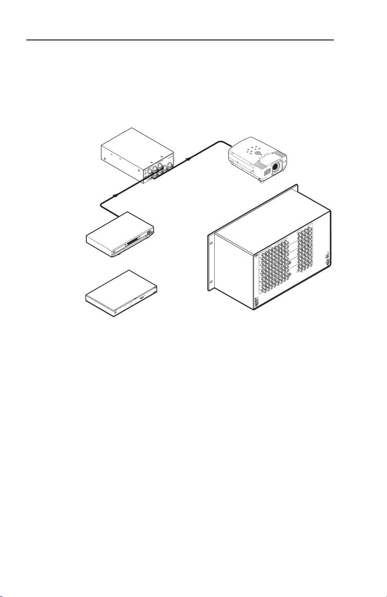
Matrix Switcher
Projector
RGBHV
Component
POWER
12V
3A MAX
CVC 300
OUTPUT
R
G B V
H/HV
PR/R
PB/B
Y/G
INPUT
DSS Receiver
or
or
Blu-ray Disc
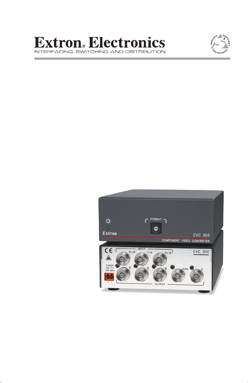
Extron
CVC 300
Component Video
Converter
Introduction
The Extron CVC 300 Component Video Converter converts all
standard component video formats: NTSC/PAL, DVD, and
Betacam®, to RGBHV or RGBS; and converts SMPTE HDTV
component video to RGBHV. The CVC 300 can also strip
sync-on-green (SOG) from RGsB video. The converter outputs
RGBHV or RGBS video on BNC connectors. The figure below
shows a typical CVC 300 application.
Mounting
1
The component video input formats include SMPTE, HDTV
and Betacam component video. The RGsB video input can be
computer video or NTSC/PAL video.
The 1U high, quarter rack width, CVC 300 converter can be
mounted to a rack, under a desk or tabletop, or on a projector
bracket. It can be rack mounted using one-quarter of a 1U
Universal Rack Shelf, RSU 129 (part #60-190-01) or 1U Basic
UL rack mounting guidelines
Rack Shelf, RSB 129 (part #60-604-01).
The following Underwriters Laboratories (UL) guidelines
pertain to the installation of the CVC 300 into a rack.
Elevated operating ambient temperature — If the 1.
equipment is installed in a closed or multi-unit rack
assembly, the operating ambient temperature of the
rack environment may be greater than room ambient
temperature. Therefore, install the converter in an
environment compatible with the maximum ambient
temperature (Tma = +104 °F, +40 °C) specified by Extron.
CVC 300 • Installation
Page 3
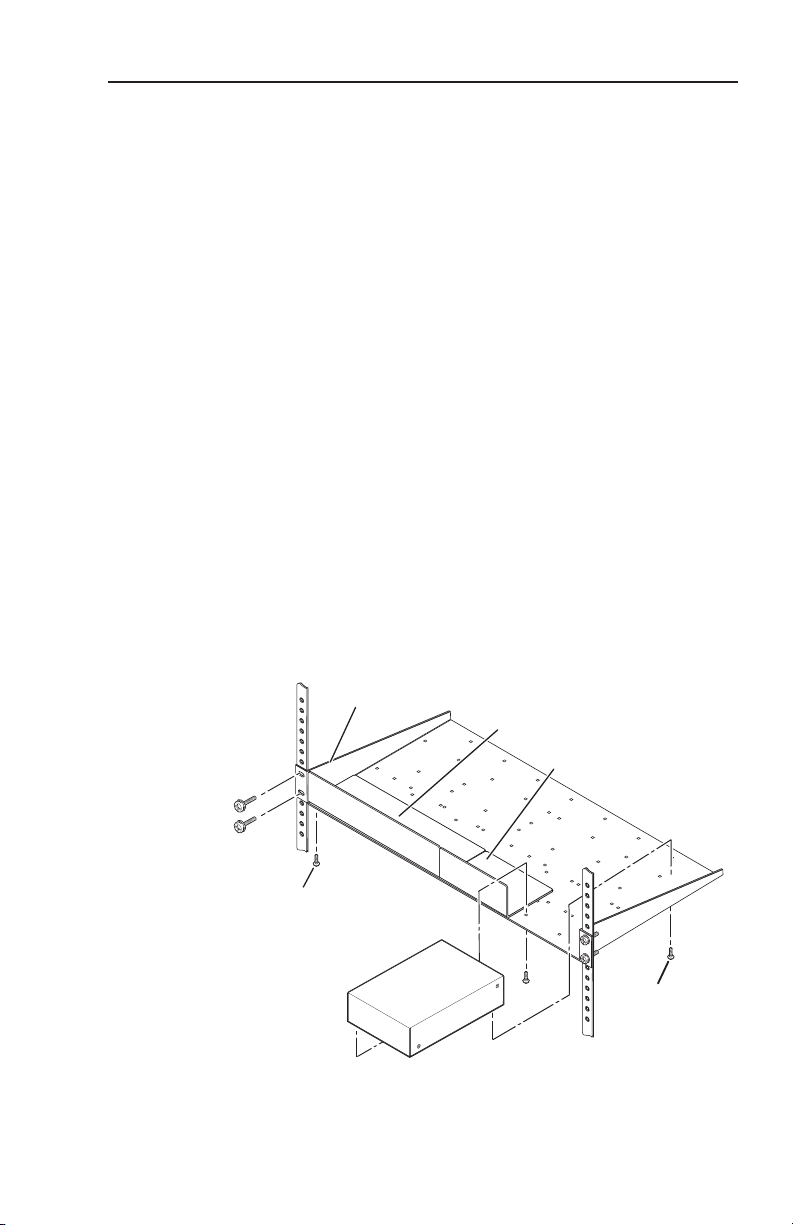
Use 2 mounting holes on
opposite corners.
(2) 4-40 x 3/16"
Screws
1U Universal Rack Shelf
Both front false faceplates
use 2 screws.
QuarterRackStandardShelf
1/4 Rack Width Front False
Faceplate
1/2 Rack Width Front False
Faceplate
Mounting
Reduced air flow — Install the equipment in a rack so that 2.
the amount of air flow required for safe operation of the
equipment is not compromised.
Mechanical loading — Mount the equipment in the rack so 3.
that a hazardous condition is not achieved due to uneven
mechanical loading.
Circuit overloading — Connect the equipment to 4.
the supply circuit and consider the effect that circuit
overloading might have on overcurrent protection and
supply wiring. Appropriate consideration of equipment
nameplate ratings should be used when addressing this
concern.
Reliable earthing (grounding) — Maintain reliable 5.
grounding of rack-mounted equipment. Pay particular
attention to supply connections other than direct
connections to the branch circuit (e.g. use of power strips).
Mounting instructions
Rack mount the CVC 300 as follows:
Remove the feet from the CVC, if they were previously 1.
installed.
Mount the CVC 300 on the rack shelf, using two 2.
4-40 x 3/16" screws in opposite corners (under the shelf) to
secure the converter to the shelf (see below).
CVC 300 • Installation
2
Page 4

Cable Connection and Rate Selection
POWER
12V
1.0 A MAX
CVC 300
OUTPUT
R
GB V
H/HV
P
R
/R
P
B
/B
Y/G
INPUT
COMPONENT VIDEO CONVERTER
CVC 300
FORMAT
c
e
b
a
d
Y, PR, PB
Video
RGsB
(SOG)
Video
Y, B-Y, R-Y
Video
B-YR-Y
PR /R PB /BY/G
PR /R PB /BY/G
PR /R PB /BY/G
R G B
H/HV
V
RGBHV
Video
RGBS
Video
R G B H/HV V
Cable Connection and Rate Selection
See the illustrations below to identify the panel connections.
Power connector — Plug the external 12 VDC power supply
a
here using the included 2-pole captive screw connector
(See "Power supply wiring").
Input connectors — Connect a component (SMPTE, HDTV,
b
or Betacam) or RGsB video input device to these female BNC
connectors. Connect the input device as shown below.
Output connectors — Connect an RGBHV or RGBS display to
c
these female BNC connectors. Connect the display as shown
below.
Power LED — Green when power is applied and an active
d
video input is detected. Amber if power is available but no
input signal is present.
3
CVC 300 • Cable Connection
Page 5
Cable Connection and Rate Selection (Cont’d)
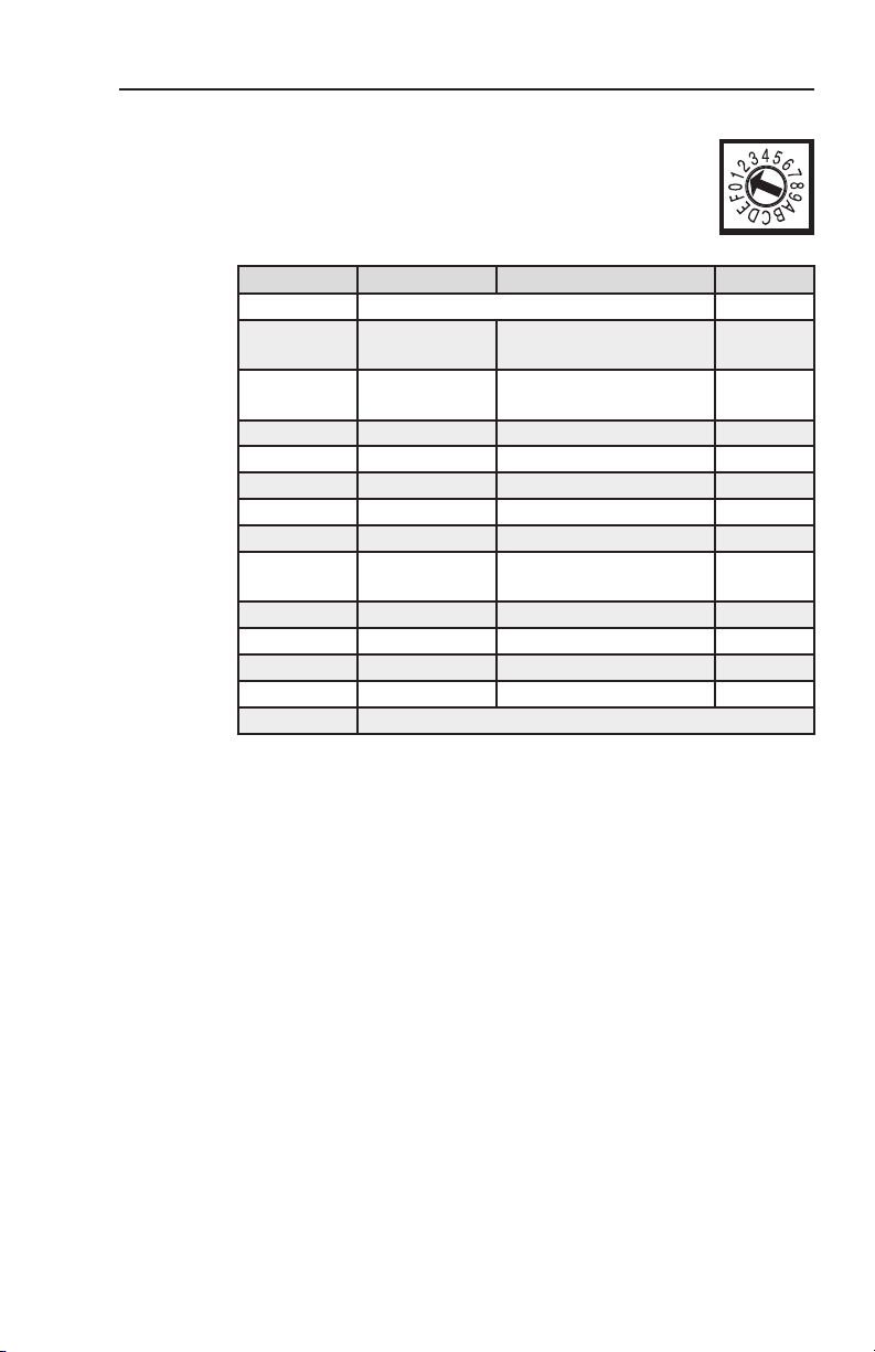
Input Format rotary switch — Use an Extron
e
Tweeker or other small screwdriver to set the Format
rotary switch to match the video input format. The
following table shows switch settings and their
assigned input video formats.
Position Input Resolutions Output
Position 0 Reserved for future use
Position 1
(Default):
Position 2: RGsB
Position 3: YUVi 480i, 576i RGBHV
Position 4: RGsB HD 720p, 1080i, 1080p RGBHV
Position 5: Betacam 50 480i, 576i RGBHV
Position 6: Betacam 60 480i, 576i RGBHV
Position 7: YUVp 480p, 576p RGBS
Position 8 RGsB
Position 9: YUVi 480i, 576i RGBS
Position A: RGsB HD 720p, 1080i, 1080p RGBS
Position B: Betacam 50 480i, 576i RGBS
Position C: Betacam 60 480i, 576i RGBS
D, E and F Reserved for future use
Input Format Table (Rotary Switch)
YUVp/HD
480p, 576p, 720p,
1080i, 1080p
480i/p, 576i/p,
640x480 to 1920x1200
480i/p, 576i/p,
640x480 to 1920x1200
RGBHV
RGBHV
RGBS
CVC 300 • Rate Selection
4
Page 6

Power Supply Wiring
Captive Screw Connector
SECTION A–A
Power Supply
Output Cord
Ridges
A
Smooth
A
Tie Wrap
+ _
3
5
Power supply wiring
N
Wire the supplied male power connector (plug) as shown below.
This product is intended to be powered by a UL Listed
power supply with an output rated at 12 VDC, 2 A.
C
N
To verify the polarity before connection, plug in the power
supply with no load and check the output with a voltmeter.
W
As an alternative, an Extron PS 123 Universal 12 VDC Power
Supply, part #60-814-01, can power multiple Extron 12 VDC
devices using only one AC power connector.
Insert the wired plug into the power connector on the rear
panel, then connect AC power.
Power supply voltage polarity is critical. Incorrect
polarity can damage the power supply and the product.
Identify the power cord negative lead by the ridges on the
side of the cord.
The length of the exposed (stripped) copper wires is
important. The ideal length is 3/16” (5 mm). Longer bare
wires can short together. Shorter wires are not as secure in
the captive screw connectors and could be pulled out.
Do not tin the stripped power supply leads. Tinned wires
are not as secure in the captive screw connectors and could
be pulled out.
The two power cord wires must be kept separate while
the power supply is plugged in. Remove power before
wiring.
CVC 300 • Power Supply Wiring
5
Page 7

Specifications
Video input
Number/signal type ..................... 1 component video [HDTV
(Y, PR, PB), SMPTE (Y, R-Y, B-Y), or
Betacam® (Y, R-Y, B-Y)] or RGsB
Connectors ..................................... 3 BNC female
Nominal level ................................ 1 Vp-p for Y of component video and
for G of RGsB
0.7 Vp-p for PB, PR, R-Y and B-Y of
component video, and for R and B of RGsB
Minimum/maximum levels ........ 0 V to 1.5 Vp-p with no offset
Impedance ...................................... 75 ohms
Horizontal frequency .................... 15 kHz to 100 kHz according to selected
mode
Vertical frequency .......................... 50 Hz to 120 Hz
Resolution range ........................... 640x480 to 1920x1200, 480i/p, 576i/p,
720p, 1080i/p
Return loss ...................................... <-35 dB @ 10 MHz
Video output
Number/signal type ..................... 1 RGBHV, RGBS
Connectors ..................................... 5 BNC female
Nominal level ................................ 0.7 Vp-p for RGB
Minimum/maximum levels ........ RGB: 0.0 V to 0.7 Vp-p
Impedance ...................................... 75 ohms
Return loss ...................................... <-45 dB @ 10 MHz
Vertical frequencies ....................... Locked to the detected input rate
Sync
Input type ....................................... RGsB; YUV; Y, R-Y, B-Y
Output type .................................... RGBHV, RGBS
Standards ........................................ SMPTE 170M (NTSC), SMPTE 274M
(1080i/p), SMPTE 293M (480p), SMPTE
296M (720p)
Input level ...................................... 0.3 V to 1.0 Vp-p (sync + video)
Output level ................................... 0.0 V to 5.0 Vp-p
Input impedance ........................... 75 ohms (on Y or Gs connector)
Output impedance ........................ 75 ohms (on H/HV and V connectors)
CVC 300 • Specications
6
Page 8

Extron USA - West
Headquarters
+800.633.9876
Inside USA / Canada Only
+1.714.491.1500
+1.714.491.1517 FAX
Extron USA - East
+800.633.9876
Inside USA / Canada Only
+1.919.863.1794
+1.919.863.1797 FAX
Extron Europe
+800.3987.6673
Inside Europe Only
+31.33.453.4040
+31.33.453.4050 FA X
Extron Asia
+800.7339.8766
Inside Asia Only
+65.6383.4400
+65.6383.4664 FAX
Extron Japan
+81.3.3511.7655
+81.3.3511.7656 FAX
Extron China
+400.883.1568
Inside China Only
+86.21.3760.1568
+86.21.3760.1566 FAX
Extron Middle East
+971.4.2991800
+971.4.2991880 FAX
Specifications (Cont’d)
General
External power supply ................. 100 VAC to 240 VAC, 50-60 Hz, external;
to 12 VDC, 2 A, regulated
Power input requirements ........... 12 VDC, 1.0 A
Temperature/humidity ................ Storage: -40 to +158 °F (-40 to +70 °C) /
10% to 90%, noncondensing
Operating: +32 to +104 °F (0 to +40 °C) /
10% to 90%, noncondensing
Cooling ........................................... Convection, no vents
Mounting
Rack mount ........................ Yes, with optional 1U, 9.5" deep rack shelf
(RSU 129, #60-190-01; RSB 129, 60-604-01);
or 1U, 6" deep rack shelf (RSU 126,
#60-190-10; RSB 126, 60-604-10)
Furniture mount ................ Yes, with optional MBU 125 Under
Desk Mount kit (70-077-01) or MBU 129
Through Desk Mount kit (70-077-02)
Enclosure type ............................... Metal
Enclosure dimensions ................... 1.7" H x 4.3" W x 6.0" D (1U high, quarter
rack wide)
(4.3 cm H x 10.9 cm W x 15.2 cm D)
(Depth excludes connectors.)
Product weight .............................. 0.8 lbs (0.4 kg)
Shipping weight ............................ 2 lbs (1 kg)
Vibration ......................................... ISTA 1A in carton (International Safe
Transit Association)
Regulatory compliance
Safety ................................... CE, CUL, UL
EMI/EMC .......................... CE, C-tick, FCC Class A, ICES,
VCCI Class A
MTBF ............................................... 30,000 hours
Warranty ......................................... 3 years parts and labor
N
N
All nominal levels are at ±10%.
Specifications are subject to change without notice.
© 2008 Extron Electronics. All rights reserved.
 Loading...