

Page 1
CAUTION
Specifications
Video input — RGB 580
Number/signal type .......................... 1 analog RGBHV, RGBS, RGsB, RsGsBs
Connectors ........................................... 1 15-pin HD female
Video output — RGB 580
Number/signal type .......................... 1 analog RGBHV, RGBS, RGsB
Connectors ........................................... 1 15-pin HD female
xixi
xi
AAP / CCS AAP / CCSI AAP
xixi
xixi
xi
AAP / CCS AAP / CCSI AAP
xixi
General
Temperature/humidity ..................... Storage -40° to +158°F (-40° to +70°C) / 10%
to 90%, non-condensing
Operating +32° to +122°F (0° to +50°C) / 10%
to 90%, non-condensing
Enclosure dimensions
RGB 580xi AAP/Cable Cubby AAP models (double-height plates)
Faceplate ................................ 1.4" H x 3.5" W (3.6 cm H x 8.9 cm W)
Circuit board ......................... 1.3" H x 2.5" W x 0.9" D
(3.3 cm H x 6.4 cm W x 2.3 cm D) Depth
excludes connectors and knobs.
Shipping weight .................................. AAP models . 1 lb (0.5 kg)
Vibration .............................................. ISTA/NSTA 1A in carton (International Safe
Transit Association)
Approvals ............................................ UL, CUL, CE, FCC Class A
MTBF .................................................... 30,000 hours
Warranty .............................................. 3 years parts and labor
User’s Guide
www.extron.com
Extron Electronics, USA
1230 South Lewis Street
Anaheim, CA 92805
USA
714.491.1500
Fax 714.491.1517
Specifications are subject to change without notice.
Extron Electronics, Europe
Beeldschermweg 6C
3821 AH Amersfoort
The Netherlands
+31.33.453.4040
Fax +31.33.453.4050
© 2006 Extron Electronics. All rights reserved.
Extron Electronics, Asia
135 Joo Seng Road, #04-01
PM Industrial Building
Singapore 368363
+65.6383.4400
Fax +65.6383.4664
Extron Electronics, Japan
Kyodo Building
16 Ichibancho
Chiyoda-ku, Tokyo 102-0082 Japan
+81.3.3511.7655
Fax +81.3.3511.7656
RGB 580
RGB 580
xixi
xi
AAP/CC AAP Series
xixi
xixi
xi AAP, RGB 580
xixi
RGB 580
xixi
xi S/CCS AAP,
xixi
xixi
xi SI/CCSI AAP
xixi
68-537-01 Rev. C
03 06
Page 2
○○○○○○○○○○○○○○○○○○○○○○○○○○○○○○○○○○○○○○○○○○○○○○○○○○○○○○○○○○○○○○○○○○○○○○○○○○○○○○○○○○○○○○○○○○○○○○○○○○○○
CAUTION
Installation and Operation
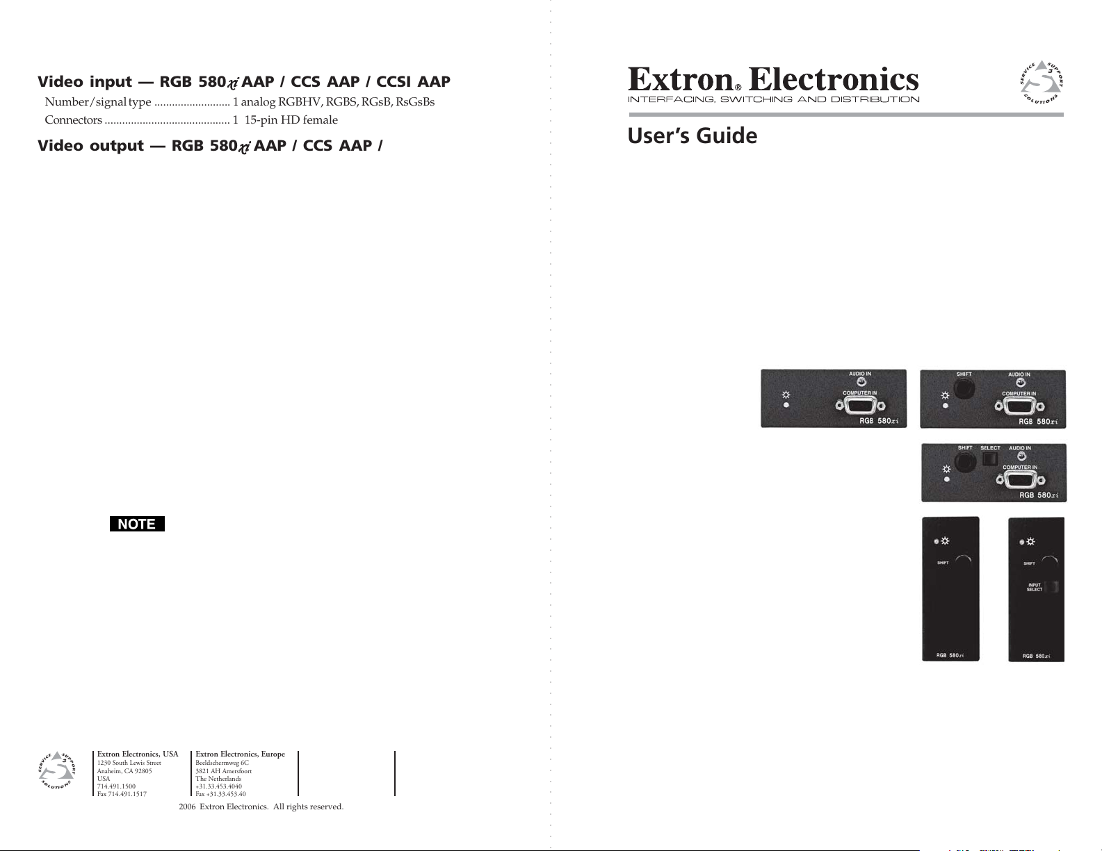
Extron’s RGB 580xi AAP double-space devices are designed to
complement the RGB 580xi remote interface. They may be
mounted to any Extron product which has an AAP faceplate or to
an AAP wallplate. See the “AAP Device Part Numbers” and the
“Cable Cubby AAP Device Part Numbers” sections for AAP/CC
AAP part numbers.
RGB 580
xixi
xi AAP/CC AAP Series Features
xixi
RGB 580xi AAP
1
4
RGB 580xi CCS AAP
SHIFT
1
Power/signal LED — This LED lights
1
AUDIO IN
COMPUTER IN
RGB 580xi
2
RGB 580xi
4
SHIFT
COMPUTER IN
1
1
SHIFT
1
2
4
SELECT
COMPUTER IN
5
2
4
SHIFT
• amber to indicate that the AAP device is receiving
power.
• green to indicate that an active sync signal is present at
the input and the AAP device is receiving power.
The LED will flash green whenever the minimum and
maximum limits of the horizontal shift control (H. shift)
have been reached.
33
RGB 580xi S AAP
AUDIO IN
RGB 580xi
3
RGB 580xi SI AAP
AUDIO IN
RGB 580xi
RGB 580xi CCSI AAP
INPUT
SELECT
5
Installation and Operation
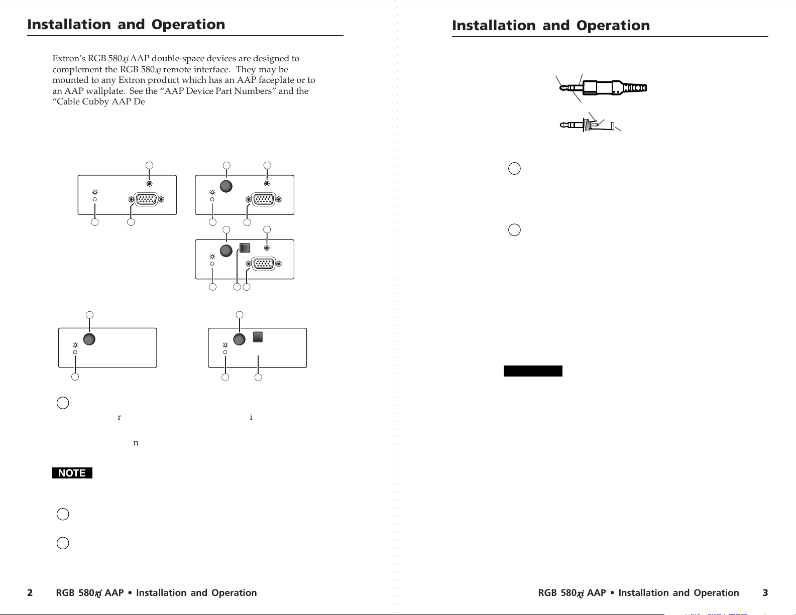
Tip (L) Sleeve (GND)
Ring (R)
Tip (L)
Sleeve (GND)
Audio input wiring
Horizontal shift control knob — While viewing the
4
displayed image, rotate this control to move the image to
the right or left on the screen. The power/signal LED will
flash green whenever the minimum and maximum limits
of this control are reached.
Input select button — Pressing this button will result in
5
contact closure between pins A and B of the contact closure
control connector on the front panel of the RGB 580xi
remote interface. This button can also be used for direct
control of any Extron contact closure-controlled switcher,
or as a direct connection to an external control system.
Mounting the RGB 580
The AAP device should be cabled before attaching the AAP
device to a faceplate or wallplate. The screws needed for
installing an AAP device are built into its front panel, so no
RGB 580xi
additional screws will be needed.
Installation and service must be performed by
authorized personnel only.
1. Connect the output cables to the AAP device’s rear
connectors. See the section “Cabling the AAP/Cable Cubby
AAP Device Rear Connectors” in this user’s guide.
2. Insert the AAP device’s screws through the holes in the AAP
double-space faceplate, the AAP wallplate, or the Cable
Cubby AAP shelf bracket. Secure the AAP device to the
faceplate/wallplate/shelf bracket with the provided captive
washers and #4-40 nuts.
xixi
xi AAP Device
xixi
Computer video input connector — Attach a cable from
2
the computer source to this 15-pin HD female connector.
Audio input connector — Plug a 3.5 mm stereo plug into
3
this jack for unbalanced audio input. Wire the male plug as
shown in the following illustration.
RGB 580
xixi
xi AAP • Installation and Operation
xixi
RGB 580
○○○○○○○○○○○○○○○○○○○○○○○○○○○○○○○○○○○○○○○○○○○○○○○○○○○○○○○○○○○○○○○○○○○○○○○○○○○○○○○○○○○○○○○○○○○○○○○○○○○○○○○○○○○○○○○○○○○○○○○○○○○○○○○○○○○○○○○○○○○○○○○○○○○○○○○○○○○
xixi
xi AAP • Installation and Operation
xixi
32
Page 3

○○○○○○○○○○○○○○○○○○○○○○○○○○○○○○○○○○○○○○○○○○○○○○○○○○○○○○○○○○○○○○○○○○○○○○○○○○○○○○○○○○○○○○○○○○○○○○○○○○○○○○○○○○○○○○○○○○○○○○○○○○○○○○○○○○○○○○○○○○○○○○○○○○○○○○○○○○○
RGB 580xi CCSI AAP
Cable Cubby
CC AAP VGA connector
CC AAP Audio connector
IN
PU
T
S
E
LE
C
T
H
. S
HIFT
Horizontal shift + (green)
Horizontal shift ground (gray)
Horizontal shift
–
(brown)
Contact closure
+
(light blue)
Contact closure
–
(purple)
Control
1 2 3 4 5
Installation and Operation
Cable
Clamp
#4-40 Nut w/ Captive
Washer
Example of mounting an AAP device to a wallplate
Cabling the AAP/Cable Cubby AAP Device
Rear Connectors
Extron’s various AAP/Cable Cubby AAP devices for the
RGB 580xi may come with several rear connectors that may
require cabling.
Although the control cable, LED, and audio assemblies
will come prewired (AAP only) to the captive screw
connectors, any subsequent cable assembly replacement
will require the following cabling instructions.
AAP 102
Cable
2
0
1
P
A
A
H
RGB 580xi SI AAP
3
IO
D
U
A
R
TE
PU
M
CO
P
T
A
U
A
P
I
N
T
S
I
i
C
x
E
0
L
8
E
S
5
B
G
R
T
IF
H
S
Installation and Operation
To cable the captive screw connectors, please refer to the
following diagrams and orient the wires according to the view
angle of the captive screws. When using Extron’s VGA and
control cable assembly (see the “Cables” section for part
numbers), refer to the color of each wire for signal identification.
Control connector (J4) — Insert wires into and tighten the
1
screws on this 3.5 mm, 5-pole captive screw connector.
This connector is used for contact closure and horizontal
shift signals. Wire the connector as shown below.
LED connector (J2) — Insert wires into and tighten the
2
screws on this 3.5 mm, 3-pole captive screw connector.
This connector is used for powering the green/amber LED.
Wire the connector as shown below.
Green LED (pink)
LED ground (yellow)
Amber LED (orange)
Audio output connector (J3) — Insert wires into and
3
tighten the screws on this 3.5 mm, 3-pole captive screw
connector. This connector is used for unbalanced stereo
audio output. Wire the connector as shown below.
1 2 3
R+
L+
Audio
1 2 3
LED
Audio right (red)
Audio ground (black)
Audio left (white)
J3
J4 J2
On Cable Cubby AAP models, the VGA and audio cable
assemblies will be routed through the Cable Cubby. Refer
to the Cable Cubby User’s Manual (part #68-701-01) for
Cable Cubby installation instructions.
Red
Black
Yellow
White
Orange
Example of AAP device rear connectors
Example of Cable Cubby AAP device rear connectors
○○○○○○○○○○○○○○○○○○○○○○○○○○○○○○○○○○○○○○○○○○○○○○○○○○○○○○○○○○○○○○○○○○○○○○○○○○○○○○○○○○○○○○○○○○○○○○○○○○○
RGB 580
xixi
xi AAP • Installation and Operation 54
xixi
Lt. Blue
Purple
Green
Gray
Pink
Brown
1
2
J4 J2
12
RGB 580
xixi
xi AAP • Installation and Operation
xixi
Page 4
Part Numbers
RGB 580xi CCSI AAP
Cable Cubby
CC AAP VGA connector
CC AAP Audio connector
IN
PU
T
S
E
LE
C
T
H
. S
HIFT
Horizontal shift + (green)
Horizontal shift ground (gray)
Horizontal shift
–
(brown)
Contact closure
+
(light blue)
Contact closure
–
(purple)
Control
1 2 3 4 5
Part Numbers
AAP Devices
Description Part number
RGB 580xi AAP 3' (black, white,
RAL9010 white) 70-128-02, -03, -05
RGB 580xi AAP 6' (black, white,
RAL9010 white) 70-129-02, -03, -05
RGB 580xi S AAP 3' (black, white,
RAL9010 white) 70-134-02, -03, -05
RGB 580xi S AAP 6'
(black, white,
RAL9010 white) 70-135-02, -03, -05
RGB 580xi SI AAP 3' (black, white,
RAL9010 white) 70-137-02, -03, -05
RGB 580xi SI AAP 6' (black, white,
RAL9010 white) 70-138-02, -03, -05
Cable Cubby AAP Devices
Description Part number
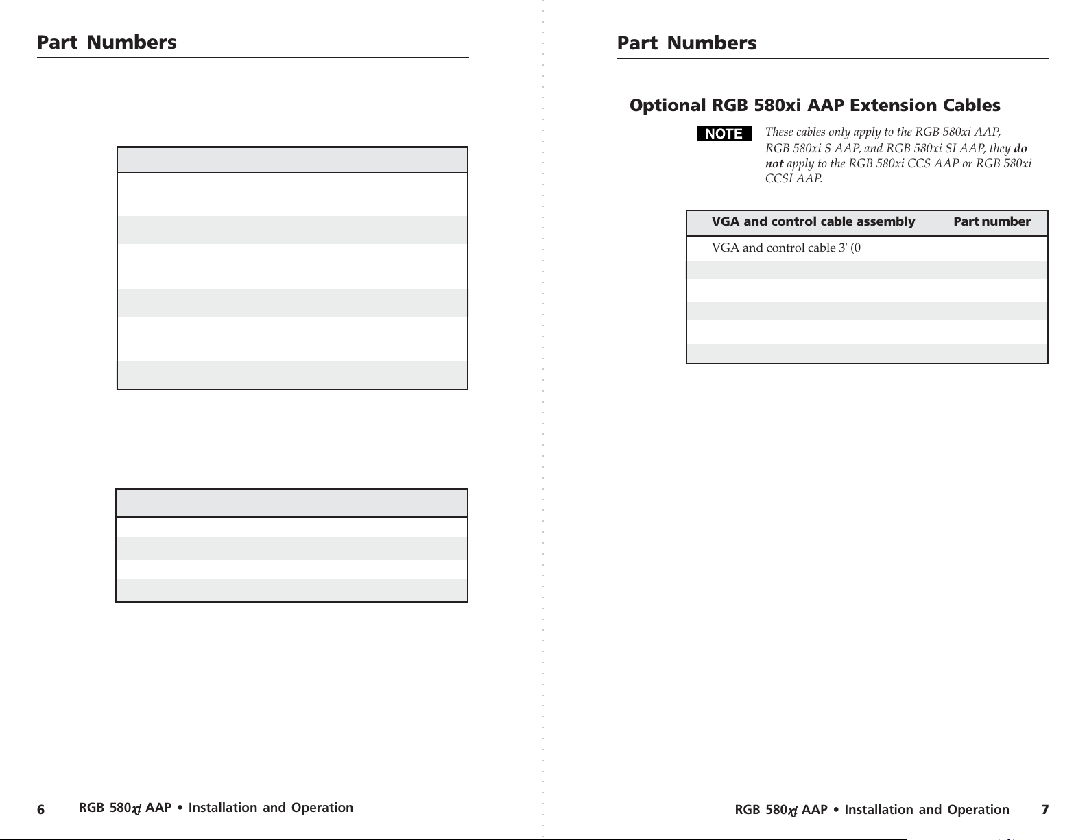
Optional RGB 580xi AAP Extension Cables
These cables only apply to the RGB 580xi AAP,
RGB 580xi S AAP, and RGB 580xi SI AAP, they do
not apply to the RGB 580xi CCS AAP or RGB 580xi
CCSI AAP.
VGA and control cable assembly Part number
VGA and control cable 3' (0.9 m) 26-521-01
VGA and control cable 6' (1.8 m) 26-521-02
VGA and control cable 12' (3.6 m) 26-521-03
VGA and control cable 25' (7.6 m) 26-521-04
VGA and control cable 35' (10.6 m) 26-521-05
VGA and control cable 50' (15.2 m) 26-521-06
RGB 580
RGB 580xi CCS AAP 9' (black) 70-254-02
RGB 580xi CCS AAP 12'
(black) 70-255-02
RGB 580xi CCSI AAP 9' (black) 70-256-02
RGB 580xi CCSI AAP 12' (black) 70-257-02
xixi
xi AAP • Installation and Operation
xixi
RGB 580
xixi
xi AAP • Installation and Operation
xixi
76
 Loading...