

Page 1
Product Category
TLP 710MV and TLP 710TV • Setup Guide
IMPORTANT:
Refer to www.extron.com for
the complete TLP 710 Series
user guide before connecting
the product to the power source.
Overview
The Extron TLP 710MV (wall-mounted) and TLP 710TV (desk-mounted) TouchLink™ Panels provide simple and versatile
configuration and control for a range of IP Link® control systems. Graphic and text objects are displayed on the screen.
These objects have system control functions associated with them, and the touch overlay allows you to activate or regulate
those functions.
These touchpanels communicate through an Ethernet connection to a configurable IP Link control processor. Video and
audio input is provided by a twisted pair cable connected to an Extron MTP transmitter.
NOTE: The network output must be connected to a network switch, hub, or router that is connected to an Ethernet
LAN or the Internet. An Extron IP Link controller must also be connected to the same network. Suggested
models include IPL T S series (for example, IPL T S4), IPL 250, IPL T CR48, IPL T SFI244, or IPCP 505.
Extron strongly recommends that power is provided by a Power over Ethernet (PoE) power supply.
This guide provides basic instructions for experienced installers to mount and perform initial configuration on the
TLP 710 series of touchpanels. Full instructions and reference material can be found in the TLP 710MV and TLP 710TV User
Guide, which is available on the Extron website (www.extron.com).
Front Panel Features
g
d
g
d
e
e
a
b
c
Extron
f
a
b
Extron
f
c
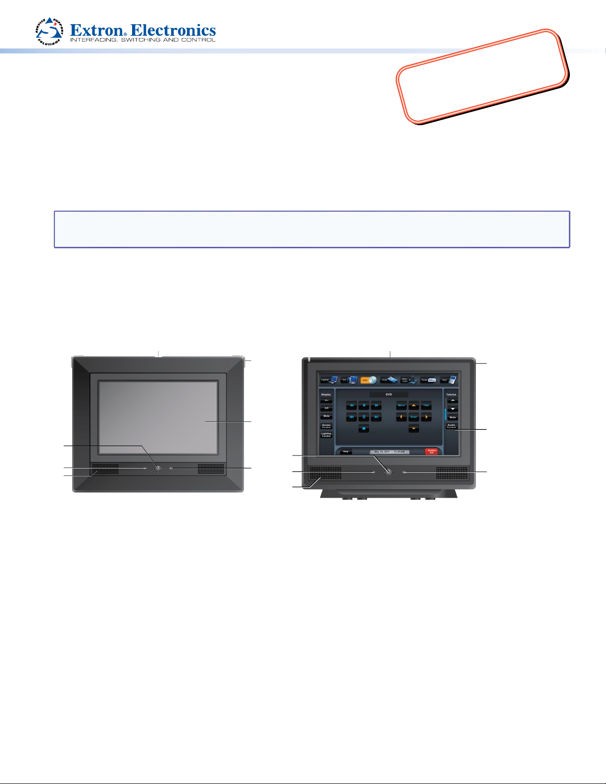
Extron TLP 710MV
Motion Sensor — when no motion has been detected for a user-defined period of time, the unit goes into sleep
a
mode. When motion is detected by the sensor, the screen display is restored and active.
Microphone — is located below the LCD screen.
b
Speaker — one, placed under the screen, on the left side of the panel, provides audible feedback for the user.
c
Programmable LEDs — one on each top corner can be programmed to provide system feedback. They light red or
d
green and can blink or light steadily.
LCD screen — has a 800x480 resolution with a touch overlay. Extron software is used to design and configure a graphic
e
user interface to display buttons, text, or icons, which have user-defined functions associated with them.
Connection status LED — is unlit during normal operation. The LED blinks red if the connection to the IP Link
f
controller is lost.
Light Sensor — (can be seen only from above the unit) monitors ambient light level and adjusts screen brightness.
g
Extron TLP 710TV
1
Page 2
TLP 710MV and TLP 710TV • Setup Guide (Continued)
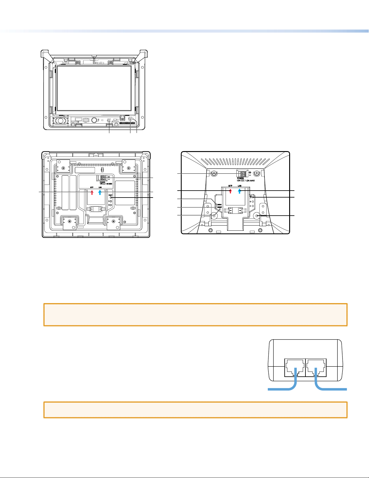
l
Power over Ethernet (PoE) Power Supply
TLP 710MV Reset Buttons and LED
Use the Extron removal tool to separate the front bezel from the
TLP 710MV. Insert the tool into one of the slots found on the bottom
surface of the unit.
Menu button — activates the on-screen menus for calibrating
h
the unit (see page 3).
Reset button — allows the unit to be reset in any of four
i
different modes (see “Reset Modes” on page 4).
Reset LED — provides feedback about the reset status when the
j
user presses the reset button (see “Reset Modes” on page 4).
Extron TLP 710MV
Rear Panel Features
Extron
Extron TLP 710MV Extron TLP 710TV
(Menu button), i (Reset button), and j (Reset LED) — see “TLP 710MV Reset Buttons and LED“ above.
h
MTP Signal Adjustments — three MTP signal adjustments are available for S-video luminance gain (VID/Y), S-video
k
chrominance gain (C), and sharpness (S). For composite video signals, the gain is controlled by the VID/Y adjustment.
Insert a small Phillips head screwdriver into the recess and turn clockwise (to increase adjustment) or counterclockwise
(to decrease).
MTP Input (optional) — a twisted pair cable, terminated with an RJ-45 connector, provides video and audio input
l
from an Extron MTP transmitter. The MTP port is in the top surface of the recessed area, (see the arrow to the left).
CAUTION: Ensure the MTP cable is connected to the MTP input and the network cable is connected to the
Network input. The voltages carried by the cables are different and connecting the MTP cable to the
Network input will damage the touchpanel unit.
h ij
n
m
k
n
l
h
i
j
m
k
o
Network and Power over Ethernet Connector — a twisted pair cable, terminated
m
with an RJ-45 connector, provides network connection. The LAN port is in the top
surface of the recessed area, (see the arrow to the right).
Extron recommends using the Power over Ethernet (PoE) power supply (provided).
Use straight-through cables to connect the LAN-IN port to a network switch and the
PWR LAN-OUT port to the LAN port of the touchpanel (see the figure to the right).
Connect the IEC power cord to a convenient 100 to 240 VAC, 50-60 Hz power source.
An Extron IP Link control interface must also be connected to the same network
domain as the TouchLink Panel. See the note on page 1 for a list of suggested models.
CAUTION: Do not connect any power supply before reading the cautions about power supplies in the “Panel
2
Power connector (optional) — Extron recommends using the PoE power supply (provided). Alternatively, you may
n
connect the 2-pole, 3.5 mm captive screw connector from a 12 VDC, 1.0 A power supply (not provided) to the power
supply socket on the rear panel.
VESA mounting holes (TLP 710TV only) — for use with the Extron LPVM-1 (part number 60-1099-02). For complete
o
mounting options for both the TLP 710MV and the TLP 710TV, see the TLP 710MV and TLP 710TV User Guide.
PWR LAN-OUT LAN-IN
To Network SwitchTo TLP 710
Features” section of the TLP 710MV and TLP 710TV User Guide.
Page 3

Product Category
Initial Conguration
Before use, configure the touchpanel, using the on-screen menus.
1. Press the Menu button once. (See “Menu button” under “TLP 710MV Reset Buttons and LED“ for the TLP 710MV or
“Rear Panel Features“ for the TLP 710TV.) The Main menu screen opens (see figure at right).
2. Press an on-screen button to highlight and select an option (the button turns green with a yellow border).
3. Use the Up and Down buttons to adjust the value. Some options have a single button and toggle between Off and On
when the button is pressed.
There are five different screens (Main, Volume, Time, Network, and Video) that
can be selected by pressing the appropriate button at the left side of the
screen. There is also an Exit button at the bottom left corner of the screen for
saving changes and leaving the menus.
Use the screens to adjust the following options (for more information, see the
TLP 710MV and TLP 710TV User Guide).
Main
Volume
Time
Network
Video
Main — adjusts the Sleep timer, Backlight, Auto Backlight, and Wake on
Motion functions. The screen also provides information about the PoE status.
Exit
Volume — adjusts the Master, Click, Sounds, and Line In volume settings.
Time — sets the correct time and date.
Network — sets the IP address and the subnet mask, and enables or disables Dynamic Host Configuration Protocol.
Video — provides a small video preview window and the controls to adjust the video contrast, color, brightness, and tint.
Sleep timer: 300 Sec
Down Up
Backlight: 073%
Down Up
Auto Backlight
Wake on Motion
PoE
On
On
Active
Calibration Menu
1. Press the Menu button a second time to open the calibration-screen (see
“TLP 710MV Reset Buttons and LED“ for the TLP 710MV or “Rear Panel
Features“ for the TLP 710TV). The on-screen button in the top left corner is
highlighted.
2. Press and hold the highlighted button until it turns gray and a new button
is highlighted. Repeat until all four points have been calibrated. The screen
reopens to the Main Screen.
3. Press Exit to close the on-screen menus.
4. (TLP 710MV) if necessary, reattach the faceplate.
Mounting Options
TLP 710MV
z Wall mounting — using the Extron BB 710M back box (part number 70-971-01) or the Extron EWB 710 wall box (part
numbers 70-969-02 [black] or 70-969-03 [white]), any of which must be purchased separately. Follow the instructions
provided with the kit. The unit may also be mounted directly to the wall without a kit, as described on page 4.
z Furniture mounting — as described on page 4.
z Rack mounting — using the RM 710M kit (part number 70-970-01), which must be purchased separately. Follow the
instructions in the user guide provided with the kit.
TLP 710TV
z Desktop mounting — by standing the unit on a suitable surface. For added security, the unit may be attached to the
desktop, using two screws, as described in the TLP 710MV and TLP 710TV User Guide.
The TLP 710TV can also be mounted using the Extron SMA-1 Swivel-Mount Adapter (part number 70-747-01), which
must be purchased separately. Follow the instructions provided with the kit and the TLP 710MV and TLP 710TV User
Guide.
z VESA mounting — using the D-type (75 x 75 mm) mounting pattern. The Extron LPVM-1 kit (part number 60-1099-02)
is optional and must be purchased separately. Follow the instructions provided with the kit. To VESA-mount the
TLP 710TV, the base must be removed from the unit, as described in the TLP 710MV and TLP 710TV User Guide.
++
Press and Hold
Highlighted Box
Until Color Changes
+
+
3
Page 4

TLP 710MV and TLP 710TV • Setup Guide (Continued)
Wall-Mounting or Furniture-Mounting the TLP 710MV
To mount the TLP 710MV directly into a wall, follow
these steps. The steps will be similar if the unit is
mounted in furniture (such as a podium or table).
1. Use the template provided to mark the wall
at a suitable location and cut a hole 7.5 inches
(19.05 cm) wide x 5.81 inches (14.76 cm) high.
2. Unpack the TLP 710MV and remove the faceplate.
3. Ensure all the locking arms are flush with the unit
and that the TLP 710MV can fit into the hole. If
necessary, use a rasp or a coarse file to enlarge the
hole.
4. Run the network and MTP cables inside the wall
to the hole, leaving enough slack in the cables to
connect them to the back of the TLP 710MV.
5. Plug the cables into the rear panel connectors (see
page 2).
z Connect the LAN port to the PoE power supply and network.
z Connect the RJ-45 MTP input.
z Optional: Extron recommends using the Power over Ethernet power supply provided. However, you may use the
LAN port only as a network connection and connect a 12 VDC, 1.0 A power supply (not provided) to the 2-pole
captive screw power input connector.
6. Push excess cables into the wall cavity.
7. Ensure the four locking arms (two at the top and two at the bottom) are flush with the top and bottom of the
TLP 710MV and fit the touchpanel into the hole.
8. Use a Phillips head screwdriver to tighten the screws for the locking arms. As the screws tighten, the locking arms rotate
behind the wall and hold the unit in place. Do not overtighten the screws as this can damage the catches or the wall.
9. If required, perform the initial configuration (see page 3).
10. Replace the faceplate by pressing the catches on the faceplate into the corresponding holes on the front of the panel.
Faceplate snaps to unit
(2 tabs on each side).
Tighten screws to
rotate locking arms.
Reset Modes
The touchpanels have four reset modes: Factory Firmware mode, Run or Stop Events mode, Reset All IP Settings mode, and
Reset to Factory Defaults mode. These modes can be initiated by pressing the reset button (see “TLP 710MV Reset Buttons
and LED“ for the TLP 710MV or “Rear Panel Features“ for the TLP 710TV). For full information about these different modes,
see the TLP 710MV and TLP 710TV User Guide.
Screen Design and Conguration
Use Extron GUI Configurator (version 1.3 or later) to design the graphical user interface that will appear on the TouchLink
panel. Use Extron Global Configurator (version 3.3 or later) to assign functions to the elements of the graphical user
interface. For complete information about these software programs, see the help file of the appropriate program.
Extron USA - West
Headquarters
+800.633.9876
Inside USA/Canada Only
+1.714.491.1500
+1.714.491.1517 FAX
4
Extron USA - East
+800.633.9876
Inside USA/Canada Only
+1.919.863.1794
+1.919.863.1797 FAX
Extron Europe
+800.3987.6673
Inside Europe Only
+31.33.453.4040
+31.33.453.4050 FAX
Extron Asia
+800.7339.8766
Inside Asia Only
+65.6383.4400
+65.6383.4664 FAX
Extron Japan
+81.3.3511.7655
+81.3.3511.7656 FAX
© 2011 Extron Electronics All rights reserved. www.extron.com
Extron China
+400.883.1568
Inside China Only
+86.21.3760.1568
+86.21.3760.1566 FAX
Extron Middle East
+971.4.2991800
+971.4.2991880 FAX
68-2028-50 Rev. A
09 11
 Loading...