

Page 1
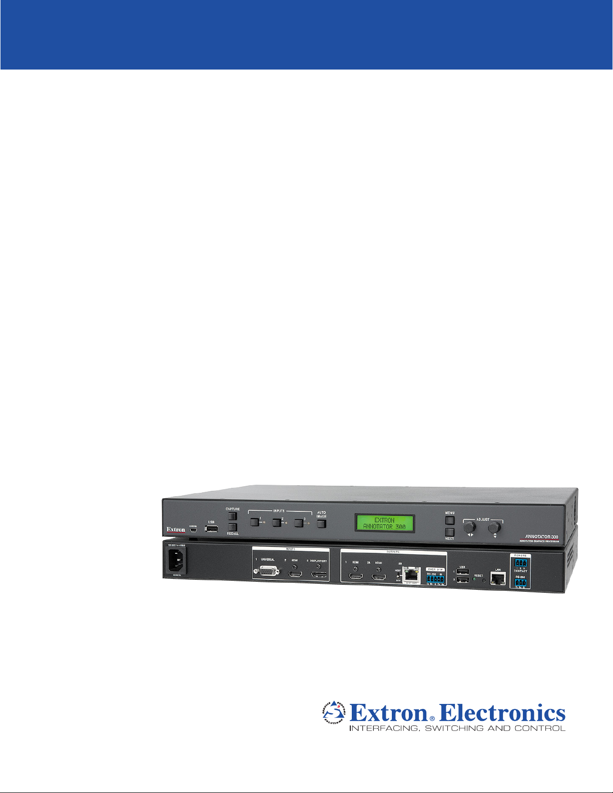
Annotator 300
HDCP-Compliant Annotation Graphics Processor
User Guide
Signal Processors
68-2378-01 Rev. A
08 14
Page 2
Precautions
Safety Instructions
Safety Instructions • English
WARNING: This symbol, , when used on the product, is intended to
alert the user of the presence of uninsulated dangerous voltage within the
product’s enclosure that may present a risk of electric shock.
ATTENTION: This symbol, , when used on the product, is intended
to alert the user of important operating and maintenance (servicing)
instructions in the literature provided with the equipment.
For information on safety guidelines, regulatory compliances, EMI/EMF
compatibility, accessibility, and related topics, see the Extron Safety and
Regulatory Compliance Guide, part number 68-290-01, on the Extron website,
www.extron.com.
Instructions de sécurité • Français
AVERTISSEMENT : Ce pictogramme, , lorsqu’il est utilisé sur le
produit, signale à l’utilisateur la présence à l’intérieur du boîtier du produit
d’une tension électrique dangereuse susceptible de provoquer un choc
électrique.
ATTENTION : Ce pictogramme, , lorsqu’il est utilisé sur le produit,
signale à l’utilisateur des instructions d’utilisation ou de maintenance
importantes qui se trouvent dans la documentation fournie avec le
matériel.
Pour en savoir plus sur les règles de sécurité, la conformité à la réglementation,
la compatibilité EMI/EMF, l’accessibilité, et autres sujets connexes, lisez les
informations de sécurité et de conformité Extron, réf. 68-290-01, sur le site
Extron, www.extron.com.
Sicherheitsanweisungen • Deutsch
WARNUNG: Dieses Symbol auf dem Produkt soll den Benutzer
darauf aufmerksam machen, dass im Inneren des Gehäuses dieses
Produktes gefährliche Spannungen herrschen, die nicht isoliert sind
und die einen elektrischen Schlag verursachen können.
VORSICHT: Dieses Symbol auf dem Produkt soll dem Benutzer in der
im Lieferumfang enthaltenen Dokumentation besonders wichtige Hinweise
zur Bedienung und Wartung (Instandhaltung) geben.
Weitere Informationen über die Sicherheitsrichtlinien, Produkthandhabung,
EMI/EMF-Kompatibilität, Zugänglichkeit und verwandte Themen finden Sie in
den Extron-Richtlinien für Sicherheit und Handhabung (Artikelnummer
68-290-01) auf der Extron-Website, www.extron.com.
Инструкция по технике безопасности • Русский
ПРЕДУПРЕЖДЕНИЕ: Данный символ, , если указан
на продукте, предупреждает пользователя о наличии
неизолированного опасного напряжения внутри корпуса
продукта, которое может привести к поражению
электрическим током.
ВНИМАНИЕ: Данный символ, , если указан на продукте,
предупреждает пользователя о наличии важных инструкций
по эксплуатации и обслуживанию в руководстве,
прилагаемом к данному оборудованию.
Для получения информации о правилах техники безопасности,
соблюдении нормативных требований, электромагнитной
совместимости (ЭМП/ЭДС), возможности доступа и других
вопросах см. руководство по безопасности и соблюдению
нормативных требований Extron на сайте Extron: www.extron.com,
номер по каталогу - 68-290-01.
Chinese Simplified(简体中文)
警告: 产品上的这个标志意在警告用户该产品机壳内有暴露的危险 电压,
有触电危险。
注意: 产品上的这个标志意在提示用户设备随附的用户手册中有
重要的操作和维护(维修)说明。
关于我们产品的安全指南、遵循的规范、EMI/EMF 的兼容性、无障碍
使用的特性等相关内容,敬请访问 Extron 网站 www.extron.com,参见
Extron 安全规范指南,产品编号 68-290-01。
Chinese Traditional( )
警告: 若產品上使用此符號,是為了提醒使用者,產品機殼內存在著
可能會導致觸電之風險的未絕緣危險電壓。
注意 若產品上使用此符號,是為了提醒使用者,設備隨附的用戶手冊中有重
要 的 操 作 和 維 護( 維 修 )説 明。
有關安全性指導方針、法規遵守、EMI/EMF 相容性、存取範圍和相關主題的詳細資
訊,請瀏覽 Extron 網站:www.extron.com,然後參閱《Extron 安全性與法規
遵守手冊》,準則編號 68-290-01。
Instrucciones de seguridad • Español
ADVERTENCIA: Este símbolo, , cuando se utiliza en el producto,
avisa al usuario de la presencia de voltaje peligroso sin aislar dentro del
producto, lo que puede representar un riesgo de descarga eléctrica.
ATENCIÓN: Este símbolo, , cuando se utiliza en el producto, avisa
al usuario de la presencia de importantes instrucciones de uso y
mantenimiento recogidas en la documentación proporcionada con el
equipo.
Para obtener información sobre directrices de seguridad, cumplimiento
de normativas, compatibilidad electromagnética, accesibilidad y temas
relacionados, consulte la Guía de cumplimiento de normativas y seguridad de
Extron, referencia 68-290-01, en el sitio Web de Extron, www.extron.com.
Japanese
警告: この記号 が製品上に表示されている場合は、筐体内に絶縁されて
いない高電圧が流れ、感電の危険があることを示しています。
注意: この記号 が製品上に表示されている場合は、本機の取扱説明書
に 記載さ れて いる重 要な操 作 と保 守 ( 整 備)の 指 示につ いてユーザ ー の 注
意を喚起するものです。
安全上のご注意、法規厳守、EMI/EMF適合性、その他の関連項目に
つ い て は 、エ ク スト ロン の ウ ェ ブ サ イト www.extron.com よ り 『 Extron Safety
and Regulatory Compliance Guide』 ( P/N 68-290-01) をご覧ください。
Korean
경고: 이 기호 가 제품에 사용될 경우, 제품의 인클로저 내에 있는
접지되지 않은 위험한 전류로 인해 사용자가 감전될 위험이 있음을
경고합니다.
주의: 이 기호 가 제품에 사용될 경우, 장비와 함께 제공된 책자에 나와
있는 주요 운영 및 유지보수(정비) 지침을 경고합니다.
안전 가이드라인, 규제 준수, EMI/EMF 호환성, 접근성, 그리고 관련 항목에
대한 자세한 내용은 Extron 웹 사이트(www.extron.com)의 Extron 안전 및
규제 준수 안내서, 68-290-01 조항을 참조하십시오.
i
Page 3

FCC Class A Notice
This equipment has been tested and found to comply with the limits for a Class A digital device,
pursuant to part15 of the FCC rules. The ClassA limits provide reasonable protection against harmful
interference when the equipment is operated in a commercial environment. This equipment generates,
uses, and can radiate radio frequency energy and, if not installed and used in accordance with the
instruction manual, may cause harmful interference to radio communications. Operation of this
equipment in a residential area is likely to cause interference. This interference must be corrected at
the expense of the user.
NOTE: For more information on safety guidelines, regulatory compliances, EMI/EMF compatibility,
accessibility, and related topics, see the “Extron Safety and Regulatory Compliance
Guide” on the Extron website.
Copyright
© 2014 Extron Electronics. All rights reserved.
Trademarks
All trademarks mentioned in this guide are the properties of their respective owners.
The following registered trademarks®, registered service marks
(SM)
, and trademarks
(TM)
are the property of
RGBSystems, Inc. or Extron Electronics:
Registered Trademarks
AVTrac, Cable Cubby, CrossPoint, eBUS, EDID Manager, EDID Minder, Extron, Flat Field, GlobalViewer, Hideaway, Inline, IPIntercom,
IPLink, Key Minder, LockIt, MediaLink, PlenumVault, PoleVault, PowerCage, PURE3, Quantum, SoundField, SpeedMount, SpeedSwitch,
SystemINTEGRATOR, TeamWork, TouchLink, V-Lock, VersaTools, VN-Matrix, VoiceLift, WallVault, WindoWall, XTP, and XTPSystems
Registered Service Mark
AAP, AFL (Accu-Rate Frame Lock), ADSP (Advanced Digital Sync Processing), Auto-Image, CableCover, CDRS (Class D Ripple Suppression),
DDSP (Digital Display Sync Processing), DMI (Dynamic Motion Interpolation), DriverConfigurator, DSPConfigurator, DSVP (Digital Sync
Validation Processing), EQIP, FastBite, FOXBOX, Global Configurator, IP Intercom HelpDesk, Link License, MAAP, MicroDigital, ProDSP, QSFPC (QuickSwitch Front Panel Controller), Scope-Trigger, SIS, Simple Instruction Set, Skew-Free, SpeedNav, Triple-Action Switching, XTRA,
ZipCaddy, ZipClip
(SM)
: S3 Service Support Solutions
Trademarks (™
(®)
)
ii
Page 4

Conventions Used in this Guide
Notifications
The following notifications are used in this guide:
CAUTION: Risk of minor personal injury.
ATTENTION : Risque de blessuremineure.
ATTENTION :
• Risk of property damage.
• Risque de dommages matériels.
NOTE: A note draws attention to important information.
Software Commands
Commands are written in the fonts shown here:
^AR Merge Scene,,Op1 scene 1,1 ^B 51 ^W^C
[01] R 0004 00300 00400 00800 00600 [02] 35 [17] [03]
E X! *X1&* X2)* X2#* X2! CE}
NOTE: For commands and examples of computer or device responses mentioned
in this guide, the character “0” is used for the number zero and “O” is the capital
letter “o.”
Computer responses and directory paths that do not have variables are written in the font
shown here:
Reply from 208.132.180.48: bytes=32 times=2ms TTL=32
C:\Program Files\Extron
Variables are written in slanted form as shown here:
ping xxx.xxx.xxx.xxx —t
SOH R Data STX Command ETB ETX
Selectable items, such as menu names, menu options, buttons, tabs, and field names are
written in the font shown here:
From the File menu, select New.
Click the OK button.
Specifications Availability
Product specifications are available on the Extron website, www.extron.com.
iii
Page 5

Contents
Introduction ....................................................1
About this User Guide ..................................... 1
About the Annotator 300 ................................. 1
Features .......................................................... 2
Installation ...................................................... 6
UL/Safety Requirements .................................. 6
Important Safety Instructions ....................... 6
Mounting the Annotator 300 ............................ 7
Tabletop Placement ..................................... 7
UL Guidelines for Rack Mounted Devices ... 7
Rack Mounting ............................................ 7
Rear Panel Features and Connections ........8
Rear Panel Features ........................................ 8
Power and Video Input Connections ............ 8
Output, User Interface, and Control
Connections ............................................... 9
Installation and Cabling .............................. 10
Powering Up ............................................. 11
Resetting the Unit with the Reset Button ....... 12
Operation ..................................................... 14
Front Panel Overview ..................................... 14
The Annotator 300 Menu System .................. 15
Overview of Menus .................................... 15
Using the Menus........................................ 17
User Presets .............................................. 17
Input Configuration .................................... 18
Output Configuration ................................. 19
Advanced Configuration ............................ 20
View Comm Settings ................................. 21
Edit Comm Settings ................................... 21
Exit Menu .................................................. 21
Capture/Recall Settings
(front panel activated) ............................... 22
Setting the Front Panel Locks
(Executive Modes) ........................................ 24
Enabling or Disabling Executive Mode
2 from the Front Panel .............................. 24
On Screen Annotation ................................. 25
Touch Panel Configuration ............................. 25
USB Port Connections .................................. 26
Touchscreen Calibration ................................ 26
Annotation Overview ...................................... 27
Default Annotation Buttons ............................ 28
SIS Communication and Control ............... 31
Front Panel Configuration Port ....................... 31
Ethernet Connection ...................................... 31
Ethernet (LAN) Port .................................... 31
Ethernet Cabling ........................................ 31
Default IP Addresses ................................. 31
Establishing a Connection.......................... 32
Connection Time-outs ............................... 32
Number of Connections ............................. 32
Using Verbose Mode ................................. 32
Host-to-Processor Instructions ...................... 32
Processor-Initiated Messages ........................ 33
Processor Error Responses ....................... 33
Using the Command/Response Table
for SIS Commands ....................................... 34
Symbol Definitions ..................................... 34
Command/Response Table for
SIS Commands ........................................ 42
Using the Command/Response Table
for IP SIS Commands ................................... 57
Symbol Definitions ..................................... 57
Command/Response Table for
IP SIS Commands .................................... 60
Product
Configuration Software ............................... 63
Installing the Software .................................... 63
Starting the Software ..................................... 64
Device Discovery Panel .............................. 64
TCP/IP Panel ............................................. 65
Offline Device Preview ................................ 66
Using the Software ........................................ 67
Device Menu.............................................. 68
Software Menu .......................................... 72
AV Controls Panel .......................................... 74
Configuration Pages ...................................... 76
Annotator 300 • Contents iv
Page 6

Input and Output Configuration Page ......... 76
EDID Minder Page ..................................... 79
Image Settings Page.................................. 81
Signal Sampling panel ............................... 81
Size and Position Page .............................. 84
Annotations Settings Page ......................... 85
OSD Settings Page .................................... 88
General Settings Page ............................... 90
Accessing the Web Page ............................... 92
Accessing the Default Web Page ................... 92
Navigating the Default Web Page .................. 93
Communication Settings ............................ 93
Input/Output Status ................................... 94
Date and Time ........................................... 95
Configure This Device ................................ 96
Device Info ................................................. 96
Passwords................................................. 97
Ethernet Connection ................................... 99
Ethernet Link ................................................. 99
Ethernet Connection .................................. 99
Default Address ......................................... 99
Telnet Tips ............................................... 101
Subnetting Basics .................................... 102
Warranty ..................................................... 106
Contact Information .................................. 106
Annotator 300 • Contents v
Page 7
Introduction
USB
CAPTURE
RECALL
MENU
NEXT
INPUTS
1
2
3
AUTO
IMAGE
ADJUST
CONFIG
Camera
Extron
This section describes this guide and features of the Annotator 300, including:
• About this User Guide
• About the Annotator 300
• Features
About this User Guide
This guide contains information to install, configure, and operate the Extron
Annotator 300 HDCP-Compliant Annotation Graphics Processor with DTP Extension.
About the Annotator 300
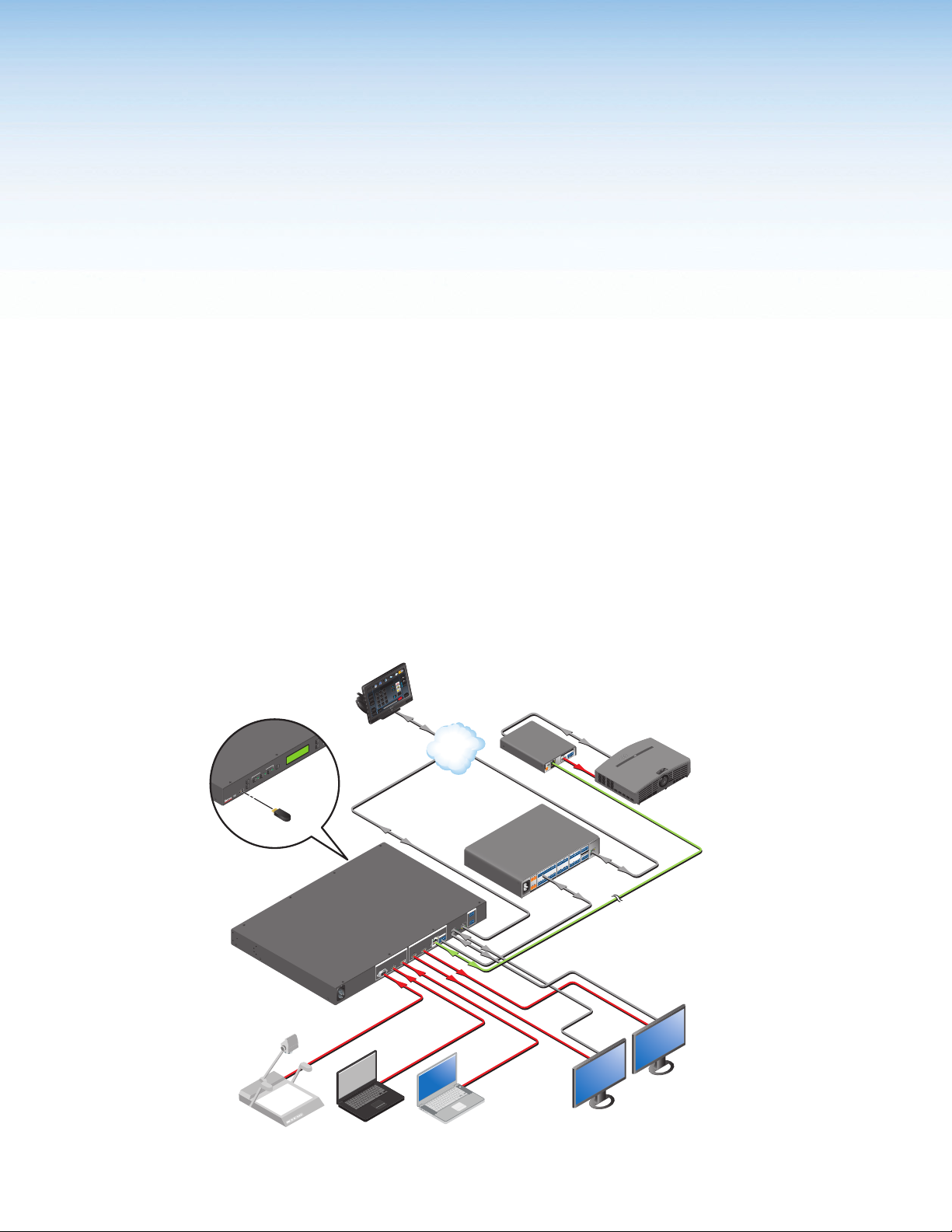
The Extron Annotator 300 is a high performance, hardware-based annotation processor
that allows a presenter to draw, point, or type over live presentations using a touch display,
graphics tablet, or a keyboard and mouse.
The HDCP-compliant Annotator 300 includes HDMI and DisplayPort inputs, a universal
analog video input, and three simultaneous outputs including two HDMI and a DTP
twisted pair output. It also features advanced Extron video signal processing with a high
performance scaling engine and fast, reliable switching. The DTP twisted pair output
extends HDMI and bidirectional control signals to a DTP receiver over a shielded twisted
pair cable up to 330 feet (100 meters). The Annotator 300 offers a wide range of annotation
tools and controls, all easily accessible by the presenter using an intuitive on-screen GUI.
Annotator 300
Front
USB Flash
Drive
Extron
Annotator 300
HDCP-Compliant
Annotation
Processor with
DTP Extension
A
--
100-240VAC
Hz
50/60
1 2 3
Tuner
Doc
Cam
Volume
VCR
TLP Pro 1020T
DVD
Presets
PC
Mute
Channel
Tuner
Laptop
10" Ta bletop TouchLink
3
2
More
6
Presets
Display
1
Audio
Last
Control
5
On
9
Pro Touchpanel
System
4
Off
Off
8
Enter
7
Mute
0
December 15, 2013 - 7:58 AM
Room
Control
Screen
Help
Lighting
Ethernet
AV Control
Network
Extron
IPCP Pro 550
IP Link Pro
Control Processor
Ethernet
REMOTE
23
1
CONTACT
RS-232
N
LA
G
Rx
Tx
ET
USB
RES
1
2
DTP
OVER
OUTPUTS
LINK
RS-232 IR
SIG
x
xR
T
G
x
TxR
HDBT
T
DTP OU
DTP
AYPORT2 3 HDMI 2A HDMI 2B
INPUTS
1 1UNIVERSAL HDMI DISPL
AX
M
100-240V ~ 50-60Hz
HDMI
R
POWE
12V
0.7A MAX
3
2
TxRx G SG
G
1
TxRx
TxRx G
2
6
G
1
TxRx
5
TxRx G RTSCTS
-
G
+
-
4
TxRx
+
COM
TOTAL
TxRx G
SWITCHED 12 VDC
4
40W MAX
G
3
TxRx
+ - + -
12 VDC
MAX
5A
HDMI
Extron
DTP HDMI 330 Rx
Receiver
RS-232
R
UDIO
A
OUTPUTS
L
NK
LI
G
I
HDMI
S
DTP IN
IPCP PRO 550
W
LAN
PWR OUT = 12
-SG
+S
+V
eBUS
1 2 3 4
1 2 3 4 G
4
8
3
I/O
FLEX
G
6 7
S
1 2
5
SG S G
7
8
RELAYSIR/SERIAL
RTSCTS
G
S
Ethernet
5 6 7
SG S G
8
SG
RS-232
USB
Projector
CATx Cable
up to 330' (100 m)
USB
VGA
HDMI
DisplayPort
Document
Figure 1. Typical Annotator 300 Application
Laptop
MacBook
Touchscreen 1
Touchscreen 2
Annotator 300 • Introduction 1
Page 8

Features
• Live annotation capabilities plus high performance scaling and switching —
The Annotator 300 allows a presenter to draw, point, or add text in real-time over live
video and graphics presentations.
• Inputs — Includes one HDMI; one DisplayPort; one universal 15-pin HD input for
RGB, component video, S-video, or composite video.
• Outputs — Includes two HDMI, one DTP twisted pair output on RJ-45
• Integrated three-input switcher with HDMI, DisplayPort, and universal analog
video inputs — The Annotator 300 delivers fast, reliable input switching between
HDMI, DisplayPort, and analog video sources. The universal auto-detecting analog
video input automatically detects incoming RGB, component video, S-video, or
composite video.
• Three simultaneous video outputs — One DTP twisted pair output and two HDMI
outputs are available for driving three displays.
• Integrated DTP output supports transmission of HDMI with embedded audio
and control up to 330 feet (100 meters) over a shielded STP cable — The DTP
output supports digital signal transmission of HDMI with embedded audio and control
up to 330 feet (100 meters) over a shielded STP cable, providing high reliability and
maximum performance on an easily installed cable infrastructure.
• Intuitive graphical annotation interface — A user-friendly on-screen display
enables quick and easy annotation. Essential annotation tools are available for
drawing freehand or lines, adding rectangular or elliptical shapes, typing text,
highlighting an area of an image, pointing to an object on-screen, and using the
screen as a whiteboard. Customization options are available for text and graphics,
including point size and color.
• Hardware-based graphics and video processing — The Annotator 300 features
a fully hardware-based system architecture designed to deliver the performance and
operational reliability essential for mission-critical applications.
• Compatible with popular touch displays and graphics tablets — The Annotator
300 supports a wide variety of touch displays and graphics tablets from third-party
manufacturers, and also can be used with a standard keyboard and mouse.
• Capture, store, and recall images — An image can be captured as a snapshot
of the live video output, including annotations, and saved to internal memory, a
removable USB flash drive, or a network location for archiving.
• Print captured images using a network printer — The Annotator 300 supports
connection to a printer on the network, enabling captured images to be sent directly
to the printer without connecting to a PC.
• Configurable Main and Confidence outputs — The outputs can be configured
as separate Main and Confidence outputs with individually controlled visibility of
annotation and OSD graphics.
• HDCP compliant — Fully supports HDCP-encrypted sources, with selectable
authorization for unencrypted content.
• Supported HDMI specification features include data rates up to 6.75 Gbps, Deep
Color, and HD lossless audio formats
• Supports DisplayPort input signals at resolutions up to 2560x1600
• Compatible with shielded twisted pair cable — The Annotator 300 fully supports
a maximum transmission distance of 330 feet (100 meters) for all compatible
resolutions when used with shielded twisted pair cable. Shielded twisted pair cabling
with solid center conductor sizes of 24 AWG or better is recommended for optimal
performance.
Annotator 300 • Introduction 2
Page 9

• Extron XTP DTP 24 shielded twisted pair cable is strongly recommended for
optimal performance
• Bidirectional RS-232 and IR pass-through for AV device control — Bidirectional
RS-232 control and IR signals can be transmitted alongside the video signal over
the DTP connection, allowing the remote device to be controlled without the need
for additional cabling. Bidirectional control extension eliminates the need for control
system wiring to remote devices.
• Remote powering of DTP receiver — The Annotator 300 can provide remote
power to a DTP receiver over the twisted pair connection, eliminating the need for a
separate power supply at the remote unit.
• Compatible with all DTP 230 and DTP 330 Series receivers, and DTP-enabled
products — Enables mixing and matching with desktop and wallplate receivers, as
well as other DTP-enabled products to meet application requirements.
• DTP output is compatible with HDBaseT-enabled devices — The DTP output
can be configured to send video and embedded audio, plus bidirectional RS-232 and
IR signals to an HDBaseT-enabled display.
• Auto-switching between inputs — Auto-switching allows for simple, unmanaged
installation in locations such as in a lectern or under a conference table. When
multiple inputs are active, the switching priority is configurable.
• Auto Input Format Detection — For the universal analog video input, the Annotator
300 detects the incoming signal format, automatically reconfiguring itself to provide
the appropriate decoding and signal processing. This feature can reduce the number
of required outputs for a matrix switcher, lowering system cost while improving
manageability.
• Selectable output rates from 640x480 to 1920x1200, including HDTV 1080p/60
and 2K — Available output rates include computer-video up to 1920x1200, HDTV
rates up to 1080p/60, and 2K.
• Advanced scaling engine with 30-bit processing and 1080i deinterlacing —
Image scaling and video format conversion are performed at 30-bit precision for
enhanced color accuracy and picture detail. High performance deinterlacing of 1080i
signals from HD sources delivers optimized image quality.
• Key Minder continuously verifies HDCP compliance for quick, reliable
switching — Key Minder authenticates and maintains continuous HDCP encryption
between input and output devices to ensure quick and reliable switching in
professional AV environments, while enabling simultaneous distribution of a single
source signal to one or more displays.
• EDID Minder automatically manages EDID communication between
connected devices — EDID Minder ensures that all sources power up properly and
reliably output content for display.
• SpeedSwitch Technology provides exceptional switching speed for HDCP-
encrypted content
• Aspect ratio control — The aspect ratio of the video output can be controlled by
selecting a FILL mode, which provides a full screen output, or a FOLLOW mode,
which preserves the original aspect ratio of the input signal.
• HDCP authentication and signal presence confirmation — Provides real-time
verification of HDCP status for each digital video input and output. This allows for
easy signal and HDCP verification through RS-232 or Ethernet, providing valuable
feedback to a system operator or helpdesk support staff.
Annotator 300 • Introduction 3
Page 10

• HDCP Visual Confirmation provides a green signal when encrypted content
is sent to a non-compliant display — A full-screen green signal is sent when
HDCP-encrypted content is transmitted to a non-HDCP compliant display, providing
immediate visual confirmation that protected content cannot be viewed on the display.
• HDMI to DVI Interface Format Correction — Automatically enables or disables
embedded audio and InfoFrames, and sets the correct color space for proper
connection to HDMI and DVI displays.
• Seamless switching — Seamless cut through black and fade through black
transition effects are available to enhance presentations by eliminating distractions
during switching.
• Auto-Image setup — When activated, the unit automatically optimizes the image
by analyzing and adjusting to the video input signal. This can save time and effort in
setting up a newly connected source, particularly in presentation environments where
different guest presenter laptops with various output resolutions will be connected.
• Auto Input Memory — When activated, the unit automatically stores size, position,
and picture settings based on the incoming signal. When the same signal is detected
again, these image settings are automatically recalled from memory.
• Output Standby Mode — The unit can be set to automatically mute video and sync
output to the display device when no active input signal is detected. This allows the
projector or flat-panel display to automatically enter into standby mode to save energy
and enhance lamp or panel life.
• Power Save Mode — The unit can be placed in a low power standby state to
conserve energy when not in use.
• AFL - Accu-RATE Frame Lock — A patented technology exclusive to Extron that
locks the output frame rate to a designated input to eliminate stuttering caused by
frame rate conversion.
• Image freeze control — A live image can be frozen using RS-232 serial control,
USB, Ethernet control, or the annotation GUI.
• Picture controls — Available for adjusting brightness, contrast, color, tint, and detail,
as well as horizontal and vertical positioning and sizing.
• Quad standard video decoding — A temporal, 3D adaptive comb filter provides
advanced decoding of composite NTSC 3.58, NTSC 4.43, PAL, and SECAM for
integration into systems worldwide.
• User presets — Memory presets are available for each input to store and recall
optimized image settings.
• Automatic 3:2 and 2:2 pulldown detection — Advanced film mode processing
techniques that help maximize image detail and sharpness for NTSC, PAL, and
HDTV 1080i sources that originated from film.
• Internal video test patterns for calibration and setup — The unit offers several
video test patterns to facilitate proper system setup and calibration of display devices.
• Integrated audio delay — Embedded audio is passed through to all outputs and
automatically delayed to compensate for latency introduced by the video processing.
• Front panel security lockout — This feature locks out all front panel functions
except for input selection; all functions however, are available through Ethernet, USB,
or RS-232 control.
• Ethernet monitoring and control — Enables control and proactive monitoring over
a LAN, WAN, or the Internet.
• Built-in Web pages — Enables the use of a standard browser for monitoring over an
intuitive Web interface.
Annotator 300 • Introduction 4
Page 11

• RS-232 control port — Enables the use of serial commands for complete control
and configuration via the Extron Windows®-based control program, or integrated into
a control system. Extron products use the SIS™ - Simple Instruction Set command
protocol, a set of basic ASCII commands that allow for quick and easy programming.
• Front panel USB configuration port — Enables easy configuration without having
to access the rear panel.
• Contact closure ports — Can be used for external control of source switching.
• RJ-45 signal and link LED indicators for DTP port — Provides a means for
validating signal flow and operation, allowing quick identification of connectivity
issues.
• Easy setup and commissioning with the Extron Product Configuration
Software (PCS) — Conveniently configure multiple products using a single software
application.
• Rack-mountable 1U, full rack width metal enclosure
• Includes LockIt HDMI cable lacing brackets
• Highly reliable, energy-efficient internal universal power supply — The
100-240 VAC, 50/60 Hz, international power supply provides worldwide power
compatibility with high demonstrated reliability.
Annotator 300 • Introduction 5
Page 12

Installation
This section contains installation information for the Extron Annotator 300. It covers the
following subjects:
• UL/Safety Requirements
• Mounting the Annotator 300
UL/Safety Requirements
The Underwriters Laboratories (UL) requirements listed below pertain to the safe
installation and operation of this Annotation Graphics Processor.
Important Safety Instructions
1. Read these instructions.
2. Keep these instructions.
3. Heed all warnings.
4. Follow all instructions.
5. Do not use this apparatus near water.
6. Clean only with a dry cloth.
7. Do not block any ventilation openings. Install in accordance with the manufacturer’s
instructions.
8. Do not install near any heat sources such as radiators, heat registers, stoves, or other
apparatus (including amplifiers) that produce heat.
9. Do not defeat the safety purpose of the polarized or grounding type plug. A polarized
plug has two blades with one wider than the other. A grounding type plug has two
blades and a third grounding prong. The wide blade or the third prong are provided
for your safety. If the provided plug does not fit into your outlet, consult an electrician
for replacement of the obsolete outlet.
10. Protect the power cord from being walked on or pinched particularly at plugs,
convenience receptacles, and the point where they exit from the apparatus.
11. Only use attachments/accessories specified by the manufacturer.
12. Use only with the cart, stand, tripod, bracket, or table specified by the manufacturer,
or sold with the apparatus. When a cart is used, use caution when moving the cart/
apparatus combination to avoid injury from tip-over.
13. Unplug this apparatus during lightning storms or when unused for long periods of
time.
14. Refer all servicing to qualified service personnel. Servicing is required when the
apparatus has been damaged in any way, such as power-supply cord or plug is
damaged, liquid has been spilled or objects have fallen into the apparatus, the
apparatus has been exposed to rain or moisture, does not operate normally, or has
been dropped.
Annotator 300 • Installation 6
Page 13

Mounting the Annotator 300
Rack Ears
If the Annotator 300 is to be rack mounted, it is important to mount it before cabling it.
Four rubber feet are included with the unit. Install the feet only if the unit is to be mounted
on a table top (see “Tabletop Placement” below).
Tabletop Placement
For tabletop placement, install the self-adhesive rubber feet/pads (provided) onto the four
corners of the bottom of the device.
UL Guidelines for Rack Mounted Devices
The following Underwriters Laboratories (UL) guidelines pertain to the safe installation of
the Annotator 300 in a rack.
1. Elevated operating ambient temperature — If installed in a closed or multi-unit rack
2. Reduced air flow — Install the equipment in a rack so that the amount of air flow
3. Mechanical loading — Mount the equipment in the rack so that a hazardous condition
4. Circuit overloading — Connect the equipment to the supply circuit and consider the
5. Reliable earthing (grounding) — Maintain reliable grounding of rack-mounted
Rack Mounting
assembly, the operating ambient temperature of the rack environment may be greater
than room ambient temperature. Therefore, install the device in an environment
compatible with the maximum ambient temperature (Tma = +122 °F, +50 °C) as
specified by Extron.
required for safe operation of the equipment is not compromised.
is not achieved due to uneven mechanical loading.
effect that circuit overloading might have on overcurrent protection and supply wiring.
Appropriate consideration of equipment nameplate ratings should be used when
addressing this concern.
equipment. Pay particular attention to supply connections other than direct
connections to the branch circuit (for example, use of power strips).
Mount the Annotator 300 to a rack using the pre-installed rack ears (see figure 2, left
image), or use an optional MBU 149 mounting kit (part number 70-222-01) for under-thedesk mounting (see figure 2, right image).
Mounting Screws
(2) Places
Each Side
#8 Screw
(4) Places
Each Side
MBU 149
Mounting Bracket
Figure 2. Mounting the Annotator 300; rack or under-desk mounting.
Annotator 300 • Installation 7
Page 14
Rear Panel Features and Connections
This section describes the rear panel features and how to connect the cables.
Rear Panel Features
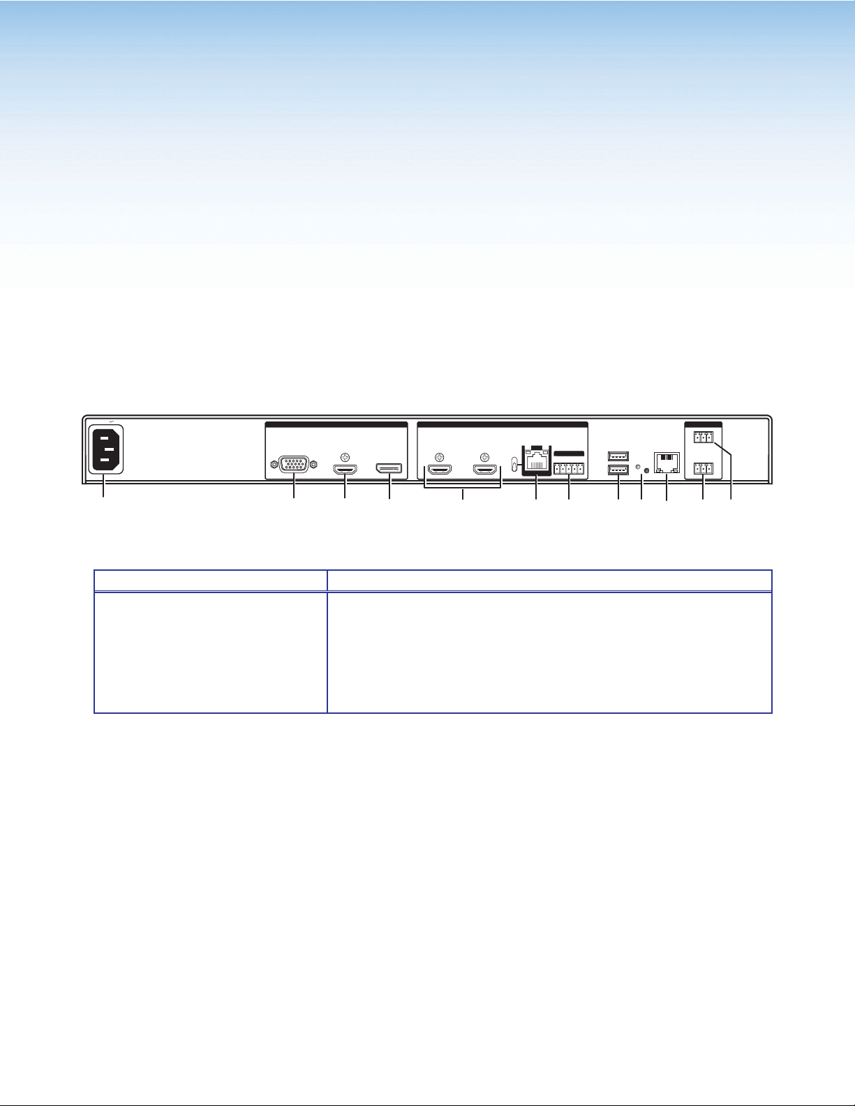
The illustration below shows the rear panel features of the Annotator 300.
100-240VAC --A MAX
50/60 Hz
A
1 1UNIVERSAL HDMI DISPLAYPORT23 HDMI 2A HDMI 2B
BC
INPUTS
D
SIG
LINK
HDBT
DTP
OVER DTP
RS-232 IR
HDBT
OUT
Tx Rx GTxRx
1
2
EFGHIJK
Figure 3. Annotator 300 Rear Panel Features
Power and video input connections Outputs and control connections
A AC power connector
B Universal analog 15-pin HD connector
C HDMI connector (HDMI/DVI inputs)
D DisplayPort connector
E HDMI connectors (2) (HDMI/DVI outputs)
F
RJ-45 connector (DTP or HDBaseT
output), selectable by switch
G
5-pole captive screw connector
(for DTP RS-232 and IR insert)
H
USB A connectors (2)
I
Reset button and LED
J
RJ-45 LAN connector
K
Remote RS-232 3-pole captive
screw connector
L
Remote contact closure 3-pole
captive screw connector
Power and Video Input Connections
A AC power connector — After connecting all input and output cables, plug a
standard IEC power cord from a 100 to 240 VAC, 50 Hz to 60 Hz power source
into this receptacle.
REMOTEOUTPUTS
1
USB
RESET
23
LAN
CONTACT
RS-232
Tx Rx G
L
Universal analog connector — Connect high resolution computer-video input
B
signals to this 15-pin HD connector.
C
HDMI connector — Connect an HDMI or DVI (with an adapter) source to this
HDMI connector.
D
DisplayPort connector — Connect a suitable DisplayPort source to this
DisplayPort connector.
Annotator 300 • Rear Panel Features and Connections 8
Page 15

Output, User Interface, and Control Connections
HDMI connectors — Connect suitable HDMI or DVI (with an adapter) displays
E
to these two connectors for HDMI or DVI output.
RJ-45 connector — Connect the Annotator 300 to a DTP receiver for selectable
F
DTP or HDBaseT output that supports the digital signal transmission of HDMI
with embedded audio and control up to 330 feet (100 meters) over shielded
twisted pair (STP) cable. Output format is selected by setting the switch
accordingly.
CAUTION: Risk of damage to equipment. DO NOT connect an HDBaseT unit if
using DTP transmission. The power carried over DTP may damage the unit.
ATTENTION: Cela risque d’endommager votre équipement. Ne PAS connecter
une unité HDBaseT si vous utilisez la transmission DTP. L’alimentation transmise
sur DTP peut endommager l’unité.
5-pole captive screw connector — Connect to this for bi-directional RS-232
G
over DTP and IR insertion.
USB A ports — Connect up to twenty touch panel devices (using USB hubs), or
H
a USB mouse and keyboard to these ports.
Reset button and LED — This button is used to reset the switcher to any one
I
of four different states. The LED indicates the status during the procedure.
Refer to the Resetting the Unit with the Reset Button” section, for details.
J
WAN via this RJ-45 connector. Ethernet control allows the operator to control the
processor from a remote location. When connected to an Ethernet LAN or WAN,
the device can be accessed and operated from a computer running a standard
Internet browser. The Link LED lights green when the Annotator 300 is connected
to an Ethernet LAN, and the Act LED flickers amber, indicating data transmission
as the devices communicate.
K
two-way RS-232 communication. Connect a host computer or control system to
this for serial RS-232 or RS-422 control. The default protocol is 9600 baud,
1 stop bit, no parity, and no flow control.
L
device to this 3-pole connector for remote contact closure control.
RJ-45 Ethernet connector — Connect the Annotator 300 to Ethernet LAN or
RS-232 3-pole captive screw connector — This connector provides for
Remote contact closure 3-pole captive screw connector — Connect a host
9Annotator 300 • Rear Panel Features and Connections
Page 16

Installation and Cabling
Step 1 — Mount the Annotator 300 device
Turn off or disconnect all equipment power sources and rack mount the device (see
page 7).
Step 2 — Connect inputs
Connect inputs from video sources to the applicable connectors marked “Inputs”
(see page 8, B to D for connector types).
Step 3 — Connect outputs
Connect video output devices to the applicable output connectors marked “Outputs”
(see page 9,
Step 4 — Connect user interface devices
Connect user interface devices (mouse and keyboard) or touch panels to the
Annotator 300 using either of the rear panel USB ports (see H on page 9).
Alternatively the front panel USB port can also be used to connect a user interface
device.
Step 5 — Connect touch panel devices
Via USB A ports — Connect a touch panel device to either port Has desired. For
most devices no configuration is needed.
Step 6 — Connect control devices
LAN Ethernet port — Connect to an Ethernet LAN or WAN via this RJ-45 connector
to control the processor from a remote location, using a PC’s Internet browser.
J
See apge 98, Ethernet Connections section for network cable termination method.
Ethernet connection indicator LEDs marked indicate the status of the Ethernet
connection. The green LED lights when connected to an Ethernet LAN, and the
amber LED flickers as the devices communicate.
Remote ports — For serial RS-232 or RS-422 control, or contact closure control,
connect a host computer or control system via the two 3-pole captive screw
connectors
• 9600 baud • 1 stop bit • no parity • 8 data bits • no flow control.
to G for connector types).
E
KandL
. RS-232 protocol (default values):
NOTE: See “SIS Communication and Control” section (page 31 onwards) for
definitions of the SIS commands and “Product Configuration Software”
section (page 63 onwards) to install and use the control software.
Step 7 — Connect power
AC power connector — Plug in a standard IEC power cord from a 100 to 240 VAC,
50 - 60 Hz power source into this receptacle A.
10Annotator 300 • Rear Panel Features and Connections
Page 17
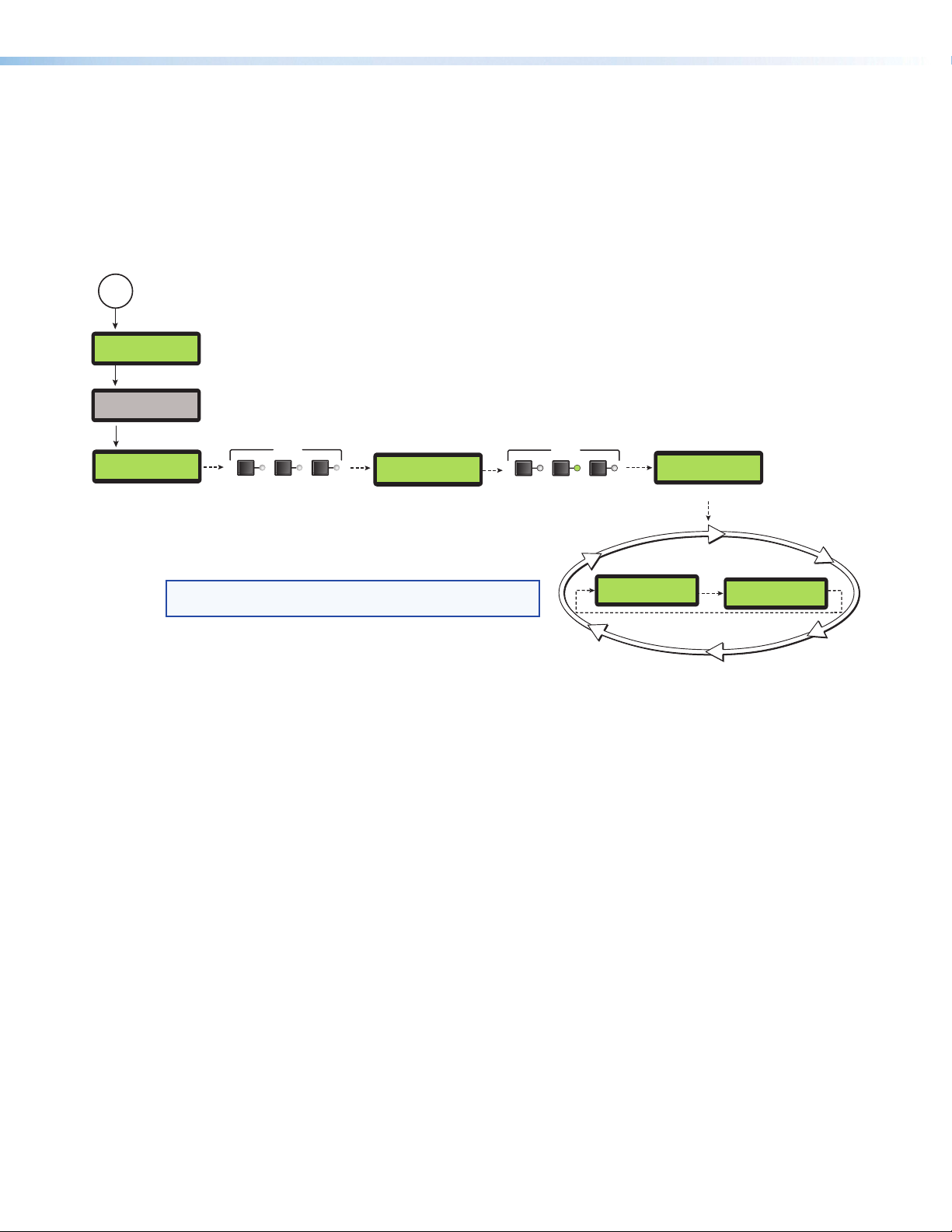
Powering Up
20
sec.
10
sec.
Apply
Power
10
sec.
LCD display lights (no text)
When applying power to the Annotator 300, the unit undergoes a start-up self testing
sequence (see image below) and then the LCD displays the default display cycle.
Default display cycle
When in use but not in any menu mode, the LCD screen defaults to cycling through the
input/output configuration currently installed. The displayed content may vary, depending
on the input video signal type. See the figure below for a typical default display cycle.
LCD display lights (no text)
LCD goes off
1
sec.
All input button LEDs momentarily
flash red, then green.
INPUTS
123
1
sec.
Extron
ANNOTATOR 300
LCD display lights (with text)
3
sec.
INPUTS
123
Last active input button LED
remains lit (green).
1
sec.
60-1316-01
FW v1.0
LCD display lights (with text)
1
sec.
Default Display Cycle
NOTE: The input and output rates shown in the default display
cycle may differ, depending on the type of video signal active.
Input #2
60.0kHz 75.0Hz
2
sec.
Output Rate
1024x768 60.0Hz
2 sec.
Figure 4. Typical Default Cycle
The default display cycle shows the output resolution and the refresh rates for the
currently selected input.
11Annotator 300 • Rear Panel Features and Connections
Page 18
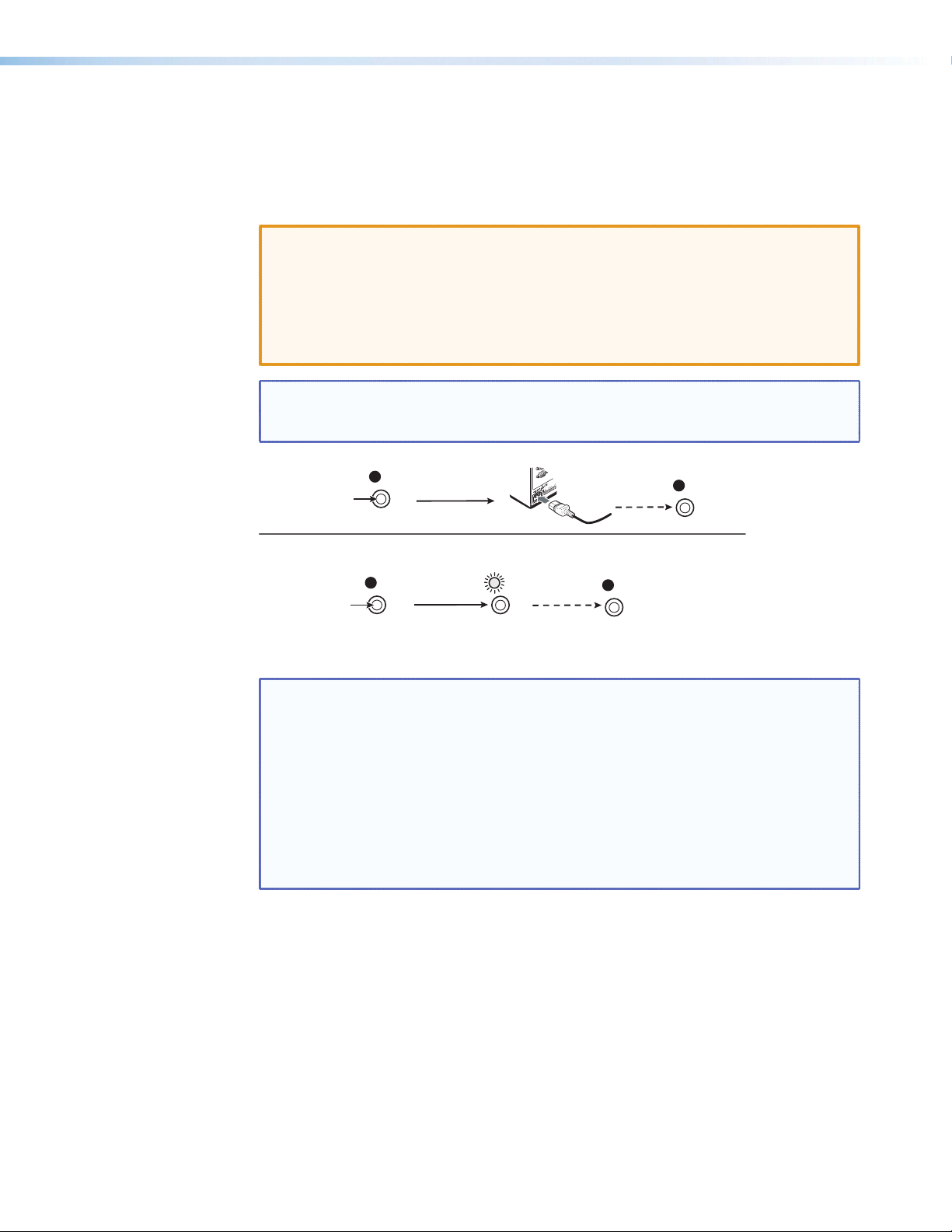
Resetting the Unit with the Reset Button
RESET
RESET
RESET
1
2
There are three reset modes (numbered 1, 4, and 5 for the sake of comparison with
Extron IPL products) that you can access by pressing the Reset button on the rear panel.
The Reset button is recessed, so use a pointed stylus, ballpoint pen, or Extron Tweeker to
press it. See the table on page 13 for a summary of the reset modes.
CAUTION: Review the reset modes carefully. Using the wrong reset mode may result
in unintended loss of flash memory programming, port reassignment, or
processor reboot.
ATTENTION: Étudier de près les différents modes de réinitialisation. Appliquer le
mauvais mode de réinitialisation peut causer une perte inattendue de la
programmation de la mémoire flash, une reconfiguration des ports ou une
réinitialisation du contrôleur.
NOTE: The reset modes listed in the table close all open IP and Telnet connections
and close all sockets. Also, each mode is a separate function, not a continuation
from mode 1 to mode 5.
Mode 1
Press and hold
the Reset button.
Modes 4, and 5
Press and hold for
6 or 9 seconds.
RESET
Reset LED flashes once,
twice, or three times.
Apply Power
Release, then immediately
press and release again. Reset
LED flashes in confirmation.
Release Reset button.
RESET
Figure 5. Resetting the Annotator 300
NOTES:
• After a mode 1 reset is performed, update the firmware for the Annotator 300
to the latest version. Do not operate the firmware version that results from the
mode 1 reset. If the factory default firmware is to be used, that version must be
uploaded again.
• If you do not want to update firmware, or you performed a mode 1 reset by
mistake, cycle power to the device to return to the firmware version that was
running before the mode 1 reset. Use the 0Q SIS command to confirm that the
factory default firmware is no longer running (look for the asterisk [*] following the
version number).
See the table on next page for a summary of the reset modes.
12Annotator 300 • Rear Panel Features and Connections
Page 19

Annotator Reset Mode Summary
Mode Activation Result Purpose/Notes
Hold down the recessed Reset button
1
while applying power to the unit
The Annotator 300 reverts to the factory
default rmware. Event scripting does
not start if the device is powered in this
mode. All user files and settings (drivers,
adjustments, IP settings) are maintained.
This mode reverts to the factory
default firmware version if
incompatibility issues arise with
user-loaded firmware.
NOTE: After a mode 1 reset is
performed, update the Annotator
300 firmware to the latest version.
Do not operate the firmware
version that results from this
mode reset. If you want to use
Use Factory Firmware
4
the factory default firmware,
you must upload that version
again. See page 71 for details on
uploading firmware.
Hold down the Reset button for about
6 sec. until the Power LED blinks twice
(once at 3 sec., again at 6 sec.). Then
release and press Reset momentarily (for
<1 sec.) within 1 second.
NOTE: Nothing happens if the
momentary press does not occur
within 1 second.
Reset all IP Settings
Hold down the Reset button for about
5
9 sec. until the Power LED blinks three
times (once at 3 sec., again at 6 sec.,
again at 9 sec.). Then release and press
Reset momentarily (for <1 sec.) within 1
second.
Defaults
Reset to Factory
NOTE: Nothing happens if the
momentary press does not occur
within 1 second.
NOTE: If you do not want to update
firmware, or you performed a mode
1 reset by mistake, cycle power to
the Annotator 300 to return to the
firmware version that was running
prior to the mode 1 reset. Use the
0Q SIS command to confirm that the
factory default firmware is no longer
running (look for asterisks following
the version number.)
This mode does the following:
• Enables ARP capability.
• Sets the IP address back to factory
default (192.168.254.254).
• Sets the subnet back to factory default.
• Sets the default gateway address to the
factory default.
• Sets port mapping back to factory
default.
• Turns DHCP off.
• Turns events off.
This mode performs a complete reset to
factory defaults (except the rmware).
• Does everything mode 4 does.
• Removes button/touchpanel
configurations.
• Resets all IP options.
• Removes scheduling settings.
• Removes/clears all files from the unit.
NOTE: User-defined web
pages may not work
correctly if using an
earlier firmware version.
This mode enables you to set IP
address information using ARP
and the MAC address.
This mode is useful if you want to
start over with configuration and
uploading, and also to replace
events.
13Annotator 300 • Rear Panel Features and Connections
Page 20
Operation
A
D
EFG
H
B
C
This section of the manual discusses the operation of an Annotator 300 unit and is divided
into four sections:
• Front Panel Overview
• The Annotator 300 Menu System
• Setting the Front Panel Locks (Executive Modes)
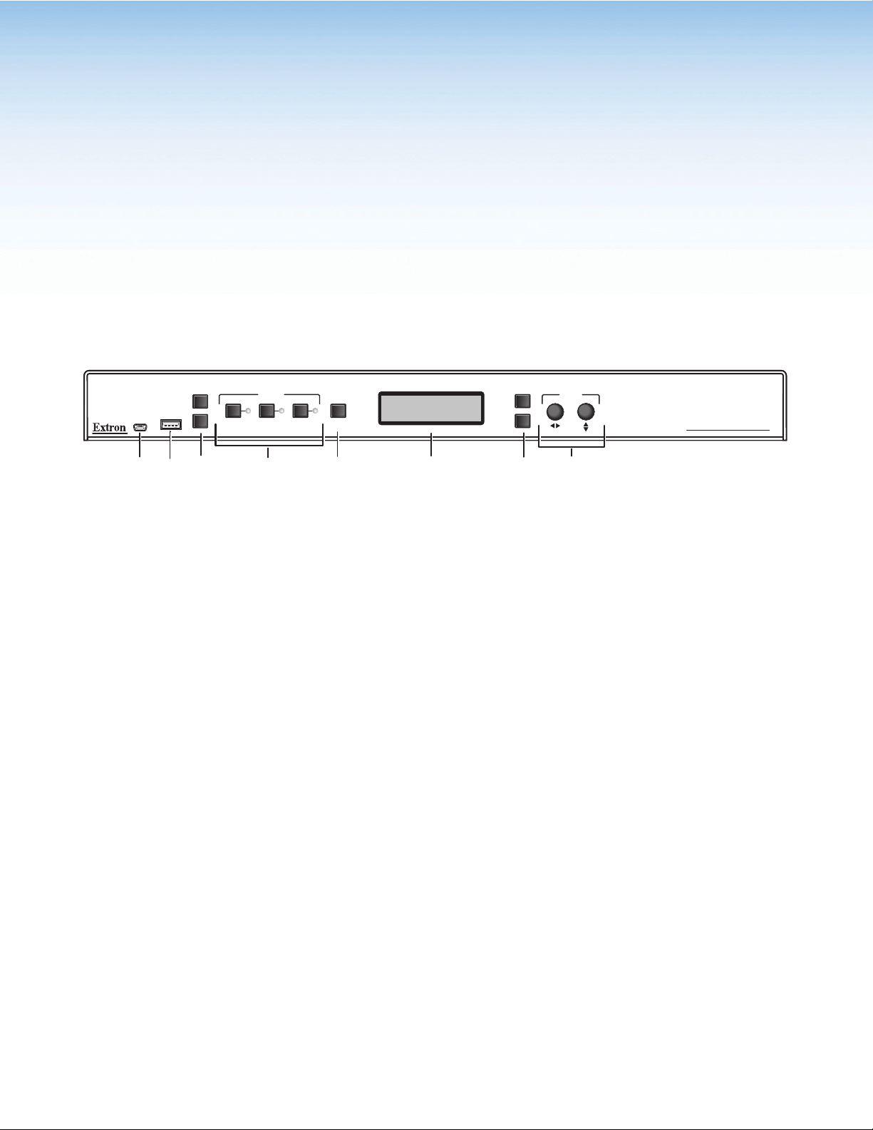
Front Panel Overview
CONFIG
CAPTURE
USB
RECALL
INPUTS
123
Figure 6. Front Panel Features
Front panel configuration port — Connect a control system or computer to
A
this mini USB port using an optional USB A Male to USB Mini B Male
Configuration Cable. This port is used for unit configuration and
firmware upgrades.
Front panel USB port — Connect an external drive to store or recall captured
B
images, or connect a user interface device to this port.
CE
• Capture — Allows the capture and saving of the current image,.
• Recall — Allows the user to recall a saved image.
• Auto Image — Initiates auto image adjustment on the selected input.
Input buttons and LEDs — These three buttons are used to select and switch
D
inputs. A lit LED indicates the currently active input.
AUTO
IMAGE
Special function buttons — These three buttons are:
MENU
NEXT
ADJUST
ANNOTATOR 300
ANNOTATION GRAPHICS PROCESSOR
LCD display — This LCD screen displays two rows of menu, control response,
F
and configuration text.
Menu navigation buttons — These two buttons give access to menu
G
commands. See “The Annotator 300 Menu System” section in this chapter.
• Menu button — This button gives direct access to a series of five menus.
• Next button — This button allows page changes within each one of the
menus, and to exit the menu cycle.
Adjustment knobs — These two knobs are used with the menu navigation
H
buttons to adjust settings.
Annotator 300 • Operation 14
Page 21
The Annotator 300 Menu System
The Annotator 300 can be configured using the menu system, via the Extron Simple
Instruction Set (SIS) of commands, or via the Extron Products Configuration Software
(PCS 2.1 or higher) software program, through an RS-232 or LAN connected PC.
NOTE: For methods see “SIS Communication and Control” and “Product
Configuration Software (PCS)” section.
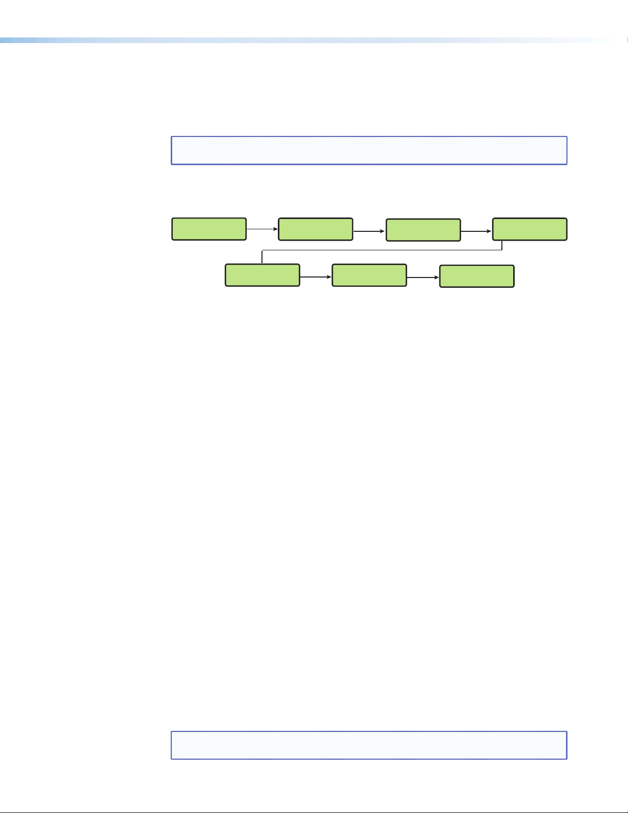
The Annotator 300 has six front panel configuration menus: User Presets, Picture Control,
Input Configuration, Output Configuration, Advanced Configuration, and View Comm
Settings. A hidden menu (Edit Comm Settings) is also accessible.
User
Presets
Menu
Picture
Control
Menu
Input
Configuration
Menu
Menu
Output
Configuration
Advanced
Configuration
Menu
View Comm
Settings
Menu
Exit Menu
Press NEXT
Figure 7. The Annotator 300 Front Panel Configuration Menus
Overview of Menus
User Presets
This menu allows the user to save the current image settings to a preset number (1-16),
and recall any saved preset to become the current image settings. Each input has sixteen
user selectable presets.
Picture Control
This menu allows configuration of the following settings for an active input:
Horizontal and vertical centering and sizing, brightness, contrast, tint, color. and detail.
Input Configuration
Output Configuration
This menu allows configuration of the following setting for any selected input:
Input type, film detection, vertical and horizontal start points, pixel phase, the number of
total and active pixels, and input EDID value (see the tables on page 18).
This menu allows configuration of the following settings for the active output:
Resolution and refresh rate (see the table on page 19), HDMI format, and HDCP note
setting.
Advanced Configuration
This menu allows advanced configuration of the following Annotator 300 settings:
Test Pattern, Calibrate Panels, Auto Image, Aspect Ratio, Auto Memory, Capture/Recall
format, Overscan setting, Switch Effect, Internal Temp (view only), and Reset to Factory
defaults.
View Comm Settings
This menu allows the user to view the following serial and IP settings for the unit:
Serial port baud rate, MAC address, DHCP (Dynamic Host Configuration Protocol) setting,
IP address, subnet mask address, and gateway address
NOTE: These settings can not be edited from within this menu. See ”Edit Comm
Settings (hidden)” on next page.
Annotator 300 • Operation 15
Page 22
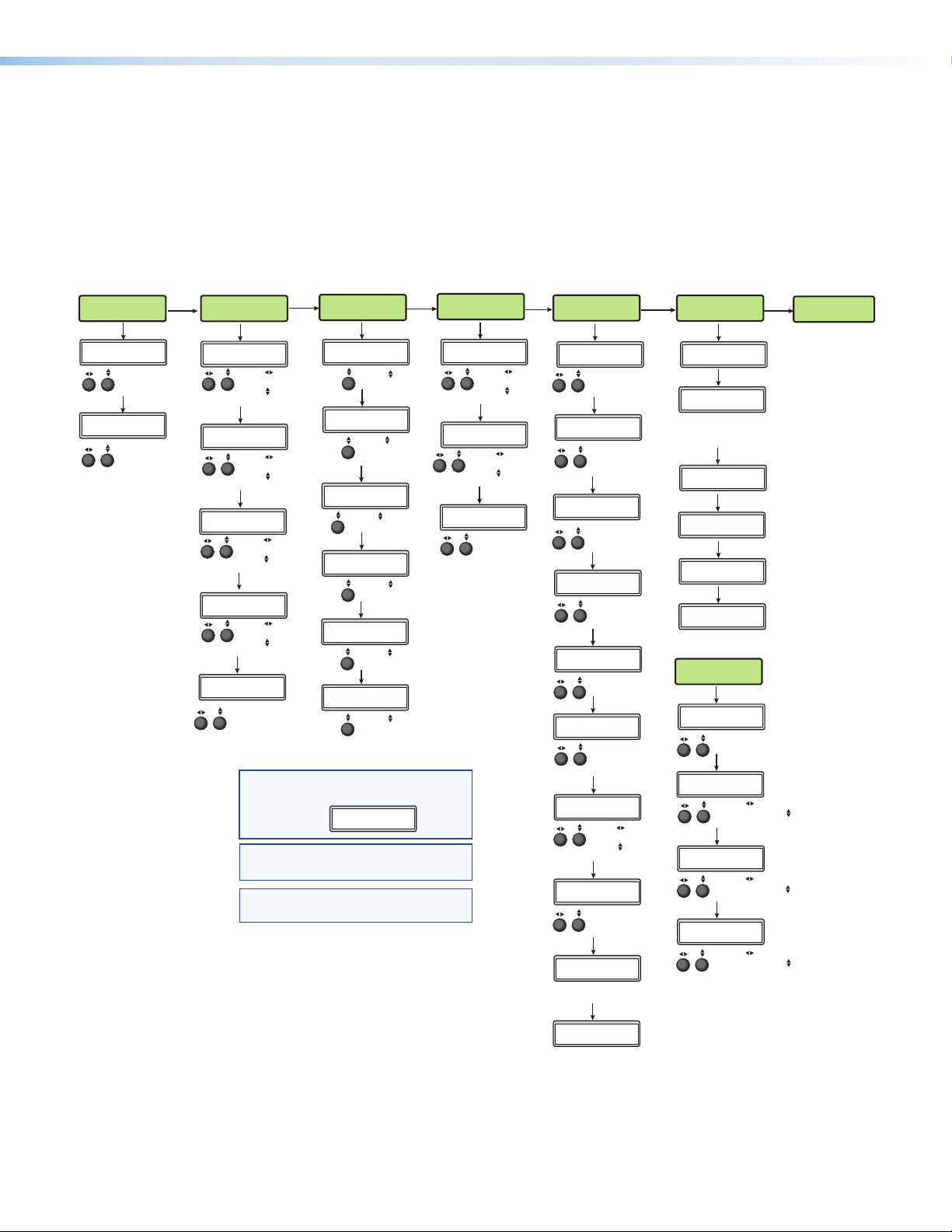
Edit Comm Settings (hidden)
To display and enter this menu, press and hold the Input 3 button and the Next button
simultaneously. The hidden menu appears.
This menu allows the user to edit the following IP settings:
DHCP mode, IP address, subnet mask, and gateway address.
Exit Menu
At this menu pressing Next exits the menu system and returns to the default cycle.
User
Presets
Recall Preset
<NA>
Rotate either to
select a preset to
recall settings.
Save Preset
<02>
Rotate either
to select a preset
to save current
settings to.
Menu
Next
Next
Picture
Control
x: H Center V
+00000 +00000
Rotate to adjust
Horiziontal value
Rotate to adjust
Vertical value.
x: H Size V
+01365 +00768
Rotate to adjust
Horiziontal value
Rotate to adjust
Vertical value.
x: Brit Cont
064* *064
Rotate to adjust
Brightness value
Rotate to adjust
Contrast value.
Next
x: Color Tint
064 064
Rotate to adjust
Color value
Rotate to adjust
Tint value.
Next
x: Detail
064*
Rotate either
to adjust Detail
value.
Menu
Next
Next
Next
NOTE: In the images above, the term “x:” refers to an
input or an output number. For example, if selecting
input 2 with HDMI, for
the display reads:
NOTE: Press Next to cycle through the submenus.
Press Menu to leave the current menu and go back to
the Main menu.
*NOTE To activate the hidden menu “Edit Comms”,
press and hold Input 3 and Next button simultaneously.
Input
Configuration
x: Input Type
RGB
Rotate to select
video input type.
x: Film Detect
<Off> On
Rotate to turn
Film Detect on
or off.
x:
H Start V
128 128
Rotate to adjust
Vertical Star t value.
x:
H Active V
1024* *768
Rotate to adjust
Horizontal Start value.
Tpix Phase
x:
1344* 16
Rotate to adjust
Pixel Phase value.
x:
EDID
1600x1200 @ 60Hz
Rotate to adjust
Total Pixel value
(* = default).
Input Configuration > Input Type,
2: Input Type
HDMI
Menu
Next
Next
Next
Next
Next
Next
Output
Configuration
x: Resolution
1024x1024 @60Hz
Rotate to adjust
Resolution value
Rotate to adjust
Refresh rate.
HDMI Format
x: AUTO
Rotate to select
output (1 or 2).
Rotate to select
format.
x: HDCP Note
<Off> On
Rotate either to
turn Note on or off.
Menu
Next
Next
Next
Advanced
Configuration
Next
Test Pattern
Color Bars
Rotate either to
select Test Pattern.
Next
Calibrate Pa nels
<NO> YES
Rotate either to
select Yes or No.
Next
x: Auto Image
Off
Rotate either to turn
Aiuto Image on or off.
Next
x: Aspect Ratio
Fill
Rotate either to select
Aspect Ratio mode.
Next
x: Auto Memory
On
Rotate either to turn
Auto Memory on or off.
Next
Capture/Recall
USB
Rotate either to
select Capture/Recall
format.
Next
Overscan
S-video 5.0%
Rotate to select
video format.
Rotate to select
value.
Next
Switch Type
Fade
Rotate either to
select Switch Type
(cut or fade).
Next
Temperature
96 F 35 C
Indicates Internal temperature
(not adjustable).
Next
Factory Reset
Hold Au to Img
Press and hold Auto Image
to reset unit to factory settings.
Menu
9600 RS232
This is set at the factory
and cannot be changed
in “Edit Comm Settings”
menu.
Gateway Address
<192>168.254.254
<255>255.000.000
Gateway Address
<000>000.000.000
View Comm
Settings
Next
Serial Po rt
Next
MAC Address
005A6003C24
Next
DHCP Mode
On
Next
IP Address
192.168.254.254
Next
Subnet Mask
255.255.000.000
Next
000.000.000.000
“Hidden” Menu *
Edit Comm
Settings
Next
DHCP Mode
<On>
Rotate either to turn
DHCP mode On or Off.
Next
IP Address
Rotate to select
octet field. Rotate
to change address.
Next
Subnet Mask
Rotate to select
octet field. Rotate
to change address.
Next
Rotate to select
octet field. Rotate
to change address.
Menu
Exit Menu
Press NEXT
Figure 8. Annotator Menu System Overview
Annotator 300 • Operation 16
Page 23

Using the Menus
To configure the Annotator 300 using any of the menus, do the following:
1. Press the Menu button repeatedly to reach the desired configuration menu.
2. Press the Next button repeatedly to go to the desired submenu.
3. The LCD shows the current values. Observe the LCD and rotate either (or both)
NOTES:
User Presets
Within this menu, up to 16 presets can be saved or recalled.
Save a user preset
1. From the default display cycle, press Menu to enter the User Presets submenu.
2. Press Next twice to go to the Save Preset menu.
3. Rotate either front panel Adjust knob ([{) to select a preset
4. Press Next to save the current image settings to the selected preset number.
Adjust knob to change the values as desired.
• Pressing the Menu button within any level takes the user back to the current top
level menu.
• When in any menu for approximately 25 seconds and no buttons have been pressed
or Adjust knobs rotated, the unit times out and returns to the default cycle.
Save Preset
<N/A>
(1 to 16) to save the current settings to. Default setting is <N/A>.
Select <N/A> and press Next to move to the next submenu without saving.
The Preset is saved and the LCD goes back to the top level User Preset menu.
NOTE: If an existing preset is chosen to save to, the previous settings are overwritten
in favor of the new (current) settings.
Recall a user preset
1. From the default display cycle press Menu to enter the User Presets submenu.
2. Press Next to go to the Recall Preset menu.
3. Rotate either front panel Adjust knob ([{) to select a preset
Recall Preset
<02>
(1 to 16) to recall as the current settings. Default setting is N/A.
Select <N/A> and press Next to move to the next submenu without recalling.
4. Press the Next button. The preset is recalled, the image changes to the recalled
settings, and the LCD goes back to the top level User Preset menu.
Annotator 300 • Operation 17
Page 24
Input Configuration
Within this menu, the inputs can be configured. Each input has different settings
depending on the signal format. Consult the tables below for signal formats per input and
possible adjustments per signal format.
To configure inputs:
1. From the top level Input Configuration menu, press the Next button to bring up the
input selection screen. The active input is displayed on the LCD with current signal
format.
NOTE: If the input shown is not the one to be adjusted, press the desired input
2. With the correct input displayed, rotate the right Adjust knob ([{) to change the
signal format (refer to table below for signal type per input).
Input 1 Input 2 Input 3
*Auto Detect *HDMI/DVI *DisplayPort
RGB
Auto YUV
RGBcvS
S-video
Composite
Figure 9. Signal Formats per Input (*= Default Value)
button.
3. Press the Next button to go to the next setting. If necessary, repeat pressing Next
until the desired level is attained. Refer to the table below for adjustable settings for
each signal format.
Input Format RGB YUVp/
HDTV
Film Detect X X X X X X X X X
H Start X X X X X X
V Start X X X X X X
Phase X X
Total Pixels X X
Active Pixels X X X X X X
Active Lines X X X X X X
EDID X X X X
YUVi RGBcvS S-vid Composite DVI HDMI DisplayPort
Figure 10. Adjustments Possible per Signal Format
4. At the desired setting (for example, Horizontal and Vertical Start on
input 1 with a YUVp/HDTV signal, see image at right), rotate both
1: H Start V
128 128
Adjust knobs ([{) to adjust the settings value as desired (here at
128).
5. Repeat steps 3 and 4 for each setting as desired.
6. When complete, press Menu once or Next repeatedly to return
to the top level menu. Alternatively, allow the unit to time out to return to the default
cycle.
Annotator 300 • Operation 18
Page 25

Output Configuration
Using this menu, resolutions and refresh rates, HDMI format, and HDCP note can be
selected and adjusted for an output. See the table below for resolution and refresh rates.
1. Press Next to bring up the Resolution submenu. In this submenu, the resolution and
refresh rate can be adjusted.
2. Rotate the left front panel Adjust knob ([) to adjust the resolution value, and rotate
the right Adjust knob ({) to adjust the refresh rate.
Resolution 23.98 Hz 24 Hz 25 Hz 29.97 Hz 30 Hz 50 Hz 59.94 Hz *60 Hz
640x480 X
800x600 X
1024x768 X
1280x768 X
1280x800 X
1280x1024 X
1360x768 X
1366x768 X
1440x900 X
1400x1050 X
1680x1050 X
1600x1200 X
1920x1200 X
480p X X
576p X
720p X X X X X X X X
1080i X X X
1080p X X X X X X X X
2048x1080 X X X X X X X X
* = Default
Figure 11. Output Resolution/Refresh Rate Table
3. Press Next to enter the next submenu, HDMI Format. Within this submenu the output
signal type (Auto, DVI RGB 444, RGB 444 Full, RGB 444 Limited, YUV 444 Full, or
YUV 444 Limited, YUV 422 Full, or YUV 422 Limited) can be selected.
4. Rotate either front panel Adjust knob ([{) to select the output HDMI format.
5. Press Next to enter the next submenu, HDCP Note. Within this submenu, the HDCP
note can be turned Off (default) or On. When the HDCP notification is turned On,
and an HDCP-encrypted input is sent to a display that is non-compliant, a green
background is displayed with a moving message reading “HDCP Content”. If HDCP
notification is Off, a black or muted output is displayed.
6. Rotate either front panel Adjust knob ([{) to turn the note off or on.
7. Press Next or Menu to return to the Output Configuration top level menu.
Annotator 300 • Operation 19
Page 26
Advanced Configuration
1
4
3
2
Touch to Start
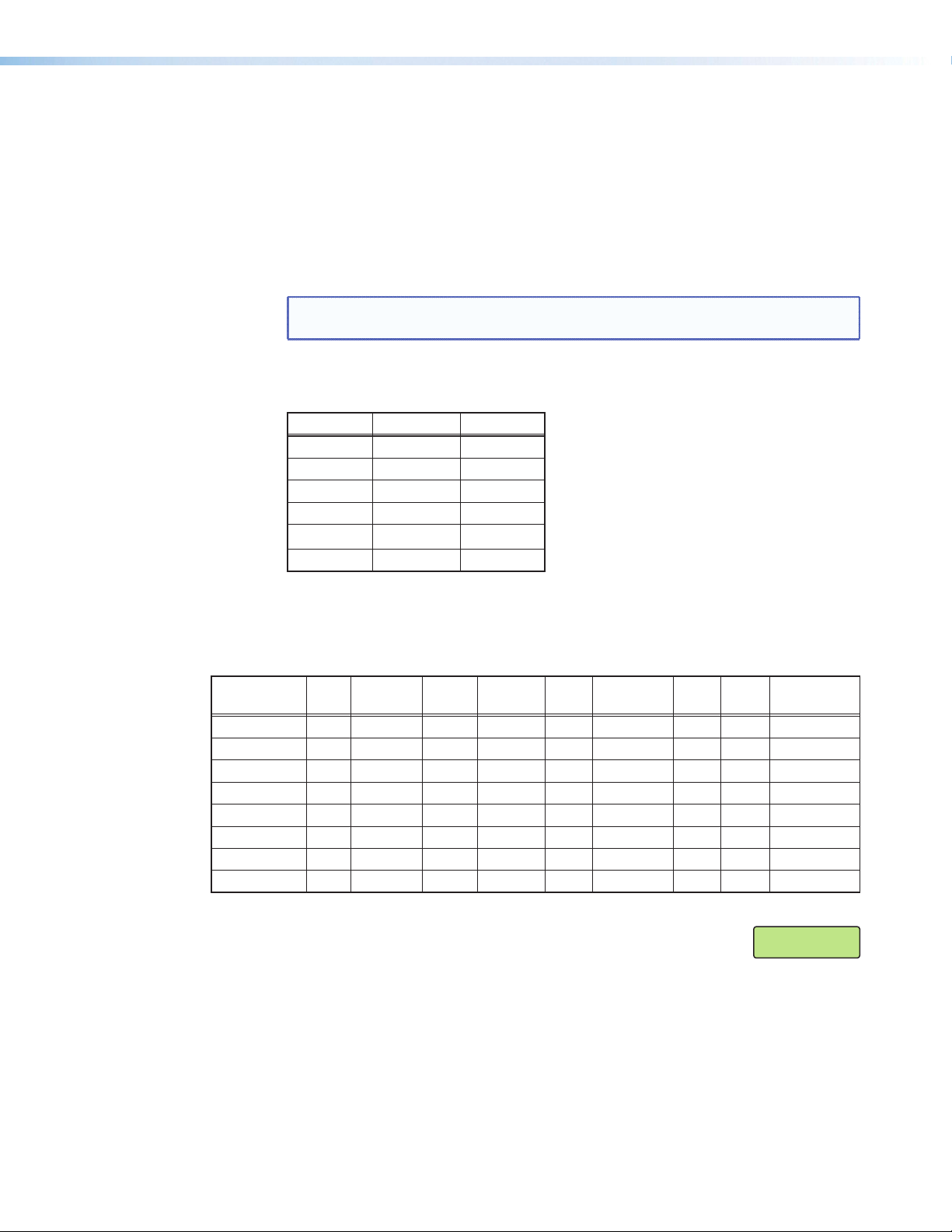
Within this menu: a test pattern can be selected to aid setting up the display, connected
touch panel displays can be calibrated, auto imaging, aspect ratio, and auto memory can
be set or turned on or off, the image capture and recall location can be set, the overscan
threshold set, and the switch effect chosen. In addition, the internal temperature can be
read, and the unit can be reset to factory default settings.
1. Within Advanced Configuration, press Next to enter the first sublevel, Test Pattern.
The following test pattern settings are available (None [no test pattern] is the default):
Ramp
Crosshatch
Crosshatch 4x4
White Field
White Field
Blue Mode
Crop
1.33 Aspect
Alternating
Color Bars
Pixels
1.78 Aspect
Alternating
Lines
Grayscale
1.85 Aspect 2.35 Aspect
Figure 12. Available Test Patterns
NOTE: The test patterns may vary based on the output rate selected. For example, if
a 4:3 rate is selected, then the 4:3 crosshatch (32x24) and aspect ratio crop patterns
appear. The raster border is independent of the aspect ratio, always surrounding the
active area of the screen.
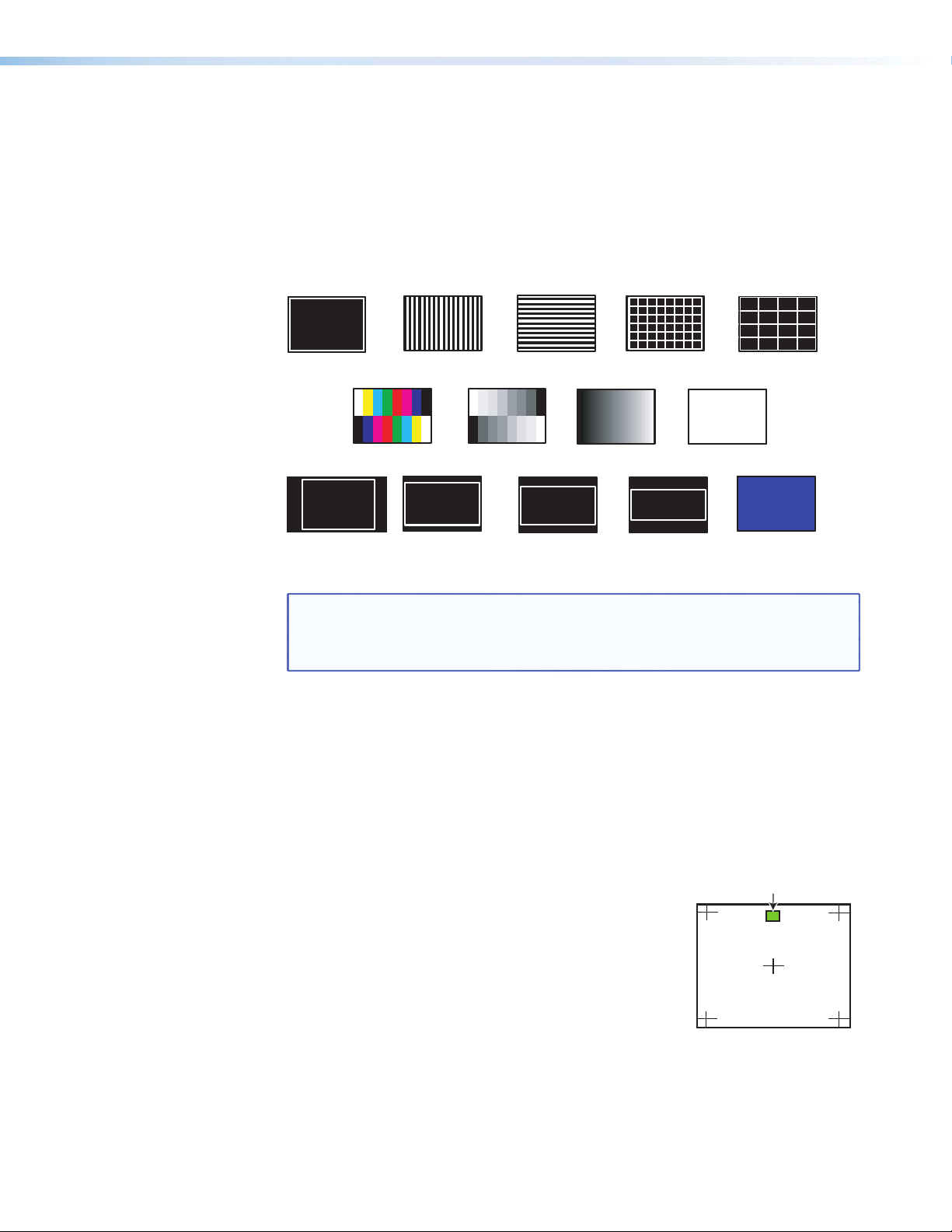
2. Press Next to cycle to the Calibrate Panels submenu.
a. Within the Advanced Configuration menu, select Yes and press Next to cycle to
Calibrate Panels.
b. Observe all connected touchpanel screens. On all screens a green box appears
at top center. To start the sequence, tap the box on one of the panel screens you
need to calibrate.
c. The box disappears and a crosshatch + appears in the upper left corner. Tap the
screen at the crosshatch.
d. The crosshatch re-appears at the top right corner.
Tap the crosshatch. The crosshatch re-appears in the
lower right.
e. Repeat by tapping the crosshatch as it reappears in
each corner, in sequence (see image at right)
5
and then tap the crosshatch when it appears in the
center of the screen.
f. After tapping the fifth (central) crosshatch, the unit
saves the calibration data and restarts the sequence by
showing the green box on all connected touchpanels.
g. Repeat for each connected touchpanel screen. Press any front panel button to
exit the sequence and save the data.
Annotator 300 • Operation 20
Page 27

3. Press Next to enter the next sublevel, Auto Image. The current active input and
setting status is displayed. With the applicable input showing, rotate either Adjust
knob ([{) to turn the Auto Image on or off.
4. Press Next to enter the next sublevel, Auto Memories, and rotate either Adjust knob
([{) to turn the Auto Memory on or off.
5. Press Next to enter the next sublevel, Aspect Ratio, and rotate either Adjust knob
([{) to select Fill or Follow.
6. Press Next to go to the next sublevel, Capture/Recall. Rotate either Adjust knob
([{) to select the location (Internal, USB, or Network) to save or recall captured
images.
7. Press Next to go to the next sublevel, Overscan. Rotate the left Adjust knob ([) to
set the signal type (RGB, YUV, RGBcvS, S-video, or composite video), and the right
Adjust knob ({) to set the overscan (None, 2.5%, or 5%) for the selected signal type.
8. Press Next to go to the next sublevel, Switch Type. Rotate either Adjust knob
([{) to select the switch type (Cut or Fade).
9. Press Next to go to the next sublevel, (internal) Temperature. This is view-only.
10. Press Next to go to the next sublevel, Factory Reset. Press and hold the front panel
Auto-Image button for 3 seconds to reset the unit to factory defaults.
View Comm Settings
Within this menu the current IP settings are only viewable. To make any adjustments, the
“hidden” Edit Comm Settings menu must be accessed (see below).
1. Press Next to go through each sublevel to view the following: Serial port (baud rate
and communication type), MAC address (cannot be changed), DHCP status (on or
off), IP address, subnet mask, and gateway address.
2. Press Next or Menu to return to the View Comm Settings menu.
To enter the “hidden” Edit Comms Settings menu, press and hold in the Input 3 button
and the Next button simultaneously. The Edit Comms Settings menu appears.
Edit Comm Settings
Exit Menu
1. Press Next to go through each sublevel to edit the following: DHCP (on or off), IP
address, subnet mask, and gateway address.
NOTE: The hardware address (the MAC address) is hard coded and cannot be
changed. In edit mode the MAC address is not displayed.
2. At each level, use both Adjust knobs to set new values as desired.
NOTES:
• For IP address, subnet mask, and gateway address settings, the left Adjust
knob moves between octets and the right Adjust knob changes the values.
• When already connected to a remote PC via LAN, changing the IP address
can result in the loss of connection.
• The Annotator 300 default IP address is 198.162.254.254.
3. Press Menu to exit the Edit Comm Settings menu, saving the new settings.
Within this menu press Next to exit the menu system and return to the default display
cycle.
Annotator 300 • Operation 21
Page 28
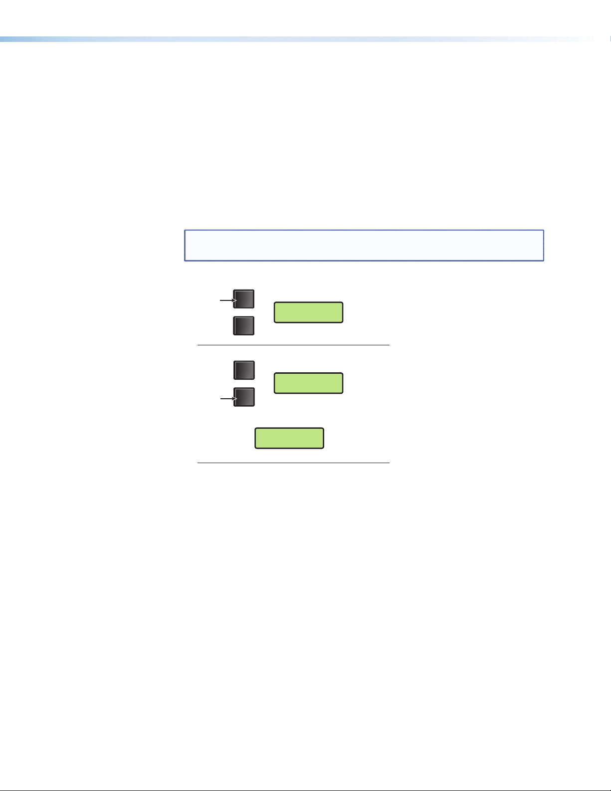
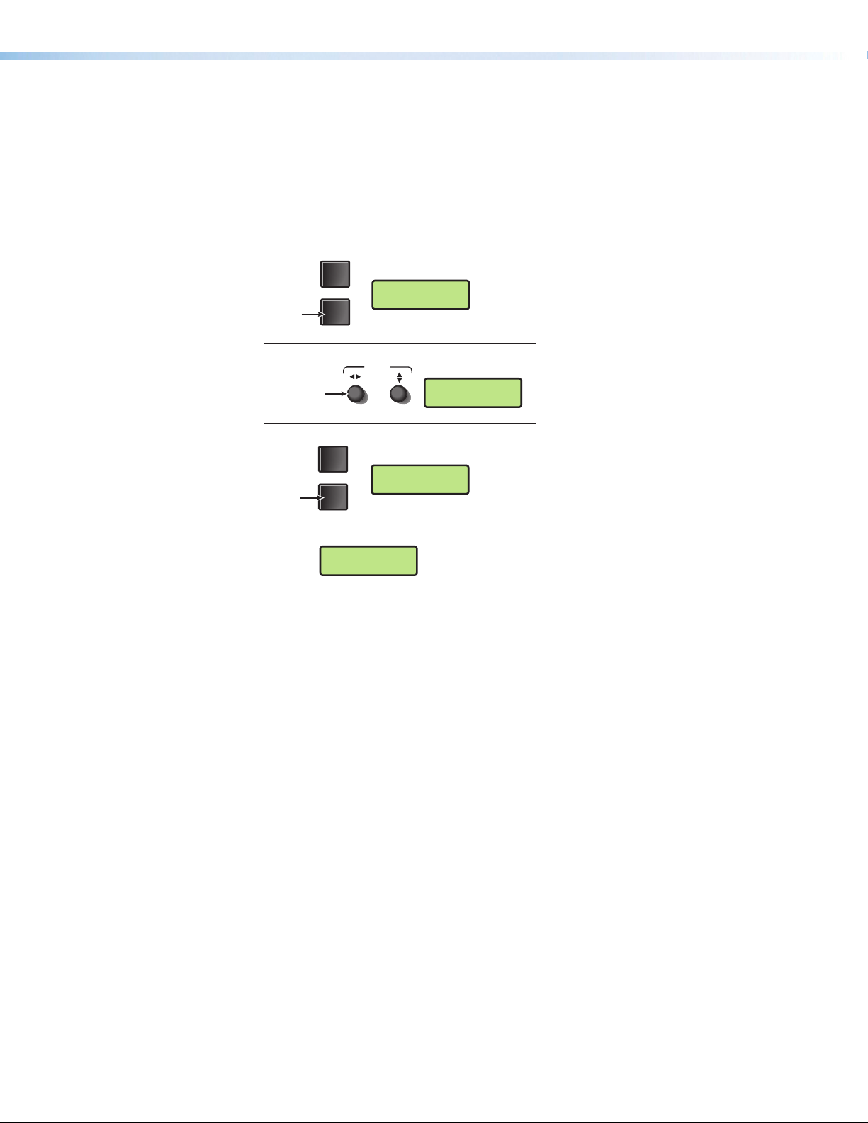
Capture/Recall Settings (front panel activated)
Step 1
A snapshot of the currently displayed image (including annotations) can be captured and
saved to the Annotator 300 memory using the front panel Capture/Recall button, the
Next button, and the two Adjust knobs. This image or any other saved image can then be
recalled and output to the active display at a later time.
To capture an image:
1. Press the Capture button. The LCD displays “To Confirm....Press Next”.
2. Press Next to confirm and to enter the Capture process. The LCD displays
“Capturing Image: <filename>”.
When the image is saved the LCD reverts to the default menu cycle.
NOTE: Custom image names can be used when image captures are initiated
using the appropriate SIS commands.
Press
Step 2
Press
CAPTURE
RECALL
MENU
NEXT
LCD screen displays
To Confirm...
Press Next
LCD screen displays
Capturing Image
<
filename>
LCD screen displays
Captured
<
filename>
Figure 13. Sequence for Capturing an Image
Annotator 300 • Operation 22
Page 29
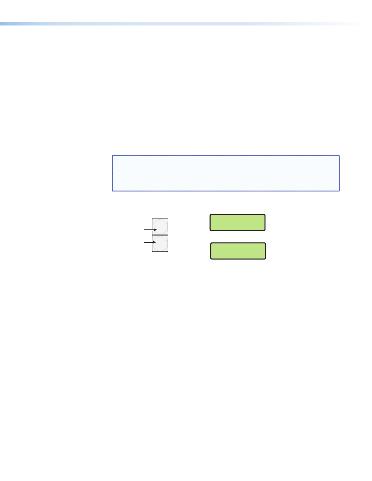
To recall an image:
Step 1
1. Press and release the Recall button. The LCD displays “Recall Image <None>”.
2. Use either Adjust knob to scroll through the saved images to the desired image.
3. Press Next to Recall the image. The LCD displays “Recalling: <filename>”.
When the image is fully downloaded, the LCD displays the name of the image and
“Recalled”, (for example, “IMG05.bmp Recalled”). The recalled image is displayed on
the active display.
CAPTURE
Press
RECALL
LCD screen displays
Recall Image
<
None>
Step 2
Rotate either
Adjust knob.
Step 3
Press
ADJUST
MENU
LCD screen displays
Recalling Image
NEXT
LCD screen displays
Recalled
IMG05.BMP
LCD screen displays
Recall Image
IMG05.BMP
IMG05.BMP
Figure 14. Sequence for Recalling an Image
To remove an image from the display:
1. Press and release the Recall button. The LCD displays “Recall Image <None>”.
2. Press Next. The LCD displays “Recall: <None>”. The current image is removed from
the display, but not from the Annotator 300 memory. To recall the image follow the
steps described in the “To recall an image” section above.
Annotator 300 • Operation 23
Page 30
Setting the Front Panel Locks (Executive Modes)
Press and
hold
2 seconds
The Annotator 300 has two levels of front panel security lock that limit the operation
of the device from the front panel.
Executive mode 0 (disabled) — The front panel is fully unlocked. This is the default
setting.
Executive mode 1 (enabled) — The front panel is completely locked. This mode can
only be enabled and disabled using SIS commands. See the “SIS Communication and
Control” section from page 31 onwards, for further details.
Executive mode 2 (enabled) — The front panel is locked except for input switching and
Auto Image.
Enabling or Disabling Executive Mode 2 from the Front Panel
NOTES:
• If the Annotator 300 is in Executive mode 0 (unlocked), this procedure
enables mode 2 (locked).
• If it is in Executive mode 2, this procedure enables mode 0 (unlocks the unit).
Press and hold the Menu and Next buttons to enable or disable the Executive Mode.
MENU
Executive Mode 2
Enabled
for about
.
LCD screen
displays either
OR
Executive Mode
NEXT
Disabled
Figure 15. Turning Executive Mode On or Off
When either Executive mode is enabled and a front panel action is attempted (other than
input switching and Auto Image), the LCD displays the status for 2 seconds.
Executive mode 2 can also be enabled or disabled by SIS commands. See the “SIS
Communication and Control” section, for SIS commands.
Annotator 300 • Operation 24
Page 31

On Screen Annotation
This section of the manual discusses on screen annotation and is in four sections:
• Touch Panel Configuration
• USB Port Connections
• Touchscreen Calibration
• Annotation Overview
The Annotator 300 is a high performance, hardware-based annotation processor for video
and computer-video sources. Annotating over motion video or still images is possible
using common touchscreen panels, and a standard keyboard and/or mouse. The
touchscreen panels are connected by USB, and device drivers can be uploaded to ensure
compatibility with the Annotator 300. For a full list of compatible panels visit
www.extron.com. Contact Extron if the device you wish to use is not listed.
Touch Panel Configuration
If a USB touchpanel is part of the system, confirm the panel is supported by the firmware
on the Annotator 300 by reviewing the compatibility list available on the product page
of the Extron website (www.extron.com). If the touchpanel is not supported by the
firmware, a supporting module must be uploaded to the Annotator 300 using PCS version
2.1 (or greater).
1. Connect to the Annotator 300 using the PCS 2.1 software.
2. From the icon ribbon, click on and open the Annotation Settings page.
3. In the Installed USB Devices section, click Add. The Add a USB Device
dialog box opens.
4. Find the touchpanel device in the list of available modules, or:
if the device is not present in the list but is available from the Extron website,
click on Check for Updates.
5. Select the module that supports your touchpanel and click Add. The dialog box
closes and the selected touchpanel is now listed in the Installed USB Devices
section.
To remove an installed touchpanel:
1. Connect to the Annotator 300 using the PCS software.
2. From the icon ribbon, click on and open the Annotation Settings page.
3. In the Installed USB Dvices section, select the installed USB device to be
removed, and click Remove. A Remove USB Device confirmation dialog box
opens.
4. Click Remove to remove the installed device, or click Cancel to exit the action
without removing the device.
Annotator 300 • On Screen Annotation 25
Page 32

USB Port Connections
Touchpanels can be connected via the two rear panel USB ports. By connecting multiple
USB hubs (see figure 20), up to 20 devices can be connected.
A number of common touchpanels are automatically supported. A mix of size and vendor
types can be connected simultaneously, but unsupported devices may cause adverse
affects. For a full list of compatible panels visit www.extron.com.
The USB ports also support standard USB keyboards and mice.
Before use, panel calibration is advised (see “Touchscreen Calibration” in this section).
Using a suitable USB A cable, connect a touchscreen device or hubs to the either of the
two USB A ports on the rear panel of the Annotator 300. Do not connect more than three
hubs in line (three deep).
NOTE: The Annotator 300 has one hub built into the product.
Figure 16. Connect USB Hubs for Multiple Devices
1 2 3 4
Annotator 300
USB #1
1 2 3 4
1 2 3 4
Hubs
1 2 3 4 1 2 3 4
Touchscreen Calibration
If a touchpanel screen is attached to the Annotator 300, the touch accuracy can be
calibrated using the Calibrate Panels setting in the Advanced configuration menu.
1. Within the Advanced Configuration menu, select Yes and press Next to cycle to
Calibrate Panels.
Observe all connected touchpanel screens. On all screens a green box appears at
top center. To start the sequence, tap the box on one of the panel screens you need
to calibrate.
1
Touch to Start
2
5
4
Figure 17. Sequence of Cross Positions for Setting the Touch Accuracy of a
Screen
3
2. The box disappears and a crosshatch + appears in the upper left corner. Tap the
screen at the crosshatch.
3. The crosshatch re-appears at the top right corner. Tap the crosshatch. The
crosshatch re-appears in the lower right.
Annotator 300 • On Screen Annotation 26
Page 33

4. Repeat by tapping the crosshatch as it reappears in each corner, in sequence (see
Figure 17 on previous page) and then tap the crosshatch when it appears in the
center of the screen.
5. After tapping the fifth (central) crosshatch, the unit saves the calibration data and
restarts the sequence by showing the green box on all connected touchpanels.
6. Repeat for each connected touchpanel screen. Press the front panel button Next to
exit the sequence and save the data.
Annotation Overview
The Annotator 300 output has the capability to include a graphical tool bar which is used
for annotation. The tool bar can be enabled or disabled as desired. When enabled, the
tool bar is visible down the right side of the display and allows selection of the following:
Inputs selection, Pointer, Auto Image, Freehand, Line, Arrow, Rectangle, Ellipse, Text,
Highlighter, Size select, Eraser, Color, Fill, Undo, Redo, Clear, Tools - Capture, Freeze,
Mute, Whiteboard, Spotlight, Zoom, and Pan.
Figure 18. Annotation Menu Examples
When clicking on the tool bar arrow , the tool bar slides in from the right side, and
can be accessed through a touch screen, or by using a standard mouse and/or keyboard
attached to the rear or front USB ports.
The tool bar disappears (hides) after a user-specified time-out.
If the time-out is set to zero, the tool bar remains on-screen indefinitely.
The time out can be set via the PCS software (see the PCS product specific help file)
or SIS commands (see SIS Communication and Control from page 31 onwards for
details).
NOTE: All on screen annotations are lost when power to the Annotator 300 is
recycled.
Annotator 300 • On Screen Annotation 27
Page 34

Default Annotation Buttons
Input selection — Selecting this button opens a pop-up palette
displaying the three inputs of the Annotator 300. Selecting any
input button switches the display to that input.
Pointer — Selecting this button changes the cursor to an extra-
large arrow of the currently selected color.
Auto-Image — On selection of this button, the unit performs an
auto image (automatic sizing, centering, and filtering to optimize
the output image on the currently selected input). A secondary
button appears to the left of the Auto Image button to confirm the
action is desired.
Freehand — Selecting this button allows the user to draw freely
on the display screen.
Line — Selecting this button allows the user to create a straight
line between two points.
Arrow — Selecting this button allows the user to create a straight
line between two points with an arrow at the end point.
Rectangle — Selecting this button allows the user to create a
rectangle with edges parallel to the raster.
Ellipse — Selecting this button allows the user to create an ellipse
between the primary and the opposite corners of a non-drawn
rectangle.
Text — Selecting this button allows the user to create on-screen
text with a keyboard connected to the rear USB port. Text
insertion begins either at the mouse operated cursor point, or
where the screen is touched. If no insertion point is defined, then
text is inserted at the end point of the previously active function.
Highlighter — Selecting this button allows the user to highlight
the video information, not the annotation.
Size — Select this button to adjust size of text and/or line weight
(not linked), after selecting a drawing or text function, such as line,
rectangle, or text. A secondary palette opens displaying either line
weight or text point size depending on the active function. From
the secondary palette, select the desired size button. Functions
this applies to are Text, Line, Arrow, Freehand, Highlighter, Arrows,
Rectangle, Ellipse, and Eraser.
Eraser — Select this to erase any non saved annotations on the
screen.
Color — Select this button to choose the color of any drawing
function (fill or outline), text, or pointer color. On selection, a
secondary palette opens with 16 color swatches. Select a color
as desired. The active function now uses the selected color.
Annotator 300 • On Screen Annotation 28
Page 35

Fill — Selecting this button in conjunction with selecting the
rectangle or ellipse button, allows the user to draw a solid shape
filled with the currently selected color.
Undo — Selecting this allows the user to undo the last 15
Completed annotations or undo a Clear action.
Redo — If selected while using the Undo function, it recreates the
last undone annotation.
Clear — Selecting this clears the screen of all unsaved
annotations, and can be undone with the Undo function.
Tools — Selecting the Tools button opens a secondary palette
containing the following advanced tools: Capture, Freeze, Mute,
Whiteboard, Spotlight, Zoom, and Pan. On selection of any tool,
the secondary palette closes. To reopen the palette, click on the
Tools button.
Capture — Select this to take a snapshot image of the current
program output, including annotations (but not any open OnScreen Display palettes). This captured image can be saved to the
Annotator 300 memory for later recall.
Freeze — Select this to freeze the live video. To unfreeze the
video, reselect this button or switch inputs.
Mute — Select this to mute the video input and display a black
screen. Annotations and menus are still visible. To unmute the
video, reselect the Mute button, or select the Whiteboard tool, or
switch inputs.
Whiteboard — Select this to create a white canvas for
annotations. No input video image is visible. To remove the white
canvas, reselect the Whiteboard button, select mute, or switch
inputs.
Spotlight — Select this to create an ellipse to focus on a specific
area of the screen, while the outer area’s brightness is greatly
reduced. The shape and size of the ellipse is adjustable by
dragging the cursor while outside of it, to any point. The ellipse
can be moved to any point by dragging the cursor while within the
ellipse.
Zoom — Select this to zoom in to a specific area of the screen.
Using the cursor, create a rectangle at the desired area and the
Annotator 300 zooms in to view that area. If the boundaries of
the area are beyond the zoom capabilities, then the view will not
change. To zoom out draw a small rectangle (<100 pixels, ~1 inch
x 1 inch) and the normal view is restored.
Pan — Selecting this while in zoom mode, allows the user to
move the focus to a new area. Place the cursor on a zoomed
image and drag to the desired area.
Annotator 300 • On Screen Annotation 29
Page 36

NOTES:
• For Freehand, Line, Arrow, and Highlighter functions, the start point is
where the screen is touched (by finger or stylus), or where the cursor
starts when holding down the primary mouse button. The finish point is
where the stylus or finger is lifted from the screen, or at the point where
the mouse button is released.
• For all drawn annotations, line color and weight are adjustable.
• For Rectangle and Ellipse functions, the primary corner is where the
screen is first touched (by finger or stylus), or where the cursor starts
when holding down the primary mouse button. The opposite corner is
where the stylus or finger is lifted from the screen, or at the point where
the mouse button is released. Unless the fill option is also selected, only
the rectangle or ellipse outline is drawn.
• Eraser and Highlighter size, text size, and line weight have discrete size
settings.
• A drawn, unfilled shape cannot be filled afterwards, and vice versa.
• A completed annotation is defined by lifting the finger or stylus from the
touchscreen, pressing the keyboard Enter key, or releasing the primary
mouse button.
• Using SIS commands, the Capture tool can be customized to send out
an unsolicited response, indicating an image is ready to be streamed
directly to an external PC.
Annotator 300 • On Screen Annotation 30
Page 37

SIS Communication and Control
The Annotator 300 can be operated and configured using Simple Instruction Set (SIS)
commands input via a PC or control system connected to either the front panel USB
port, or the rear panel RS-232, or Ethernet port. See J, H, and K, on page 9, and
“Ethernet Connection” section on page 106, for wiring details.
Front Panel Configuration Port
The USB mini B port is located on the front panel. It is used to connect to a host
computer for configuration using SIScommands with DataViewer or for updating firmware
with the Firmware Loader utility. Both are available at www.extron.com.
Ethernet Connection
Ethernet (LAN) Port
The rear panel Ethernet connector on the unit can be connected to an Ethernet LAN or
WAN. Communications between the unit and the controlling device is via Telnet (a TCP
socket using port 23). The TCP port can be changed if necessary. This connection makes
SIS control of the unit possible using a computer connected to the same LAN or WAN.
Ethernet Cabling
The Ethernet cable can be terminated as a straight-through cable or a crossover cable
and must be properly terminated for your application. See “Ethernet Connection”
section on page 106, for cable termination details.
Default IP Addresses
To access the Annotator 300 via the Ethernet port, you need the Extron IP address and
may need the subnet mask and the gateway address. If the IP address has been changed
to an address comprised of words and characters, the actual numeric IP address can be
determined using the ping (ICMP) utility (see “Ethernet Connection” section on page
106 for more details). If the addresses have not been changed, the factory-specified
defaults are:
IP address: 192.168.254.254, subnet mask: 255.255.0.0, gateway address: 0.0.0.0
Annotator 300 • SIS Communication and Control 31
Page 38

Establishing a Connection
Establish a network connection to the processor as follows:
1. Open a TCP socket to port 23 using the processor’s IP address.
NOTE: If the local system administrators have not changed the value, the factory-
specified default, 192.168.254.254, is the correct value for this field.
The processor responds with a copyright message including the date, the name of the
product, firmware version, part number, and the current date/time.
NOTES:
• If the processor is not password-protected, the device is ready to accept SIS
commands immediately after it sends the copyright message.
• If the processor is password-protected, a password prompt appears below
the copyright message.
2. If the processor is password protected, enter the appropriate administrator or user
password.
• If the password is accepted, the processor responds with Login User or
Login Administrator.
• If the password is not accepted, the Password prompt reappears.
Connection Time-outs
The Ethernet link times out after a designated period of time of no communications. By
default, this time-out value is set to five minutes but the value can be changed.
NOTE: Extron recommends leaving the default time-out at five minutes and
periodically issuing the Query (Q) command to keep the connection active. If there
are long idle periods, Extron recommends disconnecting the socket and reopening
the connection when another command must be sent.
Number of Connections
The Annotator 300 can have up to 200 simultaneous TCP connections, including all HTTP
sockets and Telnet connections. When the connection limit is reached, the processor
accepts no new connections until some have been closed. No error message or indication
is given that the connection limit has been reached. To maximize performance of an IP
Link device, the number of connections should stay low and unnecessary open sockets
should be closed.
Using Verbose Mode
Telnet connections to the processor can be used to monitor for changes that occur on the
processor, such as front panel operations and SIS commands from other Telnet sockets
or a serial port. For a Telnet session to receive change notices from the processor, the
Telnet session must be in verbose mode 1 or 3. In verbose mode 1 or 3, the Telnet socket
reports changes in messages that resemble SIS command responses.
Host-to-Processor Instructions
SIS commands consist of one or more characters per command field. They do not
require any special characters to begin or end the command character sequence. Each
processor response to an SIS command ends with a carriage return and a line feed (CR/
LF = ]), which signals the end of the response character string. A string is one or more
characters.
Annotator 300 • SIS Communication and Control 32
Page 39

Processor-Initiated Messages
When a local event such as a front panel operation occurs, the processor responds by
sending a message to the host. The processor-initiated messages are listed below.
With an Internet connection:
(c) Copyright 2014, Extron Electronics, ANNOTATOR 300, Vx.xx,
60-1316-01]
Ddd, DD MMM YYYY HH:MM:SS (day, date time. Tue, 14 Jun 2014 14:43:17)
The processor initiates the copyright message when powered on or when connection via
Internet protocol (IP) is established. Vx.xx is the firmware version number.
]Password:
The processor initiates the password message immediately after the copyright message
when the controlling system is connected using TCP/IP or Telnet and the processor is
password protected. The processor requires an administrator or user level password
before performing the commands entered.
NOTE: Password prompt is re-displayed if an incorrect password is entered.
]Login Administrator] and ]Login User]
The processor initiates the login message when a correct administrator or user password
has been entered. If the user and administrator passwords are the same, the processor
defaults to administrator privileges.
Reconfig]
The processor sends the Reconfig message whenever any change of the input frequency,
video format, or audio format; on the currently selected input is detected.
NOTE: Response is seen via verbose connections only.
Exen]
The processor initiates the Exe message when executive mode is toggled on or off from
the front panel. “n” is the executive mode status: 1 = on, 0 = off.
HplgOx]
The processor initiates the SIS response that is broadcast upon detection of a Hot Plug
event on output x.
Processor Error Responses
When the Annotator 300 receives an SIS command and determines that it is valid, it
performs the command and sends a response to the host device. If the processor is
unable to perform the command because the command is invalid or contains invalid
parameters, the processor returns an error response to the host. The error response
codes are:
E01 — Invalid input channel number (out of range) E22 — Busy
E10 — Invalid command E24 — Privilege violation
E11 — Invalid preset number E25 — Device not present
E12 — Invalid port number E26 — Maximum number of
E13 — Invalid parameter (out of range) connections exceeded
E14 — Command not available for this configuration E27 — Invalid event number
E17 — Invalid command for this signal type E28 — Bad filename/file not
found
Annotator 300 • SIS Communication and Control 33
Page 40

Using the Command/Response Table for SIS Commands
The command/response table follows this section. Lowercase letters are acceptable
in the command field except where indicated. The table below shows the hexadecimal
equivalent of ASCII characters used in the command/response tables.
ASCII to HEX Conversion Table
space
Figure 19. ASCII to Hexadecimal Conversion
Symbols are used throughout the table to represent variables in the command/response
fields. Command and response examples are shown throughout the table.
Symbol Definitions
] = Carriage return with line feed
| or } = Carriage return with no line feed
• = Space
•
E or W = Escape key
NOTE: If unit does not support or recognize the entered commands, nothing will
happen and no response is issued.
X! = Input selection, 1 to 3
X@ = Output selection:
0 = All outputs (Only available for Video Mute)
1 = Output 1 Only (HDMI)
2 = Output 2A Only (HDMI)
3 = Output 2B Only (DTP)
X# = Input video format:
0 = Auto Detect (Default) 4 = S-Video
1 = RGB 5 = Composite
2 = Auto YUV 6 = HDMI/DVI
3 = RGBcvS 7 = DisplayPort
X$ = H/V start — 0 to 255 (default midpoint = 128, translates to the default value in the
input lookup tables)
X% = Detected Input Video Format:
0 = No signal present 5 = Composite
1 = RGB 6 = DVI
2 = Auto YUV 7 = HDMI
3 = RGBcvS 8 = DisplayPort
4 = S-Video
Annotator 300 • SIS Communication and Control 34
Page 41

X^ = Pixel phase — 0 to 63 (default = 31)
X& = Total pixels — (±512 of the default value)
X* = Active pixels — (±512 of the default value)
X( = Active lines — (±512 of the default value)
X1) = Off/disable (0) or on/enable (1)
X1! = Input standard:
0 = No signal 3 = SECAM
1 = NTSC - = N/A (when input is set to a high resolution signal format)
2 = PAL
X1@ = Internal temperature (in degrees Celsius)
X1# = Horizontal and vertical frequencies (format is three digit with single decimal
and leading zeros for example, 075.3)
X1$ = Text label – up to 16 characters
NOTE: User and input presets saved without a name will be saved with default “USER
PRESET XX” or “INPUT PRESET XXX” (for example. “USER PRESET 11” or “INPUT
PRESET 005”.
X1% = Picture adjustment — 0 to 127 (default 64)- (Three digit response – 0 padding)
X1^ = H or V position (range -11000 to +11000)
X1& = H or V size (range 10 to 11000)
X1* = Text string up to 32 characters drawn from the alphabet (A-Z), digits (0-9), minus
sign/hyphen (-). No blank or space characters are permitted as part of a name.
No distinction is made between upper and lower case. The first character must be
an alpha character. The last character must not be a minus sign/hyphen
X2) = Test patterns:
0 = off (default) 8 = ramp
1 = Crop 9 = white field
2 = alternating lines 10 = 1.33 aspect ratio
3 = alternating pixels 11 = 1.78 aspect ratio
4 = crosshatch 12 = 1.85 aspect ratio
5 = 4x4 crosshatch 13 = 2.35 aspect ratio
6 = color bars 14 = blue mode
7 = grayscale
Annotator 300 • SIS Communication and Control 35
Page 42

X2! = Scaler resolution:
NOTE: Unless otherwise indicated, resolutions below are all at a 60 Hz refresh rate.
10 = 640x480 29 = 720p @ 25 Hz 48 = 2048x1080 @ 25 Hz
11 = 800x600 30 = 720p @ 29.97 Hz 49 = 2048x1080 @ 29.97 Hz
12 = 1024x768 31 = 720p @ 30 Hz 50 = 2048x1080 @ 30 Hz
13 = 1280x768 32 = 720p @ 50 Hz 51 = 2048x1080 @ 50 Hz
14 = 1280x800 33 = 720p @ 59.94 Hz 52 = 2048x1080 @ 59.94 Hz
15 = 1280x1024 34 = 720p @ 60 Hz (default) 53 = 2048x1080 @ 60 Hz
16 = 1360x768 35 = 1080I @ 50 Hz 201 = Custom output rate 1
17 = 1366x768 36 = 1080I @ 59.94 Hz 202 = Custom output rate 2
18 = 1440x900 37 = 1080I @ 60 Hz 203 = Custom output rate 3
19 = 1400x1050 38 = 1080p @ 23.98 Hz
20 = 1600x900 39 = 1080p @ 24 Hz
21 = 1680x1050 40 = 1080p @ 25 Hz
22 = 1600x1200 41 = 1080p @ 29.97 Hz
23 = 1920x1200 42 = 1080p @ 30 Hz
24 = 480p @ 59.94 Hz 43 = 1080p @ 50 Hz
25 = 480p @ 60 Hz 44 = 1080p @ 59.94 Hz
26 = 576p @ 50 Hz 45 = 1080p @ 60 Hz
27 = 720p @ 23.98 Hz 46 = 2048x1080 @ 23.98 Hz
28 = 720p @ 24 Hz 47 = 2048x1080 @ 24 Hz
X2@ = EDID emulation:
NOTE: Unless otherwise indicated, resolutions below are all at a 60 Hz refresh rate.
0 = Automatic; match current output resolution (LCD reads “MATCH OUTPUT”)
1 = Output #1 (HDMI Connector)
2 = Output #2A (HDMI Connector)
3 = Output #2B (DTP Connector)
10 = 640x480 29 = 720p @ 25 Hz 48 = 2048x1080 @ 25 Hz
11 = 800x600 30 = 720p @ 29.97 Hz 49 = 2048x1080 @ 29.97 Hz
12 = 1024x768 31 = 720p @ 30 Hz 50 = 2048x1080 @ 30 Hz
13 = 1280x768 32 = 720p @ 50 Hz 51 = 2048x1080 @ 50 Hz
14 = 1280x800 33 = 720p @ 59.94 Hz 52 = 2048x1080 @ 59.94 Hz
15 = 1280x1024 34 = 720p @ 60 Hz (default) 53 = 2048x1080 @ 60 Hz
16 = 1360x768 35 = 1080I @ 50 Hz 81 = 2560x1440 @ 60 Hz
17 = 1366x768 36 = 1080I @ 59.94 Hz 82 = 2560x1600 @ 60 Hz
18 = 1440x900 37 = 1080I @ 60 Hz 201 = Custom EDID
19 = 1400x1050 38 = 1080p @ 23.98 Hz 202 = Custom EDID
20 = 1600x900 39 = 1080p @ 24 Hz 203 = Custom EDID
21 = 1680x1050 40 = 1080p @ 25 Hz
22 = 1600x1200 41 = 1080p @ 29.97 Hz
23 = 1920x1200 42 = 1080p @ 30 Hz
24 = 480p @ 59.94 Hz 43 = 1080p @ 50 Hz
25 = 480p @ 60 Hz 44 = 1080p @ 59.94 Hz
26 = 576p @ 50 Hz 45 = 1080p @ 60 Hz
27 = 720p @ 23.98 Hz 46 = 2048x1080 @ 23.98 Hz
28 = 720p @ 24 Hz 47 = 2048x1080 @ 24 Hz
Annotator 300 • SIS Communication and Control 36
Page 43

X2$ = EDID Table; 128 or 256 Bytes.
X2% = User presets — 1 to 16
X2^ = Input presets — 1 to 128
X2* = On-screen menu/cursor time-out (default = 10) /Output sync time-out
(default = 501-never),
0 = Menu/cursor never times out/output sync is instantly disabled with no active
input
1 to 500, in 1 second increments,
501 = output sync never times out
X2( = Executive mode status
0 = Off / disabled (default)
1 = Exe Mode 1 - Complete front panel lockout
2 = Exe Mode 2 - Partial front panel lockout (only input selection and Auto-Image
are still available
X3* = Overscan (Applied only to SMPTE [NTSC/PAL, 480p – 1080p] input rates)
0 = 0.0% (Default for RGB, HDMI, DisplayPort)
1 = 2.5% (Default for YUV Auto, RGBcvS, S-Video, and Composite video)
2 = 5.0%
X3( = Aspect ratio
1 = Fill (fills entire output raster) (default)
2 = Follow (follows input native aspect ratio)
X4) = Screen Saver modes
1 = Black screen (Default)
2 = Blue output
X4@ = Video Mute
0 = Unmute video/sync
1 = Mute video to black
2 = Mute video and sync
X4# = Auto-Image Threshold Value
0 (black) through 100 (white), default = 25
X4$ = HDCP status
0 = No sink or source device detected
1 = Sink or source detected with HDCP
2 = Sink or source detected but no HDCP is present
X4% = Video Switching Effect
0 = Cut
1 = Fade through Black
X4^ = HDCP Mode
0 = AUTO – HDMI output is only encrypted when viewing an encrypted input –
slower switching (default)
1 = ON – HDMI output is always encrypted regardless of input selection –
faster switching
Annotator 300 • SIS Communication and Control 37
Page 44

X4* = HDMI Output Format:
0 = auto (based on the display EDID: default)
1 = DVI RGB 444
2 = RGB 444 Full
3 = RGB 444 Limited
4 = YUV 444 Full
5 = YUV 444 Limited
6 = YUV 422 Full
7 = YUV 422 Limited
X4( = Auto Output Format Status:
0 = Output not connected
1 = DVI RGB 444
2 = RGB 444 Full
3 = RGB 444 Limited
4 = YUV 444 Full
5 = YUV 444 Limited
6 = YUV 422 Full
7 = YUV 422 Limited
X5) = Annotation type:
0 = eraser 7 = rectangle
1 = pointer 8 = text tool
2 = freehand 9 = spotlight
3 = highlighter 10 = zoom tool
4 = vector line 11 = pan tool
5 = arrow line (arrow appears at the endpoint of the vector)
6 = ellipse
X5! = Font selection — 16 character file name including *.TTF extension,
0 = default font (DeJaVuSans)
X5@ = Font size — 8 to 63 point font (default = 18 pt)
X5# = Line color — 6 bit RGB, 64 total colors
000000 = Black
010000 = Dark red (33%)
100000 = Medium red (66%)
110000 = Bright red (100%)
001100 = Bright green (66%)
000011 = Bright blue (default)
Format:
011011
Red
Value
Green
Value
Blue
Value
111111 = White
010101 = Dark gray (33%)
X5$ = Line weight, eraser, or highlighter width — 1 to 63 pixels wide (default = 8)
X5^ = On-screen clock:
0 = disabled (default)
1 = date and time
2 = time only
3 = date only
X5& = Annotation coordinates — 8 digit number with first four being the X coordinate,
the last four the Y coordinate, limits = 1000,1000. Fixed for any output rate.
Example, (0,0) = 00000000 = top left; (500,500) = 05000500 = screen center.
X5* = Audio input type
0 = None – Input muted (EDID has no CEA extension)
1 = LPCM-2Ch (LPCM-2Ch audio requested from source via EDID)
2 = Full Digital (allows any digital audio format from source via EDID)
Annotator 300 • SIS Communication and Control 38
Page 45

X5( = All ports (0), USB device (1-64)
X6! = Video Signal Status
0 = Video / TMDS signal not detected
1 = Video / TMDS signal detected
X6@ = Power Save modes
0 = Full Power mode (Default)
1 = Low Power state
X6# = Screen Saver Status
0 = Active Input; timer not running
1 = No active input; timer is running; output sync still active
2 = No active input; timer has expired; output sync disabled
X6$ = File location
0 = Internal Flash
1 = Image Quick Capture PC (requires Image Quick Capture software)
2 = Attached USB drive (Only ONE USB drive can be connected)
3 = Network location (location must be configured or E25 will be issued)
X6% = Image Capture File Format
1 = JPG
2 = BMP (default)
X6& = Network folder path (spaces not allowed)
Example: 10.13.198.131/AnaheimCourt/Room20
X6* = Printer URI address
Example: lpd://197.168.254.201
NOTES:
• “lpd” must be lower case
• Contact your IT department to determine if your printer supports postscript
printing via LPD.
X6( = Auto Annotation Clear
0 = Disabled (default)
1 = Clear after an input switch
2 = Clear after an input switch or when a new input frequency is detected
X7! = Output Group Selection
0 = All outputs (Default)
1 = Output 1 Only (HDMI)
2 = Output 2A and 2B Only (HDMI & DTP)
3 = None
X7@ = White/Blackboard status
0 = Disabled (Default)
1 = Whiteboard is enabled
2 = Blackboard is enabled
X7# = Auto Switch Mode
0 = Disable (Default)
1 = Gives priority to the highest numbered active input
2 = Gives priority to the lowest numbered active input
X7$ = DTP Output Format
0 = DTP format (Default)
1 = HDBaseT Format
Annotator 300 • SIS Communication and Control 39
Page 46

X7% = Keyboard Locale Selection
1033 = US Keyboard layout (Default)
1031 = German Keyboard layout
1034 = Spanish Keyboard layout
1036 = French Keyboard layout
2057 = Great Britain Keyboard layout
X7^ = Filename/prefix name without extension (12 characters)
X7& = Filename with extension
X7* = Configuration type
0 = IP config (ip.cfg)
1 = Event config (event.cfg)
2 = Box specific parameters (box.cfg)
X7( = Number of copies to print (printer quantity): 1-50 (default = 1)
Annotator 300 • SIS Communication and Control 40
Page 47

Command ASCII command
(host to processor)
Input Switching and Configuration
Input selection
Select input
View current input
X!! InX!] Select video from input X!.
!
Input video format
Set format
View format
View input standard
EX!*X#ITYP
EX!ITYP
EX!ISTD
(tagged response in verbose
mode 2/3)
}
}
}
Input EDID
Specify an EDID value
View EDID value
Save an outputs EDID
Export EDID file
Import an EDID file
EAX!*X2@EDID
EAX!EDID} X2@]
ESX@*X2@EDID
EE X2@,EDID} X2$]
EIX2@,X2$EDID}
}
}
Response
(processor to host)
X!]
ITypX!*X#*X%] Set input X! to video format X#.
Additional description
View currently selected input source.
Detected format X% is also reported in
response
X#*X%] View video format of input X!.
Detected format X% is also reported in
response
X!*X1!]
ISTD X!*X1!]
EdidX!*X2@] Set EDID resolution and refresh X2@
EdidAX!*X2@]
EdidSX@*X2@] Set output X@ EDID to X2@.
EdidIX2@] Imports user defined EDID to X2@
View video standard X1! for input X!.
Verbose mode (2/3)
for input X!.
View EDID resolution and refresh X2@
for input X!.
Verbose mode (2/3)
(Valid for X2@ = 201, 202, 203 only,
and X@ = 1, 2 and 3 only.)
Exports EDID table X2$.
(valid for X2@ = 201, 202, 203 only).
Auto-Image
Enable auto image
Disable auto image
Execute auto image
Execute and Fill
Execute and Follow
View auto image
NOTE: X! = Input selection; 1 – 3
X@ = Output selection: 0 = All outputs (Only available for Video Mute), 1 = Output 1 Only (HDMI),
2 = Output 2A Only (HDMI), 3 = Output 2B Only (DTP)
X# = Input video format; 0 = Auto detect (default), 1 = RGB, 2 = Auto YUV, 3 = RGBcvS, 4 = S-video,
5 = Composite video, 6 = HDMI/DVI, 7 = DisplayPort
X% = Detected Input Video Format: 0 = No signal present, 1 = RGB, 2 = Auto YUV, 3 = RGBcvS, 4 = S-Video,
5 = Composite, 6 = DVI, 7 = HDMI, 8 = DisplayPort
X1)
= 0 (off/disable), 1 (on/enable)
X1! = Input standard: 0 = No signal, 1 = NTSC, 2 = PAL, 3 = SECAM, - = N/A (when input is set to a high
resolution signal format)
X2@ = EDID emulation: see page 36 for EDID resolution and refresh rates
X2$ = EDID Table; 128 or 256 Bytes.
X!*1A ImgX!*1] Enable Auto image for input X! (only
X!*0A ImgX!*0] Turn off auto image for input X! (only
A
1*A
2*A
X!A X1)] View auto image setting for input X!.
Img0]
Img1]
Img2]
available for input 1).
available for input 1).
Execute auto image for current input.
Execute auto image and fill entire
output.
Execute auto image and follow the
input’s aspect ratio.
Annotator 300 • SIS Communication and Control 41
Page 48

Command/Response Table for SIS Commands
Command ASCII command
(host to processor)
Auto-Image threshold value
Response
(processor to host)
NOTE: Luminosity value which the processor defines as active video for Auto-Image.
Set threshold value
View threshold value
Horizontal start
Specify a value
Increment value
Decrement value
View value
Vertical start
Specify a value
Increment value
Decrement value
View value
EX4#ALVL} AlvlX4#]
EALVL} X4#]
EX$HSRT} HsrtX!*X$]
E+HSRT} HsrtX!*X$]
E-HSRT} HsrtX!*X$]
EHSRT} X$]
EX$VSRT} VsrtX!*X$]
E+VSRT} VsrtX!*X$]
E-VSRT} VsrtX!*X$]
EVSRT} X$]
Additional description
Set global Auto image luminosity value
X4#.
View global Auto image luminosity
value X4#.
Set horizontal location of first active
pixel in active input.
Increase value.
Decrease value.
View horizontal location of first active
pixel in active input.
Set vertical location of first active line in
active input.
Increase value.
Decrease value.
View vertical location of first active line
in active input.
Pixel phase (RGB and YUV-HD input signals only)
Specify a value
Increment value
Decrement value
View value
Total pixels (RGB and YUV-HD only)
Specify a value
Increment value
Decrement value
View value
Active pixels
Specify a value
Increment value
Decrement value
View value
NOTE: X! = Input selection; 1 – 3
X$ = H/V start — 0 to 255 (default midpoint = 128, translates to the default value in the input lookup tables
X^
= Pixel phase; 0-63 (default = 31)
X&
= Total pixels; (±512 of the default value)
X*
= Active pixels; (±512 of the default value)
X4# = Auto-Image Threshold Value; 0 (black) through 100 (white), default = 25
EX^PHAS} PhasX!*X^]
E+PHAS} PhasX!*X^]
E-PHAS} PhasX!*X^]
EPHAS} X^]
EX&TPIX} TpixX!*X&]
E+TPIX} TpixX!*X&]
E-TPIX} TpixX!*X&]
ETPIX} X&]
EX*APIX} ApixX!*X*]
E+APIX} ApixX!*X*]
E-APIX} ApixX!*X*]
EAPIX} X*]
Set pixel phase to specified value for
active input.
Increase value.
Decrease value.
View pixel phase.
Set total pixels to specified value for
active input.
Increase value.
Decrease value.
View total pixels.
Set active pixels to specified value for
active input.
Increase value.
Decrease value.
View active pixels.
Annotator 300 • SIS Communication and Control 42
Page 49

Command ASCII command
(host to processor)
Active lines
Specify a value
Increment value
Decrement value
View value
3:2, 2:2, 24:1 Film mode detect
Enable film detect
Disable film detect
View setting
EX(ALIN} AlinX!*X(]
E+ALIN} AlinX!*X(]
E-ALIN} AlinX!*X(]
EALIN} X(]
EX!*1FILM} FilmX!*X1)]
EX!*0FILM} FilmX!*X1)]
EX!FILM} X1)]
Picture Adjustments
Video mute
Unmute output
X7!*0B VmtX7!*00] Restore picture for output X7!.
Response
(processor to host)
Additional description
Set active lines to specified value for
active input.
Increase value.
Decrease value.
Show active lines.
Turn film mode detection on.
Turn film mode detection off.
View setting.
Mute output video
Mute output sync and
video
Query output state
Color
Specify a value
Increment value
Decrement value
View value
Tint
Specify a value
Increment value
Decrement value
View value
Contrast
Specify a value
Increment value
Decrement value
View value
Brightness
Specify a value
Increment value
Decrement value
View value
X7!*1B Vmt X7!*01] Mute video only on output X7!.
X7!*2B Vmt X7!*02] Mute sync and video on output X7!.
X7!B X4@] Queries mute status of output X7!..
X1%
X1%
.
.
X1%
.
X1%
.
EX1%COLR} ColrX!*X1%]
E+COLR} ColrX!*X1%]
E-COLR} ColrX!*X1%]
ECOLR} X1%]
EX1%TINT} TintX!*X1%]
E+TINT} TintX!*X1%]
E-TINT} TintX!*X1%]
ETINT} X1%]
EX1%CONT} ContX!*X1%]
E+CONT} ContX!*X1%]
E-CONT} ContX!*X1%]
ECONT} X1%]
EX1%BRIT} BritX!*X1%]
E+BRIT} BritX!*X1%]
E-BRIT} BritX!*X1%]
EBRIT} X1%]
Set color level to
Increase value.
Decrease value.
Show color level.
Set tint level to
Increase value.
Decrease value.
Show tint level.
Set contrast level to
Increase value.
Decrease value.
Show contrast level.
Set brightness level to
Increase value.
Decrease value.
Show brightness level.
NOTE: X! = Input selection; 1 – 3
X( = Active lines — (±512 of the default value)
X1)
= 0 (off/disable), 1 (on/enable)
X1% = Picture adjustment; 0 to 127 (default 64) (Three digit response – 0 padding)
X4@ = Video Mute: 0 = Unmute video/sync, 1 = Mute video to black, 2 = Mute video and sync
X7! = Output Group Selection; 0 = All outputs (Default), 1 = Output 1 Only (HDMI), 2 = Output 2A and 2B Only
(HDMI & DTP), 3 = None
Annotator 300 • SIS Communication and Control 43
Page 50

Command ASCII command
Detail filter
Specify a value
Increment value
Decrement value
View value
Horizontal shift
Specify a value
Increment value
Decrement value
View value
Vertical shift
Specify a value
Increment value
Decrement value
View value
Horizontal size
Specify a value
Increment value
Decrement value
View value
(host to processor)
EX1%HDET} HdetX!*X1%]
E+HDET} HdetX!*X1%]
E-HDET} HdetX!*X1%]
EHDET} X1%]
EX1^HCTR} HctrX!*X1^]
E+HCTR} HctrX!*X1^]
E-HCTR} HctrX!*X1^]
EHCTR} X1^]
EX1^VCTR} VctrX!*X1^]
E+VCTR} VctrX!*X1^]
E-VCTR} VctrX!*X1^]
EVCTR} X1^]
EX1&HSIZ} HsizX!*X1&]
E+HSIZ} HsizX!*X1&]
E-HSIZ} Hsiz
EHSIZ} X1&]
Response
(processor to host)
X!
*X1&]
Additional description
Set detail level to
Increase value.
Decrease value.
Show detail level.
Set horizontal position to
Shift position right.
Shift image left.
Show horizontal position value.
Set vertical position to
Shift image down.
Shift image up.
Show vertical position value.
Set horizontal size to
Widen the image.
Make image narrower.
Show horizontal size value.
X1%
.
X1^
X1&
X1^
.
.
.
Vertical size
Specify a value
Increment value
Decrement value
View value
NOTE: X! = Input selection; 1 – 3
X1% = Picture adjustment; 0 to 127 (default 64) (Three digit response – 0 padding)
X1^ = H or V position (range -11000 to +11000)
X1& = H or V size (range 10 to 11000)
EX1&VSIZ} Vsiz
E+VSIZ}
E-VSIZ}
EVSIZ}
X!
VsizX!*
VsizX!*
X1&]
*X1&]
X1&]
X1&]
Set vertical size to
Make the image taller.
Make image shorter.
Show vertical size value.
X1&
.
Annotator 300 • SIS Communication and Control 44
Page 51

Command ASCII command
(host to processor)
Response
(processor to host)
Output Configuration
Output scaler rate
Set output rate
View output rate
Digital output format
Set format
View setting
Screen saver (runs when no active video in selected input)
Set mode
View mode
Set time duration
View time duration
View screen saver status
EX2!RATE} RateX2!]
ERATE} X2!]
EX@*X4*OTYP} OtypX@*X4**X4(]
EX@OTYP} X4**X4(]
EMX4)SSAV} SsavMX4)] Sets the screen saver mode to X4)
EMSSAV} X4)]
ETX2*SSAV} SsavTX2*]
ETSSAV} X2*]
ESSSAV} X6#] View screen saver status X6#.
Additional description
Select output resolution and refresh
rate.
Show selected output rate.
Sets the output color space/format for
digital output to X4*. Automatic format
X4( is also reported in the response.
View the output color space for digital
output X@. Automatic format X4( is
also reported in the response.
(default: 1 = black).
View the current screen saver mode
X4).
Sets the screen saver time duration
X2* seconds (default: 501 = never).
View the screen saver time duration
X2*.
NOTE: When the Screen Saver mode automatically enables or disables output sync (entering or exiting
the X6# = 2 state), an unsolicited SsavS X6# ] response is broadcast.
AFL mode
Disable AFL mode
Enable AFL mode
View AFL mode setting
DTP protocol
View protocol
E0GLOK} Glok0]
E1GLOK} Glok1]
EGLOK} X1)]
EO3HDBT} X7$]
Disables global AFL mode (default).
Locks the outputs refresh rate to the
inputs refresh rate.
View current global AFL mode
View twisted pair output protocol
NOTE: An unsolicited “HdbtO3* X7$] is broadcast to all verbose 1 or 3 ports if the position of the DTP/
HDBaseT switch is changed.
NOTE: X@ = Output selection: 0 = All outputs (Only available for Video Mute),1 = Output 1 Only (HDMI),
2 = Output 2A Only (HDMI), 3 = Output 2B Only
X1)
= 0 (off/disable), 1 (on/enable)
X2! = Scaler resolution; see page 41 for scaler resolution details
X2* = On-screen menu time-out (default = 10) /Output sync time-out (default = 501-never)
0 = Menu/cursor never times out/output sync is instantly disabled with no active input
1 to 500, in 1 second increments, 501 = output sync never times out
X4) = Screen Saver modes; 1 = Black screen (Default), 2 = Blue output with OSD “INPUT x NO SIGNAL”
X4* = HDMI Output Format; see page 43 for HDMI output formats
X4( = Digital Output Format: see page 43 for Digital output formats
X6# = Screen Saver Status; 0 = Active Input; timer not running, 1 = No active input; timer is running;
output sync still active, 2 = No active input; timer has expired; output sync disabled
X7$ = DTP Output Format; 0 = DTP format (Default), 1 = HDBaseT Format
Annotator 300 • SIS Communication and Control 45
Page 52

Command ASCII command
(host to processor)
Response
(processor to host)
Audio Configuration
Audio mute (global setting - persists beyond a power cycle)
Audio mute on
1Z Amt1
]
Additional description
Mute selected audio input.
Audio mute off
View audio mute status
Audio input format — (for defining the audio portion of EDID on HDMI and DisplayPort inputs)
Set none
Set 2CH digital
Set FULL digital
View setting
0Z Amt0
Z
EIX!*0AFMT}
EIX!*1AFMT}
EIX!*2AFMT}
EIX!AFMT}
]
X1)]
AfmtI*X!*0
AfmtI*X!*1
AfmtI*X!*2
X5*]
]
]
]
Unmute selected audio input.
View audio mute status.
Mute all audio for input X!.
Select 2CH digital for input X!.
Select FULL digital for input X!..
Show audio input type for input X!.
NOTE: Applies to inputs 2 and 3 only.
Presets
User memory presets
Recall preset
Save preset
Delete/clear preset
User preset name
Write preset name
View preset name
1*X2%. 1RprX2%
1*X2%, 1SprX2%
EX1*X2%PRST} PrstX1*X2%
]
]
]
E1*X2%,X1$PNAM} Pnam1*X2%,X1$
E1*X2%PNAM} X1$
]
]
Recalls user preset
input.
Saves user preset
input.
Clears user preset
input.
Set the name
View the name
X1$
X2%.
NOTE: To restore a default User Preset Name, a single space character should be entered for
unassigned presets = “[unassigned]” Valid only for existing presets.
X2%
for selected
X2%
for selected
X2%
for selected
for user preset X2%.
X1$
for user preset
X1$
;
Input presets
Recall presets
Save presets
Delete/clear preset
Input preset name
Write preset name
View preset name
X2^
2*
. 2RprX2^
X2^
2*
, 2SprX2^
EX2*X2^PRST} PrstX2*X2^
]
]
]
E2*X2^,X1$PNAM} Pnam2*X2^,X1$
E2*X2^PNAM} X1$
]
]
Recalls input preset
Saves input parameters to preset
Clears input preset
Set the name
View the name
X1$
NOTE: To restore a default Input Preset Name, a single space character should be entered for
unassigned presets = “[unassigned]” Valid only for existing presets.
NOTE: X! = Input selection; 1 – 3
X1) = off/disable (0), on/enable (1)
X1$ = Text label – up to 16 characters
X2% = Memory presets — 1 to 16
X2^ = Input presets — 1 to 128
X5* = Audio input type; 0 = None – Input muted (EDID has no CEA extension), 1 = LPCM-2Ch (LPCM-2Ch
audio requested from source via EDID), 2 = Full Digital (via EDID allows digital audio format from source)
Annotator 300 • SIS Communication and Control 46
X2^
.
X2^
.
for input preset X2^.
X1$
for preset X2^.
X1$
;
X2^
.
Page 53

Command ASCII command
(host to processor)
Auto Memories
Enable
Disable
View setting
EX!*1AMEM} AmemX!*1
EX!*0AMEM} AmemX!*0]
EX!AMEM} X1)] View auto memory status for X!.
Advanced Configurations
Test pattern
Set test pattern
View test pattern
EX2)TEST} TestX2)]
ETEST} X2)]
Freeze
Enable
Disable
View setting
1F
0F
F
Auto Switch mode
Disable
High to Low (3 to 1)
Low to High (1 to 3)
View setting
E0AUSW
E1AUSW} Ausw1]
E2AUSW} Ausw2]
EAUSW} X7#]
}
Response
(processor to host)
]
Frz1]
Frz0]
X1)]
Ausw0]
Additional description
Set auto memory on. Previous settings
for incoming signal are auto recalled.
Set auto memory off. Default settings
are always used unless input preset is
recalled manually.
Select test pattern
View which test pattern is used.
Freeze selected input.
Unfreeze selected input.
View freeze setting.
Manual input switching only.
Gives priority to the highest active
input.
Gives priority to the lowest active
input.
View current setting.
X2)
.
Switch effect
Cut
Fade
View setting
E0SWEF
}
Swef0]
E1SWEF} Swef1]
ESWEF} X4%]
Sets the switch effect to cut.
Sets the switch effect to fade through
to black.
View effect setting.
Front panel lockout (executive mode)
Enable Mode 1
Enable Mode 2
Disable
View front panel lock
status
1X
2X
0X
X
Exe1]
Exe2]
Exe0]
X2(]
Lock out entire front panel.
Limited front panel adjustments.
Adjustments and selections can be
made from front panel.
Show executive mode status.
NOTE: For full lock mode details see the “Setting the Front Panel Locks (Executive Modes)” section.
NOTE: X! = Input selection; 1 – 3
X1)
= off/disable (0), on/enable (1)
X2) = Test patterns: 0 = off (default), 1 = Crop, 2 = alternating lines, 3 = alternating pixels, 4 = crosshatch,
5 = 4x4 crosshatch, 6 = color bars, 7 = grayscale, 8 = ramp, 9 = white field, 10 = 1.33 aspect ratio,
11 = 1.78 aspect ratio, 12 = 1.85 aspect ratio, 13 = 2.35 aspect ratio, 14 = blue mode
X2( = Executive mode status: 0 = Off / disabled (default), 1 = Exe Mode 1 - Complete front panel lockout,
2 = Exe Mode 2 - Partial front panel lockout (only input selection and Auto-Image are still available)
X4% = Video Switching Effect; 0 = Cut, 1 = Fade through Black (default)
X7# = Auto Switch Mode; 0 = Disable (Default), 1 = Gives priority to the highest numbered active input,
2 = Gives priority to the lowest numbered active input
Annotator 300 • SIS Communication and Control 47
Page 54

Command ASCII command
Aspect Ratio mode
Enable Fill mode
Enable Follow mode
View aspect ratio setting
Overscan mode (applies only to SMPTE [NTSC/PAL - 1080p 50/60] input rates
Set value
View status
HDCP notification (shows green screen)
(host to processor)
EX!*1ASPR} AsprX!*1]
EX!*2ASPR} AsprX!*2]
EX!ASPR} X3(]
EX#*X3*OSCN} OscnX#*X3*] Set input type X# to overscan mode
EX#OSCN} X3*]
Response
(processor to host)
Additional description
Set aspect ratio to Fill (default).
Set aspect ratio to Follow.
Show current aspect ratio
X3*.
View current overscan status.
Enable HDCP
notification
Disable HDCP
notification
Query HDCP notification
HDCP status
Query input
Query output
HDCP authorized device
Enable HDCP
Authorization
Disable HDCP
Authorization
Query status
View video signal presence
View signal presence
EN1HDCP} HdcpN1]
EN0HDCP} HdcpN0]
ENHDCP} HdcpNX1)]
EIX!HDCP} HdcpIX!*X4$]
EOX@HDCP} HdcpOX@*X4$]
EEX!*1HDCP} HdcpEX!*X1)]
EEX!*0HDCP} HdcpEX!*X1)]
EEX!HDCP} X1)]
E0LS} X6!*X6!*X6!]
X1)]
X1)]
X4$]
X4$]
IN00
X6!*X6!*X6!]
•
Enable the HDCP notification (default)
Disable the HDCP notification
verbose response (0/1)
Query the HDCP notification
verbose response (0/1)
Query the HDCP status of the HDMI or
Display Port inputs
verbose response (0/1)
Query the HDCP status of the HDMI
output
verbose response (0/1)
Enable HDCP Authorization on input
X!.
Disable HDCP Authorization on input
X!.
View HDCP Authorization status.
IN #1*IN #2*IN #3 (X6!: 0 = no input;
1 = input detected).
verbose mode (2/3)
NOTE: X! = Input selection; 1 – 3
X@ = Output selection: 0 = All outputs (Only available for Video Mute),1 = Output 1 Only (HDMI),
2 = Output 2A Only (HDMI), 3 = Output 2B Only
X# = Input video format; 0 = Auto detect, 1 = RGB (default), 2 = Auto YUV, 3 = RGBcvS, 4 = S-video,
5 = Composite video, 6 = HDMI/DVI, 7 = DisplayPort
X1)
= off/disable (0), on/enable (1)
X3* = Overscan (Applied only to SMPTE [NTSC/PAL, 480p – 1080p] input rates)
0 = 0.0% (Default for RGB, HDMI) (A “True” Auto-Image is executed on SMPTE inputs)
1 = 2.5% (Default for YUV Auto, S-Video and CV) (An Auto-Image command snaps to a 2.5% table;
no true Auto-Image), 2 = 5.0% (Auto-Image command snaps to a 5.0% table; no true Auto-Image)
X3( = Aspect ratio 1 = Fill (fills entire output raster, default), 2 = Follow (follows native aspect ratio)
X4$ = HDCP status; 0 = no sink or source device detected, 1 = sink or source detected with HDCP,
2 = sink or source detected but no HDCP is present
X6! = Video Signal Status; 0 = Video / TMDS signal not detected, 1 = Video / TMDS signal detected
Annotator 300 • SIS Communication and Control 48
Page 55

Command ASCII command
(host to processor)
Power Save
Power save OFF
Power save ON
View setting
E0PSAV} Psav0]
E1PSAV} Psav1]
EPSAV} X6@]
USB device status
Enable USB device
Disable USB device
View setting
EX5(*1ADEV} AdevX5(*1] Enable USB device X5(.
EX5(*0ADEV} AdevX5(*0] Disable USB device X5(.
EX5(ADEV} X1)]
Response
(processor to host)
Additional description
Default: runs in full power mode, the
product will always output video.
ANNOTATOR 300 enters low power
state that can only be exited via
E0PSAV} command, or front
panel button press
View current power save status.
View current USB device status.
View USB device
information
Network Printer
Network printer
Enable network printer
Disable network printer
View setting
Printer URI option
Set URI option
View setting
Printer quantity
Define printer quantity
View setting
45i} Inf45*X5(*X5#
*<calibration
status>*<device
ID>]
EE1PRTR} PrtrE1]
EE0PRTR} PrtrE0]
EEPRTR} X1)]
View details about last moved/touched
USB device
Enable Network Printing when the
capture button is triggered.
Disable Network Printing (default).
View network printer setting
EUX6*PRTR} PrtrUX6*] Sets the printer URI to X6*.
EUPRTR} X6*]
Example: E U lpd://10.13.1.22 PRTR }
View printer URI setting
NOTE: “lpd” must be lower case
EQX7(PRTR} PrtrQX7(] Defines number of copies to print (X7()
when image is captured.
EQPRTR} X7(]
View the current number of copies to
print.
NOTE:
X1)
= off/disable (0), on/enable (1)
X5#
= Line color, 6 bit RGB, 64 total colors (see page 38 for full details)
X5( = All ports (0), USB device (1-64)
X6@ = Power Save modes; 0 = Full Power mode (Default), 1 = Low Power state
X6* = Printer URI address, Example: lpd://10.13.1.22
X7( = Number of copies to print (printer quantity): 1-50 (default = 1)
Annotator 300 • SIS Communication and Control 49
Page 56

Command ASCII command
(host to processor)
Response
(processor to host)
Additional description
Annotation type
Set type
View type
EX5)DRAW} DrawX5)]
EDRAW} X5)]
Sets current annotation to
View current annotation type.
Annotation coordinates
Location
Complete annotation
EX5&APNT}
EASTP} Astp]
(no response)
Places the annotation location at
Indicates the end of an annotation
function.
NOTE: All coordinate values sent to the Annotator are interpreted according to the guidelines for the current
annotation type.
Example: Draw a square
Esc 00000000APNT} Esc 00100000APNT} Esc 00100010APNT} Esc 00000010APNT}
Esc 00000000APNT} Esc ASTP}
Annotation color
Set color
View color
EX5(*X5#ACOL} AcolX5(*X5#] Sets the color to
EX5(ACOL} X5#]
View current annotation color.
NOTE: The color setting applies to all annotation types.
Annotation object fill
Enable object fill
Disable object fill
View setting
E1FILL} Fill1]
E0FILL} Fill0]
EFILL} X1)]
Enable fill for new objects drawn.
Disable fill for new objects drawn.
View current fill setting.
NOTE: The fill setting applies to rectangles and ellipses drawn after the setting has been modified.
X5)
X5#
for device X5(.
.
X5&
.
Text configuration
Set text font
View font
EX5!FONT} Font*X5!]
EFONT} X5!]
NOTE: Font files must be stored on the hardware in the “Font” folder.
Set text size
View text size
NOTE: X1) = off/disable (0), on/enable (1)
X5) = Annotation type: 0 = eraser, 1 = pointer, 2 = freehand, 3 = highlighter, 4 = vector line, 5 = arrow line
(arrow appears at the endpoint of the vector), 6 = ellipse, 7 = rectangle, 8 = text tool, 9 = spotlight,
10 = zoom tool, 11 = pan tool
X5! = Font selection — 16 character file name including *.TTF extension, 0 = default font (DeJaVuSans)
X5@ = Font size — 8 to 63 point font (default = 18 pt)
X5# = Line color — 6 bit RGB, 64 total colors; 000000 = Black, 010000 = Dark red (33%), 100000 = Medium
red (66%), 110000 = Bright red (100%), 001100 = Bright green (66%), 000011 = Bright blue (default),
111111 = White, 010101 = Dark gray (33%)
X5& = Annotation coordinates — 8 digit number with first four being the X coordinate, the last four the
Y coordinate, limits = 1000,1000. Fixed for any output rate.
Example, (0,0) = 00000000 = top left; (500,500) = 05000500 = screen center.
X5( = All ports (0), USB device (1-64)
EX5@TXSZ} TxszX5@]
ETXSZ} X5@]
Set annotation font to
View current font file name.
Set annotation text size to
View current text size.
X5!
.
X5@
.
Annotator 300 • SIS Communication and Control 50
Page 57

Command ASCII command
(host to processor)
Keyboard locale configuration
Set keyboard locale
View keyboard locale
EX7%LCID} Lcid•X7%]
ELCID} X7%]
Line configuration
Set line weight
View size
EX5$LNWT} LnwtX5$]
ELNWT} X5$]
Drop shadow
Enable drop shadow
Disable drop shadow
View setting
E1SHDW} Shdw1]
E0SHDW} Shdw0]
ESHDW} X1)]
Eraser/highlighter size
Set eraser/highlighter
size
View size
EX5$ERSR} ErsrX5$]
EERSR} X5$]
Annotation edit functions
Clear all annotations
Undo last annotation
Redo annotation
E0EDIT} Edit0]
E1EDIT} Edit1]
E2EDIT} Edit2]
Annotation display
Set output to show
annotation
View font
EX7!ASHW} AshwX7!]
EASHW} X7!]
Response
(processor to host)
Additional description
X5$
X7%
pixels.
.
X5$
Set keyboard locale to
View current keyboard locale.
Set line weight to
View current line weight setting.
Enable a drop shadow.
Disable drop shadow.
View current fill setting.
Set the eraser/highlighter size to
View current eraser/highlighter size.
Clears all annotations on the output.
Cannot be undone.
Undoes the last annotation. 15 states
are held in memory.
Previously removed annotation is
placed back on the output.
Set which video outputs display
annotations.
View setting.
.
Cursor display
Set output to show
cursor
View font
EX7!CSHW} CshwX7!]
ECSHW} X7!]
Cursor time-out
Set cursor time out
View time-out
EX2*CDUR} CdurX2*] Set cursor duration to X2* seconds.
ECDUR} X2*]
NOTE: Setting the time-out to zero disables the cursor time-out.
NOTE: X1) = off/disable (0), on/enable (1)
X2* = On-screen menu time-out (default = 10) /Output sync time-out (default = 501-never)
0 = Menu/cursor never times out/output sync is instantly disabled with no active input
1 to 500, in 1 second increments, 501 = output sync never times out
X5$ = Line weight, eraser, or highlighter width — 1 to 63 pixels wide (default = 8)
X7! = Output Group Selection; 0 = All outputs (Default), 1 = Output 1 Only (HDMI), 2 = Output 2A and 2B Only
(HDMI & DTP), 3 = None
X7% = Keyboard Locale Selection; 1033 = US Keyboard layout (Default), 1031 = German Keyboard layout,
1034 = Spanish Keyboard layout, 1036 = French Keyboard layout, 2057 = Great Britain Keyboard layout
Set which video outputs display the
cursor.
View setting.
View setting.
Annotator 300 • SIS Communication and Control 51
Page 58

Command ASCII command
On-screen clock
Enable on-screen clock
View settings
On-screen clock horizontal position
Specific value
Increment to right
Increment to left
View settings
On-screen clock vertical position
Specific value
Increment up
Increment down
View settings
Panel calibration mode
Enter calibration mode
Exit calibration mode
View setting
(host to processor)
EX5^TIME} TimeX5^]
ETIME} X5^]
EKX1^HCTR} HctrKX1^]
EK+HCTR} HctrKX1^]
EK-HCTR} HctrKX1^]
EKHCTR} X1^]
EKX1^VCTR} VctrKX1^]
EK+VCTR} VctrKX1^]
EK-VCTR} VctrKX1^]
EKVCTR} X1^]
E1PCAL} Pcal1]
E0PCAL} Pcal0]
EPCAL} X1)]
Response
(processor to host)
Additional description
Display the time on the video output.
View setting.
X1^
X1^
X1^
.
X1^
.
.
.
Set horizontal position to
Shift clock right.
Shift clock left.
Horizontal position value is
Set vertical position to
Shift clock down.
Shift clock up.
Vertical position value is
Enter touchpanel calibration mode.
Exit touchpanel calibration mode.
View calibration setting.
Auto annotation clear
Set annotation clear
View setting
Annotation white/blackboard
Disable whiteboard
Enable whiteboard
Enable blackboard
View setting
EX6(ACLR} AclrX6(] Set auto annotation clear to X6(.
EACLR} X6(] Annotation clear setting is X6(.
E0WHBD} Whbd0]
E1WHBD} Whbd1]
E2WHBD} Whbd2]
EWHBD} X7@]
Disable whiteboard (default).
Enable whiteboard
Enable blackboard (OSD mute button).
View current setting.
NOTE: X1) = off/disable (0), on/enable (1)
X1^ = H or V position (range -11000 to +11000)
X5^ = On-screen clock: 0 = disabled (default), 1 = date and time, 2 = time only, 3 = date only
X6( = Auto Annotation Clear; 0 = Disabled (default), 1 = Clear after an input switch; 2 = Clear after an input
switch or when a new input frequency is detected
X7@ = White/Blackboard status; 0 = Disabled (Default), 1 = Whiteboard is enabled, 2 = Blackboard is enabled
Annotator 300 • SIS Communication and Control 52
Page 59

Command ASCII command
(host to processor)
Response
(processor to host)
Additional description
On-Screen Menu Configuration
Menu time-out
Set menu time-out
period
View time-out
EX2*MDUR} MdurX2*]
EMDUR} X2*]
Sets the menu duration to
seconds
View setting.
.
NOTE: Setting the time-out to zero disables the on-screen display (OSD) time-out.
Menu display
Set output to show
menu
View setting
EX7!MSHW} MshwX7!]
EMSHW} X7!]
Sets which video outputs display the
OSD.
View setting.
NOTE: If the menu is being displayed on one output, annotating in the menu area on outputs not showing the
menu still affects the menu. The area is safe for annotation on any screen after the menu times out and docks
away.
Menu graphics
X2*
Load default OSD
Load user defined OSD
E0MLOD} Mlod00]
E1MLOD} Mlod01]
Loads the factory default OSD from
the firmware.
Checks the file system for custom
OSD and reloads the images.
OSD/front panel capture and recall button modes
Save to internal memory
Save to IQC
Save to USB flash
Save to network drive
View setting
E0MCAP} Mcap0]
E1MCAP} Mcap1]
E2MCAP} Mcap2]
E3MCAP} Mcap3]
EMCAP} 3]/2]/1]/0]
Sets the OSD image capture button
to capture the image and save it to
internal flash memory. The image recall
is also set to the local storage only.
Sets the OSD image capture button to
capture image to temporary memory
for Image Quick Capture (IQC). The
image recall is also set to the local
storage only.
Sets the OSD image capture button
to send image to the connected USB
flash device. The image recall is also
set to the USB and the local storage.
Sets the OSD image capture button to
send image to the configured network
drive. The image recall is also set to
the designated network folder and the
local storage.
View setting.
NOTE: In order for the network capture to occur, user must have set the Network Driver Capture Settings
(Domain, Username, and Password).
To print without saving a copy of the image file, set capture mode to Image Quick Capture (1)
NOTE: X2* = On-screen menu time-out (default = 10)
0 = Menu/cursor never times out
1 to 500, in 1 second increments
X7! = Output Group Selection; 0 = All outputs (Default), 1 = Output 1 Only (HDMI), 2 = Output 2A and 2B Only
(HDMI & DTP), 3 = None
Annotator 300 • SIS Communication and Control 53
Page 60

Command ASCII command
(host to processor)
Response
(processor to host)
Additional description
Image capture/recall
Image capture/recall to product flash memory
Save image to flash
Save image to USB
Save image to external
Recall image
Mute image
Current image
Save image to flash
Save image to USB
Save image to external
E0*X7^MF} Ims0*X7&]
E2*X7^MF} Ims2*X7&]
E3*X7^MF} Ims3*X7&]
EX6$*X7&RF} ImrX6$*X7&]
E0*0RF} Imr0]
ERF} X7&]
Imr*X7&]
E0MF} Ims0]
E2MF} Ims2]
E3MF} Ims3]
Saves currently displayed image to
memory under designated name and
currently selected capture file format.
Saves currently displayed image to
USB memory under designated name
and currently selected capture file
format.
Saves currently displayed image to
configured network under designated
name and currently selected capture
file format.
Recalls displayed image (file extension
is required).
Mutes image on the output and reveals
live input video
View currently displayed image name.
verbose response (1 and 3)
Saves currently displayed to memory
using capture file format settings.
Saves currently displayed to USB
memory using capture file format
settings.
Saves currently displayed to
configured network using capture file
format settings.
NOTE: USB Capture will send the image to the first enumerated USB drive and saved in the “Annotator_
Images” folder. Multiple USB drives are not supported.
Images captured to the flash will be saved in the “Graphics” folder
Image quick capture
Save image to RAM
E QCAP} Qcap]
Saves currently displayed image to
Annotator RAM.
NOTE: Qcap response invokes Quick Capture software running on a PC to request image data.
Image streaming duration depends on network speed
NOTE: X6$ = File location; 0 = Internal Flash, 2 = Attached USB drive (Only ONE USB drive can be connected),
3 = Network location (location must be configured or E25 will be issued)
X7^ = Filename/prefix name without extension (12 characters)
X7& = Filename with extension
Annotator 300 • SIS Communication and Control 54
Page 61

Command ASCII command
(host to processor)
Image capture file format
Set capture file format
EFX6%CFMT} CfmtFX6%]
Response
(processor to host)
Additional description
Sets the file format for the images that
will be captured.
View setting
Set prefix name
Clear prefix name
Read prefix name
NOTE: Unit does not send out a tagged response until completion of capture to designated location.
Note that the filename will be enumerated with a time and date stamp (YYYYMMDD_HHMMSS). Also note that if a
prefix is defined then an underscore will be placed between the prefix and date/time stamp.
Example of filename when file format is set to .jpg, prefix is set to “Room-20”and the capture is taken
at 11/12/13 at 7:35pm :Room-20_20131112_193500.jpg
EFCFMT} X6%]
EPX7^CFMT} CfmtP•X7^]
EP
CFMT} CfmtP•/]
•
EPCFMT} X11@]
View the captured file format.
Sets the prefix name for captured
images.
Removes the prefix name.
View the prefix name.
Network folder capture/recall settings
Set folder path
EFX6&NTWK} NtwkF•X6&]
Sets the folder path.
Example: EF10.13.198.131/AnaheimCourt/Room20NTWK}
Clear folder path
Read folder path
Set user name
Clear user name
EF
NTWK} NtwkF
•
]
•
EFNTWK} NtwkF•X6&]
EUX1*NTWK} NtwkUX1*]
EU
NTWK} NtwkU
•
]
•
Reset folder path.
Read folder path.
Sets network user name.
Resets network user name.
Read user name
Set password
Clear password
Read password
NOTE: X1* = Text string up to 32 characters drawn from the alphabet (A-Z), digits (0-9), minus sign/hyphen (-).
No blank or space characters are permitted as part of a name. No distinction is made between upper
and lower case. The first character must be an alpha character. The last character must not be a minus
sign/hyphen.
X6% = Image Capture File Format; 1 = JPG, 2 = BMP (default)
X6& = Network folder path (spaces not allowed). Example: 10.13.198.131/AnaheimCourt/Room20 I
X7^ = Filename/prefix name without extension (12 characters)
X11@ = Text string up to 63 characters drawn from the alphabet (A-Z), digits (0-9), minus sign/hyphen (-).
No blank or space characters are permitted as part of a name. No distinction is made between upper
and lower case. The first character must be an alpha character. The last character must not be a minus
sign/hyphen.
X13#
= Password 12 alphanumeric characters
EUNTWK} X1*]
EPX13#NTWK} NtwkP****]
EP
NTWK} NtwkP
•
]
•
EPNTWK} ****] or •]
Read network user name.
Sets network password.
Resets network password.
View if password is set (**** =
password, •= no password)
Annotator 300 • SIS Communication and Control 55
Page 62

Command ASCII command
(host to processor)
Response
(processor to host)
Additional description
USB driver commands
List user loaded driver
files
Delete user loaded driver
files
ELUSBF} <lename>]<lename>]
...<lename>]]
ED<lename>USBF} UsbfD
<lename>]
•
Time zone
Set time zone
View current time zone
List all time zone
E<zone name>*TZON} Tzon
<zone name> * <description>]
•
ETZON} <zone name> * <description>]
E*TZON} <zone name> * <description>]
<zone name> * <description>]
<zone name> * <description>]
Resets
Erase user-supplied web
pages and files
Erase current directory
and files
Erase current directory
and subdirectories
Erase flash memory
Reset all device settings
to factory default settings
Absolute system reset
Absolute system reset
(but retain IP)
E<lename>EF} Del•<lename>]
E/EF} Ddl]
E//EF} Ddl]
EZFFF} Zpf]
EZXXX} Zpx]
EZQQQ} Zpq]
EZY} Zpy]
Includes resetting IP to
192.168.254.254 and subnet mask to
255.255.000.000.
NOTE: This reset is similar to ZQQQ but excludes IP address, subnet mask, gateway addresses, unit name, DHCP
setting, and port mapping (telnet/web/direct access) in order to maintain communications with device. Recommended
after a firmware update.
Information request
General information
Query firmware version
Query part number
View internal
temperature
I/i
Q/q
N/n
E 20STAT} X1@]
Backup/Restore configuration
Save box configuration
to file system
Restore configuration
from file system
NOTE: X! = Input selection, 1 to 3
X% = Detected Input Video Format: 0 = No signal present, 1 = RGB, 2 = Auto YUV, 3 = RGBcvS, 4 = S-Video,
5 = Composite, 6 = DVI, 7 = HDMI, 8 = DisplayPort
X1) = off/disable (0), on/enable (1)
X1! = Input standard: 0 = No signal, 1 = NTSC, 2 = PAL, 3 = SECAM, - = N/A (when input is set to a high
resolution signal format)
X1@ = Internal temperature (in degrees Celsius)
X1# = Horizontal and vertical frequencies (format is three digit with single decimal and leading zeros<
for example, 075.3)
X7* = Configuration type: 0 = IP config, 1 = Event config, 2 = Box config
E1*X7*XF} Cfg1*X7*]
E0*X7*XF} Cfg0*X7*]
VidX!•TypX%•StdX1!•BlkX1)•HrtX1#•VrtX1#]
x.xx]
zz-zzz-zz]
View firmware version.
View part number.
Temperature in degrees Celsius.
Backup the current device
configuration
Restore device configuration
Annotator 300 • SIS Communication and Control 56
Page 63

Using the Command/Response Table for IP SIS Commands
Symbol Definitions
= Space
•
X10! = Specific port number (01-99), 00 = reserved
X10% = On/off status: 0 = off/disable; 1 = on/enable
X11!
= Version number (listed to two decimal places)
X11@
= Text string up to 63 characters drawn from the alphabet (A-Z), digits (0-9), minus
sign/hyphen (-). No blank or space characters are permitted as part of a name. No
distinction is made between upper and lower case. The first character must be an alpha
character. The last character must not be a minus sign/hyphen.
X11#
= Time and date (for set) In the format: MM/DD/YY•HH:MM:SS where:
MM = month: 01 (January) through 12 (December), DD = 01 through 31, YY = 00
through 99, HH = 00 through 24, MM = 00 through 59, SS = 00 through 59
X11$
= IP address: (###.###.###.###). Leading zeros in each of 4 fields are optional in
setting values, and are suppressed in returned values.
X11*
= Hardware (MAC) address: ##-##-##-##-##-##
X11( = Subnet mask (xxx.xxx.xxx.xxx). Leading zeros are optional in setting values in each
of four fields, and are suppressed in returned values. Default subnet mask = 255.255.0.0
X12@
= Verbose mode: 0 = clear/none (default, Telnet), 1 = verbose mode (default,
RS-232/RS-422), 2 = tagged responses for queries, 3 = verbose mode/tagged for
queries.
NOTE: If tagged responses are enabled, all read commands return the constant string
and the value as the set command does (for example, the read processor name
command ECN}, returns Ipn•
X13# = Password (12 characters = maximum length; no special characters are allowed.)
NOTE: A user password cannot be assigned if no administrator password exists;
the E14 error code is returned. If the administrator password is cleared, the user
password is also removed.
X14!
= Reading Password: RS-232 connection responds with password. IP connection
responds with 4 asterisk (****) if password exists and empty if not, instead of actual
password.
X14(
= Default name, (Annotator-300 + last 3 pairs of the MAC address)
X16(
= Time-out in 10 second steps,, 1-65000 (default = 30 = 30 seconds)
X10)]
).
Annotator 300 • SIS Communication and Control 57
Page 64

Response
(processor to host)
URL Encoded (Web)
(host to processor)
X11!]
ver01* X11!]
X11!]
Bld X11!]
X11!]
verbose mode (2/3)
verbose mode (2/3)
Ver01*All responses from 2Q-3Q-4Q]
X11!]
Lib X11!]
All responses from 2Q-3Q-4Q]
verbose mode (2/3)
ver01* X11!]
X11!]
verbose mode (2/3)
verbose mode (2/3)
Ver03 * X11! (plus web ver.-desc-UL
date/time)]
X11!(plus web ver.-desc-date/time)]
Ver04 * X11! (plus web ver.-desc-UL
ver02* X11!]
X11!(plus web ver.-desc-date/time)]
verbose mode (2/3)
verbose mode (2/3)
date/time)]
verbose mode (2/3)
60-xxxx-yy]
Inf01* ANNOTATOR 300]
Pno 60-xxxx-yy]
verbose mode (2/3)
Annotation Graphics Processor]
ANNOTATOR 300]
verbose mode (2/3
Inf02* Annotation Graphics Processor]
# Bytes used out of #Kbytes ]
Inf03* # Bytes used out of #Kbytes ]
# Bytes used out of #Kbytes]
Inf04* # Bytes used out of #Kbytes ]
verbose mode (2/3)
verbose mode (2/3)
verbose mode (2/3)
(host to processor)
Command ASCII (Telnet)
Q Q
*Q *Q
**Q **Q
0Q 0Q
1Q 1Q
2Q 2Q
3Q 3Q
4Q 4Q
NOTE: An asterisk (*) after the version number indicates the version currently running. Caret (^) indicates bad checksum/invalid load. Question marks (?) indicate version not loaded.
Firmware version requests
Query firmware version
Query firmware and build
version
Query kernel firmware and
build version
Query firmware version
Query verbose version
information
Query bootstrap version
Query factory firmware version
Query updated firmware
version
Information requests
Annotator 300 • SIS Communication and Control 58
N N
1i 1i
Request processor part
number
Request model name
2i 2i
3i 3i
4i 4i
Request model description
Request system memory
usage
Request user memory usage
NOTE: X11! = Version number (listed to two decimal places)
Page 65

Response
(processor to host)
URL Encoded (Web)
(host to processor)
X11@]
|
Idh1]
Idh0]
|
IdhX10%]
|
|
Ipi• X11$]
X11$]
|
X11*]
|
Ips•X11(]
X11(]
|
|
Ipg•X11$]
X11$]
|
|
EX11@CN} WX11@CN| Ipn•X11@]
(host to processor)
IP setup commands
Set unit name
Command ASCII (Telnet)
E•CN} W%20CN| Ipn•X14(]
ECN} WCN|
E X11#CT} W X11# CT| Ipt•X11#]
E CT} WCT| X11#]
E1DH} W1DH
Set unit name to factory
default
Read unit name
Set time/date
Read time/date
Set DHCP on
E0DH} W0DH
EDH} WDH
E X11$CI} WX11$CI
Set DHCP off
View DHCP mode
Set IP address
ECI} WCI
Read IP address
ECH} WCH
Read hardware
address (MAC)
E X11(CS} WX11(CS
ECS} WCS
E X11$CG} W X11$CG
ECG} WCG
Set subnet mask
Read subnet mask
Set gateway IP address
Read gateway IP address
E2BOOT} Boot2]
NOTE: Changes made to any Ethernet settings do not take effect until the reboot networking command (2BOOT) is issued.
Reboot network
= Text string up to 63 characters drawn from the alphabet (A-Z), digits (0-9), minus sign/hyphen (-). No blank or space characters are permitted as
X11@
= Time and date (for set) In the format: MM/DD/YY•HH:MM:SS where: MM = month: 01 (January) through 12 (December), DD = 01 through 31,
part of a name. No distinction is made between upper and lower case. The first character must be an alpha character. The last character must not
be a minus sign/hyphen.
X11#
YY = 00 through 99, HH = 00 through 24, MM = 00 through 59, SS = 00 through 59
NOTE: X10% = On/off status: 0 = off/disable; 1 = on/enable
Annotator 300 • SIS Communication and Control 59
= IP address: (###.###.###.###). Leading zeros in each of 4 fields are optional in setting values, and are suppressed in returned values.
X11$
= Hardware (MAC) address: ##-##-##-##-##-##
X11*
= Default name, (Annotator-300 + last 3 pairs of the MAC address)
X11( = Subnet mask (xxx.xxx.xxx.xxx). Leading zeros are optional in setting values in each of four fields, and are suppressed in returned values. Default
subnet mask = 255.255.0.0.
X14(
Page 66

Response
(processor to host)
X14!]
Ipa•X13#]
Ipa•]
Ipu•X13#]
Ipu•]
X14!]
VrbX12@]
X12@]
URL Encoded (Web)
(host to processor)
(host to processor)
|
ECA} WCA
|
E X13#CA} WX13#CA
|
|
E•CA} W%20CA
E X13#CU} WX13#CU
|
|
E•CU} W%20CU
ECU} WCU
|
E X12@CV} W X12@CV
(wordy) relationship between the processor and a connected device. For a direct RS-232/422 connection, the processor is set for Verbose mode by default.
When the Annotator 300 is connected via Ethernet, Verbose mode is disabled by default in order to reduce the amount of communication traffic on the network.
NOTE: The processor can send out unsolicited information (such as notice of a volume or input change or a change in some other setting). That is called verbose
|
ECV} WCV
If you want to use the Verbose mode with a processor connected via Ethernet, this mode must be set to On each time you reconnect to the processor.
= Verbose mode: 0 = clear/none (default, Telnet), 1 = verbose mode (default, RS-232/RS-422), 2 = tagged responses for queries,
X12@
= Reading Password: RS-232 connection responds with password. IP connection responds with 4 asterisk (****) if password exists and empty if not,
3 = verbose mode/tagged for queries.
X13# = Password (12 characters = maximum length; no special characters are allowed.)
X14!
instead of actual password.
Command/Response Table for IP SIS Commands
yields an E14 response from the processor. If the administrator password is cleared (removed), the user password is also removed.
NOTE: A user password cannot be assigned if an administrator password does not exist. Entering a password when the Annotator 300 has not been configured
Read administrator password
Set administrator password
Clear administrator
password
Set user password
Command ASCII (Telnet)
NOTE: A user password cannot be assigned if an administrator password does not exist.
Clear user password
Read user password
Set verbose mode
NOTE:
Read verbose mode
Annotator 300 • SIS Communication and Control 60
Page 67

Response
Pti0*X16(]
(processor to host)
X16(]
Pti1*X16(]
X16(]
PmtX10!]
Pmt00023]
Pmt00000]
X10!]
Dir•{path}/
{directory}/]
URL Encoded (Web)
(host to processor)
(host to processor)
|
E 0*X16(TC} W0%2AX16(TC
|
E 0TC} W0TC
|
E 1*X16(TC} W1%2AX16(TC
|
E 1TC} W1TC
|
|
|
|
EX10!MT} WX10!MT
E23MT} W23MT
E0MT} W0MT
EMT} WMT
E{path}/{directory}/CJ} W {path}/{directory}/CJ| Dir•{path}/{directory}/]
E / CJ} W%2FCJ| Dir•/]
E ..CJ} W%2E%2ECJ|
E CJ} WCJ| {path}/{directory}/]
NOTE: A directory does not actually exist until a file has been copied into the path.
= Time-out in 10 second steps,, 1-65000 (default = 30 = 30 seconds)
X10! = Specific port number (01-99), 00 = reserved X16(
Command ASCII (Telnet)
Ethernet data port
Set current conn port time-out
View current conn port time-
out
Set global IP port time-out
View global IP conn port time-
out
Re-map port designations
Set Telnet port map
Reset Telnet port map
Disable Telnet port map
Read Telnet port map
Directories
Change/create directory
Move back to root directory
Move up one directory
View current directory
NOTE:
Annotator 300 • SIS Communication and Control 61
Page 68

Response
(processor to host)
URL Encoded (Web)
(host to processor)
filename x • date/time •length]
W first char in extension
first char in extension DF|
filename x • date/time •length]
W first char in extension
first char in extension LF|
(host to processor)
File commands
Command ASCII (Telnet)
E DF} WDF| filename x • date/time •length]
List Files from current Directory
E first char in extension DF} W first char in extension DF| filename x • date/time •length]
E first char in filename
first char in extension DF}
List Selected Files from current
Directory
List Selected Files from current
Directory
E LF} WLF| filename x • date/time •length]
List Files from current Directory
and below
E first char in extension LF} W first char in extension LF| filename x • date/time •length]
E first char in filename
first char in extension LF}
List Selected Files from current
Directory and below
List Selected Files from current
Directory
E {filename} EF} W {filename} EF| Del • {filename}]
24, 28
Erase user-supplied
file
Erase current directory and
E/EF} W%2FEF| Ddl]
24, 28
its files
E//EF} W%2F%2FEF| Ddl]
24, 28
Erase current directory and
subdirectories
Annotator 300 • SIS Communication and Control 62
Page 69

Product
Configuration
Software
The Extron Product Configuration Software (PCS version 2.1 or later) offers another
way to control the Annotaor 300 via USB or TCP/IP connection in addition to the SIS
commands.
This section describes the software installation and communication (see Accessing the
Web Page on page 92, or see the Annotator 300 Product Configuration Software help file
for detailed control information). Topics in this section include:
• Installing the Software
• Starting the Software
• Using the Software
The graphical interface includes the same functions as those on the device front panel
with additional features that are available only through the software.
The control software is compatible with Microsoft Windows operating systems. The
software program is available on the Extron website.
Installing the Software
Figure 20. PCS Download from the Extron Website
Annotator 300 • Product Configuration Software 63
Page 70

NOTE: PCS versions prior to version 2.1 do not have the configuration pages for the
Annotator 300 device. Ensure you download PCS version 2.1 or later.
1. On the Extron website, select the Download tab (see figure 20, 1).
2. From the left sidebar, click the PCS link (see figure 20, 2).
3. Click the Download Now button (see figure 20, 3).
4. Enter any required information to start the download. Note where the file is saved.
5. Open the executable (.exe) file from the save location.
6. Follow the instructions that appear on the screen. By default, the installation creates a
directory in the Program Files or Program Files (x86) folder.
Starting the Software
Open the Product Configuration Software program from the Start menu or the
desktop Product Configuration Software icon (see image at right).
The Product Configuration Software window opens at the Device Discovery panel.
Figure 21. Start-up Window (Device Discovery)
If the Device Discovery panel is not showing, click on the white plus sign to open it (see
figure 21).
Device Discovery Panel
The Device Discovery panel displays accessible Extron devices connected directly to the
PC using the software through a LAN or WAN, or via a USB connection. Devices can be
identified and sorted by model, IP address, device name, or connection method.
To sort the list of available devices, click the desired column heading to sort the
category in ascending or descending order.
To connect to a device, select the desired device and click the Connect button. A new
device configuration tab opens. Alternatively, double click on the desired device name to
connect and open to the configuration page.
Annotator 300 • Product Configuration Software 64
Page 71

To edit communication settings from the Device Discovery panel:
1. In the Device Discovery pane, click the Edit button of the desired device. The
Communication Settings dialog box opens.
Figure 22. Communications Settings Edit Dialog Box
2. Enter the relevant details for each field or select the DHCP check box. See Ethernet
settings on page 99 for configuration details.
3. Finalize the settings in one of the following ways:
• Click the Apply button to accept the changes and return to the Device
Discovery panel.
• Click the Apply and Connect button to accept the changes and connect to
the selected device. A new device configuration tab opens.
• Click the Cancel button to cancel any pending changes and return to the
Device Discovery panel.
TCP/IP Panel
The TCP/IP panel contains a means of connecting to a specific (IP address known) device
through Ethernet.
Figure 23. TCP/IP Panel
Annotator 300 • Product Configuration Software 65
Page 72

1. Click the TCP/IP tab, and in the IP Address field, enter the IP address of the desired
device.
2. If required, enter the device password in the Password field.
NOTE: Check the Show Characters check box to have the password characters
visible when entering them.
3. In the Telnet Port field, enter the Telnet port of the desired device.
4. Click the Connect button. A new device tab opens.
Offline Device Preview
It is possible for the Annotator 300 pages to be viewed without connecting directly to a
device, but the settings cannot be changed or saved.
To open an offline device, click on the drop-down arrow and select New
Configuration File. The New Configuration File dialog box opens.
Figure 24. Start-up Drop-down Menu
Figure 25. New Configuration File Dialog Box
1. Select the Annotator 300 device model from the Device Models list.
2. Click the Configure button. A new offline device configuration tab opens.
NOTE: Until a connection to an online device is made, all the pages are grayed out
and configuration options are not available.
Annotator 300 • Product Configuration Software 66
Page 73

Using the Software
NOTE: For general software navigation, see Accessing the Web Page on page 92
When connected to an online device, a connection status icon shows green on the device
name tab.
The configuration page has a global navigation bar (ribbon) from which each of the
individual configuration pages (Input/Output Config, EDID Minder, Image Settings, Size
and Position, Annotation Settings, OSD Settings, and General Settings) can be accessed.
On the left side of the tab is the AV Controls pane which can be used to switch inputs,
view active input and output status, start an Auto-Image instance, freeze the displayed
image, and mute or unmute video and audio signals,
There is also a Device drop-down menu on the Device tab for device-specific
configuration options.
or open the Annotator 300 Product Configuration Software Help file.
Figure 26. Device Configuration Pages
Annotator 300 • Product Configuration Software 67
Page 74

Device Menu
The Device drop-down menu contains options for disconnecting, changing hardware
and communication settings, resetting the device, backing up and restoring device
configurations, updating firmware, and viewing software module information.
Figure 27. Device Menu
Disconnect
This option disconnects the PCS program from the connected device and closes the
device tab. From the Device drop-down menu, select Disconnect.
Settings
Hardware Settings dialog box
This option allows users to view unit information, change the device name, set the internal
clock, select a keyboard layout, and change the password of the connected device.
From the Device drop-down menu, select Settings > Hardware Settings.... The
Hardware Settings dialog box opens. For configuration details, see the Annotator 300
PCS Help file.
Annotator 300 • Product Configuration Software 68
Page 75

Figure 28. Hardware Settings Dialog Box
To change hardware settings:
1. Select the applicable tab (device name, date and time, keyboard layout, password).
2. Complete the fields as desired. For keyboard layout, select the keyboard type from
the drop-down list.
NOTE: For Date and Time settings, the device can be synced to the PC settings by
clicking the Sync to PC button.
3. Click the Apply button to accept pending changes.
Clicking the Cancel button cancels any pending changes and closes the dialog box.
Communication Settings dialog box
This option allows users to change communication settings of the connected device.
From the Device drop-down menu, select Settings > Communication Settings....
The Communication settings dialog box opens.
Figure 29. Communication Settings Dialog Box
To change hardware settings:
1. To obtain an IP address automatically check the DHCP check box.
Alternatively, to manually assign an IP address, complete all the fields as desired.
2. Click the Apply button to accept pending changes.
Clicking the Cancel button cancels any pending changes and closes the dialog box.
Annotator 300 • Product Configuration Software 69
Page 76

Reset Device
This option contains selectable reset modes for resetting the connected device.
From the Device drop-down menu, select Reset Device.... The Reset Device dialog
box opens.
Figure 30. Reset Device Dialog Box
To reset the device select the applicable radio button and click the Reset button.
Clicking the Close button closes the dialog box without resetting the device.
For device reset details, see the table on page 13.
Backup and Restore
This option saves current configurations and restores saved configurations.
From the Device drop-down menu, click Backup and Restore.... The System Backup
and Restore dialog box opens.
Figure 31. Backup and Restore Dialog Box
To save the current configuration settings to an external file:
1. In the Backup panel, click the Browse button. The Save As window opens.
2. Navigate to the desired save location on the host device and click the Save button.
The window closes.
3. Click the Backup button to save the configuration to an external file to the host
device.
4. Click the Close button to close the System Backup and Restore window.
Annotator 300 • Product Configuration Software 70
Page 77

To restore a saved configuration settings file:
1. In the Restore panel, click the Browse button. The Open window opens.
2. Navigate to the save location of the saved file and click the Open button. The Open
window closes.
NOTE: Valid configuration files have a .extz file extension.
3. If desired, select the Include Communication Settings check box to also include
communication settings to the restored configuration.
4. Click the Restore button to apply the saved configuration settings.
5. Click the Close button to close the System Backup and Restore window.
Update Firmware
This option uploads firmware from the host device to the connected device.
NOTE: If necessary, download new firmware from the Extron website.
1. From the Device drop-down menu, select Update Firmware. A dialog box opens to
ask permission to disconnect from the device.
2. Click the Continue button to disconnect from the device and continue with the
firmware update process. The Update Firmware dialog box opens.
3. Click the Browse button.
4. Navigate to the desired firmware file and select the device-specific firmware file. Valid
firmware files have an .eff or .esf file extension.
5. Click the Open button. This returns you to the Update Firmware dialog box.
6. In the Update Firmware dialog box, click Upload. The progress bar shows the
progress of the firmware upload to the device.
Help
This option contains a link to the device-specific help file.
From the Device drop-down menu, select device-specific Help. The help file opens in a
separate window.
About This Module
This option contains the device module part number, version, and build number.
From the Device drop-down menu, select About This Module.... The About This
Module dialog box opens.
Figure 32. About This Module Dialog Box
Click the Close button to close the dialog box.
Annotator 300 • Product Configuration Software 71
Page 78

Software Menu
The Software menu (accessible at the top right corner of the PCS window) contains
options to display device connection methods in the device tabs, re-enable confirmation
dialogs, and view software information.
Figure 33. Software Menu
Show Expanded Device Tabs
This option displays the device IP address or connection method on the Device tab.
From the Software menu, select Show Expanded Device Tabs.
Figure 34. Expanded Device Tab (Connected through USB)
Software Settings
This option resets all disabled confirmation dialogs to the default settings.
1. From the Software Menu, select Software Settings. The Software Settings dialog
box opens.
Figure 35. Software Settings Dialog Box
2. Click the Re-enable Confirmation Dialogs button. The dialog box closes and the
reset is complete. Click the Close button to close the dialog box without re-enabling
the confirmation dialogs.
Annotator 300 • Product Configuration Software 72
Page 79

Tutorial
This option displays a general overview of where to find features in the PCS framework.
1. From the Software menu, select Tutorial. The Tutorial dialog box opens.
2. Click the I Get It! button to close the dialog box.
Extron PCS Help
This options opens the PCS Help file for general PCS operations. For product-specific
help files, see Help on page 71.
From the Software menu, select Extron PCS Help.
About Extron PCS
This option contains information about the current PCS version.
1. From the Software menu, select About Extron PCS. The About - Extron PCS
dialog box opens.
Figure 36. About - Extron PCS Dialog Box
2. Click the Details button for more information about the software and embedded
modules.
3. Click the OK button to close the dialog box.
Exit
This option closes disconnects PCS from connected devices and closes the application.
1. From the Software menu, select Exit. If device tabs are open, the Exit dialog box
opens.
Figure 37. Exit Dialog Box
2. If necessary, click the Close Session(s) and Exit button to disconnect the
software from connected devices, close all offline device tabs, and close the software.
Click the Cancel button to leave the software open.
Annotator 300 • Product Configuration Software 73
Page 80

AV Controls Panel
The AV Controls pane can be used to switch inputs, view active input and output status,
start an Auto-image instance, freeze the displayed image, and mute or unmute video and
audio signals.
Included in the panel is a summary of the current active input and output status, including
signal format and HDCP status, as well as AFL status.
NOTE: This panel can be hidden or revealed on any page by clicking on the arrow
button on the top right of the panel.
Figure 38. AV Controls Panel
NOTE: An open lock icon indicates that an input or output is not HDCP-encrypted.
A closed lock with a check mark icon indicates that an input or output is HDCPencrypted.
AV Inputs buttons
Click an AV Input button (1-3) to select that input. As the new input is selected, the
summary within the panel changes to reflect the new input and output status.
NOTE: The signal status indicators on the AV input buttons display green when a
signal is present on the corresponding input or gray when there is no signal present.
Auto-Image button
Clicking the Auto-Image button starts a one-time Auto-Image on the currently selected
input.
Annotator 300 • Product Configuration Software 74
Page 81

Freeze button
Clicking the Freeze button freezes the current displayed video frame for the currently
selected input. When the button is blue the image is frozen. Click the button again to
unfreeze the image.
Audio, Video, and Sync Mute buttons
• Click the Audio Mute button to globally mute only the audio. The button turns red.
• Click the Video Mute button to mute only the video signal. The button turns red
• Click the AV Mute button to mute both video and audio simultaneously. The button
turns red, along with the Video Mute and Audio Mute buttons.
• Click the Sync Mute button to mute video and sync. The button turns red along with
the Video Mute button
To unmute any signal, click the appropriate button. The button reverts to the default color,
indicating the signal has been unmuted.
Annotator 300 • Product Configuration Software 75
Page 82

Configuration Pages
The configuration pages contain options for input and output configuration, EDID
management, image settings, image size and position, annotation settings, OSD settings,
and device settings. Each page is accessible via the global navigation bar.
Figure 39. Global Navigation Bar
Input and Output Configuration Page
Click the Input/Output Config icon to open this page. It contains panels for input
configuration and output configuration.
Input Configuration panel
The Input Configuration panel consists of user configurable fields for each input. These
include input signal type, audio format, aspect ratio, automatic Auto-Image, Auto Memory,
HDCP Authorized status, and Film Detect.
Figure 40. Input Configuration panel
Signal type
From the Signal Type drop-down menu, select the signal type for input 1 from Auto
Detect (default), RGB, Auto-YUV, RGBcvS, S-Video, and Composite. For input 2
HDMI/DVI, and for input 3 DisplayPort are the only available signal types.
Audio Format
From the Audio Format drop-down menu, select the audio format type for inputs 2 and
3, from None, LPCM-2ch, and Full Digital. For input 1 no audio is available
Aspect ratio
From the Aspect Ratio drop-down menu select Fill or Follow.
• Fill — Scales the input signal to fill the entire video output.
• Follow — Follows the signal aspect ratio, with respect to the current output
resolution setting. Black letter box or pillar box bars may be applied for aspect ratio
compensation.
Annotator 300 • Product Configuration Software 76
Page 83

Auto-Image
Select the Auto-Image check box for input 1 to enable an automatic Auto-Image to an
input. When enabled, Auto-Image is applied whenever there is a change in the input sync.
Auto-Image attempts to size and center the input signal based on the aspect ratio setting.
By default, the Auto-Image threshold is 25% brightness. Analog video signals greater
than the threshold are considered active video. To change the threshold value, use SIS
commands.
Auto Memory
Select the Auto Memory check box of the desired input to enable the Auto Memory. Auto
Memory recalls input and image settings for signals that have previously been applied.
When Auto Memory is disabled, the scaler treats every newly applied input as a new
source.
HDCP Authorized
Select the HDCP Authorized check box to enable or disable the HDCP Authorized
feature for inputs 2 and 3. This feature determines if a digital input will report as an HDCP
authorized sink to a source.
NOTE: This option is not available for analog inputs 1.
For source devices that require encryption, enable HDCP Authorized. If HDCP Authorized
is disabled for sources that require encryption (for example, a Blu-ray player), the output is
muted or a warning message is displayed.
Some source devices may encrypt their output even if the source material does not
require HDCP encryption, preventing content from being displayed on a non-HDCP
compliant display. Disable HDCP Authorized to allow the output of the scaler to remain
unencrypted.
Film Detect
Select the Film Detect check box of the desired input to enable automatic 3:2, 2:2, and
24:1 film pulldown detection for NTSC, PAL, SECAM, and 1080i input signals.
Annotator 300 • Product Configuration Software 77
Page 84

Output Configuration panel
The Output Configuration panel contains controls for output resolution and rate, output
format settings, switch transitions, Accu-RATE frame lock (AFL) settings, and available
test pattern selection.
Figure 41. Output Configuration
Resolution
From the Resolution drop-down menu, select the applicable output resolution.
Refresh rate
From the Refresh Rate drop-down menu, select the applicable output refresh rate.
Output format
From each drop-down menu; 1 (HDMI), 2A (HDMI), or
2B (DTP), select the applicable digital signal format. See the
image at right for format selection.
Switch transitions
From the Switch Transitions panel, select one of the following
radio buttons:
• Fade Through Black — Fades video to a black screen before switching to the
newly selected video.
• Cut — Switches video directly to the newly selected input.
Accu-RATE frame lock (AFL)
From the Accu-RATE Frame Lock panel, select one of the following radio buttons:
• Off — Frame lock is disabled.
• Input AFL — Frame lock is enabled.
NOTE: AFL is a patented technology exclusive to Extron that locks the output frame
rate to a designated input to eliminate stuttering caused by frame rate conversion.
Annotator 300 • Product Configuration Software 78
Page 85

Test patterns
1.78 Aspect
1.85 Aspect 2.35 Aspect
To aid display device setup and optimization, select a test pattern from the drop-down
menu under the preview window.
Crop
1.33 Aspect
Figure 42. Available Test Patterns
NOTE: No input signal is needed when using a test pattern for display device setup.
EDID Minder Page
EDID Minder is an EDID management process that manages the EDID information
between the scaler and one or more input sources. Click the EDID Minder icon on the
global navigation bar to open the EDID Minder page.
Alternating
Color Bars
Pixels
Grayscale
Alternating
Lines
Ramp
Crosshatch
Crosshatch 4x4
White Field
White Field
Blue Mode
Figure 43. EDID Minder Page
The EDID properties currently assigned to each input are displayed in the table of inputs.
The audio input format listed in an EDID is determined by the audio input format selected
on the Input Configuration page.
Annotator 300 • Product Configuration Software 79
Page 86

Up to three EDID can be stored on the device as custom EDID files. Audio settings from
custom EDID files take priority over current settings on the input.
NOTE: If an analog custom EDID file is assigned to a digital input or a digital custom
EDID file assigned to an analog input, the display may not appear correctly.
Filtering Available EDID
Use the Filter tab to limit the number of available EDID displayed in the Available EDIDs
and Connected Outputs sections.
1. From the Resolution drop-down menu select a specific resolution or Any.
2. From the Refresh Rate drop-down menu select a specific refresh rate or Any.
Assigning EDID
To assign EDID to selected inputs:
1. From the inputs group box (table of inputs) on the right, select the check boxes for
the desired inputs
2. From the Favorites, Available EDIDs, or Connected Outputs panel on the left, select
the desired EDID.
3. From the inputs group box, click the Assign button to assign EDID to the selected
inputs.
To assign EDID to all inputs:
1. From the Favorites, Connected Outputs, or Available EDIDs panel, select an EDID.
2. From the inputs group box, click the Assign to All button.
NOTE: Unchecked inputs are ignored when assigning an EDID to all inputs.
To match the selected inputs to the current output resolution:
Matching the output resolution is the default value for all inputs.
1. From the inputs group box (table of inputs) on the right, select the check boxes for
the desired inputs
2. In the Output Resolution panel, click the Match Output button.
Adding EDID to the EDID Library
1. Click the Add EDID to Library button. The Browse Add EDID to Library
window opens.
2. Navigate to the desired EDID file location and select it.
NOTE: Valid EDID files have a .bin file extension.
3. Click the Open button. The EDID is added to the Available EDIDs panel.
Saving EDID to the EDID Library
1. From the Favorites, Connected Outputs, or Available EDIDs panel right-click on an
EDID.
2. Select Save to EDID Library.
3. Click the OK button to save the file.
NOTE: Saving a factory EDID exports an HDMI, LPCM-2Ch EDID to the PC. The file is
saved as a .bin file.
Annotator 300 • Product Configuration Software 80
Page 87

Image Settings Page
From this page, signal sampling and picture control settings can be adjusted, user and
input presets can be saved and recalled, and overscan settings can be applied. Click the
Image Settings icon on the global navigation bar to open the Image settings page.
Figure 44. Image Settings Page
Signal Sampling panel
Signal sampling optimizes the input signal to the scaler for the currently selected input.
Figure 45. Signal Sampling Panel
To manually adjust signal sampling settings, enter a value within the Min and Max values
displayed to the right of each adjustable setting, or click the Up or Down arrows. An
asterisk beside a chosen value for a signal sampling setting indicates that it is a default
value for the applied video signal.
Annotator 300 • Product Configuration Software 81
Page 88

To automatically adjust these settings, perform one of the following:
• Click the Auto-Image button to perform a one-time Auto-Image.
• Click the Auto-Image & Fill button to perform a one-time Auto-Image and fill the
entire video output (ignores aspect ratio setting).
• Click the Auto-Image & Follow button to perform a one-time Auto-Image and to
maintain the aspect ratio of the input signal (ignores aspect ratio setting).
Picture Controls panel
The Picture Controls panel shows adjustable image settings for the selected input.
Figure 46. Picture Controls Panel
To adjust the picture settings, click and drag the associated slider for any image setting
(brightness, contrast, color, tint, or detail) to the desired value.
Alternatively, enter a value within the field associated with the image setting, or click the
Up and Down arrows to change the value in the field.
Presets panel
Presets save output settings to be recalled through RS-232 or Ethernet (see the table on
next page for a comparison of saved settings for input and user presets).
Figure 47. Input and User Presets Panel
Annotator 300 • Product Configuration Software 82
Page 89

Settings Included Within Presets
Setting User Preset Input Preset
Horizontal and Vertical Start
Active Lines
Pixel Phase
Active Pixels
Total Pixels
Input Type
Film Detect
Brightness and Contrast
Color and Tint
Detail
Image Size and Position
Preset Name
X X
X X
X X
X X
X X
X
X
X
X
X
X
X
NOTE: User presets can be saved on one input resolution and recalled on a different
one. Input presets can only be recalled on the same input resolution that was present
when the preset was saved.
Input presets
There are 128 presets that are global to all inputs. The presets contain all of the settings
for an input when used with an upstream matrix switcher. Input presets save signal type,
signal sampling, and picture control settings.
To save an input preset:
1. From the Input Presets list, select the desired preset.
2. Click the Save Preset button. If the selected preset already has stored information
on it, the Presets dialog box opens. Click the Overwrite button to erase the previous
data and save the new settings. Click the Cancel button to return to the Image
Settings page.
To rename a preset:
1. In the Input Preset Name column, double-click an Input Preset Name.
2. Change the name as desired.
3. Press the <Enter> key to save the new name.
To recall an input preset:
1. From the Input Presets list, select the desired preset.
2. Click the Recall Preset button. The Presets dialog box opens.
3. Click the Recall button to recall the preset. Click the Cancel button to return to the
Image Settings page.
To clear a preset:
1. From the Input Presets list select the desired preset.
2. Click the Clear button. The Presets dialog box opens.
3. Click the Clear button to erase saved data. Click the Cancel button to return to the
Image Settings page.
Annotator 300 • Product Configuration Software 83
Page 90

User Presets
There are 16 user presets per input to save picture control settings only.
To save a user preset:
1. From the User Presets list, select the desired preset.
2. Click the Save Preset button. If the selected preset already has stored information
on it, the Presets dialog box opens. Click the Overwrite button to erase the previous
data and save the new settings. Click the Cancel button to return to the Image
Settings page.
To rename a preset:
1. In the User Preset Name column, double-click a User Preset Name.
2. Change the name as desired.
3. Press the <Enter> key to save the new name.
To recall a user preset:
1. From the User Presets list, select the desired preset.
2. Click the Recall Preset button. The Presets dialog box opens.
3. Click the Recall button to recall the preset. Click the Cancel button to return to the
Image Settings page.
To clear a preset:
1. From the User Presets list, select the desired preset.
2. Click the Clear button. The Presets dialog box opens.
3. Click the Clear button to erase saved data. Click the Cancel button to return to the
Image Settings page.
Size and Position Page
The Size and Position page provides three methods of adjusting image output size and
position: graphically, numerically, or automatically with Auto-Image. Click the Size and
Position icon on the global navigation bar to open the Size and Position page.
Figure 48. Size and Position Page
Annotator 300 • Product Configuration Software 84
Page 91

To adjust the size and position graphically:
If desired, click the Lock Aspect Ratio check box to constrain proportions.
1. Click and drag the drag points of the sample image to resize the image within the
designated space (defined by the black area in figure 51).
2. Click anywhere inside the sample image (see the blue rectangle with a circle inside in
figure 51) and drag it anywhere within the designated space to reposition the image.
To adjust the size and position numerically:
1. Enter a value or click the Up or Down arrow in the Horizontal Size and
Vertical Size fields.
2. Enter a value or click the Up or Down arrow in the Horizontal Position and
Vertical Position fields.
To adjust the size and position automatically:
To automatically adjust these settings, perform one of the following:
• Click the Auto-Image button to perform a one-time Auto-Image.
• Click the Auto-Image & Fill button to perform a one-time Auto-Image and fill the
entire video output (ignores aspect ratio settings).
• Click the Auto-Image & Follow button to perform a one-time Auto-Image and to
maintain the aspect ratio of the input signal (ignores aspect ratio settings.
Annotations Settings Page
The Annotations Settings page shows details of installed USB devices (touchpanels
connected the Annotator 300), the currently used and installed fonts, selected display
options, and a list of images ( in bmp and jpeg formats) saved in the 42 MB of memory.
Click the Annotation Settings icon on the global navigation bar to open the Annotation
Settings page.
Figure 49. Annotation Settings Page
Annotator 300 • Product Configuration Software 85
Page 92

Installed USB devices
This section lists the installed devices and displays the type, manufacturer, model, and
version number. The buttons below the list allows the user to view the comm sheet for the
USB device, start device calibration, remove existing, or add new devices to the list.
To view the USB device comm sheet click the Comm Sheet button. The device sheet
opens in a separate window.
To calibrate the USB device click the Calibrate button.
Then do the following:
1. Observe the connected touchpanel screens. On all screens
a green box appears at top center. To start the sequence,
tap the box on the panel screen you intend to calibrate.
2. The box disappears and a crosshatch + appears in the
upper left corner. Tap the screen at the crosshatch.
3. The crosshatch re-appears at the top right corner. Tap the
crosshatch. The crosshatch re-appears in the lower right.
4. Repeat by tapping the crosshatch as it reappears in each corner, in sequence (see
image at above right) and then tap the crosshatch when it appears in the center of the
screen.
5. After tapping the fifth (central) crosshatch, the unit saves the calibration data and
restarts the sequence by showing the green box on the connected touchpanel.
6. Press any front panel button to exit the sequence and save the data.
To remove a USB device form the list select the device in the list and click the Remove
button. The device is removed from the listing.
To add a USB device to the list ensure the device is connected to the Annotator 300
and click the Add button. The device is added to the listing and is ready for calibration.
1
4
Touch to Start
5
2
3
Font selection
This section lists the fonts that are installed and currently used by the Annotator 300.
The buttons below the list allows the user to select and apply an installed font, remove
existing, or add new fonts to the list.
To apply an existing font select the desired font from the list and click the Apply
button. The font becomes the current font and the font name is displayed as current.
To remove an existing font select the desired font from the list and click the Remove
button. The font is removed from the list and a dialog box confirms removal.
NOTES:
• The default font (DejaVuSans) and the currently used font cannot be removed from
the list.
• To remove a font that is currently being used, set another font as the current font
(via the Apply button) then remove the relevant font.
To add a font to the list:
1. Click the Add button. The Add a Font dialog box opens.
2. Scroll to select the relevant font and style.
3. Click Add. The new font is added to the Installed Fonts listing.
Click Cancel to exit the Add a Font procedure without any additions being made.
Annotator 300 • Product Configuration Software 86
Page 93

Display options
This section allows the user to select drop shadow settings, select the display to show
annotations, and set the annotation auto clearing frequency.
To use drop shadow in the annotation display select the Use Drop Shadow check
box. Clear the check box to remove the drop shadow.
To select an output display to show annotations select one or both Show
Annotations check boxes. Clearing the check boxes disables the annotations from the
relevant display.
To set the annotation auto clearing frequency select one of the radio buttons as
desired for the following settings:
• Never clear
• Clear after input switch
• Clear after input switch or a new (signal) frequency detection.
Internal memory
This section lists the images that have been uploaded or saved to the internal memory
and the current recalled image. Listed images can also be previewed. The memory can
hold up to 42 MB of image data. When an image in the list is selected, a preview button
appears, allowing the user to view the image before recall. A selected image can be
recalled, hidden, or saved to the connected PC.
The buttons below the list allows the user to select and remove existing, or add new
images to the list.
To remove an existing image select the desired image from the list and click the
Remove button. A dialog box opens requesting confirmation for removal, and the image is
removed from the list.
NOTES:
• The currently recalled (used) image cannot be removed from the list.
• To remove an image that is currently being used, recall another image as the
current image and then remove the relevant image.
To add an image to the list:
1. Click the Add button. The Add Image dialog box opens.
2. Browse to a folder and select the relevant image (with .bmp or .jpg extension).
3. Click Open. The new image is added to the Images in Memory listing.
Click Cancel to exit the Add Image procedure without any additions being made.
To preview a listed image:
1. Select the desired image (hover curser over image name). The Preview button
appears.
2. Click the Preview button. The image opens in a separate window.
3. Click the “x” in the top right corner to close the preview window.
Annotator 300 • Product Configuration Software 87
Page 94

To recall, hide, or save a listed image:
1. Select the desired image (hover curser over image name) and right-click the mouse
button. A drop-down menu appears (Recall, Hide, and Save to Computer).
2. Select the desired action.
• If recalling the image, the selected image is displayed on the output.
• If hiding the image, the selected image is not displayed on the output.
• If saving the image to a computer a Save Image window opens allowing the user to
browse to a folder to save the selected image.
OSD Settings Page
The On Screen Display (OSD) Settings page allows the user to set captured image
options, set specific OSD display options, and select current per input OSD menus.
Click the OSD Settings icon on the global navigation bar to open the OSD Settings
page.
Figure 50. OSD Settings Page
Capture options
This section allows the user to set the image format for capture and to select where to
save the image. In addition the captured image can be printed during capture.
To set the image format click the Image Format button and select the format from
the drop down menu.
To select where to save the captured image click the Save To button and select the
location from the drop down menu. If the Network Drive option is selected, a Change
button appears allowing the user to select the folder location. A separate Network Drive
Settings dialog box opens after clicking the Change button. This allows the user to
browse to a folder of choice and, if required, enter a user name and password.
Annotator 300 • Product Configuration Software 88
Page 95

Display options
This section allows the user to choose on which outputs the cursor, menu, and the date
and time are shown. In addition the cursor and menu can be hidden after setting a fixed
time in seconds. The position of the date and time on the output screen can also be set.
To set the output to display the cursor, menu, and date and time, select each
output box as desired for OSD option.
To set the time to hide the displayed cursor and menu, select the Hide After
check box and enter a time in seconds (1-500).
To set the horizontal and vertical position of the date and time display, select each
Show check box as applicable, and enter the horizontal position in pixels (0-1920) and
the vertical position (0-1080).
Current OSD menus
This section allows the user to choose on which output which OSD menu is displayed,
and allows the user access to customize the OSD menu per output.
To set the output to display a selected the OSD, click the input Change... button. A
separate Customize On Screen Display window opens.
Figure 51. Customize OSD Window — Input Selection Menu
Select the check boxes as desired. To change the font, click the Font button and select
a font from the newly opened dialog box. Click Apply when all changes have been made.
Click Cancel to exit the OSD options procedure without any changes being made.
Annotator 300 • Product Configuration Software 89
Page 96

To change or customize the OSD menu, click the menu Change... button. A separate
Customize On Screen Display window with a Tools menu opens.
Figure 52. Customize OSD Window — Tools Menu
Follow the directions in the menu panel to customize the menu. A menu preview is
available. Click Apply when menu is as desired. Click the Reset to Default button
to revert the menu to the default menu.
Click Cancel to exit the OSD options procedure without any changes being made.
General Settings Page
The General Settings page allows the user to set the front panel lockout mode (Exec
Mode) for the Annotator 300, and to enable and sets, or disable auto switching. In
addition it gives access to the hardware settings page. Click the General Settings icon
on the global navigation bar to open the General Settings page.
Figure 53. General Settings Page
Annotator 300 • Product Configuration Software 90
Page 97

To open the Hardware Setting page, click the menu Hardware Settings button. The
Hardware Settings page opens in a separate window. See the Annotator 300 Help
file for Hardware Setting details.
To set the front panel lockout mode, click the applicable Front Panel Lockout (Exec
Mode) radio button as desired. See the Annotator 300 Help file for Exec Mode
settings.
To enable auto switch, check the Auto Switch check box and then click the applicable
radio button. See the Annotator 300 Help file for Auto Switch setting details.
To disable auto switch, uncheck the Auto Switch check box.
Annotator 300 • Product Configuration Software 91
Page 98

Accessing the Web Page
This section describes how to access the default web page and the web page contents.
The web page is is always available and cannot be erased or overwritten. Topics that are
covered here are:
• Accessing the Default Web Page
• Navigating the Default Web Page
Accessing the Default Web Page
Access the Annotator 300 on-board web page as follows:
1. Double click the web browser icon on the PC desktop to launch the web browser.
2. Click in the browser’s Address field.
3. Enter the unit’s IP address in the browser’s Address field.
NOTE: If the local system administrators have not changed the value, the factory-
specified default, 192.168.254.254, is the correct value for this field.
4. To have the browser to display a page other than the default page (such as a custom
page that you have created and uploaded), enter a slash (/) and the file name to open.
NOTE: The browser Address field should display the address in the following
format: xxx.xxx.xxx.xxx/{optional_file_name.html}
The following characters are invalid in file names: {space} ~ @ = ‘ [ ] { } < >
’ “ ; : | \ and ?.
5. Press the keyboard <Enter key>. The device checks to see if it is password
protected.
If password protected, the Annotator 300 downloads the Connect to (IP
address) page. If it is not password protected, proceed to step 7.
6. Click in the Password field and type in the appropriate administrator or user name
and password.
7. Click OK.
Annotator 300 • Accessing the Web Page 92
Page 99

Navigating the Default Web Page
The Annotator 300 default web page has six sections: Communication Settings,
Input/Output Status, Date/Time Settings, Configure This
Device, Device Info, and Passwords.
When logged in as an administrator, configuration of some of the device settings is
possible by clicking on the applicable buttons. See the individual sections for details.
NOTE: When logged in as a user the web page is displayed as read-only. All buttons
are grayed out and not available.
Figure 54. Annotator 300 Web Page
At the top left corner of the web page the current installed firmware build is shown. At the
bottom right corner, the current web page build is shown (for example, DWP v0.00.21).
Communication Settings
This section displays the current TCP/IP and RS-232 settings.
Figure 55. Communications Settings Section
Annotator 300 • Accessing the Web Page 93
Page 100

When logged in as an administrator, TCP /IP settings can be changed.
NOTE: RS-232 settings are read-only cannot be changed via the web page.
To change the TCP/IP settings:
1. Click on the Edit button. The Communication Settings dialog box opens.
Figure 56. Communications Settings Dialog
2. To obtain an IP address automatically check the DHCP check box. Alternatively, to
manually assign IP, Subnet Mask, and Default gateway addresses complete all the
fields as desired.
3. Click the Apply button to accept the pending changes.
Clicking the Cancel button cancels any pending changes and closes the dialog box.
Clicking the Reset to Default button resets the device to the factory default IP
address (192.168.254.254).
Input/Output Status
This read-only section displays the current input and output status. These are not
configurable via the web page.
Figure 57. Input and Output Status Section
Annotator 300 • Accessing the Web Page 94
 Loading...