

Page 1
MTPX Plus Series
MTP Twisted Pair Matrix Switchers
User Guide
Twisted Pair
68-1383-01 Rev. E
08 11
Page 2

Safety Instructions • English
This symbol is intended to alert the user of important operating and
maintenance (servicing) instructions in the literature provided with the
equipment.
This symbol is intended to alert the user of the presence of uninsulated
dangerous voltage within the product’s enclosure that may present a risk of
electric shock.
Caution
Read Instructions • Read and understand all safety and operating instructions before using the equipment.
Retain Instructions • The safety instructions should be kept for future reference.
Follow Warnings • Follow all warnings and instructions marked on the equipment or in the user information.
Avoid Attachments • Do not use tools or attachments that are not recommended by the equipment
manufacturer because they may be hazardous.
Warning
Power sources • This equipment should be operated only from the power source indicated on the product. This
equipment is intended to be used with a main power system with a grounded (neutral) conductor. The third
(grounding) pin is a safety feature, do not attempt to bypass or disable it.
Power disconnection • To remove power from the equipment safely, remove all power cords from the rear of
the equipment, or the desktop power module (if detachable), or from the power source receptacle (wall plug).
Power cord protection • Power cords should be routed so that they are not likely to be stepped on or pinched
by items placed upon or against them.
Servicing • Refer all servicing to qualified service personnel. There are no user-serviceable parts inside. To prevent
the risk of shock, do not attempt to service this equipment yourself because opening or removing covers may
expose you to dangerous voltage or other hazards.
Slots and openings • If the equipment has slots or holes in the enclosure, these are provided to prevent
overheating of sensitive components inside. These openings must never be blocked by other objects.
Lithium battery • There is a danger of explosion if battery is incorrectly replaced. Replace it only with the
same or equivalent type recommended by the manufacturer. Dispose of used batteries according to the
manufacturer’s instructions.
Consignes de Sécurité • Français
Ce symbole sert à avertir l’utilisateur que la documentation fournie avec le
matériel contient des instructions importantes concernant l’exploitation et la
maintenance (réparation).
Ce symbole sert à avertir l’utilisateur de la présence dans le boîtier
de l’appareil de tensions dangereuses non isolées posant des risques
d’électrocution.
Attention
Lire les instructions• Prendre connaissance de toutes les consignes de sécurité et d’exploitation avant
d’utiliser le matériel.
Conserver les instructions• Ranger les consignes de sécurité afin de pouvoir les consulter à l’avenir.
Respecter les avertissements • Observer tous les avertissements et consignes marqués sur le matériel ou
présentés dans la documentation utilisateur.
Eviter les pièces de xation • Ne pas utiliser de pièces de fixation ni d’outils non recommandés par le
fabricant du matériel car cela risquerait de poser certains dangers.
Sicherheitsanleitungen • Deutsch
Dieses Symbol soll dem Benutzer in der im Lieferumfang enthaltenen
Dokumentation besonders wichtige Hinweise zur Bedienung und Wartung
(Instandhaltung) geben.
Dieses Symbol soll den Benutzer darauf aufmerksam machen, daß im Inneren
des Gehäuses dieses Produktes gefährliche Spannungen, die nicht isoliert sind
und die einen elektrischen Schock verursachen können, herrschen.
Achtung
Lesen der Anleitungen • Bevor Sie das Gerät zum ersten Mal verwenden, sollten Sie alle Sicherheits-und
Bedienungsanleitungen genau durchlesen und verstehen.
Aufbewahren der Anleitungen • Die Hinweise zur elektrischen Sicherheit des Produktes sollten Sie
aufbewahren, damit Sie im Bedarfsfall darauf zurückgreifen können.
Befolgen der Warnhinweise • Befolgen Sie alle Warnhinweise und Anleitungen auf dem Gerät oder in der
Benutzerdokumentation.
Keine Zusatzgeräte • Verwenden Sie keine Werkzeuge oder Zusatzgeräte, die nicht ausdrücklich vom
Hersteller empfohlen wurden, da diese eine Gefahrenquelle darstellen können.
Avertissement
Alimentations • Ne faire fonctionner ce matériel qu’avec la source d’alimentation indiquée sur l’appareil. Ce
matériel doit être utilisé avec une alimentation principale comportant un fil de terre (neutre). Le troisième
contact (de mise à la terre) constitue un dispositif de sécurité : n’essayez pas de la contourner ni de la
désactiver.
Déconnexion de l’alimentation• Pour mettre le matériel hors tension sans danger, déconnectez tous les
cordons d’alimentation de l’arrière de l’appareil ou du module d’alimentation de bureau (s’il est amovible) ou
encore de la prise secteur.
Protection du cordon d’alimentation • Acheminer les cordons d’alimentation de manière à ce que personne
ne risque de marcher dessus et à ce qu’ils ne soient pas écrasés ou pincés par des objets.
Réparation-maintenance • Faire exécuter toutes les interventions de réparation-maintenance par un
technicien qualifié. Aucun des éléments internes ne peut être réparé par l’utilisateur. Afin d’éviter tout danger
d’électrocution, l’utilisateur ne doit pas essayer de procéder lui-même à ces opérations car l’ouverture ou le
retrait des couvercles risquent de l’exposer à de hautes tensions et autres dangers.
Fentes et orices • Si le boîtier de l’appareil comporte des fentes ou des orifices, ceux-ci servent à empêcher les
composants internes sensibles de surchauffer. Ces ouvertures ne doivent jamais être bloquées par des objets.
Lithium Batterie • Il a danger d’explosion s’ll y a remplacment incorrect de la batterie. Remplacer uniquement
avec une batterie du meme type ou d’un ype equivalent recommande par le constructeur. Mettre au reut les
batteries usagees conformement aux instructions du fabricant.
Vorsicht
Stromquellen • Dieses Gerät sollte nur über die auf dem Produkt angegebene Stromquelle betrieben werden.
Dieses Gerät wurde für eine Verwendung mit einer Hauptstromleitung mit einem geerdeten (neutralen) Leiter
konzipiert. Der dritte Kontakt ist für einen Erdanschluß, und stellt eine Sicherheitsfunktion dar. Diese sollte nicht
umgangen oder außer Betrieb gesetzt werden.
Stromunterbrechung • Um das Gerät auf sichere Weise vom Netz zu trennen, sollten Sie alle Netzkabel aus der
Rückseite des Gerätes, aus der externen Stomversorgung (falls dies möglich ist) oder aus der Wandsteckdose
ziehen.
Schutz des Netzkabels • Netzkabel sollten stets so verlegt werden, daß sie nicht im Weg liegen und niemand
darauf treten kann oder Objekte darauf- oder unmittelbar dagegengestellt werden können.
Wartung • Alle Wartungsmaßnahmen sollten nur von qualiziertem Servicepersonal durchgeführt werden.
Die internen Komponenten des Gerätes sind wartungsfrei. Zur Vermeidung eines elektrischen Schocks
versuchen Sie in keinem Fall, dieses Gerät selbst öffnen, da beim Entfernen der Abdeckungen die Gefahr eines
elektrischen Schlags und/oder andere Gefahren bestehen.
Schlitze und Öffnungen • Wenn das Gerät Schlitze oder Löcher im Gehäuse aufweist, dienen diese zur
Vermeidung einer Überhitzung der empndlichen Teile im Inneren. Diese Öffnungen dürfen niemals von
anderen Objekten blockiert werden.
Litium-Batterie • Explosionsgefahr, falls die Batterie nicht richtig ersetzt wird. Ersetzen Sie verbrauchte Batterien
nur durch den gleichen oder einen vergleichbaren Batterietyp, der auch vom Hersteller empfohlen wird.
Entsorgen Sie verbrauchte Batterien bitte gemäß den Herstelleranweisungen.
Instrucciones de seguridad • Español
Este símbolo se utiliza para advertir al usuario sobre instrucciones
importantes de operación y mantenimiento (o cambio de partes) que se
desean destacar en el contenido de la documentación suministrada con los
equipos.
Este símbolo se utiliza para advertir al usuario sobre la presencia de
elementos con voltaje peligroso sin protección aislante, que puedan
encontrarse dentro de la caja o alojamiento del producto, y que puedan
representar riesgo de electrocución.
Precaucion
Leer las instrucciones • Leer y analizar todas las instrucciones de operación y seguridad, antes de usar el
equipo.
Conservar las instrucciones • Conservar las instrucciones de seguridad para futura consulta.
Obedecer las advertencias • Todas las advertencias e instrucciones marcadas en el equipo o en la
documentación del usuario, deben ser obedecidas.
Evitar el uso de accesorios • No usar herramientas o accesorios que no sean especificamente
recomendados por el fabricante, ya que podrian implicar riesgos.
安全须知 • 中文
这个符号提示用户该设备用户手册中有重要的操作和维护说明。
这个符号警告用户该设备机壳内有暴露的危险电压,有触电危险。
注意
阅读说明书 • 用户使用该设备前必须阅读并理解所有安全和使用说明。
保存说明书 • 用户应保存安全说明书以备将来使用。
遵守警告 • 用户应 遵守产品和用户指南上的所有安全和操作说明。
避免追加 • 不要使用该产品厂商没有推荐的工具或追加设备,以避免危险。
Advertencia
Alimentación eléctrica • Este equipo debe conectarse únicamente a la fuente/tipo de alimentación eléctrica
indicada en el mismo. La alimentación eléctrica de este equipo debe provenir de un sistema de distribución
general con conductor neutro a tierra. La tercera pata (puesta a tierra) es una medida de seguridad, no
puentearia ni eliminaria.
Desconexión de alimentación eléctrica • Para desconectar con seguridad la acometida de alimentación
eléctrica al equipo, desenchufar todos los cables de alimentación en el panel trasero del equipo, o desenchufar
el módulo de alimentación (si fuera independiente), o desenchufar el cable del receptáculo de la pared.
Protección del cables de alimentación • Los cables de alimentación eléctrica se deben instalar en lugares
donde no sean pisados ni apretados por objetos que se puedan apoyar sobre ellos.
Reparaciones/mantenimiento • Solicitar siempre los servicios técnicos de personal calicado. En el interior no
hay partes a las que el usuario deba acceder. Para evitar riesgo de electrocución, no intentar personalmente la
reparación/mantenimiento de este equipo, ya que al abrir o extraer las tapas puede quedar expuesto a voltajes
peligrosos u otros riesgos.
Ranuras y aberturas • Si el equipo posee ranuras o orificios en su caja/alojamiento, es para evitar el
sobrecalientamiento de componentes internos sensibles. Estas aberturas nunca se deben obstruir con otros
objetos.
Batería de litio • Existe riesgo de explosión si esta batería se coloca en la posición incorrecta. Cambiar esta
batería únicamente con el mismo tipo (o su equivalente) recomendado por el fabricante. Desachar las baterías
usadas siguiendo las instrucciones del fabricante.
警告
电源 • 该设备只能使用产品上标明的电源。 设备必须使用有地线的供电系统 供电。 第三条线
(地线)是安全 设施,不能不用或跳过 。
拔掉电源 • 为安 全地从设备拔掉电源,请拔掉所有设备后或桌面电源的电源线,或任何接到市
电系统的电 源线。
电源线保护 • 妥善布线, 避免被踩 踏,或重物 挤压。
维护 • 所有维修必须由认证的维修人员进行。 设备内部没有用户可以更换的零件。为避免出现
触电危险不要自己试图打开设备盖子维修该设备。
通风孔 • 有些设备机 壳上有通风 槽或孔,它们是用来 防止机内敏感 元件过热。 不要用任何东
西挡住通风 孔。
锂电池 • 不正确的更 换电池会有爆炸的危险。必须使用与厂家推荐的相同或相近型号的电池。
按照生 产厂的建议处理废弃电池。
Page 3

FCC Class A Notice
This equipment has been tested and found to comply with the limits for a Class A digital device, pursuant to part 15
of the FCC Rules. Operation is subject to the following two conditions:
This device may not cause harmful interference.
1. This device must accept any interference received, including interference that may cause undesired operation.
The Class A limits are designed to provide reasonable protection against harmful interference when the equipment
is operated in a commercial environment. This equipment generates, uses, and can radiate radio frequency energy
and, if not installed and used in accordance with the instruction manual, may cause harmful interference to radio
communications. Operation of this equipment in a residential area is likely to cause harmful interference, in which
case the user will be required to correct the interference at his own expense.
NOTE: This unit was tested with shielded cables on the peripheral devices. Shielded cables must be used with
the unit to ensure compliance with FCC emissions limits.
For more information on safety guidelines, regulatory compliances, EMI/EMF compliance, accessibility,
and related topics, click here.
Page 4
Conventions Used in this Guide
In this user guide, the following are used:
NOTE: A note draws attention to important information.
TIP: A tip provides a suggestion to make working with the application easier.
CAUTION: A caution indicates a potential hazard to equipment or data.
WARNING: A warning warns of things or actions that might cause injury, death, or
other severe consequences.
Commands are written in the fonts shown here:
^AR Merge Scene,,Op1 scene 1,1 ^B 51 ^W^C
[01] R 0004 00300 00400 00800 00600 [02] 35 [17] [03]
E X! *X2!* X2$* X2#* X2%
NOTE: For commands and examples of computer or device responses mentioned
in this guide, the character “0” is used for the number zero and “O”
represents the capital letter “o.”
Computer responses and directory paths that do not have variables are written in the font
shown here:
Reply from 208.132.180.48: bytes=32 times=2ms TTL=32
C:\Program Files\Extron
Variables are written in slanted form as shown here:
ping xxx.xxx.xxx.xxx —t
SOH R Data STX Command ETB ETX
Selectable items, such as menu names, menu options, buttons, tabs, and field names are
written in the font shown here:
From the File menu, select New.
Click the OK button.
CE
}
Copyright
© 2011 Extron Electronics. All rights reserved.
Trademarks
All trademarks mentioned in this guide are the properties of their respective owners.
Page 5

Contents
Introduction ............................................ 1
About this Manual ........................................... 1
About the Matrix Switchers .............................. 1
TP Cable Advantages ................................... 4
Features ........................................................... 8
Installation .............................................11
Mounting the Switcher
Rear Panel Cabling and Settings ..................... 11
Signal Inputs .............................................. 12
RS-232 Output Inserts ................................ 15
Signal Outputs ........................................... 16
Remote Connection ................................... 18
Ethernet Connection .................................. 19
Reset Button .............................................. 20
Power Connection ..................................... 20
Front Panel Configuration Port ....................... 20
.................................. 11
Operation ...............................................22
Front Panel Controls and Indicators ................ 22
Input and Output Buttons .......................... 24
Control Buttons and LEDs .......................... 26
I/O Controls ............................................... 28
Button Icons .............................................. 29
Front Panel Operations ................................... 29
Definitions ................................................. 30
Power ........................................................ 30
Front Panel Security Lockouts ..................... 30
Creating a Configuration ........................... 31
Viewing the Configuration ......................... 36
I/O Grouping .............................................. 39
Using Presets.............................................. 43
Muting and Unmuting
Audio/RS-232 Outputs .............................. 46
Viewing and Adjusting
the Input Audio Level ................................ 48
Viewing and Adjusting
the Local Output Volume .......................... 53
Setting the Front Panel Locks
(Executive Modes) ..................................... 59
Performing a System Reset
from the Front Panel ................................. 60
Background Illumination ............................ 61
Defining the Audio/RS-232 Wire Pair .......... 62
Selecting the Rear Panel Remote Port
Protocol and Baud Rate ............................. 63
Rear Panel Operations .................................... 64
Performing a Hard Reset (Reset 1) .............. 64
Performing Soft System Resets
(Resets 3, 4, and 5) ................................... 66
Optimizing the Audio..................................... 67
Video Adjustments......................................... 67
Troubleshooting ............................................. 67
Configuration Worksheets ............................. 68
Worksheet Example 1: System equipment .. 68
Worksheet Example 2: Daily Configuration 69
Worksheet Example 3: Test configuration ... 70
32-button Switchers Configuration
Worksheet ................................................ 71
16-button Switchers Configuration
Worksheet ................................................ 72
Programming Guide ..............................73
Local Host-Control Ports ................................ 74
Ethernet (LAN) Port ........................................ 75
Default IP addresses ................................... 75
Establishing a Connection .......................... 75
Connection Timeouts ................................. 75
Number of Connections ............................. 76
Using Verbose Mode .................................. 76
Host-to-Switcher Instructions ......................... 76
Switcher-initiated Messages ........................... 76
Switcher Error Responses ............................... 77
Using the Command and Response Tables ..... 78
Special Characters.......................................... 95
Matrix Software .....................................96
Matrix Switchers Control Program .................. 96
Installing the Software ............................... 97
Software Operation via Ethernet ................ 98
Using the Matrix Switcher Control
Software ................................................... 99
Updating the Firmware ............................ 107
Uploading HTML Files .............................. 112
Windows Buttons, Drop Boxes,
and Trashcan........................................... 113
MTPX Plus Series • Contents v
Page 6

Using Emulation Mode ............................. 119
Using the Help System ............................. 120
Optimizing the Video ................................... 121
MTP Transmitter Pre-Peak Selection .......... 121
MTPX Level/Peaking Setting ..................... 121
MTPX Skew Setting .................................. 122
MTPX Plus Pre-Peak Selection ................... 123
MTP Receiver Level/Peaking Setting .......... 123
Button-Label Generator Program ................. 124
Using the Button-Label Generator
Software ................................................. 125
HTML Operation ................................... 126
Download the Startup Page ......................... 127
Status Tab .................................................... 128
System Status Page .................................. 128
Configuration Tab ........................................ 129
System Settings Page ............................... 129
Passwords Page........................................ 132
Email Settings Page .................................. 133
Firmware Upgrade Page ........................... 135
File Management Tab ................................... 136
File Management Page ............................. 136
Control Tab .................................................. 137
User Control page .................................... 137
Picture Settings Page ................................ 138
MTPX Configuration Page ........................ 141
I/O Settings Page ...................................... 142
Global Presets Page .................................. 145
Ethernet Connection............................ 146
Ethernet Link ............................................... 146
Ethernet Connection ................................ 146
Default IP Address .................................... 146
Pinging to Determine the
Extron IP Address .................................... 147
Pinging to Determine the
Web IP Address ....................................... 147
Configuring the MTPX Plus switcher for
Network Use via the ARP Command ....... 147
Connecting as a Telnet Client ................... 149
Telnet Tips ................................................ 149
Subnetting — A Primer ................................ 151
Gateways ................................................. 151
Local and Remote Devices ........................ 151
IP Addresses and Octets ........................... 151
Subnet Masks and Octets ......................... 151
Determining Whether Devices
Are on the Same Subnet ......................... 152
Reference Information ........................153
Specifications ............................................... 153
Part Numbers and Accessories ...................... 157
MTPX Plus Matrix Switcher
Part Numbers .......................................... 157
Included Parts .......................................... 157
Replacement Parts and Accessories .......... 157
Optional Accessories ................................ 158
Cables ..................................................... 158
Mounting the Switcher ................................ 159
Tabletop Use ............................................ 159
UL Rack-Mounting Guidelines .................. 159
Mounting Instructions .............................. 160
Button Labels ............................................... 161
Installing Labels ........................................ 161
MTPX Plus Series • Contents vi
Page 7

Introduction
• About this Manual
• About the Matrix Switchers
• TP Cable Advantages
• Features
About this Manual
This manual contains installation, configuration, and operating information for the Extron®
MTPX Plus MTP Twisted Pair Matrix Switchers.
About the Matrix Switchers
The MTPX Plus matrix switchers distribute signals that are compatible with the Extron MTP
and VTT/VTR product lines. The matrix switcher routes a twisted pair (TP) or video input
signal to any combination of TP or video outputs. Depending on the MTP model, the routed
TP signal can include RGB or low resolution video and either mono audio or transmitter-to-
receiver RS-232 serial communications. The matrix switcher can route multiple input/output
configurations simultaneously.
NOTE: The receiver-to-transmitter serial communications and remote power capabilities
available with certain MTP models are not supported by this matrix switcher.
The matrix switcher is a single box solution (see figure 1 on the next page) to complex TP
and video signal routing applications. Each input and output is individually isolated and
buffered. Any input can be switched to any one or all outputs with virtually no crosstalk
or signal noise between channels. Multiple ties between inputs and outputs can exist
simultaneously
The MTPX Plus series are available in a variety of matrix sizes (the matrix size is the number
of inputs and outputs):
• MTPX Plus 816 (8 inputs by 16 outputs)
• MTPX Plus 128 (12 inputs by 8 outputs)
• MTPX Plus 168 (16 inputs by 8 outputs)
• MTPX Plus 1616 (16 inputs by 16 outputs)
• MTPX Plus 1632 (16 inputs by 32 outputs)
• MTPX Plus 3216 (32 inputs by 16 outputs)
• MTPX Plus 3232 (32 inputs by 32 outputs)
The MTPX Plus switchers input and output TP signals on RJ-45 connectors. A pre-peaking
feature on selected outputs allows you to boost the transmission distance of the output TP
signal.
MTPX Plus Series • Introduction 1
Page 8
Rack Mounted PC
Extron
MTPX Plus 3232
Twisted Pa ir
Matrix Switcher
INPUT
L
S-VIDEO
12V
Extron
MTP T SV A
Transmitter
0.5aMAX
Control
System
2
1
18 19 20 21
17
LOCAL INPUTS
2
2
1
1 3
LOCAL OUTPUTS OUTPUTS
1
8
17 18 19
4 5 6
INPUT
7
SELECT
LOCAL
Rx
1
6
Tx
2
L
5
LISTED
TxRx
16
1T23
I.T.E.
USa
RJ-45
®
TxRx
4
6
15
RS-232 OUTPUT INSERTION
L R
Rx
Tx
3
Rx
14
Tx
5
Rx
2
13
L R
Tx
TxRx
1
TxRx
TxRx
12
4
Rx
L R
Rx
Tx
Tx
11
3
TxRx
10
TxRx
L R
Rx
9
R
Tx
2
L
TxRx
Rx
1
Tx
L R
R
OUTPUT
MTP T SV A
Extron
MTP T 15HD A
Transmitter
TCP/IP
Network
POWER
12V
.5A MAX
11 12 13 14 15 16
30 31 32
10
16
29
INPUTS
14 15
13
27 28
6 7 8 9
3 4 5
22 23 24 25 26
7
6
4 5
3
22 23
21
L R
MONO AUDIO OUTPUTSAUDIO INPUTS
20
4
L R
3
L R
R
2
L
R
32
31
11 12
30
10
9
29
CONTROL
8
28
RESET
27
ETHERNET
LINK
25 26
8
ACT
L R
24
7
L R
R
6
L
5
Extron
MTP U R A
Universal Receiver
Y
R-Y
INPUT
Extron
MTP U R RSA SEQ
Universal Receiver
RS-232
SPACE
Tx Rx
2
OUTPUTS
MONO AUDIO
1
VID
B-Y
Y/C
RGB
MTP U R A
POWER
12V
.5A MAX
INPUT
RS 232
Audio
S-video
RGBHV
OUTPUTS
2
MONO AUDIO
1
VID
Y/C
RGB
RGBHV
HPA SERIES
AUDIO POWER AMPLIFIER
MTP T 15 HD A
PRE-PEAK
Extron
ON
OUTPUT
AUDIO
MONITOR
POWER
12V
INPUT
.5A MAX
HPA 502
OFF
Audio Power
Amplier
2
1
LIMITER/PROTECT
SIGNAL
OVER
TEMP
Extron
SI 28
Surface-mount
Speakers
Extron
MTP T 15HD A D
Transmitter
COMPUTER IN
AUDIO IN
PC
DVD
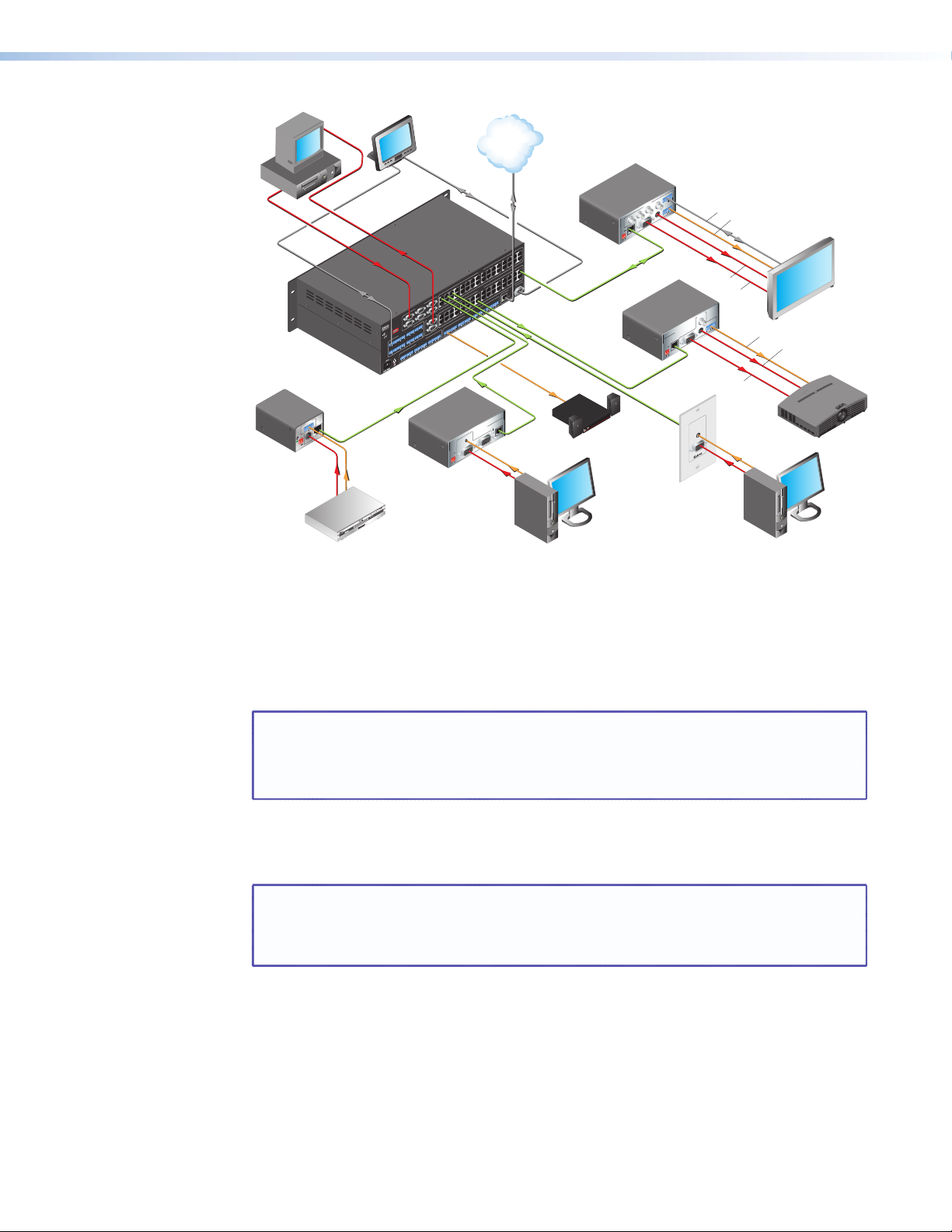
Figure 1. Typical MTPX Plus Twisted Pair Matrix Switcher Application
Flat Panel Display
Audio
S-video
Projector
PC
Additionally, some inputs feature 15-pin HD and 5-pole 3.5 mm captive screw input
connectors for local RGB (VGA) and stereo audio inputs without an MTP transmitter. Some
outputs feature 15-pin HD output connectors and 5-pole 3.5 mm captive screw ports for
local RGB (VGA) and mono audio output without an MTP receiver. The local input and
output 15-pin HD connectors can also support HD-YUV video, YUV video, S-video, and
composite video.
NOTE: For most switchers, the local inputs are an option for use in place of the TP
input (input 1 can be either on the local connectors or the TP connector, for
example).
For the MTPX Plus 128, four inputs are local only and eight inputs are TP only.
When audio is part of the TP input signal, the audio switching can either be linked with the
video (audio follow) or be independent of the video (audio breakaway). Adjustable input
audio gain and attenuation compensates for level differences between audio inputs.
NOTE: For low resolution MTPs (S-video and composite video) on the TP inputs, the
MTPX Plus audio circuits are compatible only with the newer generation,
mono audio models. See your MTP transmitter/ receiver and refer to the
associated manual to determine which MTP models you have.
The matrix switcher can be remotely controlled via its rear panel Remote port
(RS-232/RS-422 for most models, RS-232 only for MTPX Plus 128) and its front panel
Configuration port (RS-232 for most models, USB port for MTPX Plus 128) using either
Extron Windows®-based Matrix Switchers Control Program or the Simple Instruction Set
(SIS™). The SIS is a set of basic ASCII code commands that provides control through a
control system or PC without programming long, obscure strings of code.
MTPX Plus Series • Introduction 2
Page 9

The switcher can be operated remotely by any of the following when that device is
connected to either MTPX Plus serial port:
• A control system
• A PC
• An Extron MKP 2000 remote control panel
• An Extron MKP 3000 remote control panel
For some outputs (most matrix sizes) or all outputs (MTPX Plus 128), bidirectional passthrough RS-232 signals from a dedicated source (rather than from the selected input) can
be directly inserted into the signal set routed to the TP output. You can even route RS-232
on a link that is normally audio, such as to an MTP U R 15HD RSA SEQ receiver, which can
autodetect whether its signal input includes an audio component or an RS-232 component.
The matrix switchers are housed in metal enclosures. Most models have mounting flanges
for standard 19-inch racks built into the enclosure. The MTPX Plus 128 includes a kit for rack
mounting.
The switcher has an internal 100 VAC to 240 VAC, 50-60 Hz, 30 watt power supply that
provides worldwide power compatibility.
The MTPX Plus switcher has a minimum bandwidth of 300 MHz (-3 dB).
The switchers can also switch RGBS, RGsB, RsGsBs, HDTV, component video, S-video, and
composite video.
MTPX Plus Series • Introduction 3
Page 10

TP Cable Advantages
Twisted pair cable is much smaller, lighter, more flexible, and less expensive than coaxial
cable. These TP products make cable runs simpler and less cumbersome. Termination of the
cable with RJ-45 connectors is simple, quick, and economical.
CAUTION: Do not connect this device to a computer data or telecommunications
network.
Transmission distances
The maximum distances are determined by the frequency and resolution of the video signal
being routed and by which MTPX Plus inputs and outputs (TP or local) are in the full (video
source to display) routing path. The tables on the following pages specify the recommended
maximum transmission distances using Extron Enhanced Skew-Free™ A/V UTP cable or UTP
CAT 5, 5e, or 6 cable, terminated with RJ-45 connectors.
NOTES: • For all three tables, the minimum TP cable length should be 25 feet (7.5 m).
• RS-232 serial communications can be sent up to 1,000 feet (300 m) from
the MTP transmitter output (or RS-232 output insert) to the MTP receiver TP
input.
• It is possible to exceed the recommended distances; however, image quality
may be reduced.
• Daisy-chaining MTPX units by connecting a TP output from one matrix
switcher to the TP input of a second matrix switcher is not recommended.
Daisy chaining in this manner can lead to excessive video smearing.
• The transmitters, receivers, and matrix switcher are designed for and perform
best with Extron Enhanced Skew-Free A/V cable terminated in accordance
with the TIA/EIA T 568A wiring standard. CAT 5, 5e, and 6 cables are
acceptable, but less preferable. We also recommend the use of preterminated
and tested cables. Cables terminated on site should be tested before use to
ensure that they comply with Category 5 specifications.
• Daisy-chaining MTPX units by connecting a TP output from one matrix
switcher to the TP input of a second matrix switcher is not recommended.
Daisy chaining in this manner can lead to excessive video smearing.
• The recommendations shown in the tables apply equally for a transmission
line that consists of a single transmitter, the switcher, and receiver and for a
transmission line that encompasses a transmission daisy chain. For example,
the maximum suggested output range (MTPX Plus TP output to MTP receiver)
for 1024 x 768 video is 450 feet (135 m) (table 1 [2]) or 500 feet (150 m)
(table 2 [4]), whether the transmission line consists of the switcher and a
single receiver or the switcher and three daisy-chained receivers. This range
can be extended to 500 feet or 550 feet if the output is one that has the
Pre-Peak function and the function is turned on.
• For daisy-chained units, the first receiver in the chain should be at least
50 feet (15 m) from the switcher when the Pre-Peak feature is on.
• For daisy-chained units, any receiver in the chain closer than 350 feet (105 m)
may experience some form of over-peaking when the Pre-Peak switch is on.
An overpeaked image may appear bloomed.
MTPX Plus Series • Introduction 4
Page 11
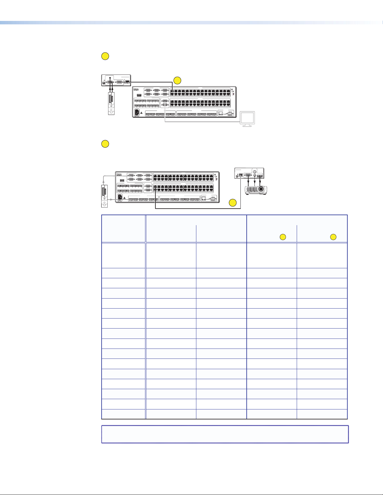
Table 1. Recommended maximum TP transmission distances at 60 Hz,
MTP Receiver
1
MTP transmitter to switcher when the display is on the MTPX Plus local (VGA)
output
AUDIO
MTP T 15HD A
PRE-PEAK
POWER
12V
.5A MAX
INPUT
MTP Transmitter
ON
OFF
OUTPUT
MONITOR
TxRx1TxRx2TxRx3TxRx4TxRx5TxRx6TxRx7TxRx
TxRx9TxRx10TxRx11TxRx12TxRx13TxRx14TxRx15TxRx
LOCAL INPUTS
1
INPUT
SELECT
LOCAL
456
RJ-45
RS-232 OUTPUT INSERTION
3.2A MAX
LR1LR2LR3LR4LR5LR6LR1LR2LR3LR4LR5LR6LR7LR
1234 5678 910111213141516
213
17 18 19 20 21 22 23 24 25 26 27 28 29 30 31 32
LOCAL OUTPUTS OUTPUTS
8
1234 5678 910111213141516
1
16
2
17 18 19 20 21 22 23 24 25 26 27 28 29 30 31 32
INPUTS
MONO AUDIO OUTPUTSAUDIO INPUTS
8
LISTED
1T23
®
US
I.T.E.
CONTROL
ETHERNET
RESET
ACT
LINK
— or —
2
Switcher to MTP receiver when the video source is on the MTPX Plus local
(VGA) input
OUTPUTS
LOCAL INPUTS
INPUT
SELECT
LOCAL
456
RJ-45
RS-232 OUTPUT INSERTION
TxRx1TxRx2TxRx3TxRx4TxRx5TxRx6TxRx7TxRx
TxRx9TxRx10TxRx11TxRx12TxRx13TxRx14TxRx15TxRx
3.2A MAX
LR1LR2LR3LR4LR5LR6LR1LR2LR3LR4LR5LR6LR7LR
1234 5678 910111213141516
213
17 18 19 20 21 22 23 24 25 26 27 28 29 30 31 32
LOCAL OUTPUTS OUTPUTS
8
1234 5678 910111213141516
1
16
2
17 18 19 20 21 22 23 24 25 26 27 28 29 30 31 32
INPUTS
MONO AUDIO OUTPUTSAUDIO INPUTS
8
LISTED
1T23
®
US
I.T.E.
CONTROL
ETHERNET
RESET
ACT
LINK
MTP U R A
POWER
VID
12V
0.5A MAX
MONO AUDIO
L
R
Y/C
RGB
INPUT
2
Video format Sending unit Pre-Peak Maximum distance
Off On High
quality
1
Variable
quality
2
Component,
S-video,
<300' (90 m) >350' (105 m) 800' (285 m) 1,000' (300 m)
Composite
640 x 480 <300' (90 m) >350' (105 m) 700' (215 m) 750' (230 m)
800 x 600 <300' (90 m) >350' (105 m) 550' (170 m) 650' (200 m)
1024 x 768* <300' (90 m) >350' (105 m) 500' (150 m) 600' (185 m)
1280 x 960* <300' (90 m) >350' (105 m) 400' (120 m) 500' (150 m)
1280 x 1024* <250' (75 m) >300' (90 m) 350' (105 m) 450' (135 m)
1360 x 765 <250' (75 m) >300' (90 m) 400' (120 m) 500' (150 m)
1365 x 768 <250' (75 m) >300' (90 m) 400' (120 m) 450' (135 m)
1366 x 768 <250' (75 m) >300' (90 m) 400' (120 m) 450' (135 m)
1440 x 900 <250' (75 m) >300' (90 m) 350' (105 m) 400' (120 m)
1400 x 1050 <250' (75 m) >300' (90 m) 350' (105 m) 400' (120 m)
1600 x 1200* <250' (75 m) >300' (90 m) 300' (90 m) 450' (135 m)
1920 x 1200 <250' (75 m) >300' (90 m) 300' (90 m) 400' (120 m)
HDTV 720p <250' (75 m) >300' (90 m) 400' (120 m) 500' (150 m)
HDTV 1080i <250' (75 m) >300' (90 m) 300' (90 m) 400' (120 m)
HDTV 1080p <250' (75 m) >300' (90 m) 300' (90 m) 400' (120 m)
NOTE: Resolutions marked with an asterisk (*) in this table have the same range
specifications at 75 Hz.
MTPX Plus Series • Introduction 5
Page 12
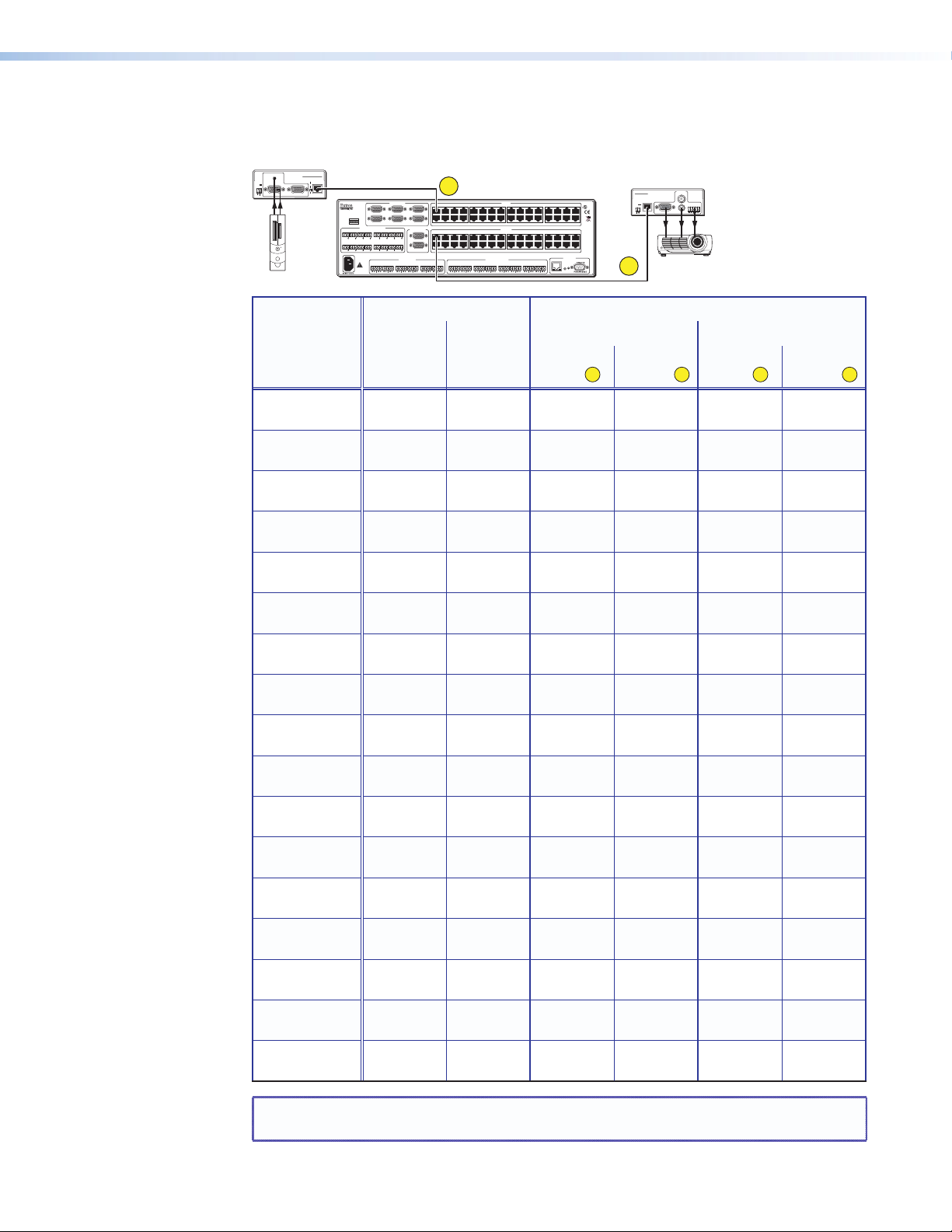
Table 2. Recommended maximum TP transmission distances at 60 Hz, —
MTP Transmitter
transmitter to receiver using MTPX Plus TP inputs and outputs
AUDIO
MTP T 15HD A
POWER
12V
.5A MAX
PRE-PEAK
ON
OFF
OUTPUT
INPUT
MONITOR
TxRx1TxRx2TxRx3TxRx4TxRx5TxRx6TxRx7TxRx
TxRx9TxRx10TxRx11TxRx12TxRx13TxRx14TxRx15TxRx
LOCAL INPUTS
INPUT
SELECT
3.2A MAX
213
LOCAL
456
RJ-45
RS-232 OUTPUT INSERTION
16
LR1LR2LR3LR4LR5LR6LR1LR2LR3LR4LR5LR6LR7LR
3
1234 5678 910111213141516
17 18 19 20 21 22 23 24 25 26 27 28 29 30 31 32
LOCAL OUTPUTS OUTPUTS
8
1234 5678 910111213141516
1
2
17 18 19 20 21 22 23 24 25 26 27 28 29 30 31 32
MONO AUDIO OUTPUTSAUDIO INPUTS
INPUTS
CONTROL
ETHERNET
8
RESET
ACT
LINK
LISTED
1T23
®
US
I.T.E.
MTP Receiver
MTP U R A
0.5A MAX
OUTPUTS
POWER
VID
12V
Y/C
RGB
INPUT
4
MONO AUDIO
L
R
Video format MTPX Pre-Peak Maximum distance
High quality Variable quality
Off On MTPX
input
Component,
S-video
Composite <300'
640 x 480 <300'
800 x 600 <300'
1024 x 768* <300'
1280 x 960* <300'
1280 x 1024* <250'
1360 x 765 <250'
1365 x 768 <250'
1366 x 768 <250'
1440 x 900 <250'
1400 x 1050 <250'
1600 x 1200* <250'
1920 x 1200 <200'
HDTV 720p <250'
HDTV 1080i <200'
HDTV 1080p <200'
<300'
(90 m)
(90 m)
(90 m)
(90 m)
(90 m)
(90 m)
(75 m)
(75 m)
(75 m)
(75 m)
(75 m)
(75 m)
(75 m)
(60 m)
(75 m)
(60 m)
(60 m)
>350'
(105 m)
>350'
(105 m)
>350'
(105 m)
>350'
(105 m)
>350'
(105 m)
>350'
(105 m)
>300'
(90 m)
>300'
(90 m)
>300'
(90 m)
>300'
(90 m)
>300'
(90 m)
>300'
(90 m)
>300'
(90 m)
>250'
(75 m)
>300'
(90 m)
>250'
(75 m)
>250'
(75 m)
700'
(215 m)
700'
(215 m)
550'
(170 m)
500'
(150 m)
450'
(135 m)
350'
(105 m)
350'
(105 m)
350'
(105 m)
350'
(105 m)
350'
(105 m)
350'
(105 m)
350'
(105 m)
300'
(90 m)
300'
(90 m)
400'
(120 m)
300'
(90 m)
300'
(90 m)
3
MTPX
output
700'
(215 m)
700'
(215 m)
600'
(185 m)
500'
(150 m)
450'
(135 m)
350'
(105 m)
350'
(105 m)
350'
(105 m)
350'
(105 m)
350'
(105 m)
300'
(90 m)
300'
(90 m)
300'
(90 m)
250'
(75 m)
400'
(120 m)
250'
(75 m)
250'
(75 m)
MTPX
4
input
3
700'
(215 m)
750'
(230 m)
600'
(185 m)
600'
(185 m)
550'
(170 m)
450'
(135 m)
450'
(135 m)
500'
(150 m)
450'
(135 m)
450'
(135 m)
400'
(120 m)
400'
(120 m)
450'
(135 m)
400'
(120 m)
500'
(150 m)
400'
(120 m)
400'
(120 m)
MTPX
output
800'
(245 m)
750'
(230 m)
650'
(200 m)
600'
(185 m)
550'
(170 m)
450'
(135 m)
450'
(135 m)
500'
(150 m)
450'
(135 m)
450'
(135 m)
400'
(120 m)
400'
(120 m)
450'
(135 m)
400'
(120 m)
500'
(150 m)
400'
(120 m)
400'
(120 m)
4
NOTE: Resolutions marked with an asterisk (*) in this table have the same range
specifications at 75 Hz.
MTPX Plus Series • Introduction 6
Page 13
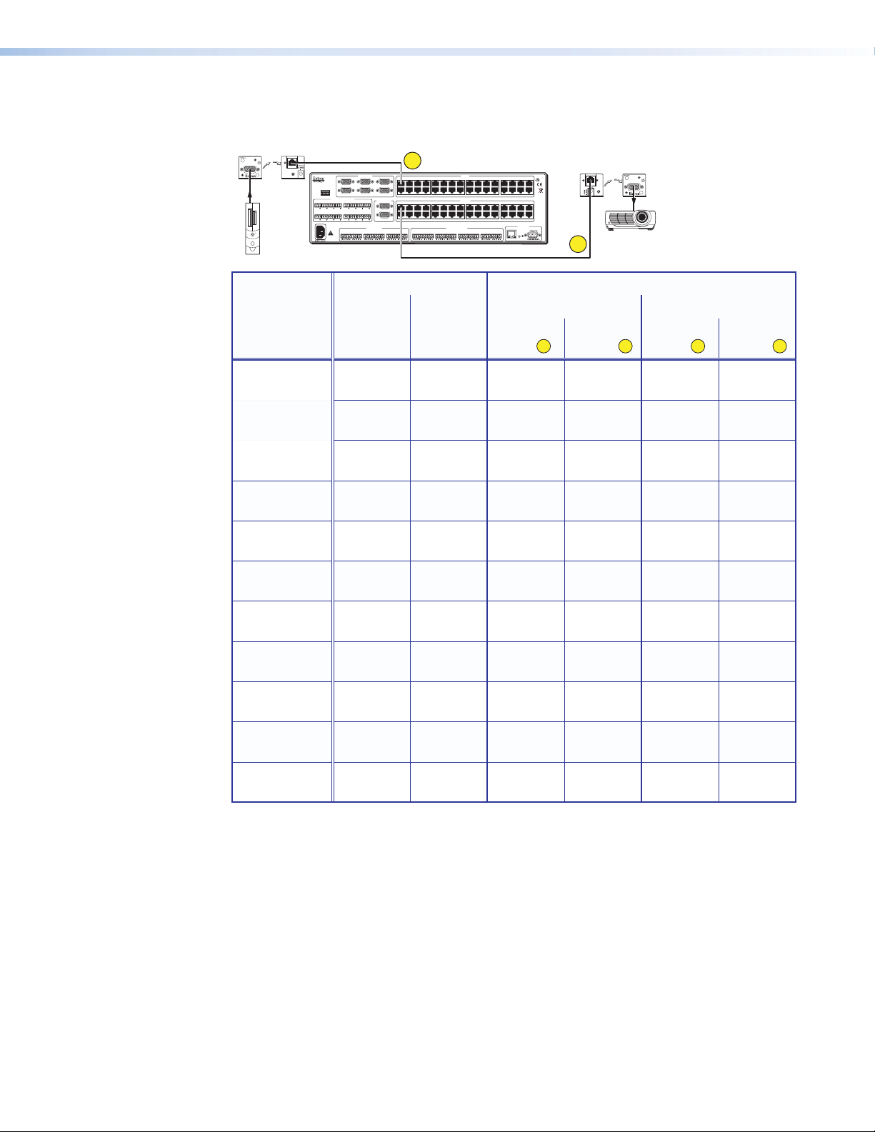
Table 3. Recommended maximum TP transmission distances at 60 Hz, —
VTT Transmitter
VTT transmitter to VTR receiver using MTPX TP inputs and outputs
POWER
VIDEO INPUT
TX
9VDC-12VDC
500mA
TxRx1TxRx2TxRx3TxRx4TxRx5TxRx6TxRx7TxRx
TxRx9TxRx10TxRx11TxRx12TxRx13TxRx14TxRx15TxRx
3.2A MAX
LOCAL INPUTS
3
INPUT
SELECT
LOCAL
456
RJ-45
RS-232 OUTPUT INSERTION
LR1LR2LR3LR4LR5LR6LR1LR2LR3LR4LR5LR6LR7LR
1234 5678 910111213141516
213
17 18 19 20 21 22 23 24 25 26 27 28 29 30 31 32
LOCAL OUTPUTS OUTPUTS
8
1234 5678 910111213141516
1
16
2
17 18 19 20 21 22 23 24 25 26 27 28 29 30 31 32
MONO AUDIO OUTPUTSAUDIO INPUTS
INPUTS
CONTROL
ETHERNET
8
RESET
ACT
LINK
LISTED
1T23
®
US
I.T.E.
VTR Receiver
RX
VIDEO OUTPUT
9VDC-12VDC
500mA
4
POWER
Video format MTPX Pre-Peak Maximum distance
High quality Variable quality
Off On MTPX
3
input
640 x 480 <300'
(90 m)
800 x 600 <250'
(75 m)
1024 x 768 <150'
(45 m)
1280 x 960 <150'
(45 m)
1280 x 1024 <150'
(45 m)
1360 x 765 <150'
(45 m)
1365 x 768 <150'
(45 m)
1366 x 768 <150'
(45 m)
1440 x 900 <150'
(45 m)
1400 x 1050 <150'
(45 m)
1600 x 1200 <100'
(30 m)
>350'
(105 m)
>300'
(90 m)
>200'
(60 m)
>200'
(60 m)
>200'
(60 m)
>200'
(60 m)
>200'
(60 m)
>200'
(60 m)
>200'
(60 m)
>200'
(60 m)
>150'
(45 m)
400'
(120 m)
350'
(105 m)
300'
(90 m)
250'
(75 m)
250'
(75 m)
250'
(75 m)
250'
(75 m)
250'
(75 m)
200'
(60 m)
200'
(60 m)
200'
(60 m)
MTPX
output
350'
(105 m)
300'
(90 m)
300'
(90 m)
200'
(60 m)
200'
(60 m)
200'
(60 m)
200'
(60 m)
200'
(60 m)
200'
(60 m)
200'
(60 m)
150'
(45 m)
4
MTPX
input
400'
(120 m)
400'
(120 m)
350'
(105 m)
300'
(90 m)
300'
(90 m)
300'
(90 m)
300'
(90 m)
300'
(90 m)
250'
(75 m)
250'
(75 m)
250'
(75 m)
3
MTPX
output
400'
(120 m)
350'
(105 m)
350'
(105 m)
300'
(90 m)
250'
(75 m)
250'
(75 m)
250'
(75 m)
250'
(75 m)
250'
(75 m)
250'
(75 m)
200'
(60 m)
4
MTPX Plus Series • Introduction 7
Page 14

Features
Skew equalization
Skew exists between wire pairs when the physical length of one wire pair is different from
another. Skew affects the displayed image when the differential length between wire pairs
exceeds 2 feet. This causes the timing of the red, green, and blue video signals to appear out
of alignment (horizontal registration errors). The signals transmitted on the shortest pair are
shifted to the left if you are viewing white lines on a black background. A white vertical line
on a black field can appear as individual red, green, and blue lines that are close together.
The signal transmitted on the shortest wire pair leads the other colors and appears to the left
on the display. As the transmission cable length increases, the skew effect increases.
The MTPX Plus has a skew equalizer function that is available using SIS, the Matrix Switchers
Control Program, or built-in HTML page control. The skew function provides separate time
delay circuits on the red, green, and blue video lines on the inputs and the outputs. Each
time delay circuit can be independently adjusted, from 0 to 62 nanoseconds, to properly
align the red, green, and blue video signals on the displayed image. When correctly set, the
red, green, or blue video signal on the shortest wire pair is delayed to properly converge the
displayed video image.
UTP cable test equipment measures and reports wire pair length. The report on the various
pair lengths can be used to properly equalize pair skew. If UTP cable test measurement
cannot be done, pair skew can still be equalized by viewing a test pattern with a critical eye.
Examine the test pattern for loss of horizontal registration and, through a process of trial
and error, equalize any pair skew.
Twisted pair inputs and outputs — The switchers input and output TP signals on
female RJ-45 connectors.
NOTE: For low resolution MTPs (S-video and composite video) on the TP inputs, the
MTPX Plus audio circuits are compatible only with the newer generation,
mono audio models. See your MTP transmitter/ receiver and refer to the
associated manual to determine which MTP models you have.
Local video inputs and outputs — The switchers directly input and output RGBHV or
RGBS (VGA) video on 15-pin HD connectors. They can also input and output RGsB, RsGsBs,
component/HDTV, S-video, or composite video.
Local audio inputs — The switchers directly input balanced or unbalanced stereo audio
on 3.5 mm, 5-pole captive screw terminals.
Audio input gain/attenuation — The volume of each audio input can be adjusted so
there are no noticeable volume differences between sources. You can set the input level of
audio gain or attenuation (-18 dB to +24 dB) via the front panel or via serial port control.
Audio output volume — The volume of each audio signal that is output on the 5-pole,
3.5 mm captive screw input connectors can be displayed and adjusted through a range of
full output to complete silence. Adjustments can be made from the front panel or remote
control.
MTPX Plus Series • Introduction 8
Page 15

Switching flexibility — The switcher provides individually buffered, independent, matrix
switched outputs with audio follow and audio breakaway.
• Tie any input to any or all outputs.
• Quick multiple tie — Multiple inputs can be switched to multiple outputs
simultaneously. This allows all displays (outputs) to change from source to source at
the same time.
• Audio follow — Audio can be switched with its corresponding video input via front
panel control or via serial port remote control.
• Audio breakaway — Audio can be broken away from its corresponding video
signal. This feature allows any audio signal to be tied to one or all outputs in any
combination with or without an accompanying video signal. Audio breakaway
switching can be done via front panel control or via serial port remote control.
Operational flexibility — Operations such as input/output selection, setting of presets,
and adjustment of audio levels can be performed using the front panel or via either serial
port. The serial ports allow remote control via a PC or a control system.
• Front panel controls — The front panel controls support input and output
selection, preset creation and selection, audio gain and attenuation, and volume
control. The front panel features slots for labels that can identify each input and
output with text or graphics.
• Matrix Switchers Control Program — For serial port remote control from a PC,
the Extron Windows-based Matrix Switchers Control Program provides a graphical
interface and drag-and-drop/point-and-click operation. The Matrix Switchers Control
Program also has an emulation mode that lets you create a switcher configuration file
at the home office and then download it for use by the switcher on site.
• Simple Instruction Set (SIS) — The remote control protocol uses the Extron SIS
for easy programming and operation.
• Remote control panels and keypads — The matrix switchers are remote
controllable, using the optional MKP 2000 and MKP 3000 remote control keypads.
These remote control devices are easy to use and provide tactile buttons for quick
selection. Each MKP can be used for input-to-output switching or one-touch switching
for a particular output. The MKP 3000 also can be used for selection of global presets.
EDID Minder (MTPX Plus 128 only) — Captures and stored EDID information,
continuously making it available to all local inputs. EDID minder has two operating modes:
• Automatic (default) — Captures EDID for displays connected to the local outputs
and provides data to the appropriate local inputs.
• User Assigned Mode — Rates from EDID table can be selected and assigned to
any input. EDID file for the display connected to output 1 can be stored in the EDID
table (4 user assigned locations available).
Upgradeable firmware — The firmware that controls all switcher operations can be
upgraded in the field via either serial port, without taking the switcher out of service.
Firmware upgrades are available for download on the Extron website, www.extron.com,
and can be installed using the Matrix Switchers Control Program.
Labeling — The Extron button label software is shipped with every Extron matrix switcher.
You can create labels to place above the front panel input buttons and below the output
buttons, with names, alphanumeric characters, or color bitmaps for easy and intuitive input
and output selection. Alternatively, labels can be made with any Brother
®
P-Touch™ or
comparable labeler.
Global memory presets — 32 global memory presets are a time-saving feature that
lets you set up and store input/output configurations in advance. You can then recall those
configurations, when needed, with a few simple steps on the front panel.
MTPX Plus Series • Introduction 9
Page 16

Rack mounting — The 1U high (MTPX Plus 128), 2U high (other matrix sizes 1616
and smaller), or 3U high (matrix sizes 1632 and larger) enclosure is rack mountable in any
conventional 19-inch wide wide rack. The 2U and 3U enclosures are mountable without
extra hardware. The 1U enclosure is rack mountable using the provided mounting kit.
Three front panel security lockout modes (Executive modes) — If a matrix
switcher is installed in an open area, where operation by unauthorized personnel may be
a problem, either of two security lockout modes can be implemented (the third mode is
unlocked). When a front panel lockout mode is enabled, a special button combination or
SIS command is required to unlock the front panel controls and make the front panel fully
operational.
Power — The 100 VAC to 240 VAC internal power supply provides worldwide power
compatibility.
MTPX Plus Series • Introduction 10
Page 17
Installation
This sections details the installation of the MTPX Plus Matrix Switchers, including:
• Mounting the Switcher
• Rear Panel Cabling and Settings
• Front Panel Configuration Port
Mounting the Switcher
CAUTION: Installation and service must be performed by authorized personnel only.
Detailed mounting instructions can be found in the “Reference Information“ section at
the end of this guide. The MTPX Plus switchers are housed in a 1U high (MTPX Plus 128),
2U high (other matrix sizes 1616 and smaller), or 3U high (matrix sizes 1632 and larger)
metal enclosures. The 1U enclosure is rack mountable using the provided MBD 149
Through-desk and rack mounting kit (part number 70-077-03). The 2U and 3U enclosures
are mountable without extra hardware.
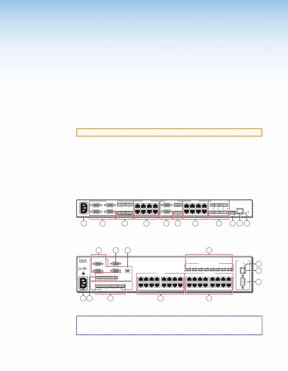
Rear Panel Cabling and Settings
Figure 2 shows the rear panel of the MTPX Plus 128.
100-240V 0.8A
50-60Hz
Figure 2. MTPX Plus 128 Twisted Pair Matrix Switcher
Figure 3 shows the rear panel of the MTPX Plus 1616.
LOCAL INPUTS
LISTED
1T23
I.T.E.
1.6A MAX
13
3
Figure 3. MTPX Plus 1616 Twisted Pair Matrix Switcher
NOTE: The MTPX Plus 816 and MTPX Plus 168 are housed in the same 2U enclosure,
1
3
LOCAL INPUTS
R1
R2
L
L
2
4
R3
R4
L
L
7 4
LOCAL OUTPUT
1
2
AUDIO
AUDIO
1
2
R
R
L
L
MONO AUDIO OUTPUTS
RGB
RGB
LOCAL
ON
3
123
RJ - 45
INPUT
SELECT
3
4
R
R
L
RGB
RGB
L
but have fewer input connectors (8 x 16 matrix) or output connectors (16 x 8
matrix) to accommodate their smaller matrix sizes.
INPUTS
5 678
9101112
1234 5678
910 11 12 13 14 15 16
INPUTS
LOCAL OUTPUTS
1
2
OUTPUTS
R1
L
1234
R2
L
5678
RS - 232 OUTPUT INSERT
12345678
Tx Rx
Tx Rx
Tx Rx
1234 5678
910 11 12 13 14 15 16
58
Tx Rx
OUTPUTS
612
RS-232 OUTPUT INSERT
1234
Tx Rx
Tx Rx Tx Rx
5678
568732 1
Tx Rx
Tx Rx
RESET
LAN
Tx Rx
REMOTE
RS-232
Tx Rx
ACT
LINK
101113 9
CONTROL
Tx Rx
RESET
Tx Rx
ETHERNET
REMOTE
LINK
ACT
RS-232/RS-422
12
11
10
MTPX Plus Series • Installation 11
Page 18
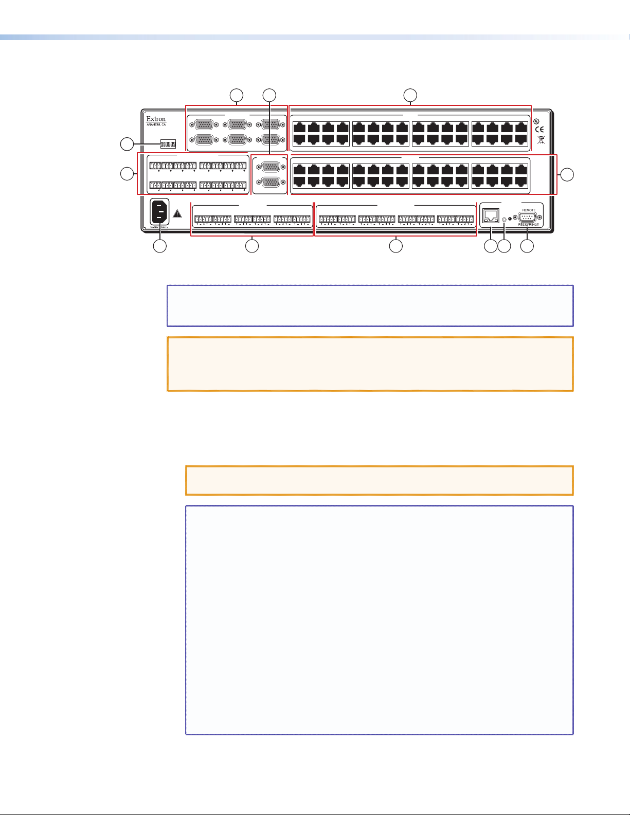
Figure 4 shows the rear panel of the MTPX Plus 3232.
2 17
LOCAL INPUTS
INPUT
SELECT
4
4
5
LOCAL
RJ-45
Tx Rx1Tx Rx2Tx Rx3Tx Rx4Tx Rx5Tx Rx6Tx Rx7Tx Rx
Tx Rx9Tx Rx10Tx Rx11Tx Rx12Tx Rx13Tx Rx14Tx Rx15Tx Rx
3.2A MAX
3.2A MAX
456
RS-232 OUTPUT INSERTION
LR1LR2LR3LR4LR5LR6LR1LR2LR3LR4LR5LR6LR7LR
13 11 12 10
213
LOCAL OUTPUTS OUTPUTS
8
16
3 8
1234 5678 910111213141516
17 18 19 20 21 22 23 24 25 26 27 28 29 30 31 32
1234 5678 910111213141516
1
2
17 18 19 20 21 22 23 24 25 26 27 28 29 30 31 32
INPUTS
INPUTS
MONO AUDIO OUTPUTSAUDIO INPUTS
Figure 4. MTPX Plus 3232 Twisted Pair Matrix Switcher
NOTE: The MTPX Plus 1632 and MTPX Plus 3216 are housed in the same 3U enclosure,
but have fewer input connectors (16 x 32 matrix) or output connectors
(32 x 16 matrix) to accommodate their smaller matrix sizes.
CAUTIONS: • Use Electrostatic discharge (ESD) precautions (that is, be electrically
grounded) when making connections. Electrostatic discharge can damage
equipment, even if you cannot feel, see, or hear it.
• Remove system power before making any connections.
LISTED
1T23
®
US
I.T.E.
6
CONTROL
ETHERNET
8
RESET
ACT
LINK
Signal Inputs
a Inputs (TP) connectors — Connect the TP outputs of compatible MTP or VTT
transmitters to these RJ-45 female connectors.
CAUTION: Do not connect this device to a computer data or telecommunications
NOTES: • Configure the switcher for the appropriate content on the audio/RS-232
• For best results, use a minimum cable length of at least 25 feet (7.5 m)
• RJ-45 termination with CAT 5, CAT 5e, or CAT 6 cable must comply with
RJ-45 termination with Enhanced Skew-Free A/V UTP cable must comply
• For low resolution MTPs (S-video and composite video) on the TP
network.
wire pair (pins 3 and 6) for each TP input (see “Defining the Audio/
RS-232 Wire Pair“ in the “Operation” section). You can also use
SIS commands (see the “Programming Guide” section), the Matrix
Switchers Control Program (see the “Matrix Software“ section), or the
HTML pages (see the “HTML Operation” section).
between the transmitter and the MTPX input and between the MTPX
output and the transmitter.
the TIA/EIA T568A or TIA/EIA T568B wiring standards for all connections.
with TIA/EIA T568A only.
inputs, the MTPX Plus audio circuits are compatible only with the newer
generation, mono audio models. See your MTP transmitter/ receiver and
refer to the associated manual to determine which MTP models you have.
MTPX Plus Series • Installation 12
Page 19
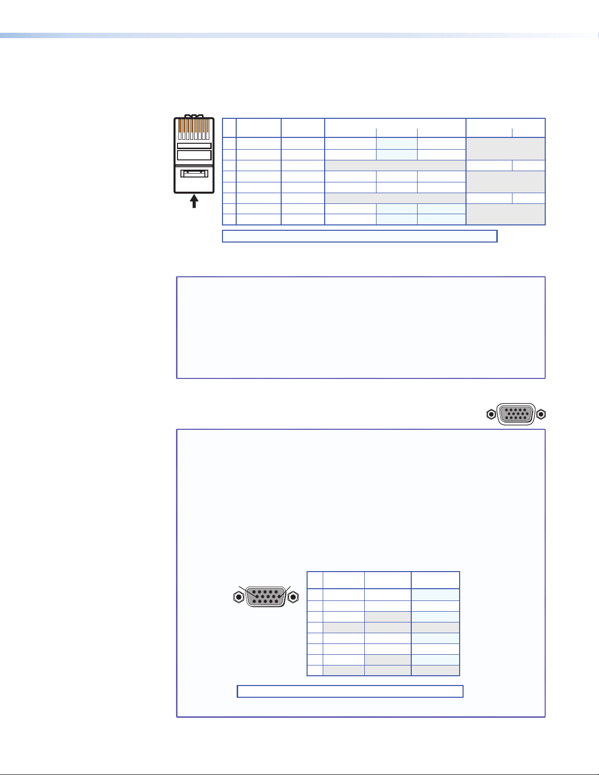
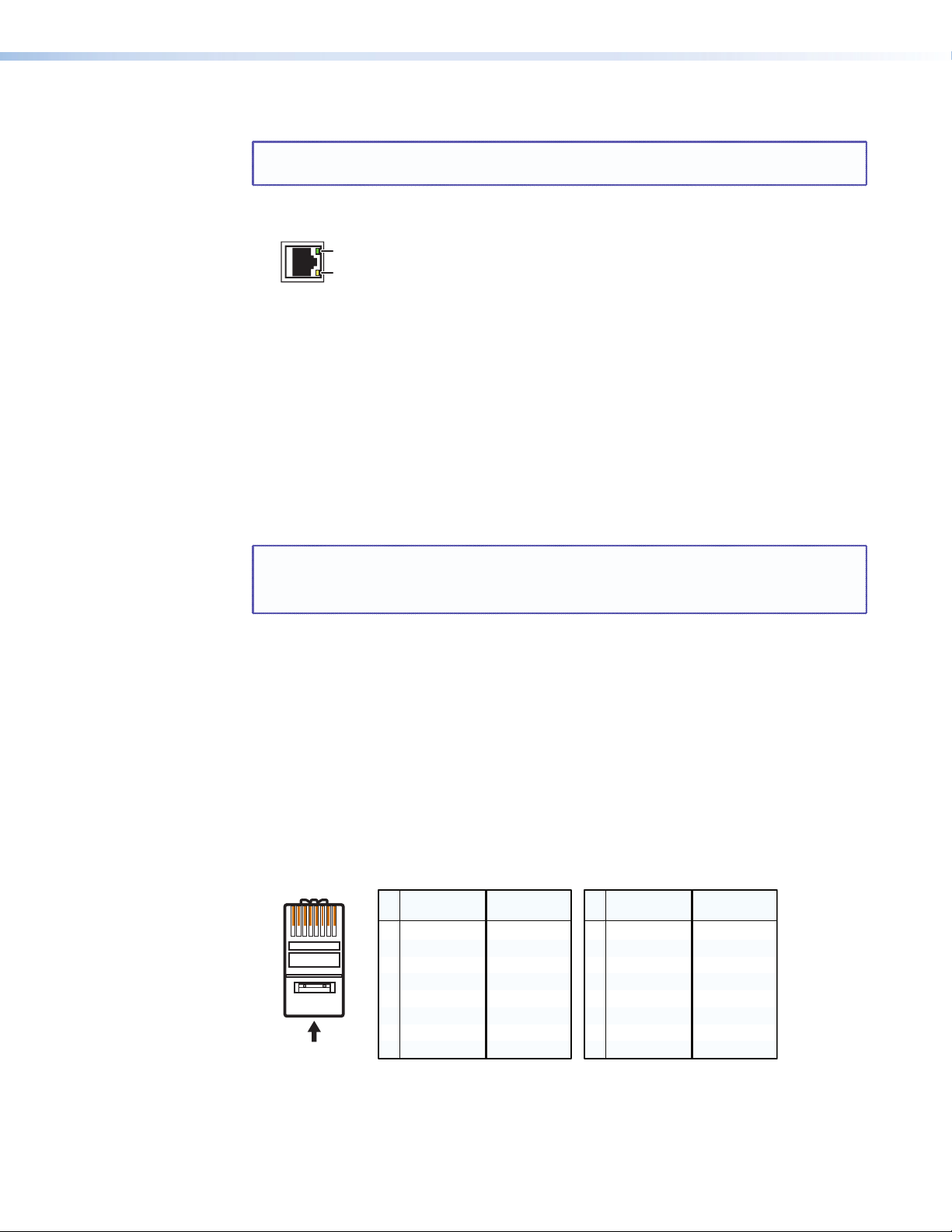
Figure 5 shows the recommended termination of TP cables in accordance with the
RGB
TIA/EIA T568A or TIA/EIA T568B wiring standards. You can use either standard with CAT
5, 5e, or 6 cable, but use the same standard on both ends of the cable.
Pins:
12345678
T568A T568B Video input (via transmitter or local input) Secondary input
S-video
Chroma (C)+
Chroma (C)-
Luma (Y)+
Luma (Y)-
Reserved
Reserved
Stereo audio
Mono audio+
Mono audio-
Insert Twisted
Pair Wires
RJ-45
Connector
Pin
Wire color
1 Red+/V. sync+
White-green
2 Red–/V. sync–
Green
3 RS-232+
White-orange
4
White-blue
5
6 RS-232-
Orange
7 Blue+/H. sync+
White-brown
8 Blue-/H. sync-
Brown
NOTE: If you are using Enhanced Skew-Free A/V cable, use the TIA/EIA T568A standard only.
Wire color
White-orange
Orange
White-green
White-blue
Green
White-brown
Brown
RGB
Green+Blue Blue
Green-
Composite
Reserved
Reserved
Video+
Video-
Reserved
Reserved
Figure 5. TP Cable Termination
NOTE: Enhanced Skew-free A/V cable is not recommended for Ethernet/LAN
applications. This cable is specially designed for compatibility with the
Extron Twisted Pair products that are wired using the TIA/EIA 568A
standard.
The green, brown, and blue pairs of this cable have virtually identical
lengths and should be used to transmit the RGB signals.
The orange pair of this cable has a different length and should not be used
to transmit the RGB signals..
RS-232
b Local Inputs (VGA) connectors — Connect analog computer-
video (RGB) sources to these 15-pin HD female connectors.
NOTES: • The video that is input on this connector, when it is tied to a TP output,
is converted to same type of the proprietary TP signal that is output by
the MTP 15HD transmitters. This allows you to eliminate some of the
transmitters in your system.
• When either the input or output of a tie is local (VGA), Extron
recommends that the MTP output or input be connected by a minimum
of 25 feet (7.5 m) of TP cable to prevent overpeaking.
• The matrix switchers can also input and switch HD component video,
component video, S-video, or composite video by using the appropriate
adapters and the pins show in figure 6. No configuration of the switcher
is required for component or other non-RGB video formats.
51
15 11
Female
* You can input and output additional, genlocked, composite video on these pins.
NOTE: Input only sync signals, no video signals, on the sync pins (13 and 14).
610
Component S-video Composite
Pin
Signal
1
R-Y
2 Video
Y
3
B-Y
4-5
6
R-Y return
7 Video return
Y return
8
B-Y return
9-15
Signal
Chroma (C)
Luma (Y)
Chroma return
Luma return
Signal
Video 2*
Video 3*
Video 2 return*
Video 3 return*
Figure 6. Other Video Formats on a VGA Connector
MTPX Plus Series • Installation 13
Page 20
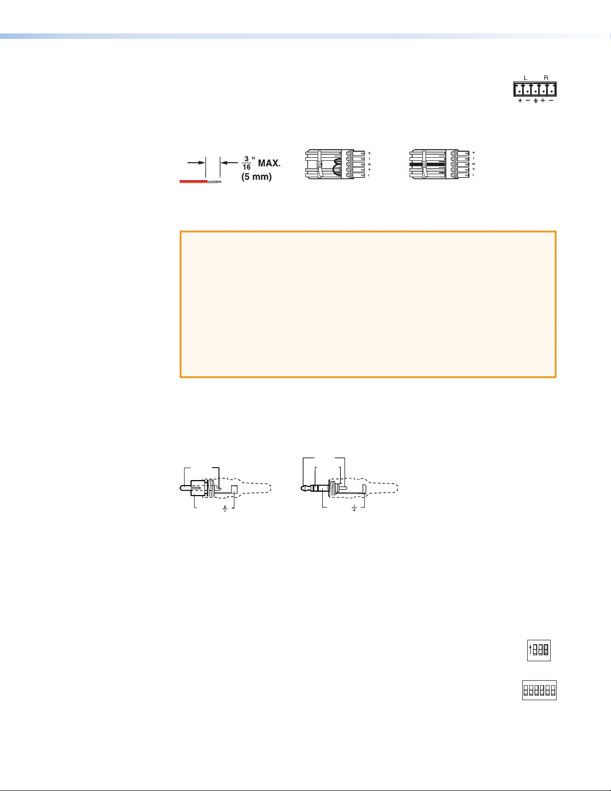
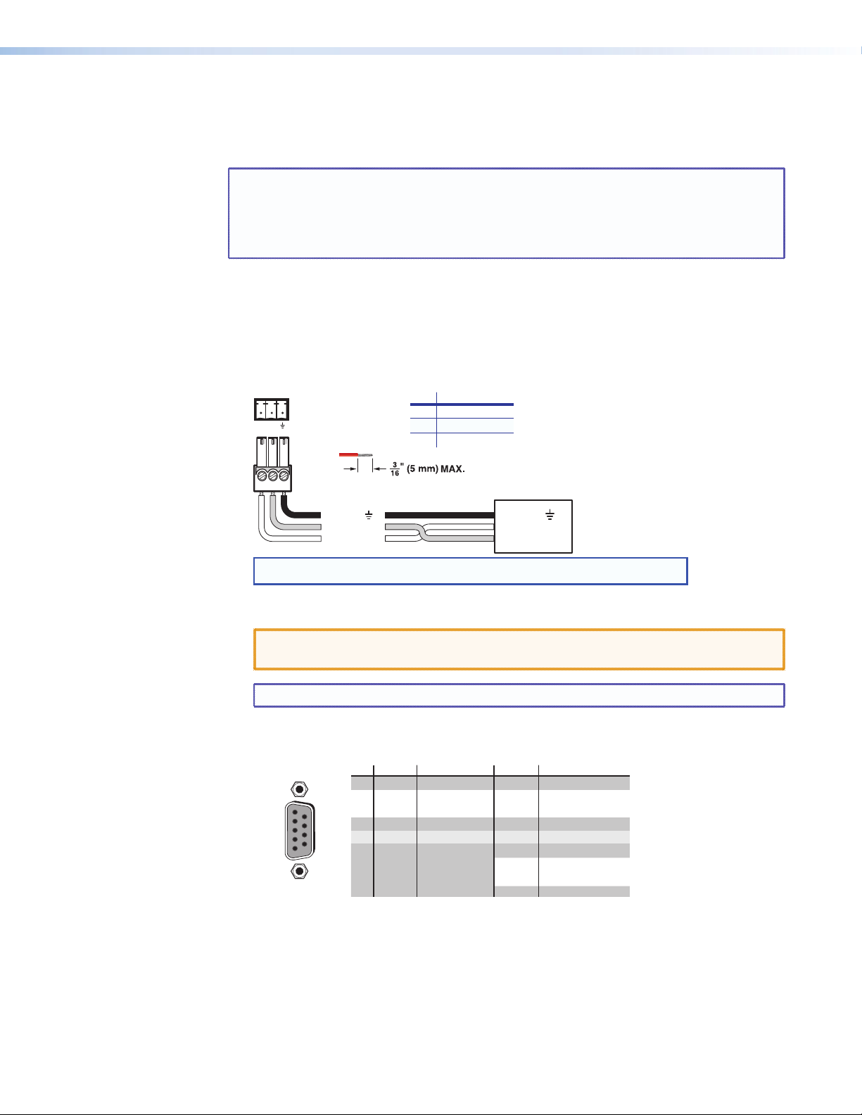
c Audio Inputs (local audio) connectors — Connect balanced or
LR
LR
Unbalanced Stereo Input
Balanced Stereo Input
(high impedance)
(high impedance)
Do not tin the wires!
Ring
Sleeve (s)
Tip
Sleeve
Tip
Sleeve
Tip
Tip
Ring
Tip (+)
Sleeve ( )
Sleeve ( )
Ring (-)
Tip (+)
RCA Connector
3.5 mm Stereo Plug Connector
(balanced)
LOCAL
unbalanced stereo audio inputs to these 3.5 mm, 5-pole captive screw
connectors. Connectors are included with each switcher, but you must
supply the audio cable. See figure 7 to wire a connector for the appropriate
input type and impedance level. Use the supplied tie-wrap to strap the audio cable to
the extended tail of the connector. High impedance is generally over 800 ohms.
Figure 7. Captive Screw Connector Wiring for Audio Inputs
CAUTIONS: • The length of exposed wires is critical. The ideal length is 3/16 inch
(5 mm).
If the stripped section of wire is longer than 3/16 inch, the
•
exposed wires may touch, causing a short circuit.
• If the stripped section of wire is shorter than 3/16 inch, wires can
be easily pulled out even if tightly fastened by the captive screws.
• The captive screw audio connector can easily be inadvertently plugged
partially into one receptacle and partially into an adjacent receptacle.
This misconnection could damage the audio output circuits. Ensure
that the connector is plugged fully and only into the desired input or
output.
A mono audio connector consists of a tip and sleeve. A stereo audio connector consists
of a tip, ring and sleeve. See figure 8 to identify the tip, ring, and sleeve parts of the
connector when you are making connections for the switcher from existing audio
cables. The ring, tip, and sleeve wires are also shown on the captive screw audio
connector diagrams, figure 7 and figure 10.
Figure 8. Typical Audio Connectors
The audio level for each input can be individually set via the front panel or remote
control to ensure that the level on the output does not vary from input to input (see
“Viewing and Adjusting the Input Audio Level“ in the “Operation” section).
You can also use SIS commands (see the “Programming Guide” section), the Matrix
Switchers Control Program (see the “Matrix Software“ section), or the HTML pages
(see the “HTML Operation” section).
d Input Select switches (switchers other than the
MTPX Plus 128) — For inputs 1 through 3 (matrix sizes 1616 and smaller,
excluding the MTPX Plus 128) or inputs 1 through 6 (matrix sizes 1632 and
larger), set these DIP switches to the Local (up) position to select the local
(RGB video and audio) input. Set the DIP switches to the RJ-45 (down) position
to select the MTP input.
ON
123
RJ - 45
INPUT SELECT
LOCAL
RJ-45
MTPX Plus Series • Installation 14
Page 21
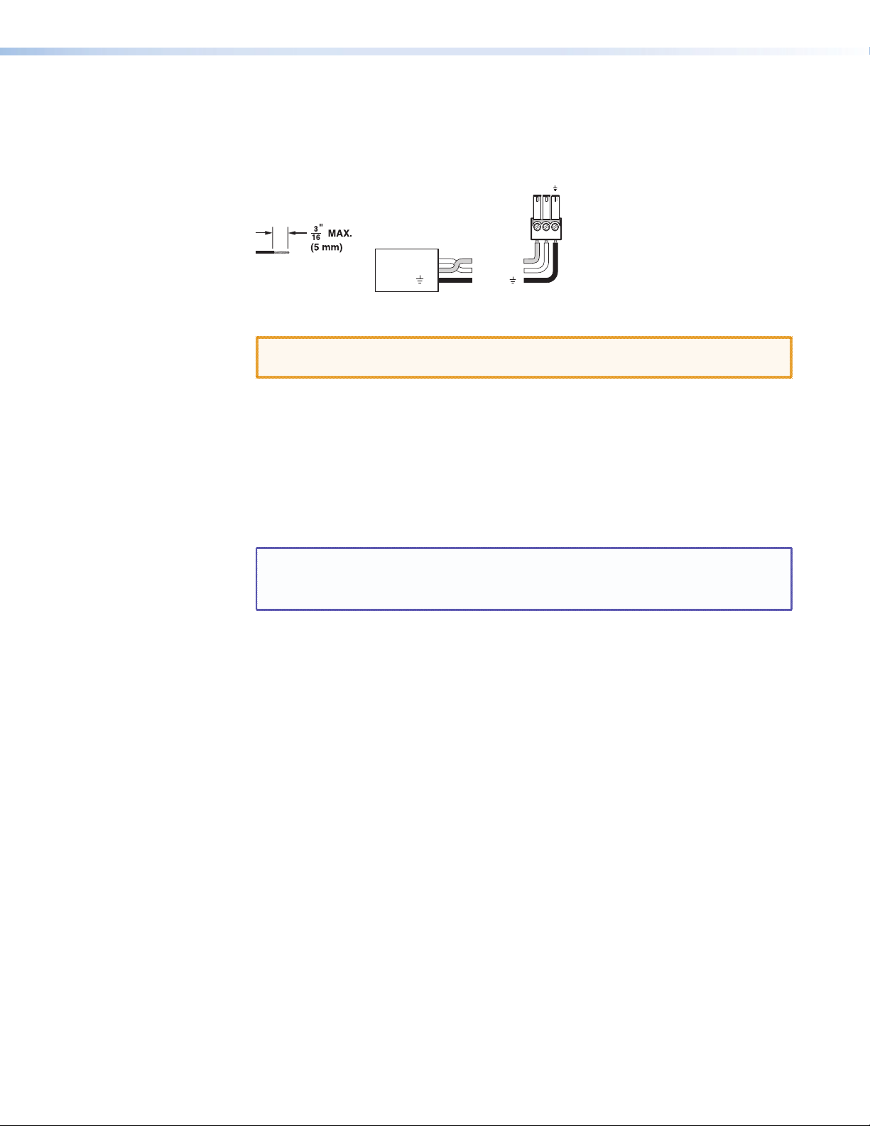
RS-232 Output Inserts
RxTx
e RS-232 Output Insert connectors — For bidirectional RS-232 data that is routed
to a specific (unswitchable) TP output, connect a serial device to one of these 3.5 mm,
3-pole captive screw connectors. Figure 9 shows how to wire the connectors.
Do not tin the wires!
Figure 9. RS-232 Output Insert Wiring
CAUTION: The length of exposed wires is critical (see the CAUTIONS on page 14 for
For the RS-232 Output Insert to be available on the TP output, the insert must be
enabled via an SIS command (see the “Programming Guide” section), the Matrix
Switchers Control Program (see the “Matrix Software“ section), or an MTPX Plus
HTML page (see the “HTML Operation” section).
Each RS-232 output insertion is dedicated to the output with that number; for example,
RS-232 Output Insert 1 is always routed to the Output 1 TP connector (when enabled
as described in the note above), RS-232 Output Insert 2 is routed to the Output 2 TP
connector, and so on.
details).
RS-232
Device
Transmit (Tx)
Receive (Rx)
Ground ( )
Bidirectional
Transmit (Tx)
Receive (Rx)
Ground ( )
NOTES: • When an RS-232 output insert is enabled, any content on the
audio/RS-232 wire pair for the TP input tied to that output is disabled.
• The switch time for the RS-232 output insert is 50 ms.
MTPX Plus Series • Installation 15
Page 22

Signal Outputs
f Outputs (MTP) connectors — Connect the TP inputs of compatible MTP or VTR
receivers to these RJ-45 female connectors.
See the Inputs connector (item a) in the “Signal inputs” section, for detailed pin
assignments for the RJ-45 connectors.
CAUTION: Do not connect this device to a computer data or telecommunications
network.
NOTE: For best results, use a cable length of at least 25 feet (7.5 m) between the
TP output connector and the receiver.
g Local Outputs (VGA) connector(s) — Connect one or two RGBHV video displays
to these 15-pin HD female connectors for each output.
Matrix sizes 1616 and smaller (excluding the MTPX Plus 128) have one local video
output.
Matrix sizes 1632 and larger and the MTPX Plus 128 have two local video outputs.
These outputs are always outputs 1 and 2, with the same inputs tied to them as to
TP outputs 1 and 2.
NOTES: • The video that is output on this (these) connector(s) is converted from
the tied proprietary TP input signal or the local (VGA) input. This feature
allows you duplicates of output(s) 1 (and 2) while eliminating the need
for extra receivers.
• When either the output or input of a tie is local (VGA), Extron
recommends that the MTP input or output be connected by a minimum
of 25 feet (7.5 m) of TP cable to prevent overpeaking.
• This connector can also output HD component video, component video,
S-video, or composite video, using the appropriate adapters, if that is
the video format that was input. See figure 6 on page 13 to identify the
pins to use for the various video formats. Also, set the output to no sync
processing (see the Local video output sync polarity SIS commands on
page 83.
MTPX Plus Series • Installation 16
Page 23
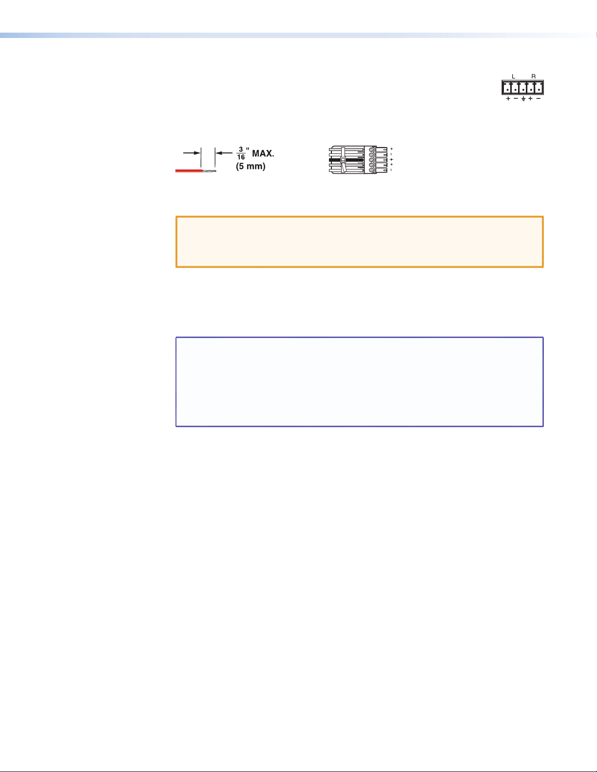
h Mono Audio (local audio) outputs — Connect audio devices, such
as an audio amplifier or powered speakers, to these four or eight 3.5 mm,
5-pole captive screw connectors. These connectors output the selected
unamplified, mono line level audio. See figure 10 to wire an output
connector. Use the supplied tie-wrap to strap the audio cable to the extended tail of the
connector.
Tip
Ring
Sleeve(s)
Tip
Ring
Do not tin the wires!
Mono Output
Figure 10. Captive Screw Connector Wiring for Audio Output
CAUTIONS: • For unbalanced audio, connect the sleeves to the ground contact.
DO NOT connect the sleeves to the negative (-) contacts.
• The length of exposed wires is critical (see the CAUTIONS on page 14
for details).
Matrix sizes 1616 and smaller have four local audio outputs.
Matrix sizes 1632 and larger have eight local audio outputs.
These outputs are always outputs 1 through 4 (or 8), with the same inputs tied to them
as to TP outputs 1 through 4 (or 8).
NOTES: • The audio that is output on this (these) connector(s) is converted from
the tied proprietary TP input signal or the local audio input. This feature
allows you duplicates of the outputs while eliminating the need for extra
receivers.
• When an input that is configured as RS-232 is switched to a local audio
output, the output is muted to prevent RS-232 noise on the audio
output.
LR
The volume level for each local output can be individually set via the front panel or
remote control (see the “Operation” section, the “Programming Guide” section, the
“Matrix Software“ section, and the “HTML Operation” section).
By default, the audio ties follow the video ties. Audio breakaway, which can be activated
via the front panel or under remote control, allows you to select from any one of the
audio input sources and route it separately from its corresponding video source (see the
“Operation” section, the “Programming Guide” section, the “Matrix Software“
section, and the “HTML Operation” section).
MTPX Plus Series • Installation 17
Page 24
Remote Connection
RS-232 Function Pin Function
RS-422
Connect a host device, such as a computer, touch panel control, or RS-232 capable PDA to
the switcher via the remote port of your switcher.
NOTE: The port can operate at 9600, 19200, 38400, or 115200 baud rates. Models
If desired, connect an MKP 2000 or MKP 3000 remote control panel to the Remote
connector of the switcher. Refer to the MKP 2000 Remote Control Panel User Guide or the
MKP 3000 Remote Control Panel User Guide for details.
i Remote (RS-232) connector (MTPX Plus 128) — A 3-pin captive screw connector
for serial RS-232 control (see figure 11). Use the supplied tie-wrap to strap the serial
cable to the extended tail of the connector.
RS-232
Tx Rx
other than the MTPX Plus 128 can support either the RS-232 or RS-422 serial
communication protocol (see “Selecting the Rear Panel Remote Port
Protocol and Baud Rate” in the “Operation” section to configure the Remote
port from the front panel).
FunctionPin
TX
Transmit data
RX
Receive data
Gnd
Signal ground
Do not tin the wires!
Ground ( )
Receive (Rx)
Transmit (Tx)
Bidirectional
Controlling
Device
Ground ( )
Receive (Rx)
Transmit (Tx)
NOTE: Cross the Tx and Rx lines once between the source and the target.
Figure 11. MTPX Plus 128 Remote Connector
CAUTION: The length of exposed wires is critical (see the CAUTIONS on page 14 for
details).
NOTE: This port is hardwired for RS-232 only.
j Remote connector (all other models) — A 9-pin D connector for serial RS-232 or
RS-422 control (see figure 12).
1
—
TX
RX
—
Gnd
—
—
—
—
Not used
Transmit data
Receive data
Not used
Signal ground
Not used
Not used
Not used
Not used
REMOTE
2
1
5
6
9
RS232/RS422
3
4
5
6
7
8
9
Figure 12. Remote Connector for all Other Models
—
Not used
TX–
Transmit data (–)
RX–
Receive data (–)
—
Not used
Gnd
Signal ground
—
Not used
RX+
Receive data (+)
TX+
Transmit data (+)
—
Not used
See the “Programming Guide” section for definitions of the SIS commands (ASCII
commands to control the switcher via this connector) and the “Matrix Software”
section for details on how to install and use the control software.
MTPX Plus Series • Installation 18
Page 25
Ethernet Connection
Crossover Cable Straight-through Cable
NOTE: This port and TP cable carries control signals, not the video, audio, serial signals
k LAN port — If desired, for IP control of the switcher, connect the switcher to a PC or
Cabling
It is vital that your Ethernet cables be the correct cable type, and that they be properly
terminated. Ethernet links use Category (CAT) 5e or CAT 6, unshielded twisted pair (UTP)
or shielded twisted pair (STP) cables, terminated with RJ-45 connectors. Ethernet cables are
limited to a length of 328 feet (100 m).
NOTES: • Do not use standard telephone cables. Telephone cables do not support
• Do not stretch or bend cables. Transmission errors can occur.
carried by the RJ-45 (item a).
to an Ethernet LAN via this RJ-45 connector. You can use a PC to control
Link
LED
the networked switcher with SIS commands from anywhere in the world.
You can also control the switcher from a PC that is running the Extron
LED
Matrix Switchers Control Program or has downloaded HTML pages from
Activity
the switcher.
Ethernet connection indicators — The Link and Activity LEDs indicate
the status of the Ethernet connection. The Link LED indicates that the
switcher is properly connected to an Ethernet LAN. This LED should light
steadily. The Activity LED indicates transmission of data packets on the
RJ-45 connector. This LED should flicker as the switcher communicates.
Ethernet or Fast Ethernet.
The cable used depends on your network speed. The switcher supports both 10 Mbps
(10Base-T — Ethernet) and 100 Mbps (100Base-T — Fast Ethernet), half-duplex and
full-duplex Ethernet connections.
• 10Base-T Ethernet requires CAT 3 UTP or STP cable at minimum.
• 100Base-T Fast Ethernet requires CAT 5e UTP or STP cable at minimum.
RJ-45 connector wiring
The Ethernet cable can be terminated as a straight-through cable or a crossover cable and
must be properly terminated for your application (see figure 13).
• Crossover cable — Direct connection between the computer and the switcher
• Patch (straight) cable — Connection of the MTPX Plus switcher to an Ethernet LAN
Pins:
12345678
Pin
Insert Twisted
Pair Wires
RJ-45
Connector
A cable that is wired as T568A at one end
and T568B at the other (Tx and Rx pairs
reversed) is a "crossover" cable.
End 1 End 2 End 1 End 2
Wire color
1
White-green
2
Green
3
White-orange
4
Blue
5
White-blue
6
Orange
7
White-brown
8
Brown
T568A T568B
Wire color
White-orange
Orange
White-green
Blue
White-blue
Green
White-brown
Brown
Pin
Wire color
1
White-orange
2
3
White-green
4
Blue
5
White-blue
6
7
White-brown
8
Brown
A cable that is wired the same at both ends is
called a "straight-through" cable, because
no pin/pair assignments are swapped.
Wire color
White-orange
OrangeOrange
White-green
Blue
White-blue
GreenGreen
White-brown
Brown
T568BT568B
Figure 13. RJ-45 Connector and Pinout Tables
MTPX Plus Series • Installation 19
Page 26
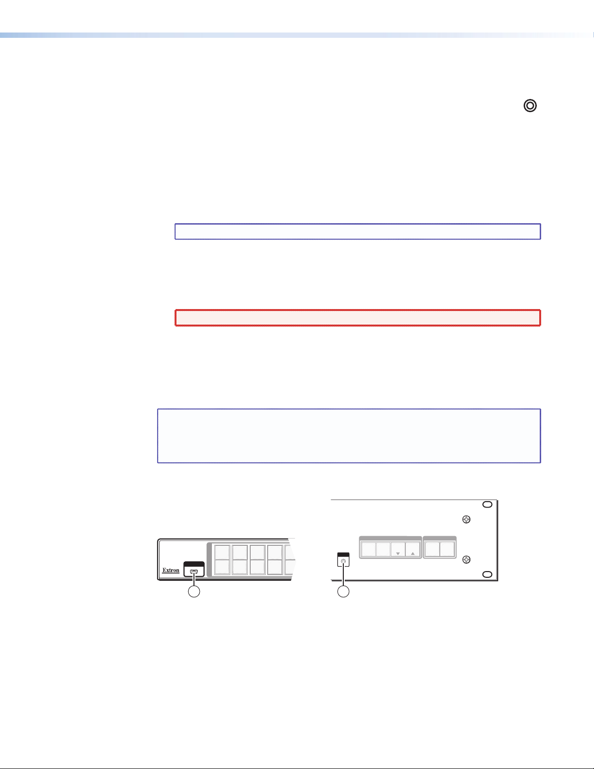
Reset Button
All other MTPX Plus models
l Reset button — The Reset button initiates two levels of reset to the matrix
switcher. For two different reset levels, press and hold the button while the
switcher is running or while you power up the switcher.
See “Rear Panel Operations” in the “Operation” section for details.
• Rear panel (mode 5) system reset — Press and hold the Reset button until the Reset
LED blinks three times (approximately 9 seconds), then release the button and push it
again. This reset clears all ties and presets and resets all audio gains to 0 dB.
• Hard reset — Press and hold the Reset button while powering up the switcher to
perform all of the mode 5 reset functions and restore the switcher to the default factory
conditions.
NOTE: Hard reset does not clear the current configuration.
Power Connection
m AC power connector — Plug a standard IEC power cord into this connector to
connect the switcher to a 100 VAC to 240 VAC, 50 or 60 Hz power source.
WARNING: The power connector is wired double pole with neutral fusing.
Front Panel Configuration Port
This front panel configuration port serves a similar communications function as the rear
panel Remote port, but it is easier to access than the rear port after the matrix switcher has
been installed and cabled.
RESET
NOTES: • The Configuration port is independent of the rear panel Remote port and is
not affected by changes to the protocol of the rear panel port.
• A front panel Configuration port connection and a rear panel Remote port
connection can both be active at the same time.
Figure 14 shows the Configuration port for the various MTPX Plus models.
MTPX Plus 128
CONFIG
I
N
P
U
1
T
O
U
T
P
U
T
223
1
4
5
3
4
5
CONFIG
1514
ENTERPRESET
CONTROL
ESC
VIEW
MTPX PLUS SERIES SWITCHER
VIDEO
I/O
AUDIO
Figure 14. Front Panel Configuration Port
n Configuration port (MTPX Plus 128 only) — A mini USB B port.
o Configuration port — A 2.5 mm mini stereo jack. The optional 9-pin D to 2.5 mm
mini jack TRS RS-232 cable, part number 70-335-01 (see figure 15, on the next page),
can be used for this connection.
MTPX Plus Series • Installation 20
Page 27
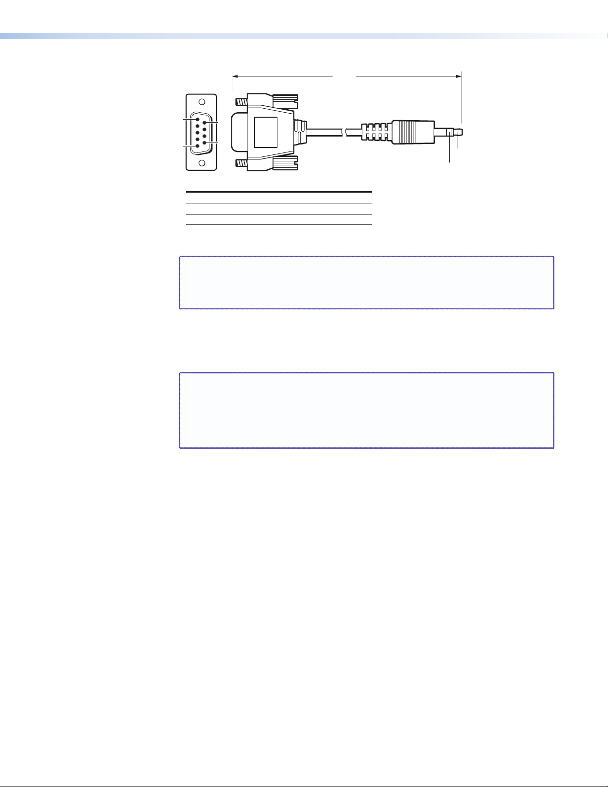
6 feet
(1.8 m)
1
5
9-pin D Connection TRS Plug
Pin 2 Computer's RX line Tip
Pin 3 Computer's TX line Ring
Pin 5 Computer's signal ground Sleeve
6
9
Part #70-335-01
Tip
Ring
Sleeve (Gnd)
Figure 15. Optional 9-pin TRS RS-232 cable
NOTE: The stereo jack Configuration port (item o) protocol can be changed
under SIS command control only (see the Set serial port parameters
SIS Command, in the “Programming Guide” section to configure all ports
under SIS control).
This port is RS-232 only, with its default protocols as follows:
• 9600 baud • no parity • 8 data bits
• 1 stop bit • no flow control
NOTE: The maximum distances from the matrix switcher to the controlling device
can vary up to 200 feet (61 m). Factors such as cable gauge, baud rates,
environment, and output levels (from the switcher and the controlling
device) all affect transmission distance. Distances of about 50 feet (15 m)
are typically not a problem. In some cases the matrix switcher may be
capable of serial communications via RS-232 up to 250 feet (76 m) away.
MTPX Plus Series • Installation 21
Page 28
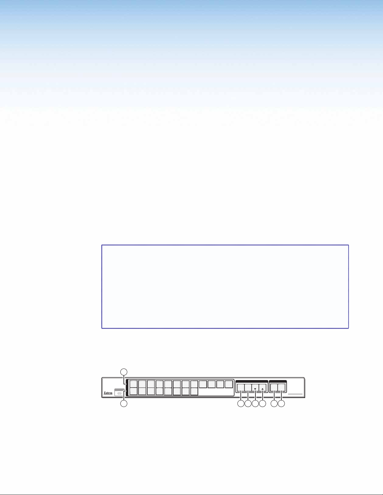
Operation
This section describes the front panel operation of the MTPX Plus Matrix Switcher, including:
• Front Panel Controls and Indicators
• Front Panel Operations
• Rear Panel Operations
• Optimizing the Audio
• Video Adjustments
• Troubleshooting
• Configuration Worksheets
Front Panel Controls and Indicators
The front panel controls (see figure 16 through figure 18) are grouped into two sets. The
input and output buttons, a and b, are grouped on the left side of the control panel. The
control buttons and video/audio (I/O) selection buttons, c through h, are grouped on the
right side of the panel.
NOTES: • While the number of inputs and outputs varies, depending on the size of the
matrix, there are only three front panel arrangements:
• 12 input buttons by 8 output buttons (see figure 16)
• 16 input buttons by 16 output buttons (see figure 17)
• 32 input buttons by 32 output buttons (see figure 18)
• On smaller matrix switchers, the larger-numbered buttons are not used for
input and output selection, although they are used to select and indicate
preset numbers, indicate the input audio level, and indicate the output audio
volume.
The illuminated pushbuttons can be labeled with text, graphics, or both. The buttons
can be set to provide amber background illumination all the time, or the background
illumination can be turned off (see “Background Illumination”, on page 61). The buttons
blink or are lit at full intensity (depending on the operation) when selected.
1
I
N
P
U
1
223
4
CONFIG
5
667
T
O
U
T
1
3
4
P
U
T
5
8
7
8
11
12
10
9
2 3 4
ENTER PRESET
CONTROL
VIEW
ESC
5 6 7 8
I/O
AUDIO
VIDEO
MTPX PLUS SERIES
MTP MATRIX SWITCHER
Figure 16. Front Panel, MTPX Plus 128
MTPX Plus Series • Operation 22
Page 29
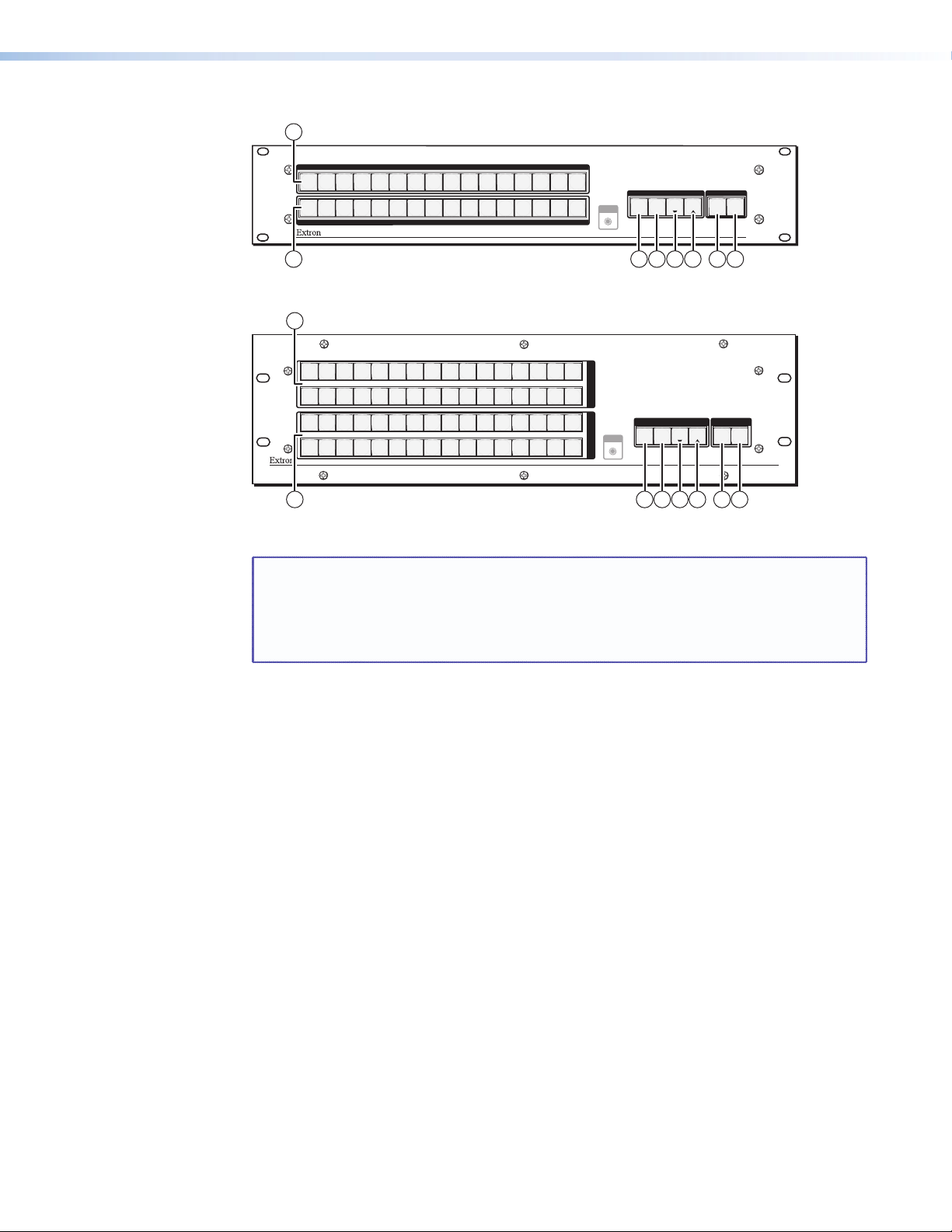
1
INPUTS
2
1
1
4
3
2
4
3
7
6
5
7
6
5
8
8
OUTPUTS
10
9
9
10
11
11
12
12
13
13
14
14
15
15
16
16
2 3 4
Figure 17. Front Panel, MTPX Plus 816, 168, 1616
1
CONFIG
ENTER PRESET
CONTROL
ESC
VIEW
5 6 7 8
I/O
AUDIO
VIDEO
MTPX PLUS SERIES
MTP MATRIX SWITCHER
I
N
P
U
T
S
O
U
T
P
CONFIG
U
T
S
CONTROL I/O
ENTER PRESET
VIEW
ESC
VIDEO AUDIO
MTPX PLUS SERIES
MTP MATRIX SWITCHER
5 6 7 8
17
17
2
1
1
18
18
4
3
20
19
2
4
3
20
19
21
21
5
5
6
22 23
6 7
22 23
7 8
24
24
10
9
25
9
8
25
26
10
26
12
11
27 28
11 12
27 28
13 14 15 16
29 30 31 32
13 14 15 16
29 30 31 32
2 3 4
Figure 18. Front Panel, MTPX Plus 1632, 3216, 3232
NOTES: • Input and output buttons cannot select an input number or output number
that is higher than your matrix size supports. Buttons numbered higher than
your matrix size do have other functions as described in the following pages.
• See “Front Panel Operations” for detailed descriptions of the following
operations.
a Input buttons — See page 25.
b Output buttons — See page 25.
c Enter button — See page 26.
d Preset button — See page 27.
e View button — See page 27.
f Esc button — See page 27.
g Video button — See page 28.
h Audio button — See page 28.
MTPX Plus Series • Operation 23
Page 30
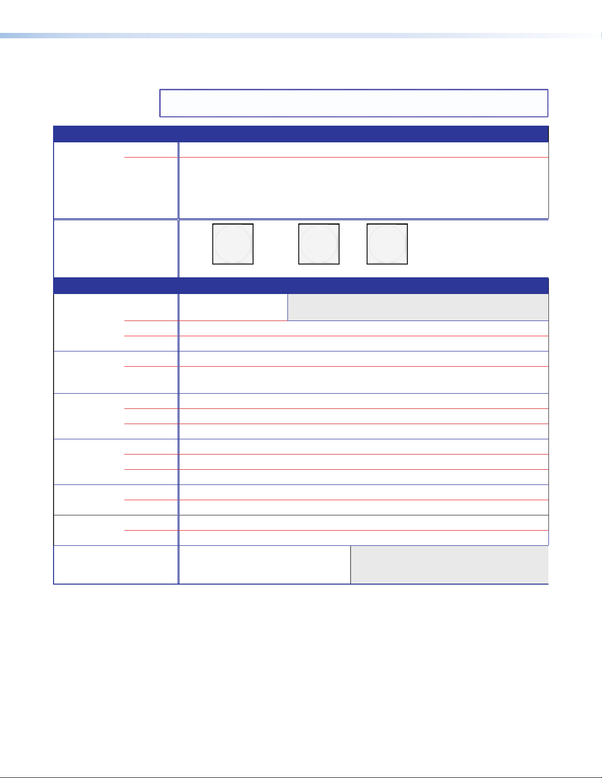
Input and Output Buttons
Primary functions
Action Select input or output for tie being created.
Indication Blink: potential tie/untie.
NOTE: See “Front Panel Operations” for detailed descriptions of the following
operations.
Lit: current tie
Amber: video and audio tie
Green: video only tie
Red: audio only tie
1 2 3
Secondary functions
I/O grouping Action 1 Input 1 and Output 1:
Select I/O Group mode.
Action 2 Assign an input or output to the selected group.
Indication Lit: Input or output is assigned to the selected group.
Presets Action Select a preset in Preset mode.
Indication Lit: A preset has already been saved to this location.
Blink: Preset location is selected to be saved.
Input audio
level
Output audio
volume
Audio or
RS-232 mutes
Input
configuration
Background
illumination
Action Input buttons: Select the input for audio gain or attenuation adjustment.
Indication Input buttons lit: Input audio selected for adjustment.
Indication Output buttons lit or blinking: Indicate the input gain or attenuation level.
Action Output buttons: Select the output for audio volume adjustment.
Indication Output buttons lit: Output audio is selected for adjustment.
Indication Input buttons lit or blinking: Indicated the output volume level.
Action Output buttons: Press and hold to mute or unmute the audio or RS-232 output.
Indication Output buttons blinking: Output audio or RS-232 is muted.
Action Input buttons: Toggle between audio or RS-232 as the pins 3 and 6 input.
Indication Input buttons lit: RS-232 Unlit: audio
Action Input 1 and Input 2 buttons:
Toggle between background
illumination or buttons unlit.
through {highest numbered input or
output button}
MTPX Plus Series • Operation 24
Page 31

a Input buttons — The input buttons have one primary function (❏) and six secondary
functions (•):
❏ Select and identify an input.
• (Input 1 only) With the Output 1 button, select I/O Group mode.
• Assign an input to the selected group in I/O Group mode and indicate its
assignment.
• Select a preset.
• Display the output volume level.
• Select and identify the audio/RS-232 wire pair as audio (unlit) or RS-232 (lit) in Serial
Port and Audio/RS-232 Input Configuration mode.
• (Input 1 and Input 2 only) Toggle background illumination of the buttons on and
off.
b Output buttons — The output buttons have one primary function (❏) and five
secondary functions (•):
❏ Select and identify an output.
• (Output 1 only) With the Input 1 button, select I/O Group mode.
• Assign an output to the selected group in I/O Group mode and indicate its
assignment.
• Select a preset.
• Mute the audio or RS-232 output..
• Display the audio level of the selected input.
MTPX Plus Series • Operation 25
Page 32
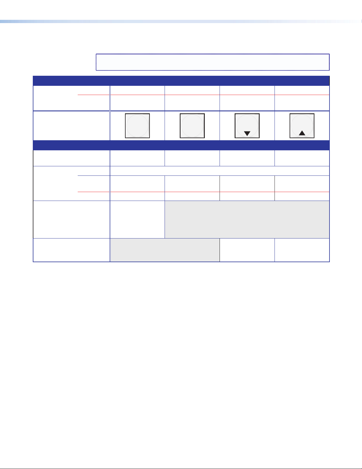
Control Buttons and LEDs
NOTE: See “Front Panel Operations” for detailed descriptions of the following
Primary functions
Action Save changes Select Preset mode Select View mode Cancel/Escape
Indication Blink: Save needed Blink: Save preset
operations.
Lit: Recall preset
View mode
selected
Flashes once
ENTER PRESET
VIEW
ESC
Secondary functions
I/O grouping Action/
indication
Port and input
configuration
Action 1 Select Configuration mode.
Action 2 Select 9600 baud Select 19200 baud Select 38400 baud Select 115200
Select and indicate
group 1
Select and indicate
group 2
Select and indicate
group 3
Select and indicate
group 4
baud
Indication Blink: 9600 baud Blink: 19200 baud Blink: 38400 baud Blink: 115200 baud
Front panel
locks
Action With Video and
Audio, select Lock
mode 2 or toggle
between mode 0
and mode 0.
Audio Action In Audio mode,
decrease input level
or output volume.
In Audio mode,
increase input level
or output volume.
c Enter button — The Enter button has two primary functions (❏) and four secondary
functions (•):
❏ Saves configuration or preset changes that you make on the front panel. To create a
simple configuration:
Specify video, audio, or both (see I/O buttons [item g] and [item h]).
Press the desired input button (item a).
Press the desired output button or buttons (item b).
Press the Enter button.
❏ Indicates that a potential tie has been created but not saved.
• In the I/O Group mode, selects group 1 and indicates the selection.
• With the Preset, View, and Esc buttons, selects Serial Port and Audio/RS-232 Input
Configuration mode.
• Selects 9600 baud for the rear panel Remote port in Serial Port and Audio/RS-232
Input Configuration mode and indicates the selection.
• With the Video and Audio buttons, selects front panel security Lock mode 2 or
toggles between mode 0 (unlocked) and mode 2.
MTPX Plus Series • Operation 26
Page 33

d Preset button — The Preset button has two primary functions (❏) and three
secondary functions (•):
❏ Activates Save Preset mode to save a configuration as a preset and Recall Preset
mode to activate a previously-defined preset.
❏ Blinks when Save Preset mode is active and lights steadily when Recall Preset mode
is active.
• In the I/O Group mode, selects group 2 and indicates the selection.
• With the Enter, View, and Esc buttons, selects Serial Port and Audio/RS-232 Input
Configuration mode.
• Selects 19200 baud for the rear panel Remote port in Serial Port and Audio/RS-232
Input Configuration mode and indicates the selection.
e View (<) button — The View (<) button has one primary function (❏) and five
secondary functions (•):
❏ Select and indicate View-only mode, which displays the current configuration.
NOTE: View-only mode also provides a way to mute and unmute the audio or
RS-232 outputs.
• In the I/O Group mode, selects group 3 and indicates the selection.
• Decreases the audio level of the selected input.
• Decreases the volume of the selected output.
• With the Enter, Preset, and Esc buttons, selects Serial Port and Audio/RS-232 Input
Configuration mode.
• Selects 38400 baud for the rear panel Remote port in Serial Port and Audio/RS-232
Input Configuration mode, and indicates the selection.
f Esc (>) button — The Esc (>) button has two primary functions (❏) and five secondary
functions (•):
❏ Cancels operations or selections in progress and resets the front panel button
indicators.
NOTE: The Esc (>) button does not reset the current configuration, the Video
button and Audio selection button, any presets, or any audio gain or
attenuation or volume settings.
Flashes once to indicate that the escape function has been activated.
❏
• In the I/O Group mode, selects group 4 and indicates the selection.
• Increases the audio level of the selected input.
• Increases the volume of the selected output.
• With the Enter, Preset, and View buttons, selects Serial Port and Audio/RS-232 Input
Configuration mode.
• Selects 115200 baud for the rear panel Remote port in Serial Port and Audio/RS-232
Input Configuration mode and indicates the selection.
MTPX Plus Series • Operation 27
Page 34
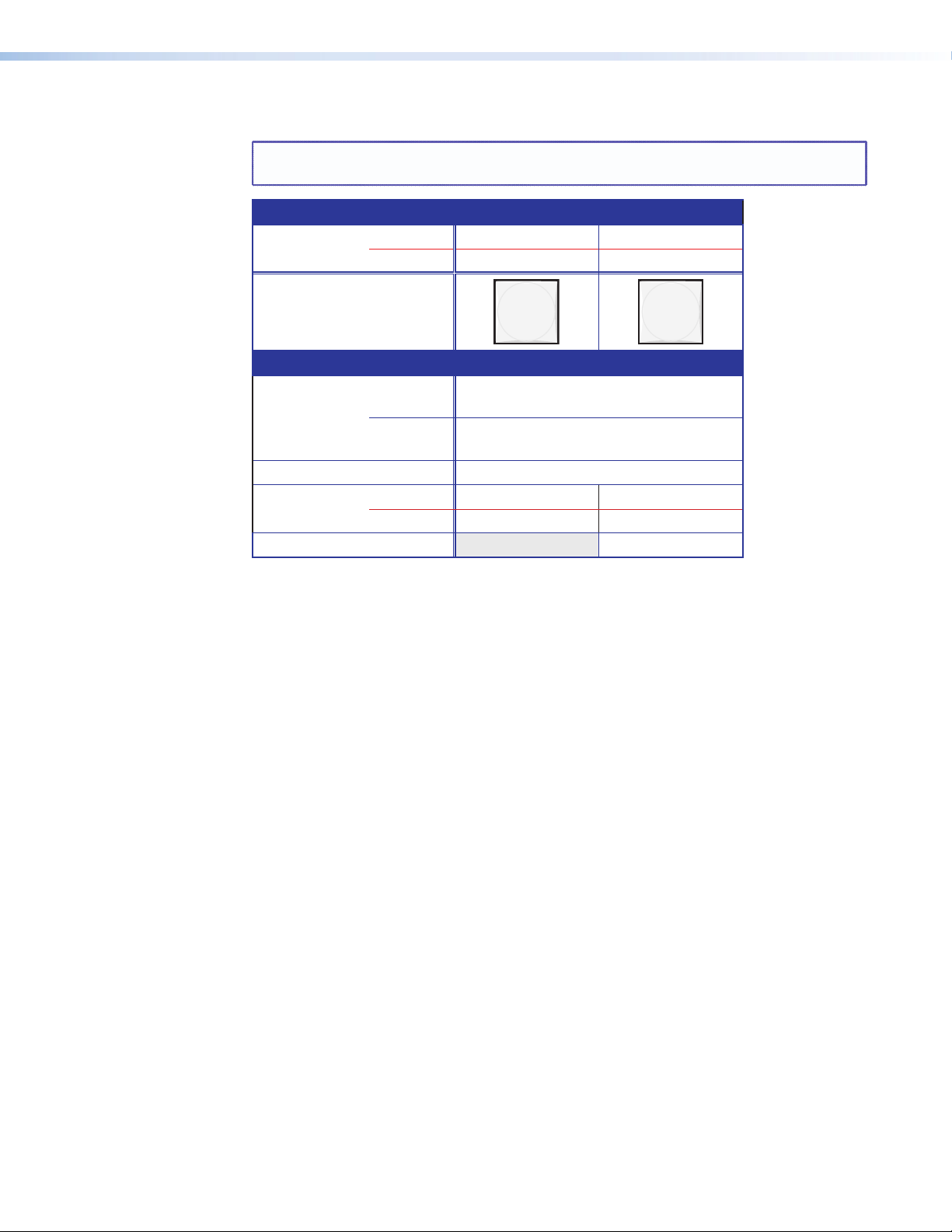
I/O Controls
NOTE: See “Front Panel Operations” for detailed descriptions of the following
operations.
Primary functions
Action Select video Select audio
Indication Green: selected Red: selected
VIDEO AUDIO
Secondary functions
Front panel
locks
Resets Action 1: Perform a system reset.
Port
Configuration
Audio Action Select Audio mode.
Action 1 With Enter, select Lock mode 2 or toggle
between mode 0 and mode 2.
Action 2 Select Lock mode 1 or toggle between
mode 2 and mode 1.
Action Select RS-232. Select RS-422
Indication Blink: selected Blink: selected
g Video button — The Video button has one primary function (❏) and four secondary
functions (•):
❏ Selects and deselects video for a configuration that is being created or viewed and
lights green to indicate that video is available for configuring or for viewing.
• With the Enter button and Audio button, selects between front panel locks
(Lock mode 2 and Lock mode 0).
• With the Audio button, selects between front panel locks (Lock mode 2 and
Lock mode 1).
• With the Audio button, commands the front panel system reset.
• Switchers other than MTPX Plus 128 — Selects the RS-232 protocol for the rear
panel Remote port in Serial Port and Audio/RS-232 Input Configuration mode and
indicates the selection.
h Audio button — The Audio button has one primary function (❏) and five secondary
functions (•):
❏ Selects and deselects audio for a configuration that is being created or viewed and
lights to indicate that audio is available for configuration or viewing.
• Selects the Audio mode, in which you can adjust the input audio level and the
output audio volume.
• With the Enter button and Video button, selects between front panel locks
(Lock mode 2 and Lock mode 0)
• With the Video button, selects between front panel locks (Lock mode 2 and
Lock mode 1).
• With the Video button, commands the front panel system reset.
• Switchers other than MTPX Plus 128 — Selects the RS-422 protocol for the rear
panel Remote port in Serial Port and Audio/RS-232 Input Configuration mode and
indicates the selection.
MTPX Plus Series • Operation 28
Page 35
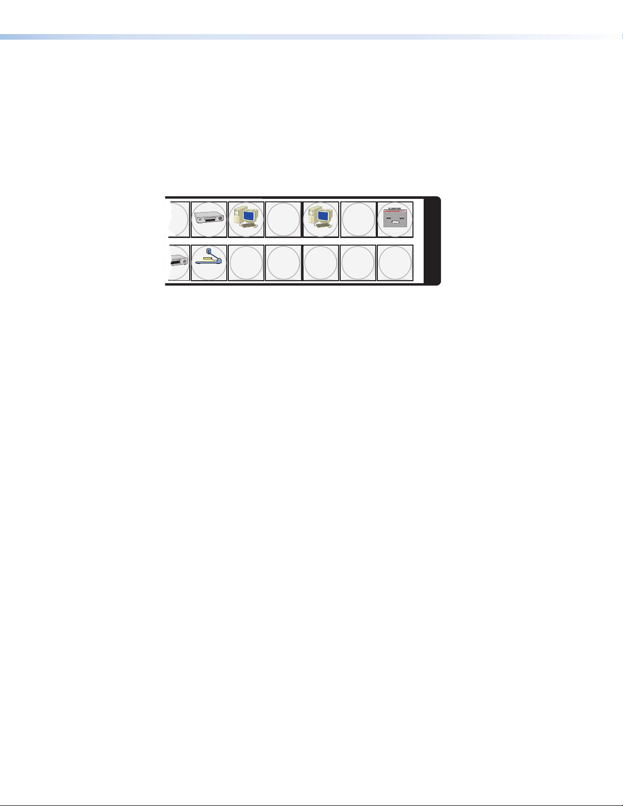
Button Icons
The numbered translucent covers on the input and output pushbuttons can be removed and
replaced to insert labels behind the covers.
Input and output labels can be created easily with the Extron Button-Label Generator
software, which is shipped with every Extron matrix switcher. Each input and output can be
labeled with names, alphanumeric characters, or color bitmaps for easy and intuitive input
and output selection (see figure 19). See the “Matrix Software” section for details on
using the labeling software and the “Reference Information” section for blank labels and
a procedure for removing and replacing the translucent covers.
Figure 19. Sample Button Icons
Front Panel Operations
The following sections detail the power-up process and then provide sample procedures for
the following actions:
• Creating ties, sets of ties, and configurations
• Changing a configuration
• Viewing ties, sets of ties, and configurations
• Creating I/O groups
• Saving a preset
• Recalling a preset
• Muting and unmuting outputs
• Viewing and Adjusting the Input Audio Level
• Viewing and Adjusting the Local Output Volume
• Locking and unlocking the front panel
• Performing front panel resets
• Toggling background illumination on and off
• Defining the Audio/RS-232 Wire Pair
• Reading and setting the Remote port settings
DVD
VCR
Document
Camera
Computer Computer
13 15
2928 30 31 32
VTG 200
I
N
P
U
T
S
MTPX Plus Series • Operation 29
Page 36

Definitions
The following Extron matrix switcher terms are used throughout this manual:
Tie — An input-to-output connection
Set of ties — An input tied to two or more outputs.
NOTE: An output can never be tied to more than one input.
Configuration — One or more ties or one or more sets of ties
Current configuration — The configuration that is currently active in the switcher (also
called configuration 0)
Global memory preset — A configuration that has been stored. Up to 32 global memory
presets can be stored in memory. Preset locations are assigned to the input buttons and
(where necessary) output buttons. When a preset is retrieved from memory, it becomes the
current configuration.
All models have 32 presets. On the MTPX 128 Plus, which has fewer than 32 input and
output buttons, preset numbers that are too high to be available from the front panel are
still accessible under remote or Ethernet control.
Room — A subset of outputs that are logically related to each other, as determined by the
operator. The switchers support up to 10 rooms, each of which can consist of from 1 to 16
outputs.
Room memory preset — A configuration consisting of outputs in a single room that
has been stored. When a room preset is retrieved from memory, it becomes the current
configuration.
Power
Apply power by connecting the power cord between the switcher and an AC source. The
switcher performs a self-test that flashes the front panel button indicators red, green, and
amber and then turns them off. An error-free power-up self-test sequence leaves all input,
output, and control buttons either unlit or showing background illumination and the Video
button and the Audio button lit.
The current configuration and all presets are saved in non-volatile memory. When power is
applied, the most recent configuration is retrieved. The previous presets remain intact.
If an error occurs during the self-test, the switcher locks up and does not operate. If your
switcher locks up on power-up, call the Extron S3 Sales and Technical Support Hotline. See
the end of this guide for the phone number in your region of the world.
Front Panel Security Lockouts
In the procedural descriptions that follow, it is assumed that the switcher is in Lock mode 0
(fully unlocked). The following two Lock modes are also available:
• Lock mode 1 — All changes are locked from the front panel (except for setting Lock
mode 2). Some functions can be viewed.
• Lock mode 2 — Advanced features are locked and can be viewed only. Basic functions
are unlocked.
NOTE: The switcher is shipped from the factory in Lock mode 2. See “Setting the
Front Panel Locks (Executive Modes)” on page 59 for a detailed list of basic
and advanced functions and the procedure to set the various front panel locks.
MTPX Plus Series • Operation 30
Page 37

Creating a Configuration
The current configuration can be changed using the front panel buttons. Change the current
configuration as follows:
1. Press the Esc button to clear any input button indicators, output button indicators, or
control button indicators that may be lit.
2. Select video, audio, or both for configuration by pressing the Video button and Audio
button as necessary.
3. Select the desired input and output(s) by pressing the input and output buttons.
• Input buttons and output buttons light or blink:
• Amber to indicate video and audio ties
• Green to indicate video only ties
• Red to indicate audio only ties
• To indicate potential ties, output buttons blink the appropriate color when an input
is selected.
• To indicate current ties, output buttons light steadily the appropriate color when an
input is selected.
• To clear unwanted outputs, press and release the associated lit output buttons. To
indicate potential unties, output buttons blink the appropriate color when an output
is deselected but not untied from the input.
4. Press and release the Enter button to accept the tie or to break an existing tie.
5. Repeat steps 1 through 4 to create or clear additional ties until the desired configuration
is complete.
NOTES: • Only one video input and one audio input can be tied to an output.
• If a tie is made between an input and an output, and the selected output
was previously tied to another input, the older tie is broken in favor of
the newer tie.
• If an input with no tie is selected, only the button for the selected input
lights.
• When the Video button and the Audio button are lit, if an input with an
audio tie but no video tie is selected, the button for the input and the
button for the output light the appropriate color (amber, green, or red).
• As each input and output is selected, the associated output button blinks
the appropriate color to indicate a tentative tie. Buttons for outputs that
were already tied to the input light the appropriate color steadily. Outputs
that are already tied can be left on, along with new blinking selections, or
toggled off by pressing the associated output button.
• If you press the input button for an input that is I/O grouped (see “I/O
grouping“, on page 39) and then try to select an output in a different
group, you cannot select the associated output button. The associated
input button remains lit.
MTPX Plus Series • Operation 31
Page 38

Example 1: Create a set of video and audio ties
C O N T R O L
PRESET
ENTER
ESCVIEW
Press the Esc button to clear all selections.
The button flashes once.
I / O
VIDEO AUDIO
Press the Video button to toggle on and off.
The button lights green when selected.
Press the Audio button to toggle on and off.
The button lights red when selected.
C O N T R O L
PRESET
ENTER
ESCVIEW
1 2 3 4 5 6 7 8 15 16
17 18 19 20 21 22 23 24 31 32
O
U
T
P
U
T
S
Press the buttons.
The buttons blink amber to indicate that the selected video and audio inputs
will be tied to these outputs.
The Enter button blinks
green to indicate the need to
confirm the change.
ENTER
All input buttons and output buttons
return to unlit or background illumination.
Press the Enter button to
confirm the configuration
change.
The Enter button returns to
unlit or background
illumination.
1. Clear all selections: Press and release the Esc button.
2. Select video and audio for the tie: If necessary, press and release the the Video
button and the Audio button to light both.
3. Select an input: Press and release the input 5 button.
Press the button.
The button lights amber.
1 2 3 4 5 6 7 8 15 16
17 18 19 20 21 22 23 24 31 32
I
N
P
U
T
S
4. Select the outputs: Press and release the output 3, output 4, and output 8 buttons.
NOTE: You can cancel the entire set of ties at this point by pressing and releasing
the Esc button. The Esc button flashes once.
5. Confirm the change: Press and release the Enter button.
MTPX Plus Series • Operation 32
Page 39
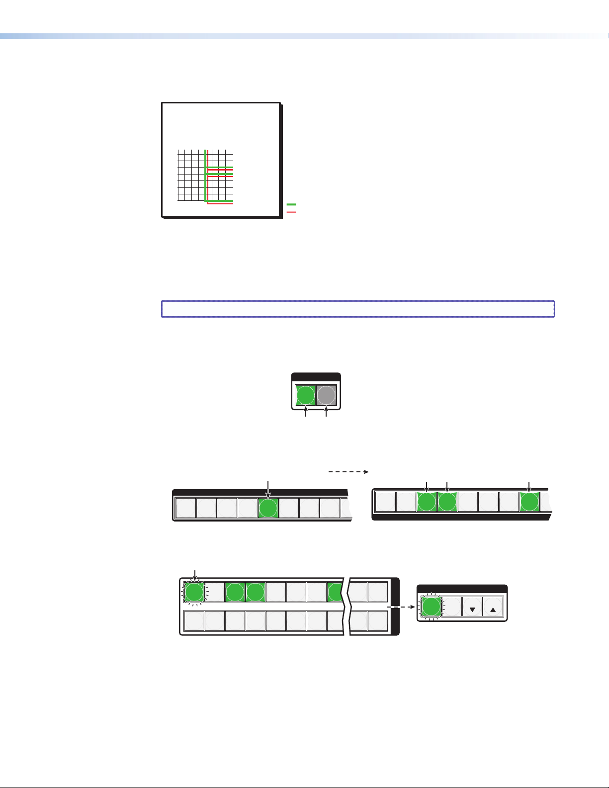
The current configuration (see figure 20) is now:
Input 5 (video/audio) tied
to outputs 3, 4, and 8
Input
Output
3
4
8
5
Video
Audio
I / O
VIDEO AUDIO
Press the Video button to toggle on and off.
The button lights green when selected.
Press the Audio button to toggle on and off.
The button is unlit or background illuminated when deselected.
INPUTS
1
2
3 4
5
6 7 8
9
OUTPUTS
1
2
3 4
5
6
7 8
9
Press the button.
The button lights green to indicate that video
outputs can be tied to or untied from this input.
The Output 3, Output 4, and Output 8 buttons light
green to indicate the video ties created in example 1.
1 2 3 4 5 6 7 8 15 16
17 18 19 20 21 22 23 24 31 32
O
U
T
P
U
T
S
Press the button.
The button blinks green to indicate that only the selected video
input will be tied to this output.
The Enter button blinks
green to indicate the need to
confirm the change.
C O N T R O L
PRESET
ENTER
ESCVIEW
• Input 5 video and audio are tied to output 3, output 4, and output 8
Figure 20. Example 1, Final Configuration
Example 2: Add a video tie to a set of video and audio ties
In the following example, a new video tie is added to the current configuration. The example
shows the front panel indications that result from your actions.
NOTE: This example assumes that you have performed example 1.
1. Clear all selections: Press and release the Esc button.
2. Select video only for the tie: Press and release the Video button and the Audio
button as necessary to light Video only.
3. Select an input: Press and release the Input 5 button.
4. Select the output: Press and release the Output 1 button.
MTPX Plus Series • Operation 33
Page 40

5. Confirm the change: Press and release the Enter button.
ENTER
All input buttons and output buttons
return to unlit or background illumination.
Press the Enter button to
confirm the configuration
change.
The Enter button returns to
unlit or background
illumination.
Input 5 video tied
to outputs 1, 3, 4, and 8
Input 5 audio tied
to outputs 3, 4, and 8
Input
Output
1
3
4
8
5
Video
Audio
I / O
VIDEO AUDIO
Press the Video button to toggle on and off.
The button is unlit or background illuminated
when deselected.
Press the Audio button to toggle on and off.
The button lights red when selected.
The current configuration (see figure 21) is now:
• Video — Input 5 video is tied to output 1, output 3, output 4, and output 8.
• Audio — Input 5 audio is tied to output 3, output 4, and output 8.
Figure 21. Example 2, Final Configuration
Example 3: Remove a tie from a set of ties
In the following example, an existing tie is removed from the current configuration. The
example shows the front panel indications that result from your actions.
NOTE: This example assumes that you have performed example 1 and example 2.
1. Clear all selections: Press and release the Esc button.
2. Select audio only for the tie: Press and release the Video button and the Audio
button as necessary to light Audio only.
MTPX Plus Series • Operation 34
Page 41
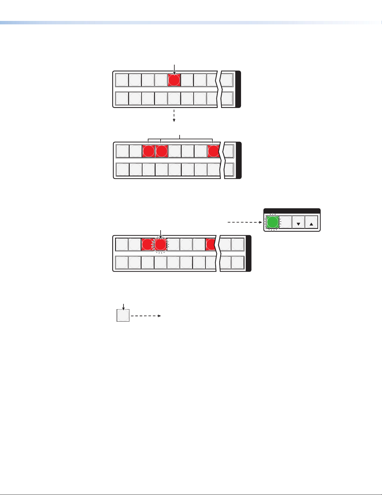
3. Select an input: Press and release the input 5 button.
1 2 3 4 5 6 7 8 16
17 18 19 20 21 22 23 24 32
I
N
P
U
T
S
1 2 3 4 5 6 7 8 16
17 18 19 20 21 22 23 24 32
O
U
T
P
U
T
S
The Output 1 button does not light to indicate the tie
created in example 2 because that tie is video only.
The Output 3, Output 4, and Output 8 buttons light
red to indicate the audio ties created in example 1.
Press the button.
The button lights red.
1 2 3 4 5 6 7 8 15 16
17 18 19 20 21 22 23 24 31 32
O
U
T
P
U
T
S
C O N T R O L
PRESET
ENTER
ESCVIEW
Press the button.
The button blinks red to indicate the pending change:
audio input will be untied.
The Enter button blinks
green to indicate the need to
confirm the change.
ENTER
All input buttons and output buttons
return to unlit or background illumination.
Press the Enter button to
confirm the configuration
change.
The Enter button returns to
unlit or background
illumination.
4. Select the output: Press and release the output 4 button.
5. Confirm the change: Press and release the Enter button.
MTPX Plus Series • Operation 35
Page 42
The current configuration (see figure 22) is now:
Input 5 video tied
to outputs 1, 3, 4, and 8
Input 5 audio tied
to outputs 3 and 8
Input
Output
1
3
4
8
5
Video
Audio
• Video — Input 5 video is tied to output 1, output 3, output 4, and output 8.
• Audio — Input 5 audio is tied to output 3 and output 8.
Figure 22. Example 3, Final Configuration
Viewing the Configuration
The current configuration can be viewed using the front panel buttons. The View-only mode
prevents inadvertent changes to the current configuration. View-only mode also provides
a way to mute audio or RS-232 outputs (see “Muting and Unmuting Audio/RS-232
Outputs” on page 46).
View the current configuration as follows:
1. Press the Esc button to clear any input button indications, output button indications, or
control button indications that may be on.
2. Press and release the View button. All of the buttons light for outputs that are not tied
as follows:
• Amber: No tied video or audio input
• Green: No tied video input
• Red: No tied audio input
If you press an output button for which there are no ties, the output buttons light for all
outputs without ties.
3. Select video, audio, or both to view by pressing the Video button, Audio button, or
both.
4. Select the desired input or output(s) whose ties you wish to view by pressing the input
and output buttons.
NOTES: • To see all ties of the current configuration, press and release each input
and output button, one at a time, with the Video button and the Audio
button lit.
• When you view video and audio ties, the Video button is lit green and
the Audio button is lit red. After you select an input or output, the output
buttons light different colors to show where video and audio ties are not
the same (audio is broken away). Amber indicates video and audio, green
indicates video only, and red indicates audio only.
• After 30 seconds of front panel inactivity, View-only mode automatically
deselects.
MTPX Plus Series • Operation 36
Page 43
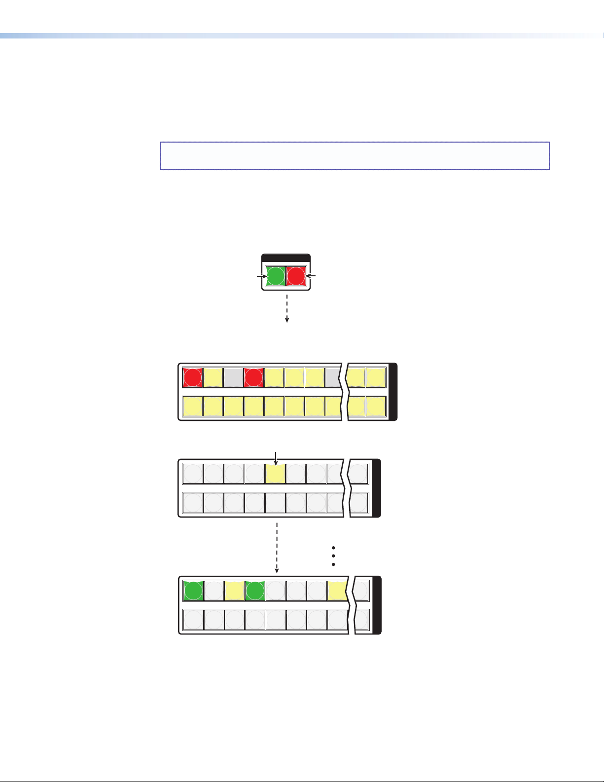
Example 4: Viewing video and audio (RS-232), audio (RS-232) only,
1 2 3 4 5 6 7 8 15 16
17 18 19 20 21 22 23 24 31 32
O
U
T
P
U
T
S
I / O
VIDEO AUDIO
Until you select an input, the buttons for all untied
outputs light amber if no inputs are tied, green if no
video inputs are tied (only audio is tied), or red if no
audio or RS-232 inputs are tied (only video is tied).
Press the Audio button
to toggle on and off.
The button lights red
when selected.
Press the Video button
to toggle on and off.
The button lights
green when selected.
1 2 3 4 5 6 7 8 16
17 18 19 20 21 22 23 24 32
I
N
P
U
T
S
1 2 3 4 5 6 7 8 16
17 18 19 20 21 22 23 24 32
U
O
T
P
U
T
S
The output buttons for outputs that are not tied to Input 5 are
either unlit or background illuminated.
The output buttons for outputs that are tied to Input 5
light or blink the appropriate color:
Lit amber for audio and video ties (audio follow)
Lit green for video ties (audio breakaway)
Red for audio/RS-232 ties (audio/RS-232 breakaway)
Press the button. It lights amber.
and video only ties
In the following example, we view the video and audio (or RS-232), audio- (or RS-232) only,
and video-only ties in the current configuration. The steps show the front panel indications
that result from your action.
NOTE: This example assumes that you have performed example 1, example 2, and
example 3.
1. Clear all selections: Press and release the Esc button.
2. Select View-only mode: Press and release the View button. The View button lights
red.
3. Select video and audio for viewing: Press and release the Video button and the
Audio button as necessary to light both.
4. Select an input: Press and release the input 5 button.
MTPX Plus Series • Operation 37
Page 44

NOTE: You can also view a set of ties by selecting a tied output. Demonstrate this
1 2 3 4 5 6 7 8 15 16
17 18 19 20 21 22 23 24 31 32
O
U
T
P
U
T
S
I / O
VIDEO AUDIO
Press the button.
The button is unlit or
background illuminated
when deselected.
The Audio button
remains lit red to
indicate that only
audio is selected.
The output buttons for outputs that are not tied to Input 5 are
either unlit or background illuminated.
The output buttons for outputs that are tied to Input 5 light
red to indicate audio or RS-232 ties (audio breakaway).
1 2 3 4 5 6 7 8 15 16
17 18 19 20 21 22 23 24 31 32
O
U
T
P
U
T
S
I / O
VIDEO AUDIO
The output buttons for outputs that are not tied to Input 5 are
either unlit or background illuminated.
The output buttons for outputs that are tied to Input 5
light green to indicate video ties (audio breakaway).
Press button.
The button lights
green when selected.
Press the button.
The button is unlit
or background
illuminated when
deselected.
All input buttons and output buttons
return to unlit or background illumination.
VIEW
Press the button.
The View button returns to unlit or background illumination.
as follows:
• Note the number of a lit output button, and then press and release the
output button for an untied (unlit or background illumination) output.
• Observe that all of the untied outputs light.
• Then press the output button that you noted previously
• Observe that the selected output button, the tied input button (input
5), and the output buttons light for all of the outputs that are tied to
the input.
5. Deselect video: Press and release the Video button.
6. Toggle audio off and video on: Press and release the Video button and the Audio
button.
If video ties are established for input 5, the output buttons light green for all video
outputs tied to input 5. If no ties are established for input 5, all output buttons return to
either unlit or to background illumination.
7. Exit View-only mode: Press and release the View button
MTPX Plus Series • Operation 38
Page 45

I/O Grouping
10
26 27
9910 11
26 27
1 2 3 4 5 6 7 8
171718 19 20 21 22 23 24
1 2 3 4 5 6 7 8
18 19 20 21 22 23 24 25
25
USP 405
UNIVERSAL SIGNAL PROCESSOR
ADJUST
MENU
NEXT
FREEZE
12345
PICTURE ADJUSTMENTS
CENTERSIZEBRT/CONT COL/TNT ZOOM DETAIL
INPUTS
RGB
UNIVERSAL
FREEZE
COMPOSITE
S-VIDEO SDI
VCR
DVD
Document Camera
VSC 700
SCAN CONVERTER
SIZE
MIN/MAX
NEXTMENU
FREEZE
RESET
IR
CENTER/PAN/SIZE
Monitor
Projector
VSC 700
Computer #1
Computer #3
3 input, 4 output
RGBHV matrix
5
6
7
8
24 25 26
Input
Output
Group 3
4 input, 2 output
composite video matrix
Camera #1
Camera #4
3 input, 2 output
S-video matrix
Monitor
Monitor
Group 1
Group 2
Group 1 Group 2 Group 3
17 18 19
Input
1
2
20
Output
3
4
21 22 23
Input
Output
Monitor
USP 405
NOTE: All of the equipment in this figure is connected through the appropriate MTP transmitter or receiver.
I/O grouping is a matrix switcher feature that allows you to subdivide the front panel
controls of the matrix into four smaller functional sub-switchers and limit tie creation using
the front panel only. Inputs and outputs can be assigned to one of four groups or not
assigned to any group.
When you are creating ties on the front panel, inputs and outputs that are assigned to a
group can be tied only to other outputs and inputs within the same group. For example,
a front panel operator cannot tie an input that is assigned to group 1 to an output that is
assigned to group 2. Ungrouped inputs and outputs can be switched to outputs and inputs
in any group. Ties between groups (an input in group 1 tied to an output in group 2) can be
created under serial port, USB port, or Ethernet control.
Suggested applications for the I/O grouping feature include:
• Segregating specific video formats to prevent an input in one video format from being
inadvertently applied to an output device that supports another video format (see
figure 23)
• Segregating input and output devices that are in separate rooms
• Segregating input and output devices on which you are distributing audio on the audio/
RS-232 wire pair from those on which you are distributing RS-232 signals.
• Isolating video from being displayed on specific output devices for operational security
reasons.
Figure 23. I/O Grouping of Incompatible Video Formats
The I/O groups can be set up on the front panel or by using Remote port, USB port, or LAN
ports and either the SIS (see the “Programming Guide” section) or the Matrix Switchers
Control Program (see the “Matrix Software” section.
MTPX Plus Series • Operation 39
Page 46
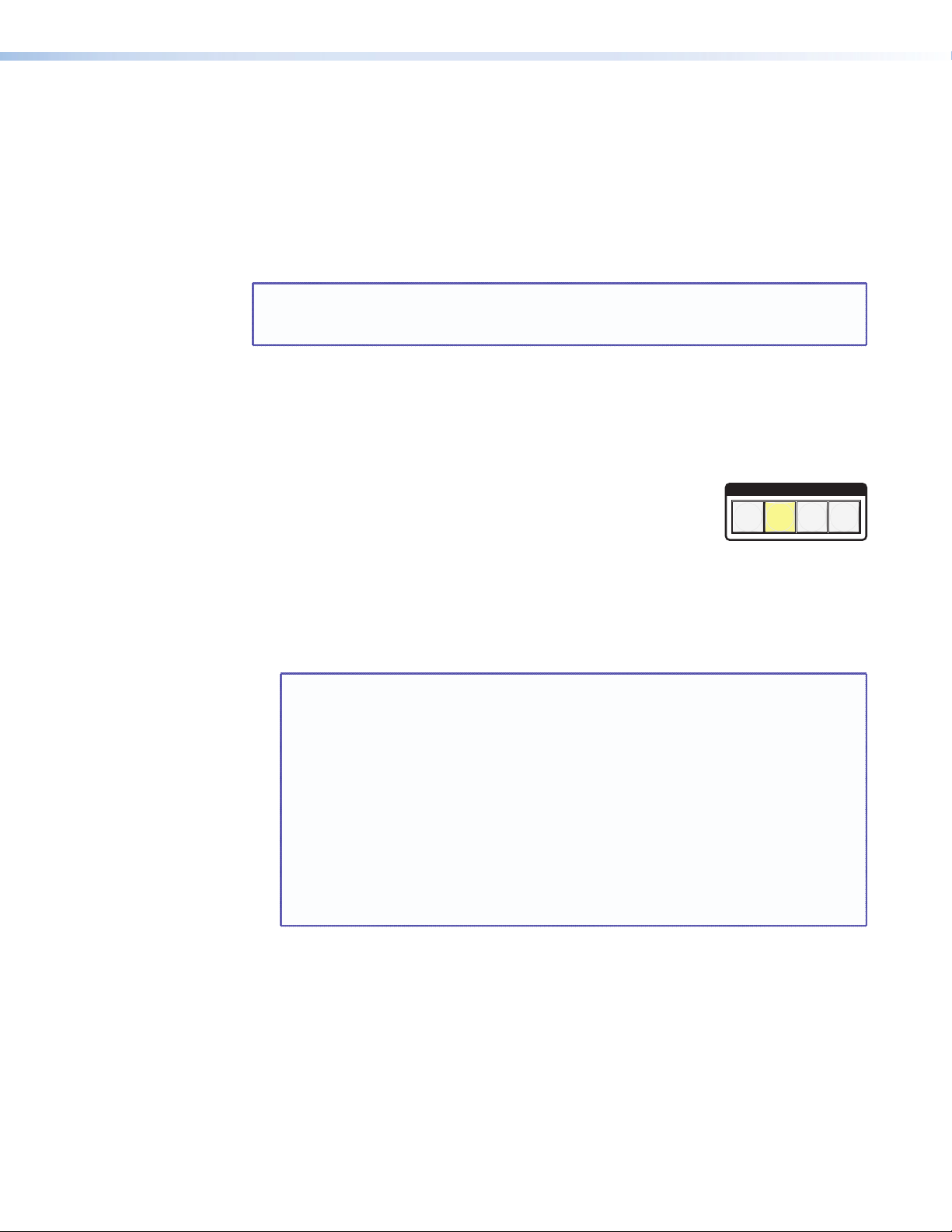
You can break audio away from the video for a given input or output (assign video and
1324
audio to different groups) by isolating only video or only audio using the front panel Video
and Audio buttons after you select I/O Group mode (between steps 2 and 3, below).
Audio breakaway across different groups can be confusing when you are operating the
front panel. Breakaway grouping is not displayed by the Matrix Switchers Control Program,
HTML pages, or SIS commands; and is not recommended (breakaway ties, once created, are
displayed).
Create I/O groups on the front panel as follows:
NOTE: I/O groups are protected when front panel Lock mode 2 is selected. You can
view the groups in Lock mode 2, but you cannot change them from the front
panel (see “Setting the Front Panel Locks (Executive Modes)” on page 59).
1. Press the Esc button to clear any input buttons, output buttons, or control buttons that
may be lit.
2. To enter I/O Group mode, press and hold the Input 1 and Output 1 buttons until the
input and output buttons light to display the ungrouped inputs and outputs.
3. Press and release one of the Control buttons to select a group:
ENTER
C O N T R O L
PRESET
ESCVIEW
• Press the Enter button to select group 1.
• Press the Preset button to select group 2.
• Press the View button to select group 3.
Group #
• Press the Esc button to select group 4.
4. Select the desired input or inputs and output or outputs to assign to the group by
pressing the input and output buttons.
5. Press and release the Video and Audio button to exit the I/O Group mode, or allow the
mode to time out after approximately 30 seconds.
NOTES: • Ties between groups (an input in group 1 tied to an output in group 2)
can be created under serial port, USB port, or Ethernet control.
• Ties that were created before I/O groups were created remain valid, even
if they include inputs and outputs in different groups.
• Presets can be created under serial port, USB port, or Ethernet control
that tie inputs and outputs across group boundaries. These presets are
selectable from the front panel.
• An input or output can be assigned to only one group. If you assign an
input or output to a group and that input or output is already assigned
to a different group, the older grouping is discarded in favor of the new
grouping.
• For I/O groups to have any function, at least two groups must be created.
MTPX Plus Series • Operation 40
Page 47
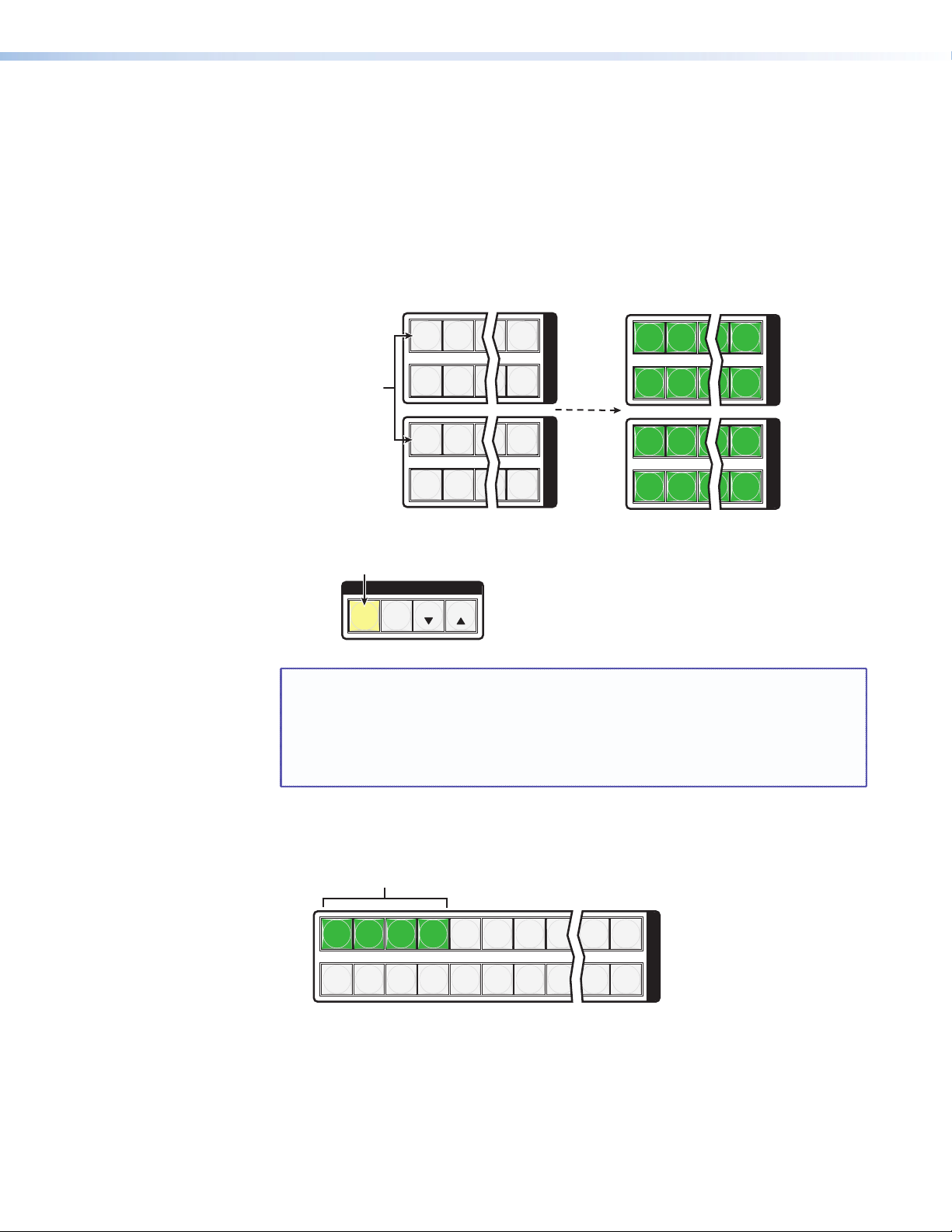
Example 5: Grouping inputs and outputs
1 2 5 16
17 18 11 32
1 2 5 16
17 18 11 32
I
N
P
U
T
S
O
U
T
P
U
T
S
1 2 5 16
17 18 11 32
1 2 5 16
17 18 11 32
I
N
P
U
T
S
O
U
T
P
U
T
S
•
Press and hold
the Input 1 button
and Output 1 button.
Release the Input 1 button
and Output 1 button.
Ungrouped input and
output buttons light.
2 seconds
C O N T R O L
PRESET
ENTER
ESCVIEW
1324
Press the button.
The button lights amber to indicate the selection.
Group #
1 2 3 4 5 6 7 8 15 16
17 18 19 20 21 22 23 24 31 32
I
N
P
U
T
S
Press the buttons.
The selected buttons light green.
In the following example, several switcher inputs and outputs are assigned to groups. The
steps show the front panel indications that result from your action.
1. Clear all selections: Press and release the Esc button.
2. Enter I/O Group mode: Simultaneously press and hold the Input 1 and Output 1
buttons for approximately 2 seconds and then release the buttons.
3. Select group 1: Press and release the Enter button.
4. Assign inputs and outputs to group 1:
NOTE: I/O groups are protected when front panel Lock mode 2 is selected. You
can view the groups in Lock mode 2, but you cannot change them from the
front panel (see “Setting the Front Panel Locks (Executive Modes)” on
page 59).
If front panel Lock mode 2 is selected and you try to perform step 4, the
actions are ignored and the Enter, Video, and Audio buttons flash.
a. Press and release the Input 1 through 4 buttons.
MTPX Plus Series • Operation 41
Page 48

b. Press and release the Output 1 through 4 buttons.
1 2 3 4 5 6 7 8 15 16
17 18 19 20 21 22 23 24 31 32
O
U
T
P
U
T
S
Press the buttons.
The selected buttons light green.
C O N T R O L
PRESET
ENTER
ESCVIEW
1324
Press the button.
The button lights amber to indicate the selection.
Group #
1 2 3 4 5 6 7 8 15 16
17 18 19 20 21 22 23 24 25 32
I
N
P
U
T
S
Press and release the buttons.
The selected buttons light green.
1 2 3 4 5 6 7 8 15 16
17 18 19 20 21 22 23 24 25 32
I
N
P
U
T
S
Press and release the buttons.
The selected buttons light green.
5. Select group 2: Press and release the Preset button.
6. Assign inputs and outputs to group 2:
a. Press and release the Input 5 through 8 buttons.
b. Press and release the Output 5 through 8 buttons.
7. Exit I/O Group mode: Simultaneously press and release the Video button and Audio
button.
NOTE: If you do nothing for approximately 30 seconds, the front panel times out
and the switcher exits I/O Group mode:
• Group 1 consists of inputs 1 through 4 and outputs 1 through 4.
• Group 2 consists of inputs 5 through 8 and outputs 5 through 8.
MTPX Plus Series • Operation 42
Page 49

Using Presets
I
N
P
U
T
S
1
16 x 32, 32 x 16, and 32 x 32 matrix sizes
Input
buttons
Input
buttons
Output
buttons
Input
buttons
Output
buttons
Preset
1
8 x 16, 16 x 8, and 16 x 16 matrix sizes
Preset
1
Preset6Preset
7
Preset
10
Preset15Preset
16
Preset
11
Preset
3
Preset8Preset
9
Preset4Preset
5
Preset13Preset
14
Preset
12
Preset
2
Preset
17
Preset22Preset
23
Preset
26
Preset31Preset
32
Preset
27
Preset
19
Preset24Preset
25
Preset20Preset
21
Preset29Preset
30
Preset
28
Preset
18
Preset5Preset
6
Preset
10
Preset
7
Preset13Preset14Preset
15
Preset
2
Preset8Preset
9
Preset3Preset
4
Preset11Preset
12
Preset
16
Preset
17
Preset21Preset
22
Preset
26
Preset
23
Preset29Preset30Preset
31
Preset
18
Preset24Preset
25
Preset19Preset
20
Preset27Preset
28
Preset
32
2 3 4 5 6 7 8 9 10 11 12 13 14 15 16
17 18 19 20 21 22 23 24 25 26 27 28 29 30 31 32
MTPX Plus 128 (12 x 8 matrix size)
Preset
1
Preset5Preset
6
Preset
10
Preset
7
Preset
2
Preset8Preset
9
Preset3Preset
4
Preset11Preset
12
Preset13Preset
14
Preset18Preset19Preset
20
Preset15Preset16Preset
17
INPUTS
1
2
3 4
5
6
7
8
9
10
11
12
14
15
16
13
1
2
3
4
5
6
7
8
9
10
11
12
14
15
16
13
OUTPUTS
1
9
10
11
12
1
223
3
4
4
5
5
667
7
8
8
I
N
P
U
T
O
U
T
P
U
T
The current configuration (configuration 0) can be saved as a preset in any one of 32 preset
memory addresses. All 32 presets are assigned to the input buttons and (where necessary)
output buttons and are available to be either saved or retrieved from the front panel.
Up to 20 (MTPX Plus 128) or all 32 (all other models) presets can be selected from the front
panel to be either saved or retrieved. When a preset is retrieved from memory, it becomes
the current configuration.
NOTES: • Only the audio and video ties are stored and recalled; audio gain settings are
not saved, and they do not change when a preset is recalled.
• Presets cannot be viewed from the front panel unless they are recalled as
the current configuration. Presets can be viewed using the Extron Matrix
Switchers Control Program (see the “Matrix Software” section).
• The current configuration and all presets are stored in non-volatile memory.
When power is removed and restored, the current configuration is still active
and all presets are retained.
• When a preset is recalled, it replaces the current configuration, which is lost
unless it is also stored as a preset. The recalled preset overwrites all of the
current configuration ties in favor of the preset configuration ties.
• All models have 32 presets; on the MTPX Plus 128, preset numbers that are
too high to be available from the front panel are still accessible under serial
port, USB, or Ethernet control.
• Figure 24 shows the presets associated with the three input and output
button configurations for the MTPX Plus matrix switchers.
Figure 24. Preset Locations
MTPX Plus Series • Operation 43
Page 50

Example 6: Saving a preset
PRESET PRESET
1 2 3 4 15 16
17 18 19 20 31 32
I
N
P
U
T
S
Press and hold the Preset button until it blinks.
2 seconds
All input buttons with assigned
presets light red.
If you then save the configuration
to a lit preset number, the
configuration data at that preset
location will be overwritten.
Preset Assigned
No Preset Assigned
1 2 3 4 5 6 7 8 15 16
17 18 19 20 21 22 23 24 31 32
I
N
P
U
T
S
C O N T R O L
PRESET
ENTER
ESCVIEW
•
•
•
The Enter button blinks to
indicate the need to save
the preset.
The Preset button
continues to blink.
Press the button.
The button blinks to indicate that this
preset number is selected but not saved.
C O N T R O L
PRESET
ENTER
ESCVIEW
1 2 3 4 15 16
17 18 19 20 31 32
I
N
P
U
T
S
The Enter and Preset
buttons return to unlit or
background illumination.
Press the button.
All input buttons return to unlit or background illumination.
In the following an example, the current configuration is saved as a preset. The example
shows the front panel indications that result from your actions.
1. Clear all selections: Press and release the Esc button.
2. Select Save Preset mode: Press and hold the Preset button for approximately
2 seconds until it blinks.
3. Select the preset: Press and release the input button or output button for the desired
preset.
4. Save the Preset: Press and release the Enter button to save the preset. The current
configuration is now stored in the selected memory location.
MTPX Plus Series • Operation 44
Page 51

Example 7: Recalling a preset
1 2 3 15 16
17 18 19 31 32
I
N
P
U
T
S
PRESET
All input buttons with
assigned presets light red.
Preset Assigned
Press and release the
Preset button.
The Preset button lights.
No Preset Assigned
1 2 3 4 15 16
17 18 19 20 31 32
I
N
P
U
T
S
C O N T R O L
PRESET
ENTER
ESC VIEW
Press and release the Input 1 button.
The button blinks red to indicate that this
preset number is selected but not recalled.
The Enter button blinks
to indicate the need to
recall the preset.
1 2 3 4 15 16
17 18 19 20 31 32
I
N
P
U
T
S
C O N T R O L
PRESET
ENTER ESCVIEW
All input buttons return to unlit or background illumination.
The Enter and Preset
buttons return to unlit or
background illumination.
Press the button.
In the following example, a preset is recalled to become the current configuration. The steps
show the front panel indications that result from your action.
1. Clear all selections: Press and release the Esc button.
2. Select Recall Preset mode: Press and release the Preset button.
3. Select the preset: Press and release the input button or output button for the desired
preset.
4. Recall the preset: Press and release the Enter button. The configuration stored in the
selected memory location is now the current configuration and can be viewed in the
View-only mode (see example 4 on page 37).
MTPX Plus Series • Operation 45
Page 52

Muting and Unmuting Audio/RS-232 Outputs
Individual audio or RS-232 outputs can be muted or unmuted as follows:
NOTE: Output mutes are protected when front panel Lock mode 2 is selected. You
can view the status of the output (muted or unmuted) in Lock mode 2 but you
cannot change it from the front panel (see “Setting the Front Panel Locks
(Executive Modes)” on page 59).
1. Press the Esc button to clear any input button indications, output button indications, or
control button indications that may be on.
2. Press and release the View button.
3. To select audio, press the Audio button if necessary, .
4. One at a time, press and hold the button(s) for the desired output(s) for approximately
2 seconds. The output button(s) for the selected output(s) blink to indicate the mute or
return to their previous state to indicate the unmute.
5. Press and release the View button to return to normal switcher operation.
NOTES: • You can mute only audio or RS-232 outputs, not video.
• When you enter View-only mode, the output LEDs turn on for all outputs
without ties.
• If the audio/RS-232 wire pair of the selected input is defined as RS-232
(see “Defining the Audio/RS-232 Wire Pair” on page 62), the serial
output is muted.
• Mutes are saved to non-volatile memory. When power is removed and
restored, the mute settings are retained.
MTPX Plus Series • Operation 46
Page 53

Example 8: Muting and unmuting an audio/RS-232 output
1 2 3 4 5 6 7 8 15 16
17 18 19 20 21 22 23 24 31 32
O
U
T
P
U
T
S
I / O
VIDEO AUDIO
Until you select an input, the buttons for
all outputs with no audio ties light red.
Press the button.
The button lights red
when selected.
Video cannot be
muted. The lit
status of the button
is unimportant.
3
3
The button blinks to indicate that the
audio or RS-232 output is muted.
2 seconds
Press and hold the Output 3 button.
3
3
2 seconds
Press and hold.
The button returns to its previous indication
(either lit red, background illuminated, or
unlit) to indicate that the output is unmuted.
All input buttons and output buttons
return to unlit or background illumination.
VIEW
Press the button.
The View button returns to unlit or background illumination.
In the following example, a switcher output is muted and unmuted. The steps show the
front panel indications that result from your action.
1. Clear all selections: Press and release the Esc button.
2. Select View-only mode: Press and release the View button. The View button lights
red.
3. Select audio (or RS-232) for viewing and muting: If necessary, press and release the
Audio button.
NOTE: This example assumes that you have performed example 1, example 2,
and example 3.
NOTE: Output mutes are protected when front panel Lock mode 2 is selected. You
can view the mutes in Lock mode 2 but you cannot change them from the
front panel (see “Setting the Front Panel Locks (Executive Modes)” on
page 59).
If front panel Lock mode 2 is selected and you try to perform steps 4 and 5,
the actions are ignored.
4. Mute an output: Press and hold the Output 3 button for approximately 2 seconds until
the button begins to blink..
5. Unmute an output: Press and hold the Output 3 button for approximately 2 seconds
until the button returns to its previous state.
6. Exit View-only mode: Press and release the View button.
MTPX Plus Series • Operation 47
Page 54
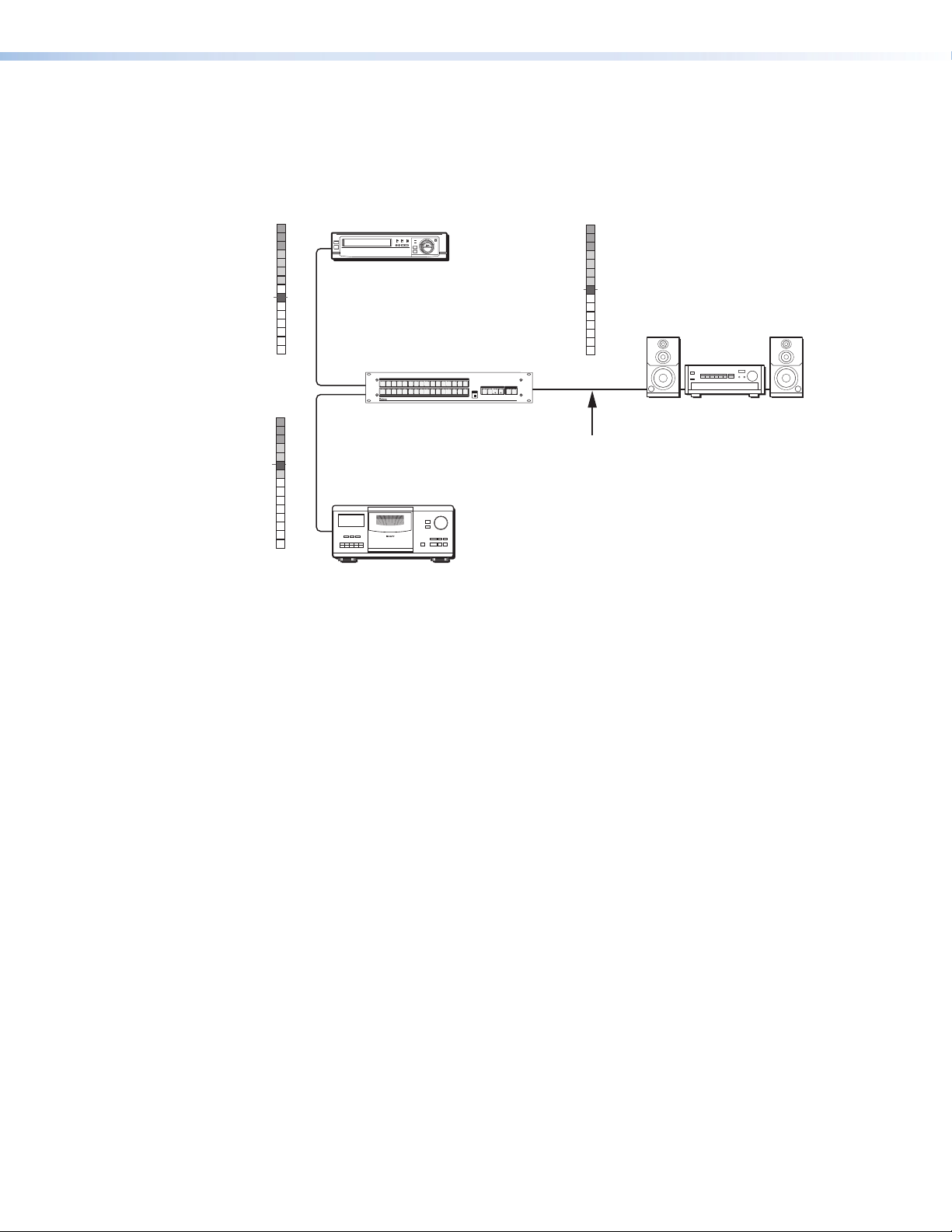
Viewing and Adjusting the Input Audio Level
Audio
Inputs
Audio
Inputs
VCR
No noticeable
volume differences
between sources
Audio System
CD Jukebox
MTPX Plus 1616
0
-3
-6
-9
-12
-15
Low Audio
Output Level
+4
+1
-2
-5
-8
-12
-18
-21
-15
-18
3 +7
6 +10
9 +13
12 +16
15 +19
18 +21
21 +24
VU dBu
0
-3
-6
-9
-12
-15
High Audio
Output Level
+4
+1
-2
-5
-8
-12
-18
-21
-15
-18
3 +7
6 +10
9 +13
12 +16
15 +19
18 +21
21 +24
VU dBu
0
-3
-6
-9
-12
-15
Output
Level
+4
+1
-2
-5
-8
-12
-18
-21
-15
-18
3 +7
6 +10
9 +13
12 +16
15 +19
18 +21
21 +24
VU dBu
AUDIO
VIDEO
I/O
CONTROL
ENTERPRESET
VIEW
ESC
1
2
34
5
6
7
8
9
10
11
12
13
14
15
16
1
2
34
5
6
7
8
9
10
11
12
13
14
15
16
INPUTS
OUTPUTS
CONFIG
MTPX PLUS SERIES
MTP MATRIX SWITCHER
The audio level of each input can be displayed and adjusted through a range of -18
dB to +24 dB to ensure that there is no noticeable volume difference among sources
(see figure 25). The audio level can be adjusted from the front panel or under remote
control. The default audio level is 0 dB.
Figure 25. Audio Gain and Attenuation
1. Press the Esc button to clear any input buttons, output buttons, or control buttons that
may be lit.
2. To enter Audio mode, press and hold the Audio button until the button begins to blink
red, then release the button.
3. Press and release an input button to select an input. The output buttons display the
audio level for the selected input; the more output LEDs lit, the greater the gain or
attenuation.
• Green output buttons indicate a gain (+) audio level.
• Red output buttons indicate an attenuation (–) level.
Audio gain and attenuation is displayed differently on different models.
• Switchers with 32 output buttons — Each output button indicates 1 dB when lit
• Switchers with 16 output buttons — Each output button indicates 1 dB when
• MTPX Plus 128 (8 output buttons) — Each output button indicates 1 dB when
4. Press and release the Esc (>) and View (<) buttons to increase and decrease the audio
level.
5. Press and release the Audio button to exit the Audio mode. The Audio button stops
steadily (see table 4 on page 49).
blinking and 2 dB when lit steadily (see table 5 on page 50).
blinking slowly, 2 dB when blinking quickly, and 3 dB when lit steadily (see table 5
on page 50).
blinking.
MTPX Plus Series • Operation 48
Page 55
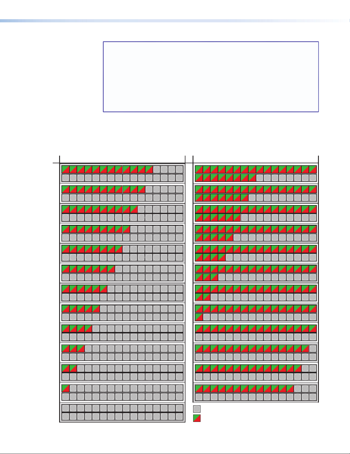
MTPX Plus 1632, 3216, 3232 MTPX Plus 1632, 3216, 3232
NOTES: • Pressing the Enter or Preset button also exits Audio mode. Pressing the
Preset button changes to Recall Preset mode.
• There is one audio level setting per input. The audio level setting is shared
by the left and right audio inputs.
• The audio level settings are stored in non-volatile memory. When power
is removed and restored, the audio level settings are retained.
• Exiting Audio mode by pressing the Audio button always returns the I/O
configuration to video and audio selected for configuration (Video and
Audio buttons lit).
Table 4. 32-output Button Audio Gain and Attenuation Display
dB dB
1 2 3 4 5 6 7 8 9 10 11 12 12345678910111213141516
12
18 19 20 21 22 23 24 25 26 27 28 29 30 31 3217
13 14 15 16
24
18 19 20 21 22 23 2417
25 26 27 28 29 30 31 32
1 2 3 4 5 6 7 8 9 10 11
11
10
18 19 20 21 22 23 24 25 26 27 28 29 30 31 3217
1 2 3 4 5 6 7 8 9 10
18 19 20 21 22 23 24 25 26 27 28 29 30 31 3217
1 2 3 4 5 6 7 8 9
9
18 19 20 21 22 23 24 25 26 27 28 29 30 31 3217
1 2 3 4 5 6 7 8
8
18 19 20 21 22 23 24 25 26 27 28 29 30 31 3217
1 2 3 4 5 6 7
7
18 19 20 21 22 23 24 25 26 27 28 29 30 31 3217
1 2 3 4 5 6
6
18 19 20 21 22 23 24 25 26 27 28 29 30 31 3217
1 2 3 4 5
5
18 19 20 21 22 23 24 25 26 27 28 29 30 31 3217
1 2 3 4
4
18 19 20 21 22 23 24 25 26 27 28 29 30 31 3217
1 2 3
3
18 19 20 21 22 23 24 25 26 27 28 29 30 31 3217
45678910 11 12 13 14 15 16
78910 11 12 13 14 15 16
6 78910 11 12 13 14 15 16
5678910 11 12 13 14 15 16
8910 11 12 13 14 15 16
910111213141516
12 13 14 15 16
11 12 13 14 15 16
10 11 12 13 14 15 16
12345678910111213141516
23
18 19 20 21 22 2317
12345678910111213141516
22
18 19 20 21 2217
12345678910111213141516
21
18 19 20 2117
12345678910111213141516
20
18 19 2017
12345678910111213141516
19
18 1917
12345678910111213141516
18
1817
12345678910111213141516
17
18 19 20 21 22 23 24 25 26 27 28 29 30 31 32
17
12345678910111213141516
16
18 19 20 21 22 23 24 25 26 27 28 29 30 31 3217
123456789101112131415
15
18 19 20 21 22 23 24 25 26 27 28 29 30 31 3217
21 22 23 24 25 26 27 28 29 30 31 32
20 21 22 23 24 25 26 27 28 29 30 31 32
19 20 21 22 23 24 25 26 27 28 29 30 31 32
24 25 26 27 28 29 30 31 32
23 24 25 26 27 28 29 30 31 32
22 23 24 25 26 27 28 29 30 31 32
16
345678910 11 12 13 14 15 16
1 2
2
18 19 20 21 22 23 24 25 26 27 28 29 30 31 3217
2 345678910 11 12 13 14 15 16
1
1
18 19 20 21 22 23 24 25 26 27 28 29 30 31 3217
12345678910 11 12 13 14 15 16
0
18 19 20 21 22 23 24 25 26 27 28 29 30 31 3217
1234567891011121314
14
18 19 20 21 22 23 24 25 26 27 28 29 30 31 3217
12345678910111213
13
18 19 20 21 22 23 24 25 26 27 28 29 30 31 3217
= unlit button
= lit button
Green indicates a positive (gain) level.
Red indicates a negative (attenuation) level.
MTPX Plus Series • Operation 49
15 16
14 15 16
Page 56

MTPX Plus 816, 168, 1616
MTPX Plus 128
61
Table 5. 8- and 16-output Button Audio Gain and Attenuation Display
dB dB
24
23
2134 5678
2134 5678
24
23
F
112134 5678910 12
112134 5678910 12
13
13
14
14
15
15
16
16
22
21
20
19
18
17
16
15
14
13
12
11
10
2134 5678
2134 567
213456
213456
213456
213456
213456
21345
21345
21345
2134 5678
2134 5678
2134 5678
9
2134 5678
8
2134 5678
F
F
S
F
S
6 7 8
6 7 8
F
6 7 8
S
7
F
7
S
7 8
7 8
7 8
22
S
21
8
20
8
19
8
18
17
16
15
14
13
12
11
10
2134 5678910
2134 5678910
2134 56789
2134 56789
2134 5678
2134 5678
2134 567
2134 567
213456
213456
1345
2
9
1345
2
8
134
2
5 6 7 8 9
9
9
8 9
8 9
7 8 9
7 8 9
6 7 8 9
6 7 8 9
10
10
10
10
10
10
10
10
10
112134 5678910
112134 5678910
11
11
1110
1110
11
11
11
11
11
11
11
11
11
12
12
12
12
12
12
12
12
12
12
12
12
12
12
12
13
13
13
13
13
13
13
13
13
13
13
13
13
13
13
14
14
14
14
14
14
14
14
14
14
14
14
14
14
14
15
15
15
15
15
15
15
15
15
15
15
15
15
15
15
16
16
16
16
16
16
16
16
16
16
16
16
16
16
16
7
2134 5678
S
6
2134 5678
5
2134 5678
F
4
2134 5678
S
3
2134 5678
2
2134 5678
F
1
2134 5678
S
0
7
6
5
4
3
2
1
0
2134
4 5 6 7 8 9
213
4 5 6 7 8 9
213
3 4 5 6 7 8 9
21
3 4 5 6 7 8 9
21
3 4 5 6 7 8 9
1
3 4 5 6 7 8 9
1
1
3 4 5
5 6 7 8 9
10
10
10
10
10
10
10
10
11
11
11
11
11
112
112
112
12
12
12
12
12
12
12
16
14
15
13
16
14
15
13
16
14
15
13
16
14
15
13
16
14
15
13
16
14
15
13
16
14
15
13
27 8 9
15 16
14
132134 5678
= Unlit button = Blinking button
= Fast blinking button= Slow blinking button
FS
= Lit button
Green indicates a positive (gain) level. Red indicates a negative (attenuation) level.
MTPX Plus Series • Operation 50
Page 57

Example 9: Viewing and adjusting an input audio level
AUDIO
AUDIO
Press and hold.
2 seconds
1 2 3 4 5 6 7 8 15 16
17 18 19 20 21 22 23 24 31 32
1 2 3 4 5 6 7 8 5 16
17 18 19 20 21 22 23 24
2 1
32
I
N
P
U
T
S
O
U
T
P
U
T
S
Press the button. It lights green.
Each output button indicates 1 dB when lit.
When the buttons are lit green, then indicate a gain (+) audio level.
When the output buttons are lit red, they indicate an attenuation (-) level.
The output buttons display the audio level and polarity (gain or attenuation)
of the selected input.
NOTE: This procedure can only be performed if the audio/RS-232 wire pair of the input
is defined as audio (see ”Defining the Audio/RS-232 Wire Pair” on page 62).
Because of the different gain and attenuation display schemes, the input audio levels that
result from the following example are shown three times:
• As displayed on a 32-output button switcher
• As displayed on a on 16-output button switcher
• As displayed on a 8-output button switchers
The 32-button drawings show the actions that led up to the display. The 16-button and
8-button drawings show the gain or attenuation display only, not the actions that caused it.
In the following example, an audio level is viewed and adjusted. The steps show the front
panel indications that result from your action.
1. Clear all selections: Press and release the Esc button.
2. Select Audio mode: Press and hold the Audio button for approximately 2 seconds
until it blinks.
3. Select an input: Press and release the Input 5 button (see figure 26).
Figure 26 through figure 28 show an audio gain level of +8 dB.
Figure 26. Select an Input
Figure 27 shows the same +8 dB level as figure 26, but displayed on a 16-output-button
switcher, such as an MTPX Plus 816.
2
1
Figure 27. Level Display on a 16-Output-Button Switcher
3 4
5
8
OUTPUTS
15
9
16
MTPX Plus Series • Operation 51
7
6
Page 58

Figure 28 shows the same +8 dB level as figure 26, but displayed on an 8-output-button
1 2 3 4 5 6 7 8 15 16
17 18 19 20 21 22 23 24 31 32
O
U
T
P
U
T
S
VIEW
Press the button.
The output buttons display the audio level and
polarity (gain or attenuation) of the selected input.
Each output button indicates 1 dB when lit.
When the buttons are lit green, they indicate a
gain (+) audio level.
When the output buttons are lit red, they indicate
an attenuation (-) level.
•
•
I / O
VIDEO AUDIO
The Audio button stops
blinking and lights steadily.
Press the button.
All input buttons and output buttons
return to unlit or background illumination.
The Video button
lights green.
MTPX Plus 128.
1
2 3
4
5
F
6 7
8
Figure 28. Level Display on an 8-Output-Button Switcher
4. Change the audio level: Press and release the View (<) button once (see figure 29) to
decrease the input audio level by 1 dB.
Press and release the View (<) button several more times (see figure 29) to decrease the
input audio level by 1 dB per button press. Note the output button indication changes
that occur each time the View (<) button is pressed.
Figure 29 through figure 31 show the result of pressing the View (<) button a total of
nine times, an audio attenuation level of –1 dB. Note that the level is now displayed in
red to indicate a negative level.
Figure 29. Adjust the Input Audio Level
Figure 30 shows the same –1 dB level as in figure 3-49, but displayed on a
16-output-button switcher, such as a MTPX Plus 1616.
2
1
4
3
6 7
5
8
OUTPUTS
15
9
16
Figure 30. Level Display on a 16-Output-Button Switcher
Figure 31 shows the same –1 dB level as in figure 3-49, but displayed on an
8-output-button MTPX Plus 128.
1
S
2 3
4
5
6 7
8
Figure 31. Level Display on an 8-Output-Button Switcher
5. Exit Audio mode: Press and release the Audio button.
MTPX Plus Series • Operation 52
Page 59

Viewing and Adjusting the Local Output Volume
The audio level of each local output can be displayed and adjusted through a range of
100% (no attenuation) to 0% (maximum [76 dB] attenuation). The audio level can be
adjusted from the front panel or under serial port, USB port, or Ethernet control. The default
volume is 100% (no attenuation).
NOTE: Output volume is protected when front panel Lock mode 2 is selected. You can
view the volume in Lock mode 2 but you cannot adjust it from the front panel
(see “Setting the Front Panel Locks (Executive Modes)” on page 59).
1. Press the Esc button to clear any input buttons, output buttons, or control buttons that
may be lit.
2. To enter Audio mode, press and hold the Audio button until the button begins to blink
red, then release the button.
3. Press and release an output button to select an output. The input buttons display the
volume level for the selected output. As a general rule, the more buttons that are lit, the
higher the volume. The fewer buttons that are lit, the lower the volume.
For a more detailed analysis of decoding the displayed value, see “Reading the
displayed volume”, on the next page.
4. Press and release the Esc (>) and View (<) buttons to increase and decrease the audio
volume.
5. Press and release the Audio button to save the audio settings and exit the Audio mode.
The Audio button stops blinking.
NOTES: • Only the volume for the local audio outputs (outputs 1 through 4 [matrix
sizes 816, 168, and 1616] or outputs 1 through 8 [matrix sizes 1632,
3216, and 3232]) is adjustable. Outputs outside the local range cannot
be selected in step 3.
• There is one audio volume level setting per local output. The audio level
setting is shared by the left and right audio inputs.
• The audio volume levels are stored in non-volatile memory. When power
is removed and restored, the audio level settings are retained.
• Exiting Audio mode by pressing the Audio button always returns the I/O
buttons to Video lit green and Audio lit red.
• Pressing the Enter or Preset button also exits Audio mode. Pressing the
Preset button changes to Recall Preset mode.
MTPX Plus Series • Operation 53
Page 60

Reading the displayed volume
This section is a detailed look at reading the output volume display on the front panel. If you
do not need to read the exact value of the volume setting, skip this section.
There are 65 steps of volume attenuation, with 1 dB per step (button push), except for 0-to-1,
which is 13 dB. At maximum attenuation, no input buttons are lit, 76 dB of attenuation is
applied, and the audio output is effectively muted. At no attenuation, all input buttons are lit
and the output volume is equal to the input signal plus any gain or attenuation that is applied
to that specific input using the input audio level adjustment (see “Viewing and Adjusting
the Input Audio Level”, on page 48). Other than the minimum and maximum volume,
the switchers indicate the volume differently, depending on number (12, 16, or 32) of input
buttons (see table 6 on the next page to read the volume display for each display scheme).
For each display scheme, the input buttons blink or light sequentially to indicate the
approximate volume of the selected output. Volume is defined as a percentage of the input
audio signal that is applied to the output. From 0% of volume, the first Esc (>) button push
applies 5.5% of the input audio signal. From 5.5% on, each Esc (>) push applies 1.5% more
of the input audio signal to the output:
• Push Esc (>) button again — 5.5% + 1.5% = 7% volume
• Switchers with 12 and 16 input buttons — The Input 1 button blinks slowly
• Switchers with 32 input buttons — The Input 1 button lights steadily
• Push Esc (>) button twice more — 7% + 1.5% + 1.5% = 10% volume
• Switchers with 12 input buttons — The Input 1 button blinks quickly.
• Switchers with 16 input buttons — The Input 1 button lights steadily
• Switchers with 32 input buttons — The Input 1 and Input 2 button light steadily
• Push Esc (>) button 19 times more — 10% + (19 times 1.5%) = 38.5% volume
• Switchers with 12 input buttons — The Input 1 through 4 buttons light steadily.
• Switchers with 16 input buttons — The Input 1 through 5 buttons light steadily
and the Input 6 button blinks
• Switchers with 32 input buttons — The Input 1 through Input 11 buttons light
steadily and the Input 12 button blinks
When all input buttons are lit for any switcher model, the audio output is 100% of the
audio input level.
Another way to view the volume level is to think in terms of the attenuation that is applied
to the output. Attenuation reduction is indicated by the lit or blinking input buttons: when
fewer input buttons are lit, attenuation is greater (and the volume is quieter).
• At minimum volume, all input buttons are unlit or background illuminated and 76 dB of
attenuation is applied to the output. The audio output is effectively muted.
• The first step of volume increase causes the Input 1 button to blink (slowly, in the
case of switchers with 12 input buttons) . Attenuation is reduced by 13 dB (63 dB of
attenuation is applied to the output).
• The second step of volume increase reduces the attenuation by an additional 1 dB
(62 dB of attenuation is applied to the output). (On switchers with 32 input buttons the
Input 1 button lights steadily.)
• Successive steps of volume increase cause consecutive input buttons to first blink
and then light steadily. (On switchers with 32 input buttons, each consecutive button
indicates a 1 dB attenuation reduction when blinking and a 2 dB attenuation
reduction when lit.)
MTPX Plus Series • Operation 54
Page 61
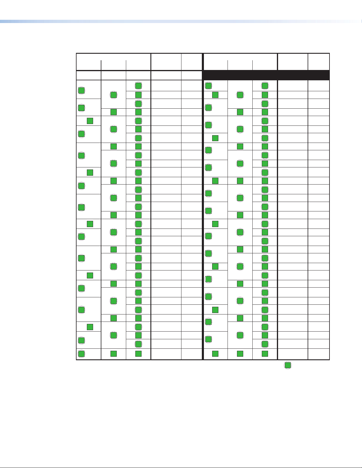
Table 6. Audio Volume Display
Highest # input button lit
Slow
blink
Fast
blink
Slow
blink
Fast
blink
2
Slow
blink
Fast
blink
3
Slow
blink
Fast
blink
4
Slow
blink
Fast
blink
5
Slow
blink
Fast
blink
16-input
switcher
None
1
1
2
2
3
3
4
4
5
5
6
6
7
7
8
8
32-input
switcher
1
1
2
2
31
3
4
4
5
5
6
6
7
7
8
8
9
9
10
10
11
11
12
12
13
13
14
14
15
15
16
16
12-input
switcher
None
1
1
2
2
3
3
4
4
5
5
6
6
dB of
attenuation
76
63
62
61
60
59
58
57
56
55
54
53
52
51
50
49
48
47
46
45
44
43
42
41
40
39
38
37
36
35
34
33
32
Output
volume
0%None
5.5%
7%
8.5%
10%
11.5%
13%
14.5%
16%
17.5%
19%
20.5%
22%
23.5%
25%
26.5%
28%
29.5%
31%
32.5%
34%
35.5%
37%
38.5%
40%
41.5%
43%
44.5%
46%
47.5%
49%
50.5%
52%
Highest # input button lit
12-input
switcher
Fast
6
blink
6 9
Slow
7
blink
Fast
7
blink
7
Slow
8
blink
Fast
8
blink
8
Slow
9
blink
Fast
9
blink
9
Slow
10
blink
Fast
10
blink
10
Slow
11
blink
Fast
11
blink
11
Slow
12
blink
Fast
12
blink
12
16-input
switcher
32-input
switcher
9
10
10
11
11
12
12
13
13
14
14
15
15
16
16
17
17
18
18
19
19
20
20
21
21
22
22
23
23
24
24
25
25
26
26
27
27
28
28
29
29
30
30
31
31
32
32
dB of
attenuation
31 53.5%
30 55%
29
28
27
26
25
24
23
22
21
20
19
18
17
16
15
14
13
12
11
10
9
8
7
6
5
4
3
2
1
0
Output
volume
56.5%
58%
59.5%
61%
62.5%
64%
65.5%
67%
68.5%
70%
71.5%
73%
74.5%
76%
77.5%
79%
80.5%
82%
83.5%
85%
86.5%
88%
89.5%
91%
92.5%
94%
95.5%
97%
98.5%
100%
= blinking LED
MTPX Plus Series • Operation 55
Page 62

For example: When lit steadily, the Input 3 button indicates the following, depending
AUDIO
AUDIO
Press and hold.
2 seconds
on the number of input buttons the switcher has:
• Switchers with 12 input buttons — 47 dB of attenuation when compared to the
Input 3 button blinking quickly (48 dB to 50 dB of attenuation).
The blinking Input 4 button (45 dB to 46 dB of attenuation) is at least 2 dB less
than the fast blinking Input 3 button (48 dB minus 46 dB) and at most 5 dB less
(50 dB minus 45 dB).
• Switchers with 16 input buttons — 52 dB of attenuation when compared to the
Input 3 button blinking (53 dB to 55 dB of attenuation). The blinking Input 4 button
(49 dB to 51 dB of attenuation) is at least 2 dB less than the blinking Input 3 button
(53 dB minus 51 dB) and at most 6 dB less (55 dB minus 49 dB).
• Switchers with 32 input buttons — 58 dB of attenuation when compared to the
Input 3 button blinking (59 dB of attenuation). The blinking Input 4 button (57 dB
of attenuation) is 6 dB less than the steadily-lit Input 2 button (60 dB minus 57 dB).
• On switcher with 32 input buttons, the volume indications of the buttons are
additive.
For example: Input 1 lit (23 dB [22 dB + 1 dB] of attenuation reduction), Input
2 lit (2 dB [1 dB + 1 dB] of attenuation reduction), and Input 3 blinking (1 dB of
attenuation reduction) indicate that the output attenuation has been reduced by a
total of 25 dB (22 dB + 2 dB + 1 dB = 25 dB).
• At full volume, no attenuation is applied to the output and all input buttons are lit
steadily.
Example 10: Viewing and adjusting a local output volume level
In the following example, the audio output volume is viewed and adjusted. The steps show
the front panel indications that result from your action.
Because of the different volume display schemes, the output audio levels that result from the
following example are shown three times:
• As displayed on a 32-input button switcher
• As displayed on a on 16-input button switcher
• As displayed on a 8-input button switchers
The 32-button drawings show the actions that led up to the display. 16-button and 8-button
drawings show the volume display only, not the actions that caused it.
1. Clear all selections: Press and release the Esc button.
2. Select Audio mode: Press and hold the Audio button for approximately 2 seconds
until it blinks.
MTPX Plus Series • Operation 56
Page 63

3. Select an output: Press and release the output 1 button.
1 2 6
17 18 12
1 2 3 4 12 13 14 15 16
17 18 19 27 28 29 30 31 32
•
•
O
U
T
P
U
T
S
I
N
P
U
T
S
Each lit input button beyond input 1 indicates that 3 percent of the total input volume
is applied to the output. The flashing button indicates an additional 1.5 percent.
39 dB attenuation
41.5% volume
Press the button.
It lights green
In figure 32 through figure 34, the lit or blinking input buttons indicate 41.5 percent of
the applied audio input. The unlit input buttons indicate an audio volume attenuation of
39 dB. Figure 33 and figure 34 show the same 41.5 percent, 39 dB volume.
Figure 32. Select Output 1
Figure 33 shows the same volume as figure 32, but displayed on a 16-input-button
switcher, such as an MTPX Plus 1616.
39 dB attenuation,
41.5% volume
INPUTS
1 3 4 5 6 7 8 9
10 14
12
11 162
13 15
Figure 33. Volume Display on a 16-Input-Button Switcher
Figure 34 shows the same volume as figure 32, but displayed on a 12-input-button
MTPX Plus 128.
39 dB attenuation,
41.5% volume
I
N
P
U
1
T
Figure 34. Volume Display on a 12-Input-Button Switcher
2 3
4
5
S
6 7
8
9
10
11
12
NOTE: Volume is protected when front panel Lock mode 2 is selected. You can
view the volume in Lock mode 2 but you cannot change it from the front
panel (see “Setting the Front Panel Locks (Executive Modes)” on
page 59).
If front panel Lock mode 2 is selected and you try to perform step 4, the
actions are ignored and the Enter, Video, and Audio buttons flash.
MTPX Plus Series • Operation 57
Page 64

4. Change the volume: Press and release the Esc (>) button once (see figure 35) to
ESC
1 2 3 4 12 13 14 15 16
17 18 19 27 28 29 30 31 32
I
N
P
U
T
S
Decrease the audio
attenuation (thereby
increasing the audio level)
that is applied to the
output volume level by
1 dB per button push.
Each lit input button beyond input 1 indicates that 3 percent of the total input is applied to the output.
26 dB attenuation,
61% volume
Press the button
26 dB attenuation
–26 dB attenuation,
I / O
VIDEO AUDIO
The Audio button stops
blinking and lights steadily.
Press the button.
All input buttons and output buttons
return to unlit or background illumination.
The Video button
lights green.
increase the volume by 1.5%.
Press and release the Esc (>) button several more times (figure 3-57) to increase the
volume by 1.5% per button press. Note the input button indication changes that occur
each time the Esc (>) button is pressed and released.
NOTE: You can press and hold the Esc (>) or View (>) button to ramp the level up
or down by 3 dB per second to the high or low limit.
Figure 35 show the result of pressing the Esc (
) button a total of 13 times. In figure 35
>
through figure 37, the lit or blinking input buttons indicate 61 percent of the applied
audio input. The unlit input buttons indicate an audio volume attenuation of 26 dB.
Figure 35. Adjust the Output Audio Volume
Figure 36 shows the same volume (61%) as in figure 35, but displayed on a
16-input-button switcher, such as an MTPX Plus 168.
61% volume
INPUTS
1 3 4 5 6 7 8 9
Figure 36. Volume Display on a 16-Input-Button Switcher
10 14
12
11 162
13 15
Figure 37 shows the same volume (61%) as in figure 35, but displayed on a
12-input-button MTPX Plus 128.
I
N
P
U
1
T
2 3
4
5
Figure 37. Volume Display on a 12-Input-Button Switcher
5. Exit Audio mode: Press and release the Audio button to (figure 3-60).
61% volume
6 7
8
F
9
10
11
12
MTPX Plus Series • Operation 58
Page 65

Setting the Front Panel Locks (Executive Modes)
The matrix switcher has three levels of front panel security lock that limit the operation of
the switcher from the front panel. The three levels are:
• Lock mode 0 — The front panel is completely unlocked. All front panel functions are
available.
• Lock mode 1 — All changes are locked from the front panel (except for setting Lock
mode 2). Some functions can be viewed.
• Lock mode 2 — Basic functions are unlocked. Advanced features are locked and can be
viewed only.
Basic functions consist of:
• Making ties
• Saving and recalling presets
• Setting input audio gain and attenuation
• Changing Lock modes
Advanced functions consist of:
• Creating I/O groups
• Setting audio output mutes
• Setting audio output volume
• Setting the rear panel remote port protocol and baud rate
• Setting the audio/RS-232 input format (audio or RS-232)
NOTE: The switcher is shipped from the factory in Lock mode 2.
Selecting Lock mode 2 or toggling between mode 2 and mode 0
NOTE: If the switcher is in Lock mode 0 or mode 1, this procedure selects mode 2.
If the switcher is in Lock mode 2, this procedure selects mode 0 (unlocks the
Toggle the lock on and off by pressing and holding the Enter button, the Video button, and
the Audio button simultaneously for approximately 2 seconds (see figure 38).
Press and hold the Enter, Video, and Audio
buttons simultaneously to turn on Lock mode 2
or to toggle between mode 2 and mode 0.
ENTER
Figure 38. Toggle Front Panel Lock Between Mode 2 and Mode 0
switcher).
I / O
VIDEO AUDIO
2 seconds
ENTER
I / O
VIDEO AUDIO
The Enter, Video,
and Audio buttons
blink twice to indicate
the mode change.
Release the buttons.
MTPX Plus Series • Operation 59
Page 66

Selecting Lock mode 2 or toggling between mode 2 and mode 1
NOTE: If the switcher is in Lock mode 0 or mode 1, this procedure selects mode 2.
If the switcher is in Lock mode 2, this procedure selects mode 1.
Toggle the lock on and off by pressing and holding the Video button and the Audio button
simultaneously for approximately 2 seconds (see figure 39).
Press and hold the Video and Audio buttons
simultaneously to turn on Lock mode 2 or to
toggle between mode 1 and mode 2.
I / O
VIDEO AUDIO
2 seconds
I / O
VIDEO AUDIO
The Video and Audio
buttons blink twice to
indicate the mode
change.
Release the buttons.
Figure 39. Toggle Front Panel Lock Between Mode 2 and Mode 1
Performing a System Reset from the Front Panel
The front panel reset is identical to issuing the EZXXX} SIS command (see the
“Programming Guide” section). A system reset performs the following functions:
NOTE: System reset does not reset the Internet protocol (IP) settings or replace user-
installed firmware.
• Clears all ties and presets
• Clears all audio or RS-232 mutes
• Resets all I/O grouping
• Resets all input level/peaking to zero
• Resets all input and output skew adjustments to zero.
• Resets all output pre-peaking to off
• Disables all RS-232 output inserts
• Sets all audio/RS-232 wire pair inputs to audio
• Resets all input audio levels to unity gain (0 dB)
• Sets all output volume levels to 100% (0 dB of attenuation)
NOTE: The system reset clears most image and audio adjustments. If you want to save
these settings, use the Matrix Switchers Control Program and the File > Save
MATRIX settings as...
selection before you perform this reset (see the
“Matrix Software” section.
MTPX Plus Series • Operation 60
Page 67
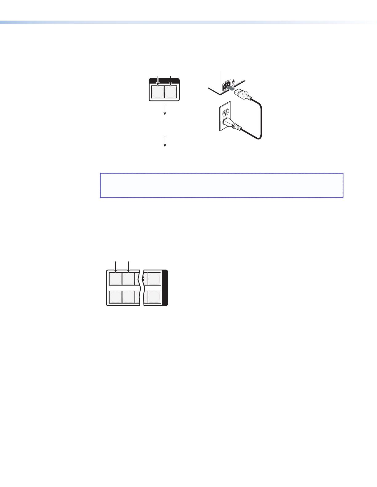
Reset the switcher to the factory default settings by pressing and holding the Video button
I / O
VIDEO AUDIO
Press and hold the Video and Audio
buttons simultaneously while you
apply power to the switcher.
Release the Video and Audio buttons.
Power
The switcher flashes
the button indicators
and then turns them off.
Continue to hold the Video and Audio
buttons until all input and output buttons
return to unlit and the Video and Audio
buttons turn on.
1 2 3 16
17 18 19 32
I
N
P
U
T
S
Press and hold the buttons.
After the illumination status of the
buttons change (after approximately
2 seconds), release the buttons.
and Audio button simultaneously while you apply AC power to the switcher (see figure 40).
Figure 40. System Reset
NOTE: If background illumination was turned on before the reset, the I/O and control
buttons are unlit after the reset. But, when you cycle power, background
illumination returns to as selected.
Background Illumination
The buttons on the front panel can be set to provide amber background illumination at
all times or the background illumination can be turned off. To toggle the background
illumination on or off, press and hold the Input 1 and Input 2 buttons simultaneously for
approximately 2 seconds (see figure 41).
Figure 41. Toggle Background Illumination on or off
MTPX Plus Series • Operation 61
Page 68

Defining the Audio/RS-232 Wire Pair
2 seconds
I / O
VIDEO AUDIO
C O N T R O L
PRESET
ENTER
ESCVIEW
C O N T R O L
PRESET
ENTER
ESCVIEW
2
1 3 4 5 6 7 8 9
16
INPUTS
Press and hold the buttons.
All Control buttons light with
one flashing.
Both I/O buttons light
with one flashing.
Unlit input buttons indicate that the audio/RS-232 twisted wire pair of the input is configured as audio.
Red input buttons indicate that the audio/RS-232 twisted wire pair of the input is configured as RS-232.
Unlit Unlit Unlit Unlit Unlit Unlit
Red
Unlit Unlit Unlit
NOTE: The Control and I/O buttons indicate the baud rate and protocol. See “Selecting
the Rear Panel Remote Port Protocol and Baud Rate”, later in this section.
2
1 3 4 5 6 7 8 9
16
INPUTS
Press the button to toggle the audio/RS-232 wire
pair configuration (to audio, in this example).
C O N T R O L
PRESET
ENTER
I / O
VIDEO AUDIO
ESCVIEW
5
All Control, I/O, Input, and Output buttons
return to unlit or background illumination.
Press an
output button.
NOTE: The TP audio/RS-232 input wire pair configurations are protected when front
panel Lock mode 2 is selected. You can view the configurations in Lock mode 2
but you cannot adjust them from the front panel (see “Setting the Front
Panel Locks (Executive Modes)” on page 59).
The switcher is compatible with MTPs that transmit and receive mono audio and those that
transmit and receive RS-232 serial data. You must configure the switcher for the appropriate
audio/RS-232 input for each TP input. The audio/RS-232 settings for each TP input can be
viewed and changed from the front panel.
View and configure the TP input audio/RS-232 configuration settings for the switcher as
follows:
1. Select Serial Port and Audio/RS-232 Input Configuration mode: Simultaneously
press and hold all Control buttons (Enter, Preset, View, and Esc).
2. Release the Control buttons.
NOTE: If front panel Lock mode 2 is selected and you try to perform step 3, the
actions are ignored and the Enter, Video, and Audio buttons flash (see
“Setting the Front Panel Locks (Executive Modes)” on page 59).
3. Change the audio/RS-232 wire pair configuration for an input: Press and release
the input button to toggle the configuration for that input.
4. Exit the Serial Port and Audio/RS-232 Input Configuration mode: Press and release
an output button.
MTPX Plus Series • Operation 62
Page 69
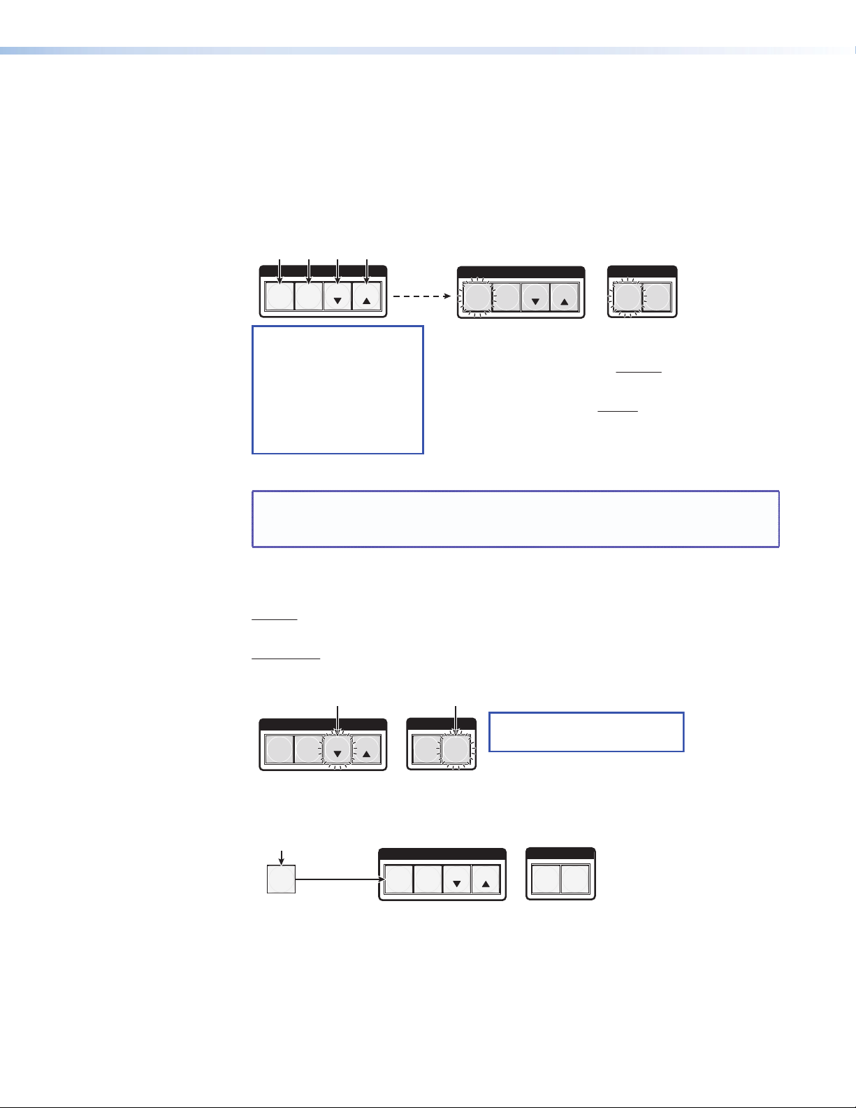
Selecting the Rear Panel Remote Port Protocol and Baud Rate
2 seconds
I / O
VIDEO AUDIO
•
•
C O N T R O L
PRESET
ENTER
ESCVIEW
C O N T R O L
PRESET
ENTER
ESCVIEW
The flashing Control button indicates the baud rate as follows:
Enter — 9600 Preset — 19200
View — 38400 Esc — 115200
The flashing I/O button indicates the protocol as follows:
Video — RS-232 Audio — RS-422/RS-485
In this example, the port is set to RS-232 at 9600 baud.
All Control buttons light with
one flashing.
Both I/O buttons light
with one flashing.
Press and hold the buttons.
NOTES: • The Input buttons indicate
the configuration of the
secondary wire pairs. See
“Selecting the TP wire
pair secondary input”,
earlier in this section.
• The MTPX Plus 128 is RS-232
only. For this switcher, the
Video and Audio button
indications have no
meaning.
C O N T R O L
PRESET
ENTER
I / O
VIDEO AUDIO
ESC VIEW
Press and release the button(s) to configure the port as
follows:
Baud rate:
Enter — 9600 Preset — 19200
View — 38400 Esc — 115200
Serial protocol:
Video — RS-232 Audio — RS-422/RS-485
The selected buttons blink and the others remain lit.
In this example, the port is set to RS-422 at 38400 baud.
NOTE: The MTPX Plus 128 is RS-232 only.
For this switcher, the Video and Audio
button indications have no meaning.
C O N T R O L
PRESET
ENTER
I / O
VIDEO AUDIO
ESCVIEW
5
All Control, I/O, Input, and Output buttons
return to unlit or background illumination.
Press an
output button.
All switchers can operate at the 9600, 19200, 38400, and 115200 baud rate. Switchers
other than the MTPX Plus 128 can support either RS-232 or RS-422 serial communication
protocol. The settings of these variables can be viewed and changed from the front panel.
View and configure the serial communications settings as follows:
1. Select Serial Port and Audio/RS-232 Input Configuration mode: Simultaneously
press and hold all Control buttons (Enter, Preset, View, and Esc).
2. Release the Control buttons.
NOTE: If front panel Lock mode 2 is selected and you try to perform step 3, the
actions are ignored and the Enter, Video, and Audio buttons flash (see
“Setting the Front Panel Locks (Executive Modes)” on page 59).
3. Change a value: Press and release the button that relates to the desired value.
4. Exit the Serial Port and Audio/RS-232 Input Configuration mode: Press and release
an output button.
MTPX Plus Series • Operation 63
Page 70

Rear Panel Operations
Power
RESET
Press and hold the button
while you apply power.
Release the Reset button.
The switcher flashes the front panel
button indicators green, red, and
amber and then turns them off.
Continue to hold the Reset button until
all input and output buttons return to
either unlit or to background illumination
and the Video and Audio buttons turn on.
The rear panel has a Reset button that initiates four levels of resets (numbered 1, 3, 4, and 5
for the sake of comparison with an Extron IPL product). The Reset button is recessed, so use
a small screwdriver, a pointed stylus, or a ballpoint pen.
See table 7 on the next page for a summary of the modes.
CAUTION: Review the reset modes carefully. Using the wrong reset mode may result
NOTE: The reset modes listed on the next page close all open IP and Telnet connections
Performing a Hard Reset (Reset 1)
The hard reset function restores the switcher to the base firmware that it was shipped with.
After a hard reset, events do not automatically start, but user settings and files are restored.
Perform a hard reset as follows:
NOTE: The hard reset restores the factory-installed firmware. The switcher reverts
in unintended loss of flash memory programming, port reassignment, or a
controller reboot.
and close all sockets. Also, the following modes are separate functions, not a
continuation from Mode 1 to Mode 5.
to that factory firmware the next time power is cycled off and on unless a
firmware update is performed before the power cycle.
1. If necessary, turn off power to the switcher.
2. Press and hold the Reset button on the rear panel while you apply AC power to the
switcher (see figure 42).
Figure 42. Hard Reset
MTPX Plus Series • Operation 64
Page 71

Table 7.
Mode Activation Result Purpose/Notes
1 Hold down the recessed Reset button
while applying power to the switcher.
NOTE: After a mode 1 reset is
performed, update the
switcher firmware to the
latest version. Do not
operate the switcher
firmware version that
results from the mode 1
reset. If you want to
use the factory default
firmware, you must
upload that version
again (see the “Matrix
Software”section for
details on uploading
firmware).
Reset Mode Comparison/Summary
The switcher reverts to the factory default
firmware. Event scripting will not start if the
switcher is powered on in this mode. All user files
and settings (such as drivers, adjustments, and IP
settings) are maintained.
NOTE: If you do not want to update
firmware, or you performed a mode 1
reset by mistake, cycle power to the
switcher to return to the firmware
version that was running before
the mode 1 reset. Use the 0Q SIS
command to confirm that the factory
default firmware is no longer running
(look for the asterisk [*] following the
version number.
Use mode 1 to revert
to the factory default
firmware version if
incompatibility issues
arise with user-loaded
firmware.
3 Hold down the Reset button for about 3
seconds, until the Reset LED blinks once,
then press and release Reset (<1 second)
within 1 second.
4 Hold down the Reset button for about
6 seconds, until the Reset LED blinks
twice (once at 3 seconds and again at 6
seconds). Then press and release Reset
(<1 second) within 1 second.
5 Hold down the Reset button for about
9 seconds, until the Reset LED blinks
three times (once at 3 seconds, again
at 6 seconds, and then again at 9
seconds). Then press and release Reset
(<1 second) within 1 second.
NOTE: Mode 5 reset clears
most adjustments. To
save these settings,
use the Windows-
based Matrix Switchers
Control Program and the
File
>
Save MATRIX
settings as...
selection before you
perform this reset (See
the “Matrix Software”
section.
Mode 3 turns events on or off. During resetting,
the Reset LED flashes 2 times if events are starting, 3
times if events are stopping.
Mode 4:
•
Enables ARP capability.
• Sets the IP address to the factory default.
• Sets the subnet address to the factory default.
• Sets the gateway address to the factory default.
• Sets port mapping to the factory default.
• Turns DHCP off.
• Turn events off.
The Reset LED flashes four times in quick succession
during the reset.
Mode 5 performs a complete reset to factory
defaults (with the exception of the firmware):
• Does everything mode 4 does.
• Resets most all real time adjustments, including:
clears all ties and presets,
clears all audio or RS-232 mutes,
clears all I/O grouping,
clears all input level/peaking,
clears all skew adjustments,
clears all output pre-peaking,
disables all RS-232 output inserts,
sets all audio/RS-232 wire pairs to audio,
clears all audio settings.
• Resets all IP options.
• Removes/clears all files for the switcher.
The reset LED flashes four times in quick succession
during the reset.
Mode 3 is useful for
troubleshooting.
Mode 4 enables you
to set IP address
information using ARP
and the MAC address.
Mode 5 is useful if
you want to start over
with configuration and
uploading or to replace
events.
MTPX Plus Series • Operation 65
Page 72

Performing Soft System Resets (Resets 3, 4, and 5)
I / O
VIDEO AUDIO
RESET
RESET
RESET
I / O
VIDEO AUDIO
RESET
RESET
RESET
I / O
VIDEO AUDIO
RESET
RESET
RESET
Release, then immediately
press and release again.
Release, then immediately
press and release again.
IP Settings
Reset
6 seconds
Absolute Reset
9 seconds
Press and hold
the Reset button.
3 seconds
Events Reset
(Mode 4)
(Mode 5)
(Mode 1)
Front panel I/O buttons flash once.
Reset LED flashes once.
Release, then immediately
press and release again.
Reset LED flashes twice.
Press and hold
the Reset button.
Press and hold
the Reset button.
Reset LED flashes
three times.
Front panel I/O buttons flash twice.
Front panel I/O buttons flash three times.
Perform a soft reset of the switcher as follows:
1. Use a small screwdriver to press and hold the rear panel Reset button until the front
panel Video and Audio buttons blink the number of times for the desired reset: once
(events reset), twice (system reset), or three times (absolute reset) (see figure 43).
Figure 43. Soft System Resets
2. Release the Reset button and then immediately press and release the Reset button
again. Nothing happens if the second momentary press does not occur within 1 second.
MTPX Plus Series • Operation 66
Page 73

Optimizing the Audio
Each audio level for each input can be adjusted within a range of -18 dB to +24 dB, so
there are no noticeable volume differences between sources and for the best headroom
and signal-to-noise ratio. The volume for each local audio output can be adjusted from full
loudness to effectively muted. Adjust the levels as follows:
1. Connect audio sources to all desired inputs and connect the local audio outputs to
output devices such as audio players. See “Signal inputs”, in the “Installation” section.
For best results, wire all of the inputs and the outputs balanced.
2. Power on the audio sources, the switcher, and the audio players.
3. Switch among the inputs (see “Creating a configuration”, on page 31), listening to
the audio with a critical ear or measuring the output audio level with test equipment,
such as a VU meter.
4. As necessary, adjust the input audio level of each input (see “Viewing and Adjusting
the Input Audio Level”, on page 48) so that the approximate output level is the same
for all selected inputs.
5. Tie an audio input to each local audio output.
6. As necessary, adjust the output audio level of each output (see “Viewing and
Adjusting the Local Output Volume”, on page 53).
Video Adjustments
Image adjustments are available via SIS commands, the Matrix Switchers Control Program,
and the built-in HTML pages. See “Optimizing the Video” in the “Matrix Software”
section.
Troubleshooting
This section recommends what to do if you have problems operating the switcher.
1. Ensure that all devices are plugged in and powered on.
2. Check to see if one or more outputs are muted.
3. Ensure an active input is selected for output on the switcher.
4. Ensure that the proper signal format is supplied.
5. Check the cabling and make corrections as necessary.
6. Call the Extron S3 Sales and Technical Support Hotline if necessary. See the end of this
guide for the phone number in your region of the world.
MTPX Plus Series • Operation 67
Page 74

Configuration Worksheets
1 2345678
12345678
91011
11
12 13
10
9
Input sources
Output destinations
Preset # Title: Video: Audio:
Fill in the preset number and use colors, dashes, etc., to make connecting lines.
Indicate if the configuration is for video, audio , or both.
Classroom
#1 VCR
USP 405
Audio
CD
PC 2
RGB 202
PC 1
RGB 202
Weekly status mtg 3
Camera
#2
Camera/
mic - Main
podium
Main hall
FP #1
Main hall
FP #2
Podium
monitor
Sound
system
#1
Sound
system
#2
VCR
(VSC 500)
DA 6
Classroom
#2 VCR
USP 405
Laptop
RGB 202
Rack DVD
(USP 405)
VTG 300
Rather than trying to remember the configuration for each preset, use worksheets to
record this information. Make copies of the blank worksheet on page 71 (32-input button
and -output button switchers) and page 72 (16-button and 12-button switchers) and use
one for each preset configuration. Cross out all unused or inactive inputs and outputs. Use
different colors for video and audio.
NOTE: All of the equipment in the following examples is connected through the
appropriate MTP transmitter or receiver.
Worksheet Example 1: System equipment
Figure 44 shows a portion of a worksheet for an MTPX Plus 1616 in a fictional organization
with the system hardware annotated. Inputs 10, 11, and 13 have no connection in this
organization, so they are crossed out on the worksheet. Similarly, outputs 7 and 9 through
16 are crossed out.
Figure 44. Worksheet Example 1: System Equipment
Inputs include PCs, an audio CD player, cameras, and an Extron VTG 300. Output devices
include monitors, projectors, a stereo, and a VCR for recording presentations.
The VTG 300 video test generator connected to input 12 enables a video test pattern to be
sent to one, several, or all output devices for problem isolation or adjustment purposes. An
audio test tape or CD could be used in a similar manner to check out the audio components.
MTPX Plus Series • Operation 68
Page 75

Worksheet Example 2: Daily Configuration
1 2345678
12345678
91011
11
12 13
10
9
Input sources
Output destinations
Preset # Title: Video: Audio:
Fill in the preset number and use colors, dashes, etc., to make connecting lines.
Indicate if the configuration is for video, audio , or both.
Classroom
#1 VCR
USP 405
Audio
CD
PC 2
RGB 202
PC 1
RGB 202
Weekly status mtg 3
Camera
#2
Camera/
mic - Main
podium
Main hall
FP #1
Main hall
FP #2
Podium
monitor
Sound
system
#1
Sound
system
#2
VCR
(VSC 500)
DA 6
Classroom
#2 VCR
USP 405
Laptop
RGB 202
Rack DVD
(USP 405)
VTG 300
Figure 45 continues from worksheet example 1 by showing the video and audio ties that
make up the configuration of preset 1. Black lines shows video ties and red lines show the
audio ties.
Figure 45. Worksheet Example 2: Daily Configuration
In this example:
• The image of the presenter, from the main podium camera (input 1), is:
• Displayed in the main hall (output 1)
• Displayed in the lobby via a distribution amplifier (output 8)
• Tied to the VCR (output 6)
• The presenter has a presentation on her laptop computer (input 4) that is:
• Displayed in the main hall (output 2)
• Displayed locally on the podium (output 3)
• The audio from the microphone the presenter uses (input 3) is:
• Played in the hall (output 1)
• Played in the conference room (output 4)
• Sent to the VCR (output 6)
• Classical music from the CD player (input 5) is:
• Played in the background in the main hall on sound system #2 (output 5)
• Played in the lobby via a distribution amplifier (output 8)
MTPX Plus Series • Operation 69
Page 76

Worksheet Example 3: Test configuration
1 2345678
12345678
91011
11
12 13
10
9
Input sources
Output destinations
Preset # Title: Video: Audio:
Fill in the preset number and use colors, dashes, etc., to make connecting lines.
Indicate if the configuration is for video, audio , or both.
Classroom
#1 VCR
USP 405
Audio
CD
PC 2
RGB 202
PC 1
RGB 202
Weekly status mtg 3
Camera
#2
Camera/
mic - Main
podium
Main hall
FP #1
Main hall
FP #2
Podium
monitor
Sound
system
#1
Sound
system
#2
VCR
(VSC 500)
DA 6
Classroom
#2 VCR
USP 405
Laptop
RGB 202
Rack DVD
(USP 405)
VTG 300
The A/V system in our fictional organization needs to be fine tuned on a regular basis.
Figure 46 shows a typical test configuration, with an Extron video test generator (input 12)
generating a test pattern to all monitors (outputs 1, 2, 3, and 8). Sound checks are run from
the CD player (input 5) to all audio systems (outputs 1, 2, 4, 5, and 8).
Figure 46. Worksheet Example 3: Test Configuration
MTPX Plus Series • Operation 70
Page 77
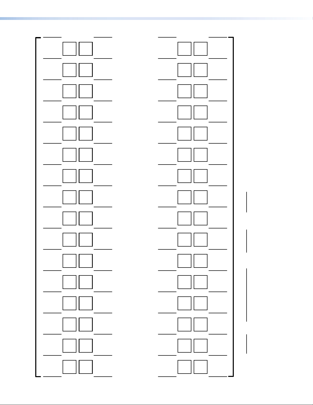
1 2 345678 910111213141516
26 27 28 29 30 31 32
Input sources
Output destinations
Preset # Title: Video: Audio:
Fill in the preset number and use colors, or dashes, etc. to mak e connecting lines .
Indicate if the configuration is for Video, Audio, or both.
1 2 345678 910111213141516
26 27 28 29 30 31 32
17 18 19 20 21 22 23 24 25
17 18 19 20 21 22 23 24 25
32-button Switchers Configuration Worksheet
MTPX Plus Series • Operation 71
Page 78
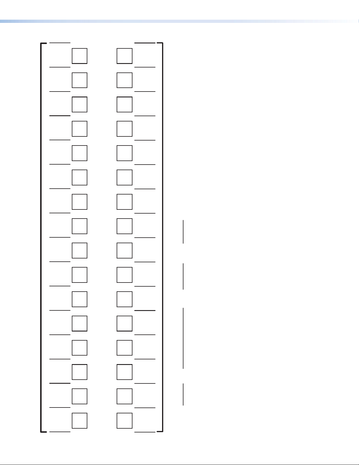
12 13 14 15 16
11
10 12 13 14 15 16
91011
9
Input sources
Output destinations
16-button Switchers Configuration Worksheet
1 2345678
12345678
Preset # Title: Video: Audio:
Fill in the preset number and use colors, or dashes, etc. to mak e connecting lines .
Indicate if the configuration is for video , audio , or both.
MTPX Plus Series • Operation 72
Page 79

Programming Guide
This section describes the operation of the MTPX Plus Matrix Switchers via SIS commands,
including:
• Local Host-Control Ports
• Ethernet (LAN) Port
• Host-to-Switcher Instructions
• Switcher-Initiated Messages
• Switcher Error Responses
• Using the Command/Response Tables
• Command/Response Table for SIS Commands
• Command Response Table for IP-specific SIS Commands
• Special Characters
MTPX Plus Series • Programming Guide 73
Page 80

Local Host-Control Ports
The switcher has two local ports that can be directly connected to a host device such as
a computer running the Extron DataViewer utility or the HyperTerminal utility, an RS-232
capable PDA, or a control system. These ports make remote control of the switcher possible
using a direct connection. The local ports are:
NOTES: • The rear panel and front panel ports are independent of one another. A
front panel Configuration port connection and a rear panel Remote port
connection can be active at the same time.
• The serial port protocol of both Remote ports and the 2.5 mm stereo jack
Configuration port is:
• 9600 baud • No parity • 8-bit
• No flow control • 1 stop bit
• See “Selecting the Rear Panel Remote Port Protocol and Baud Rate“,
in the “Operation” section to configure the rear panel Remote port from the
front panel.
• Extron recommends leaving the serial ports at 9600 baud only.
• The rear panel Remote (serial) port (see “Remote Connection“ in the “Installation”
section)
• MTPX Plus 128 — An RS-232 only port, a 3-pole captive screw connector
• All other MTPX Plus models — An RS-232 / RS-422 port, a 9-pin D female
connector
• The front panel Configuration port (see “Front Panel Configuration Port“ in the
“Installation” section)
• MTPX Plus 128 — A mini USB B port. A standard USB cable and the Extron
DataViewer utility, version 2.0 or newer, can be used for connection to the
Configuration port.
NOTE: Before you use the MTPX Plus 128 Configuration (USB) port for
the first time, you need to install and activate the USB driver on
your computer. The simplest way to do this is to install version 8.0
or newer of the Matrix Switchers Control Program and then run
the Found New Hardware Wizard (see “Installing the Software“
and “Activating a USB port for the first time“ in the “Matrix
Software“ section).
• All other MTPX Plus models — A 2.5 mm mini stereo jack (RS-232 only) port
NOTE: The optional 9-pin D to 2.5 mm mini jack TRS RS-232 cable, part
#70-335-01 can be used for connection to the Configuration port.
MTPX Plus Series • Programming Guide 74
Page 81

Ethernet (LAN) Port
The Ethernet cable can be terminated as a straight-through cable or a crossover cable and
must be properly terminated for your application (see “Ethernet Connection“ in the
“Installation” section).
• Crossover cable — Direct connection between the computer and the MTPX Plus
switcher.
• Patch (straight-through) cable — Connection of the MTPX Plus switcher to an
Ethernet LAN.
Default IP addresses
To access the MTPX Plus switcher via the LAN port, you need the IP address for the unit, and
may need the subnet mask and the gateway address. If the IP address has been changed
to an address comprised of words and characters, you can determine the actual numeric IP
address using the ping (ICMP) utility (see “Ethernet Link” on page 146 for more details). If
the addresses have not been changed, the factory-specified defaults are:
• IP address 192.168.254.254 • Subnet mask 255.255.0.0
• Gateway address 0.0.0.0
Establishing a Connection
Establish a network connection to an MTPX Plus switcher as follows:
1. Open a TCP socket to port 23 using the IP address of the switcher.
NOTE: If the local system administrators have not changed the value, the factory-
specified default, 192.168.254.254, is the correct value for this field.
The switcher responds with a copyright message including the date, the name of the
product, firmware version, part number, and the current date/time.
NOTES: • If the switcher is not password-protected, the device is ready to accept
• If the switcher is password-protected, a password prompt appears below
2. If the switcher is password protected, enter the appropriate administrator or user
password.
If the password is accepted, the switcher responds with Login User or Login
Administrator
If the password is not accepted, the Password prompt reappears.
SIS commands immediately after it sends the copyright message.
the copyright message.
.
Connection Timeouts
The Ethernet link times out after a designated period of time of no communications. By
default, this timeout value is set to five minutes but the value can be changed. See the
Configure port timeout SIS commands on page 95.
NOTE: Extron recommends leaving the default timeout at 5 minutes and periodically
issuing the Query (Q) command to keep the connection active. If there are long
idle periods, Extron recommends disconnecting the socket and reopening the
connection when another command must be sent.
MTPX Plus Series • Programming Guide 75
Page 82

Number of Connections
An MTPX Plus switcher can have up to 200 simultaneous TCP connections, including all http
sockets and telnet connections. When the connection limit is reached, the switcher accepts
no new connections until some have been closed. No error message or indication is given
that the connection limit has been reached. To maximize performance of an IP Link device,
the number of connections should stay low and unnecessary open sockets should be closed.
Using Verbose Mode
Telnet connections to an MTPX Plus switcher can be used to monitor for changes that
occur on the switcher, such as front panel operations and SIS commands from other telnet
sockets or a serial port. For a telnet session to receive change notices from the switcher, the
telnet session must be in verbose mode 1 or 3. See the Verbose Mode SIS command on
page 95. In verbose mode 3, the telnet socket reports changes in messages that resemble
SIS command responses.
Host-to-Switcher Instructions
The switcher accepts SIS (Simple Instruction Set) commands through the RS-232 port. SIS
commands consist of one or more characters per command field. They do not require any
special characters to begin or end the command character sequence. Each switcher response
to an SIS command ends with a carriage return and a line feed (CR/LF = ]), which signals
the end of the response character string. A string is one or more characters.
Switcher-initiated Messages
When a local event such as a front panel operation or an IR 501 command string occurs, the
switcher responds by sending a message to the host. The switcher-initiated messages are
listed below (underlined).
The switcher does not expect a response from the host, but, for example, the host program
might request a new status.
(C) COPYRIGHT 20yy, Extron Electronics MTPX, Vx.xx,
60-nnn-01 {day,date, time}
The switcher initiates the copyright message when it is first powered on or when a
connection via Internet protocol (IP) is established. Vx.xx is the firmware version number and
60-nnnn-01 is the switcher part number.
NOTE: {Day, date, time} are only reported if the connection is via the LAN port.
Password:
The switcher initiates the password message immediately after the copyright message when
the controlling system is connected using TCP/IP or Telnet and the switcher is password
protected. This message means that the switcher requires an administrator or user level
password before it will perform the commands entered via this link. The switcher repeats
the password message response for every entry other than a valid password until a valid
password is entered.
Login Administrator
]
Login User
]
The switcher initiates the login message when a correct administrator or user password has
been entered. If the user and administrator passwords are the same, the switcher defaults to
administrator privileges.
]
]
]
]
MTPX Plus Series • Programming Guide 76
Page 83

Qik
]
The switcher initiates the Qik message when a front panel tie creation has occurred.
Sprnn
]
The switcher initiates the Spr message when a memory preset has been saved from the front
panel. “nn” is the preset number.
Rprnn
]
The switcher initiates the Rpr message when a memory preset has been recalled from the
front panel. “nn” is the preset number.
Innn•Audxx
The switcher initiates the Aud message when a front panel input audio level change has
occurred. “n” is the input number and “xx” is the dB level.
Outnn•Volxx
The switcher initiates the Vol message when a front panel output audio volume change has
occurred. nn is the output number and xx is the volume level.
Amtnn*x
The switcher initiates the Amt message when an audio or RS-232 output mute is toggled
on or off from the front panel. nn is the output number and x is the mute status: 1 = on,
0 = off.
Exen
]
The switcher initiates the Exe message when the front panel security lockout (executive
mode) is toggled on or off from the front panel. “n” is the executive mode: 0, 1, or 2.
]
]
]
Switcher Error Responses
When the switcher receives an SIS command and determines that it is valid, it performs the
command and sends a response to the host device. If the switcher is unable to perform
the command because the command is invalid or contains invalid parameters, the switcher
returns an error response to the host. The error response codes are:
E01 — Invalid input channel number (out of range)
E10 — Invalid command
E11 — Invalid preset number (out of range)
E12 — Invalid output number (out of range)
E13 — Invalid value (out of range)
E14 — Invalid command for this configuration
E17 — Timeout (caused only by direct write of global presets)
E21 — Invalid room number
E22 — Busy
E24 — Privileges violation (Users have access to all view and read commands (other than the
administrator password), and can create ties, presets, and audio or RS-232 mutes
E25 — Device not present
E26 — Maximum number of connections exceeded
E27 — Invalid event number
E28 — Bad filename / file not found
MTPX Plus Series • Programming Guide 77
Page 84

Using the Command and Response Tables
The command and response
table begins on page 80.
Space
Symbols used in the
table represent variables in the
command and response fields.
Command and response examples
are shown throughout the table.
With the exception of the audio
input gain and attenuation
commands, the SIS commands are
not case sensitive. The ASCII to
HEX conversion table at right is for
use with the command and response table.
Symbol definitions
] = Carriage return/line feed
} = Carriage return (no line feed)
| = Pipe (can be used interchangeably with the } character)
• = space
E = Escape key
W = Can be used interchangeable with the E character
X! = Input number (for tie)
X@ = Output number 01 – (
X# = TP input number 01
X$ = Audio/RS-232 wire pair input type 0 = audio 1 = RS-232
X% = RS-232 output insert port MTPX Plus 128, 168, 816, 1616 01 – 08
X^ = RS-232 output insert status 0 = disabled 1 = enabled
X& = Input signal level/peaking range 000 – 255
X* = Input number 01 – (
X( = Threshold 0 = outside of threshold 1 = within threshold
X1) = Skew adjustment range 00 – 31 (each step = 2ns)
X1! = Video plane 0 = red 2 = blue
X1@ = Pre-peakable output number MTPX Plus 168 01 – 04
X1# = Mute, pre-peaking, Lock mode, power supply 0 = off/mode 0/not OK 2 = mode 2
X1$ = DDC value (EDID): 00 = Automatic 18 = 1366 x 768 @ 60 Hz
00 – (maximum number of inputs for your model) (00 = untied)
maximum number of outputs for your model)
– (maximum number of TP inputs for your model)
MTPX Plus 1632, 3216, 3232 01 – 16
maximum number of inputs for your model)
1 = green
MTPX Plus 128, 816, 1616, 3216 01 – 08
MTPX Plus 1632, 3232 01 – 16
1 = on/mode 1/OK
01 = Output 1 19 = 1400 x 1050 @ 50 Hz
02 = Output 2 20 = 1400 x 1050 @ 60 Hz
03 = 800 x 600 @ 50Hz 21 = 1440 X 900 @ 50 Hz
04 = 800 x 600 @ 60 Hz 22 = 1440 x 900 @ 60 Hz
05 = 1024 x 768 @ 50 Hz 23 = 1600 x 1200 @ 50 Hz
06 = 1024 x 768 @ 60 Hz 24 = 1600 x 1200 @ 60 Hz
07 = 1280 x 720 @ 50 Hz 25 = 1680 x 1050 @ 50 Hz
08 = 1280 x 720 @ 60 Hz 26 = 1680 x 1050 @ 60 Hz
09 = 1280 x 768 @ 50 Hz 27 = 1920 x 1080 @ 50 Hz
10 = 1280 x 768 @ 60 Hz 28 = 1920 x 1080 @ 60 Hz
11 = 1280 x 800 @ 50 Hz 29 = 1920 x 1200 @ 50 Hz
12 = 1280 x 800 @ 60 Hz 30 = 1920 x 1200 @ 60 Hz
13 = 1280 x 1024 @ 50 Hz 31 = User dened
14 = 1280 x 1024 @ 60 Hz 32 = User dened
15 = 1360 x 768 @ 50 Hz 33 = User dened
16 = 1360 x 768 @ 60 Hz 34 = User dened
17 = 1366 x 768 @ 50 Hz
ASCII to Hex Conversion Table
•
MTPX Plus Series • Programming Guide 78
Page 85

X1% = TP output number 01
– (maximum number of TP outputs for your model)
X1^ = Local video output number 1 or 2
NOTE:
X1^
is applicable to MTPX Plus 128 and matrix sizes 1632 and larger only.
X1& = Local output sync polarity 0 = H- / V- (default) 3 = H+ / V+
1 = H+ / V- 4 = No sync processing (composite, S-video, YUV)
2 = H- / V+
X1* = Local audio output number 1 – 2 (MTPX Plus 128)
1 – 4 (other matrix sizes 1616 and smaller)
1 – 8 (matrix sizes 1632 and larger)
X1( = Volume adjustment range 0 – 64 (1 dB/step except for 0-to-1, which is 13 dB) (default = 64 [0 dB])
(See the table on page 84.)
X2) = Audio gain 0 – 24 (1 dB/step)
X2! = Numeric dB value –18 to +24 (45 steps of gain or attenuation) (Default = 0 dB)
X2@ = Audio attenuation 1 – 18 (1 dB/step)
X2# = Global or room preset # 00 - 32 (global) or 00-10 (room) (0 = current conguration)
NOTE: A Room preset is a stored configuration with all of the outputs assigned to a single room. When a room preset is recalled from
memory, it becomes the current configuration.
X2$ = Name 12 characters maximum for input, output, and global preset names
11 characters maximum for room preset names
Upper- and lower-case alphanumeric characters and
_ / and spaces are valid.
NOTE: The HTML language reserves certain characters for specific functions (see “Special Characters“ on page 95).
X2% = Room # (for room presets) 10 max. (each can have up to 10 presets (X2#s) assigned)
NOTE: A Room is a subset of operator-selected outputs that relate to each other. The MTPX Plus switchers support up to 10 rooms, each of
which can consist of from 1 to 16 outputs.
X2^ = Group # (for I/O grouping) 1 through 4 groups (0 = no group)
X2& = Audio or RS-232 mute: 0 = no mutes 2 = audio or RS-232 mute
X2* = Local input select DIP switch status 0 = RJ-45 position 1 = local input position
X2( = Number of inputs 8, 12, 16, or 32
X3) = Number of outputs 8, 16, or 32
X3! = Part number 60-nnn-nn or 60-nnnn-nn
X3@ = Firmware version number to second decimal place (x.xx)
X3# = Verbose rmware version-description-upload date/time (see the Query firmware version (verbose) command on page 91).
X3$ = Voltage Positive or negative voltage and magnitude
X3% = Internal temperature Degrees Fahrenheit
X3^ = Fan speed RPM
MTPX Plus Series • Programming Guide 79
Page 86

Command and Response Table for SIS Commands
Command Function
SIS Command
(Host to Unit)
Response
(Unit to Host)
Additional description
Create Ties
NOTES: • Commands can be entered back-to-back in a string, with no spaces. For example: 1*1!02*02&003*003%4*8$.
• The quick multiple tie and tie input to all output commands activate all I/O switches simultaneously.
• The matrix switchers support 1-, 2-, and 3-digit numeric entries (1*1, 02*02, or 001*001).
• The & tie command for RGB and the % tie command for video can be used interchangeably on the matrix switchers).
Tie input X! to output X@, video (V)
and audio (A)
Example:
Tie input
(video) only
Tie input
Tie input
Quick multiple tie
Tie input to all outputs, video and
audio
X!
to output X@, RGB
Example (see last Note bullet,
above):
X!
to output X@, video only
Example (see last Note bullet,
above):
X!
to output X@, audio only
Example:
Example:
Example:
X!*X@
! OutX@•InX!•All
1*3!
X!*X@
& OutX@•InX!•RGB
10*4&
X!*X@
% OutX@•InX!•Vid
7*5%
X!*X@
$ OutX@•InX!•Aud
12*4$
E+QX!*X@
E
+Q3*4!3*5%3*6$
X!
*! InX!•All
5*!
!...X!*X@$
}
}
Out03•In01•All
Out04•In10•RGB
Out05•In07•Vid
Out04•In12•Aud
Qik
Qik
In05•All
]
]
]
]
]
]
]
]
]
]
]
]
Tie the video and audio for input X! to
X@
output
Tie input 1 video and audio to output 3.
Audio breakaway.
Tie input 10 RGB to output 4.
Audio breakaway.
Tie input 7 video to output 5.
Audio breakaway.
Tie input 12 audio to output 4.
Tie input 3 video and audio to output
4, tie input 3 video to output 5, and tie
input 3 audio to output 6.
Tie input 5 video and audio to all
outputs.
.
NOTE: 0*! clears all ties.
Tie input to all outputs, RGB (video)
only
Example (see last Note bullet,
above):
Tie input to all outputs, video only
Example (see last Note bullet,
above):
Tie input to all outputs, audio only
X!
*& InX!•RGB
8*&
X!
*% InX!•Vid
10*%
X!
*$ InX!•Aud
In08•RGB
In10•Vid
]
]
]
]
]
Audio breakaway.
Tie input 8 RGB to all outputs.
Audio breakaway.
Tie input 10 video to all outputs.
Audio breakaway.
Read ties
NOTE: The & read tie command for RGB and the % read tie command for video can be used interchangeably on the matrix switchers.
Read RGB (video) output tie
Read video output tie
Read audio output tie
NOTE: X! = Input number 00 – (maximum number of inputs for your model) (00 = untied)
X@
X@
X@
&
%
$
X@ = Output number 01 – (maximum number of outputs for your model)
X!]
X!]
X!]
RGB input X! is tied to output X@.
Video input X! is tied to output X@.
udio input X! is tied to output X@.
MTPX Plus Series • Programming Guide 80
Page 87

Command/Response Table for SIS Commands (continued)
Command Function
SIS Command
(Host to Unit)
Audio/RS-232 TP input (wire pair 3 and 6) configuration
NOTE: The RS-232 output insert ports, when enabled (
For the MTPX Plus 128, these commands are valid for inputs 5 through 12 only.
Configure input as audio
Configure input as RS-232
Read TP input configuration
X*
*0\ TypX**0
X*
*1\ TypX**1
X*
\
EX%
RS-232 output inserts enable
Disable an RS-232 output insert port
Enable an RS-232 output insert port
Read RS-232 output insert status
EX%
EX%
EX%
}
*0Lrpt
}
*1Lrpt
} X^]
Lrpt
Input signal level/peaking and auto calibrate
Set input signal level
Increment input peaking
Decrement input peaking
Read input peaking setting
Execute auto calibration
EX**X&
EX*
+Ipek
EX*
-Ipek
EX*
Ipek
EX*
*0AADJ
}
Ipek
}
}
} X&]
}
NOTES: • Before issuing the auto calibration command:
1. Disconnect the power and RJ-45 cables at the MTP transmitter connected to X*.
2. Connect the two cables to the MTP signal generator (included with most models,
optional for the MTPX Plus 128).
3. If the input cable is longer than 300 feet (90 m), place the Pre-Peak switch on the MTP
signal generator to on (up when the RJ-45 connector on the signal generator is to the
right as shown at right). If the cable is shorter than 300 feet (90 m), place the switch
down.
• The MTP signal generator does not work on cable lengths over 400 feet (120 m). Set the level/
peaking to its maximum value of 255.
Response
(Unit to Host)
*1Lrpt}), override the audio/RS-232 TP input configurations.
]
]
X$]
LrptX%*0
LrptX%*1
IpekX**
IpekX**
IpekX**
AadjX**2] {start}
Qik
Aadj
Ipek
]
]
X&]
X&]
X&]
]
{tie creation}
X**X(]
X**X&]
{new value}
{finished}
Additional description
Define the audio/RS-232 input as
audio, such as provided by an MTP
15HD A transmitter.
Define the audio/RS-232 input as serial
communications, such as provided by
an MTP 15HD RS transmitter.
Show the audio/RS-232 wire pair input
definition.
Disable the RS-232 insert on the X%
output.
Enable the RS-232 insert on the X%
output.
Show the status of the RS-232 output
insert.
Set a specific pre-peak level for the TP
input.
Increase the input pre-peaking level
by 1
Decrease the pre-peaking level by 1.
Tie input
adjust the peaking on input
value in the response reports whether
the adjustment value was within or
outside of the threshold.
X*
to output 1 and auto
Pre-Peak
is on
X*
. The X(
NOTE: X# = TP input number 01 – (maximum number of TP inputs for your model)
X$ = Audio/RS-232 wire pair input type 0 = audio
1 = RS-232
X% = RS-232 output insert port MTPX Plus 128, 168, 816, 1616 01 – 08
MTPX Plus 1632, 3216, 3232 01 – 16
X^ = RS-232 output insert status 0 = disabled
1 = enabled
X& = Input signal level/peaking range 000 – 255
X* = Input number 01 – (maximum number of inputs for your model)
X( = Threshold 0 = outside of threshold 1 = within threshold
MTPX Plus Series • Programming Guide 81
Page 88
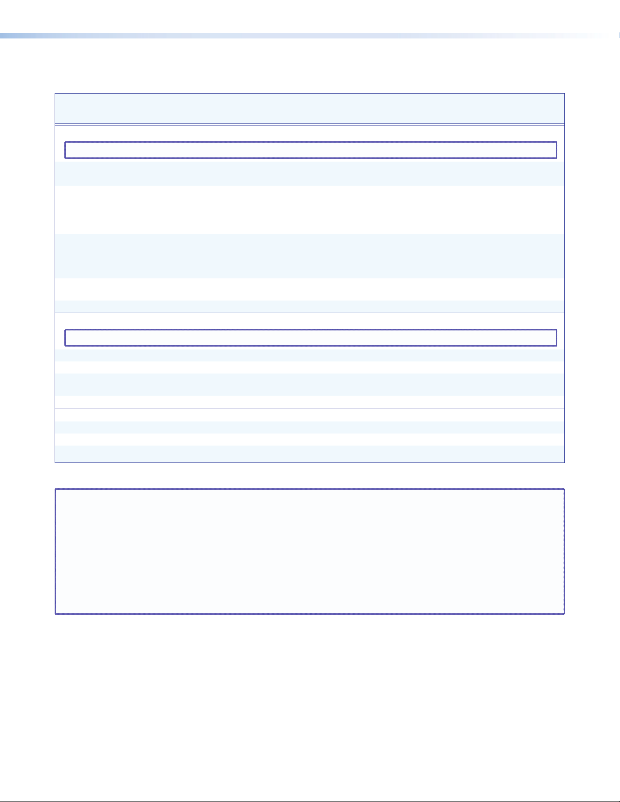
Command/Response Table for SIS Commands (continued)
Command Function
SIS Command
(Host to Unit)
Response
(Unit to Host)
Input skew adjustment
NOTE: For the MTPX Plus 128, these commands are valid for inputs 5 through 12 only.
Set all input skew adjustment values
Example:
Increment one input skew
adjustment value
Example:
Decrement one input skew
adjustment value
Read input skew adjustment values
EX#*X1)*X1)*X1)
E
2*0*0*4Iseq
EX#*X1!
E
EX#*X1!
EX#
+Iseq
2*2+Iseq
}
-Iseq
} X1)*X1)*X1)]
Iseq
}
}
Iseq
}
}
X#*X1)*X1)*X1)]
Iseq
Iseq02*00*00*04
IseqX#*
Iseq02*00*00*05
IseqX#*
X1)*X1)*X1)]
X1)*X1)*X1)]
EDID commands
NOTE: For the MTPX Plus 128, these commands are valid for inputs 1 through 4 only.
Assign EDID data to an input
Assign EDID data to all inputs
Save output #1 EDID data to a user-
defined space
View EDID data assigment
EAX**X1$
EA*X1$
ES*X1$
EA*X*
EDID
}
EDID
}
*EDID
}
EDID
} X1$]
EdidAX**
EdidA0*
X1$]
EdidS
X1$]
Output pre-peaking
Set output pre-peaking on
Set output pre-peaking off
Read output pre-peaking setting
EX1@
EX1@
EX1@
}
*1Opek
}
*0Opek
} X1#]
Opek
Opek
Opek
X1@*1]
X1@*0]
X1$]
]
]
Additional description
Set a specific skew adjustment for the TP
X1)
input.
Set skew settings for input 2 as follows:
Red = 0 ns
Green = 0 ns
Blue = 8 ns (delayed 8 ns).
Increase the
adjustment for input
Increase the blue skew for input 2 by 2 ns
to 10 ns.
Decrease the
for input
For this command, the
be from 31 to 34.
Pre-peak the TP output.
Do not pre-peak the TP output.
values are listed in RGB order.
X1!
plane skew
X#
by 1 step (2 ns).
X1!
plane skew adjustment
X#
by 1 step (2 ns).
X1$
value must
NOTE: X# = TP input number 01 – (maximum number of TP inputs for your model)
X* = Input number 01 – (maximum number of inputs for your model)
X1) = Skew adjustment range 00 – 31 (each step = 2 ns)
X1! = Video plane 0 = red
1 = green
2 = blue
X1@ = Pre-peakable output number MTPX Plus 168 01 – 04
MTPX Plus 128, 816, 1616, 3216 01 – 08
MTPX Plus 1632, 3232 01 – 16
X1# = Pre-peaking 0 = off
1 = on
X1$ = DDC value (EDID) See page 78.
MTPX Plus Series • Programming Guide 82
Page 89

Command/Response Table for SIS Commands (continued)
Command Function
Local video output sync polarity
NOTE: The command structure differs, depending on the size of the matrix. Matrix sizes 816, 168, and 1616 do not need the local
output variable (
Set local output polarity
(matrix size 816, 168, and 1616)
Example:
Set local output polarity
(matrix size 128, 1632, 3216, and
3232)
Example:
Read local output sync settings
(matrix size 816, 168, and 1616)
Read local output sync settings
(matrix size 128, 1632, 3216, and
3232)
X1^
Output skew adjustment
Set all output skew adjustment
values
Example:
Increment one output skew
adjustment value
Decrement one output skew
adjustment value
Example:
Read output skew adjustment values
SIS Command
(Host to Unit)
). Matrix sizes 128, 1632, 3216, and 3232 require the variable.
EX1&
E
0Opol
EX1^*X1&
E
2*0Opol
E
Opol
EX1^
EX@*X1)*X1)*X1)
E
2*0*0*4Oseq
EX@*X1!
EX@*X1!
E
2*2-Oseq
EX@
}
Opol
}
}
Opol
}
} X1&]
} X1&]
Opol
Oseq
}
}
+Oseq
}
-Oseq
}
} X1)*X1)*X1)]
Oseq
Response
(Unit to Host)
Opol
Opol0
Opol
Opol2*0
}
Oseq
Oseq02*0*0*4
OseqX@*
OseqX@*
Oseq02*0*0*3
X1&]
]
X1^*X1&]
]
X@*X1)*X1)*X1)]
]
X1)*X1)*X1)]
X1)*X1)*X1)]
]
Additional description
Set the horizontal and vertical sync
polarity for a local output.
Set the local output to output negative
horizontal and vertical sync.
Set the horizontal and vertical sync
polarity for local output
Set local output 2 to output negative
horizontal and vertical sync.
Set a specific skew adjustment for the
TP output.
order.
Set the output 2 skew settings as
follows:
Red = 0 ns
Green = 0 ns
Blue = 8 ns (delayed 8 ns).
Increase the
adjustment output
Decrease the
adjustment output X@ by 1 step (2 ns).
Decrease the output 2 blue skew by 2 ns
to 6 ns.
X1)
values are listed in RGB
X1!
X1!
X1^
plane skew
X@
by 1 step (2 ns).
plane skew
.
NOTE: X@ = Output number 01 – (maximum number of outputs for your model)
X1) = Skew adjustment range 00 – 31 (each step = 2ns)
X1! = Video plane 0 = red
1 = green
2 = blue
X1^ = Local video output number 1 or 2 (X1^ applies to matrix sizes 128, 1632, 3216, and 3232 only)
X1& = Local output sync polarity 0 = H- / V- (default)
1 = H+ / V 2 = H- / V+
3 = H+ / V+
4 = No sync processing (composite, S-video, YUV)
MTPX Plus Series • Programming Guide 83
Page 90
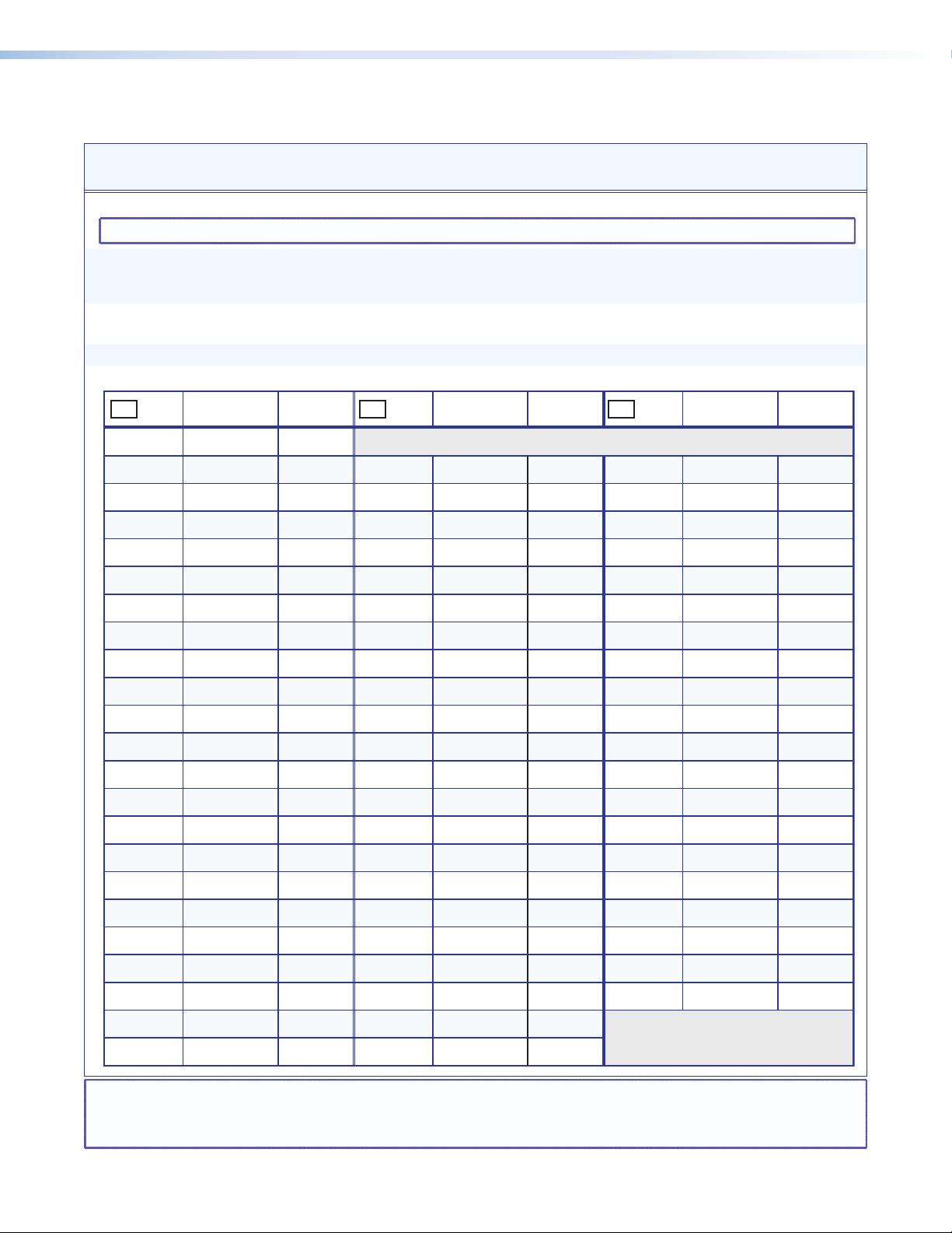
Command/Response Table for SIS Commands (continued)
Command Function
Audio output volume
NOTE: The table below the commands defines the value of each audio volume step.
Set the audio volume to a specific
value
Example:
Increment volume
Example:
Decrement volume
Read output volume
X19 X19 X19
dB of
attenuation
SIS Command
(Host to Unit)
X1**X1(
V Out
1*50v
X1*
+V Out
1+V
X1*
-V Out
X1*
V
Output
volume
Response
(Unit to Host)
X1*
Out01•Vol50
X1*
Out01•Vol51
X1*
X1(]
dB of
attenuation
•Vol
•Vol
•Vol
Output
volume
X1(]
]
X1(]
]
X1(]
76 0%00
01
02
03
04
05
63
62
61
60
59
5.5%
7%
8.5%
10%
11.5%
23
24
25
26
27
41
40
39
38
37
38.5%
40%
41.5%
43%
44.5%
Additional description
Set output 1 volume to 79%.
Increment volume by 1 step.
Decrease volume by 1 step.
valuevaluevalue
45
46
47
48
49
dB of
attenuation
19
18
17
16
15
Output
volume
71.5%
73%
74.5%
76%
77.5%
06
07
08
09
10
58
57
56
55
54
13%
14.5%
16%
17.5%
19%
28
29
30
31
32
36
35
34
33
32
46%
47.5%
49%
50.5%
52%
50
51
52
53
54
14
13
12
11
10
79%
80.5%
82%
83.5%
85%
11
12
13
14
15
16
17
18
19
20
21
22
53
52
51
50
49
48
47
46
45
44
43
42
20.5%
22%
23.5%
25%
26.5%
28%
29.5%
31%
32.5%
34%
35.5%
37%
33
34
35
36
37
38
39
40
41
42
43
44
31
30
29
28
27
26
25
24
23
22
21
20
53.5%
55%
56.5%
58%
59.5%
61%
62.5%
64%
65.5%
67%
68.5%
70%
55
56
57
58
59
60
61
62
63
64
9
8
7
6
5
4
3
2
1
0
86.5%
88%
89.5%
91%
92.5%
94%
95.5%
97%
98.5%
100%
NOTE: X1* = Local audio output number 1 – 2 (MTPX Plus 128)
1 – 4 (other matrix sizes 1616 and smaller)
1 – 8 (matrix sizes 1632 and larger)
X1( = Volume adjustment range 0 – 64 (1 dB/step except for 0-to-1, which is 13 dB)
MTPX Plus Series • Programming Guide 84
Page 91

Command/Response Table for SIS Commands (continued)
Command Function
SIS Command
(Host to Unit)
Response
(Unit to Host)
Audio input gain and attenuation
NOTE: The set gain (G) and set attenuation (g) commands are case sensitive.
Set audio input gain to +dB value
Example:
Set audio input attenuation to -dB
value
Increment gain
Example:
Decrement gain
Example:
Read input gain
Example:
X!*X2)
G InX!•Aud
1*2G
X!*X2@
g InX!•Aud
X!
+G InX!•Aud
5+G
X!
-G InX!•Aud
7-G
X!
G
3G
In1•Aud+02
In5•Aud+03
In7•Aud-09
X2!]
-06
Audio or RS-232 mute commands
Audio or RS-232 mute
Audio or RS-232 unmute
Read audio or RS-232 mute
Global audio or RS-232 mute
Global audio or RS-232 unmute
X@
*1Z AmtX@*1
X@
*0Z AmtX@*0
X@
1*Z
0*Z
Z
X1#]
Amt1
Amt0
Names
]
]
]
X2!]
X2!]
X2!]
X2!]
]
]
]
]
]
Additional description
Set input 1 audio gain to +2 dB.
Increase gain by 1 dB.
Increase audio input 5 level from +2 dB
to +3 dB.
Decrease gain by 1 dB.
Decrease audio input 7 level from -8
dB to -9 dB.
Audio input 3 level is at -6 dB.
Mute output X@ audio or RS-232
(audio off).
Unmute output X@ audio or RS-232
(audio on).
1 = mute on, 0 = mute off.
Mute all audio or RS-232 outputs.
Unmute all audio or RS-232 outputs.
NOTE: The HTML language reserves certain characters for specific functions (see “Special Characters“ on page 95).
Write global preset name
Example:
Read global preset name
Example:
Write room preset name
Example:
Read room preset name
NOTES: • If a preset is unassigned, the
• If a global preset is saved, but not yet named, the default name is Preset
• If a room preset is saved, but not yet named, the default name is Rm
NOTE: X! = Input number 01 – (maximum number of inputs for your model)
EX2#,X2$NG}
E
1,Security 1NG
}
X2#,X2$]
Nmg
Nmg01,Security 1
Name global preset 1 “Security 1”.
]
EX2#NG} X2$]
E
}
2NG
EX2%*X2#,X2$NP}
E
1*3,Podium_DVDNP
EX2%,X2#NP}
X2$
displays [unassigned].
Security 2
Nmp
}
Nmp01*3
X2$]
X2%*X2#,X2$]
]
,Podium_DVD
X2#
.
X2%
X2#
Prst
.
Name room 1, preset 3 “Podium_DVD”.
]
X@ = Output number 01 – (maximum number of outputs for your model)
X* = Input number 01 – (maximum number of inputs for your model)
X1# = Mute 0 = off 1 = on
X2) = Audio gain 0 – 24 (1 dB/step)
X2! = Numeric dB value –18 to +24 (45 steps of gain or attenuation) (Default = 0 dB)
X2@ = Audio attenuation 1 – 18 (1 dB/step)
X2# = Global or room preset # 01 - 32, 10 maximum for a room preset
X2$ = Name 11 characters for room preset names
X2% = Room # (for room presets) 10 max. (each can have up to 10 presets (X2#s) assigned)
MTPX Plus Series • Programming Guide 85
Page 92
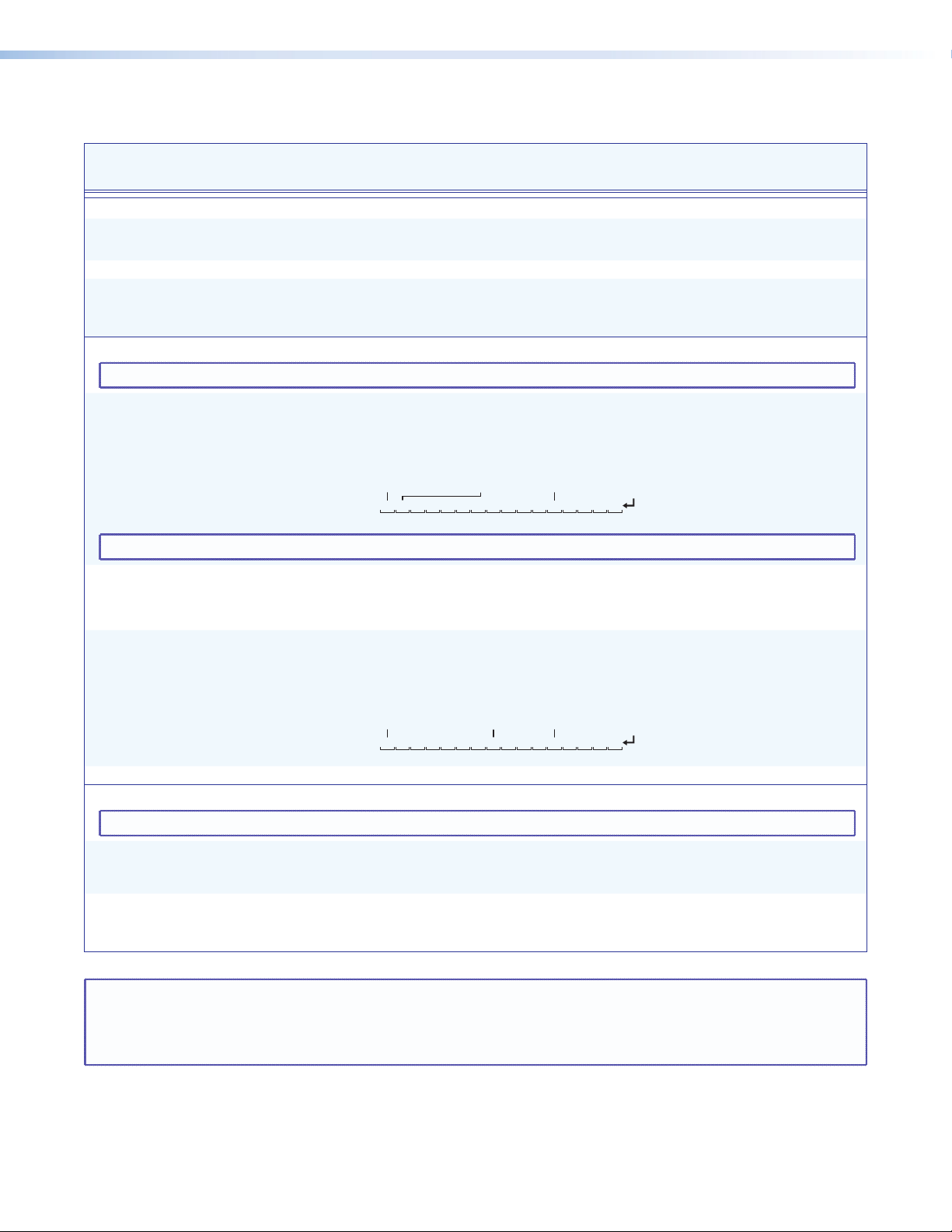
Command/Response Table for SIS Commands (continued)
Input 1 in group 1
Input 8 not grouped Input 12 in group 4
Command Function
SIS Command
(Host to Unit)
Response
(Unit to Host)
Names (continued)
Write input name
Example:
Read input name
Write output name
Example:
Read output name
EX*,X2$NI}
E
1,Podium camNI
}
Nmi
Nmi01,Podium cam
EX*NI} X2$]
EX@,X2$NO}
E
1,Main PJ1NO
}
Nmo
Nmo01,Main PJ1
EX@NO} X2$]
X*,X2$]
X@,X2$]
I/O Grouping
NOTE: The group that is assigned in each of the following I/O grouping commands (
2
Write input grouping
Example: MTPX Plus 168
NOTE: You must enter an
Write output grouping
Read input grouping
Example: MTPX Plus 1616
EX2^1X2^
E4013300004440443I
Input 1 in group 4
X2^
value for each input in your matrix size, such as 32 inputs for an MTPX Plus 3216.
X2^1X2^
E
} X2^1X2^2X2^
EI
}
EI
n
X2^
}
...
I
Input 2 not grouped Input 12 in group 4
GriResponse #s = group:
401330000444
01 Input:
02 03 04 05 06 07 08 09 10 11 12
2
n
X2^
}
...
O
Gri
}
Gri4013300004440443] (see below)
Gro
11113300004440444] (see below)
X2^1X2^2X2^
X2^1X2^2X2^
Additional description
Name input 1 “Podium cam”.
]
]
X2^
) must be 1, 2, 3, 4, or 0 (not grouped).
3
X2^n]
...
0443
13 14 15 16
3
X2^n]
...
3
X2^n]
...
Name output 1 “Main PJ1”.
n = the maximum number of inputs.
X2^
Each
entry is the group
number assigned to an input
position, starting from input 1.
Input 1 - Group 4, Input 2 - Group 0
(not grouped), ... Input 16 - Group 3.
n = the maximum number of outputs.
X2^
Each
entry is the group number
assigned to an output position, starting
from output 2.
n = the maximum number of inputs.
X2^
Each
entry is the group number
assigned to an output position, starting
from input 1.
Read output grouping
Save, recall, and directly write global presets
NOTE: If you try to recall a preset that is not saved, the matrix switcher responds with the error code E11.
Save current configuration as a
global preset
Recall a global preset
NOTE: X@ = Output number 01 – (maximum number of outputs for your model)
Example:
Example:
X* = Input number 01 – (maximum number of inputs for your model)
X2# = Global or room preset # 01 - 32, 10 maximum for a room preset
X2% = Room # (for room presets) 10 max. (each can have up to 10 presets (X2#s) assigned)
X2^ = Group # 1 through 4 groups (0 = no group)
Response = group:
} X2^1X2^2X2^
EO
X2#
, Spr
8,
X2#
. Rpr
5.
111330000444
01Input:
02 03 04 05 06 07 08 09 10 11 12
X2#]
Spr08
X2#]
Rpr05
]
]
0444
13 14 15 16
3
X2^n]
...
n = the maximum number of outputs.
Command character is a comma.
Save current ties as preset 8.
Command character is a period.
Recall preset 5, which becomes the
current configuration.
MTPX Plus Series • Programming Guide 86
Page 93

Command/Response Table for SIS Commands (continued)
Command Function
SIS Command
(Host to Unit)
Save, recall, and directly write global presets (continued)
Direct write process —
NOTE: The direct write of a global preset should always be preceded by a clear global preset ties command of that same preset number,
If you do not clear the ties in a global preset number before you directly write a global preset to that number, ties that are part of
Clear global preset ties
Directly write a global preset
Write room outputs
NOTES: • A room can contain a maximum of 16 outputs (X@s).
• An output can belong to only one room.
• The maximum number of rooms (
• If no room name is assigned, the default name is “Room #
Read room outputs
Recall room preset
Clear room preset ties
Directly write a room preset
as shown below. In a directly-written preset, the input for each output position (or no tied input) remains unchanged unless
overwritten or cleared.
the previous version of the specified preset with the same number can unexpectedly become part of the newly-created preset.
E+X2#
P0*!
}
E+X2#PX!*X@!X!*X@%X!*X@
Example:
Example:
E
+27P0*!
Esc
+27P12*5!10*09%3*2$3*8&
EX2%,X@
E
8,3,04,5,6MR
X2%
}
1
2
X@
,
s) is 10.
, ...
n
X@
MR]Mpr
}
EX2%MR} X2#,X@
E
Example:
}
3MR
X2%*X2#
.
E+X2%*X2#
P0*!
]
E+X2%*X2#PX!*X@!X!*X@%X!*X@
Example:
Esc
+7*3P12*7&11*5$4*5%6*6!
Lock (executive) modes
Response
(Unit to Host)
X2#]
Spr
X2#]
]
]
1
X2%,X@
.”
1
X@
,
X2%
•Rpr
X2%
•Spr
$ ... X!*X@&
X2%
•Spr
}
X@
,
2
, ...
X2#]
X2#]
X2#]
2
]
, ...
X@n]
}
X@n]
$ ... X!*X@&
Spr
Spr27
Spr27
X2%
Mpr8,03,04,05,06
Class 1,01,02,08,09
Rmm
Rmm
Rmm
Rmm07•Spr03
Additional description
Clear all ties in preset
The tie all (!), tie RGB (&),
tie video (%), and tie audio ($)
commands are all valid.
Clear all ties in preset 27.
Brackets are shown to separate ties for
clarity only. Create global preset 27,
which ties video and audio input 12 to
output 5, video input 10 to output 9,
audio input 3 to output 2, and video
input 3 to output 8.
X2#
See notes.
]
Outputs 3, 4, 5, and 6 are
assigned to room 8.
]
Outputs 1, 2, 8, and 9 are assigned to
room 3, which named “Class 1”.
Command character is a period.
Clear all ties in room
Enter as many ties as are valid for this
model. Tie all (!), tie RGB (&), tie video
(%), and tie audio ($) commands are
all valid.
Brackets are shown to separate ties for
clarity only. Create preset 3 for room 7,
which ties audio input 12 to output 7,
video input 11 to output 5, RGB input
4 to output 5, and video and audio
input 6 to output 6.
X2#
preset
.
X2#
.
NOTE: See “Setting the Front Panel Locks (Executive Modes)” in the “Operation” section for more information on the Lock modes.
Lock all front panel functions
Lock advanced front panel functions
Unlock all front panel functions
View lock status
NOTE: X! = Input number 01 – (maximum number of inputs for your model)
1X
2X
0X
X
Exe1
Exe2
Exe0
X1#]
]
]
]
Enable Lock mode 1.
Enable Lock mode 2.
Enable Lock mode 0.
X@ = Output number 01 – (maximum number of outputs for your model)
X1# = Lock mode 0 = mode 0 1 = mode 1 2 = mode 2
X2# = Global or room preset # 01 - 32, 10 maximum for a room preset
X2% = Room # (for room presets) 10 max. (each can have up to 10 presets (X2#s) assigned)
MTPX Plus Series • Programming Guide 87
Page 94

Command/Response Table for SIS Commands (continued)
Command Function
SIS Command
(Host to Unit)
Response
(Unit to Host)
Resets
Reset all input level and peaking
adjustments
Reset all input and output skew
adjustments
Reset global presets and names
Reset one global preset
Reset audio input levels
Reset audio output levels
Reset all mutes
Reset room map (outputs)
Reset individual room
Reset all room presets and names
Reset individual room preset and name
Reset whole switcher
Absolute reset
EZT}
EZK}
EZG}
EX2#ZG}
EZA}
EZV}
EZZ}
EZR}
EX2%ZR}
EZP}
EX2%*X2#ZP}
E
E
ZXXX
ZQQQ
}
}
Zpt
Zpk
Zpg
Zpg
Zpa
Zpv
Zpz
Zpr
Zpr
Zpp
Zpp
Zpx
Zpq
View ties, gain, volume, mutes, presets, and DIP switch status
Read RGB
Example:
Read video output tie
Example:
Read audio output tie
Example:
View output volume
Example:
View input gain
Example:
(video) output tie
X@
5&
X@
7%
X@
3$
X1*
7V
X*
4G
&
%
$
V
G
X!]
12
X!]
02
X!]
06
X1(]
55
X2!]
-02
]
]
]
X2#]
]
]
]
]
X2%]
]
X2%*X2#]
]
]
]
]
]
]
]
Additional description
Clear all level and peaking adjustments
to their default (0) values.
Clear all input and output skew values
to 0 ns.
Clear all global presets and their names.
X2%
X2#
.
.
Clear global preset
Reset all audio input levels (gain and
attenuation) to 0 dB.
Reset all audio output levels (volume)
to 100% (no attenuation).
Reset all audio or RS-232 outputs to
unmuted.
Clear all room definitions.
Delete room
Clear an individual room preset and name.
Clear an individual room preset and name.
Clear all ties and presets, reset all audio
gains to 0 dB, and reset volume to 100%.
Similar to Reset whole switcher, plus
clear the IP address to 192.168.254.254
and subnet mask to 255.255.000.000.
RGB input X! is tied to output X@.
Input 12 RGB is tied to output 5.
RGB input X! is tied to output X@.
Input 2 video is tied to output 7.
Audio input X! is tied to output X@.
Input 6 audio is tied to output 3.
Volume for output 7 is 55%.
Audio input 3 level is -2 dB.
NOTE: X! = Input number 00 – (maximum number of inputs for your model)
X@ = Output number 01 – (maximum number of outputs for your model)
X* = Input number 01 – (maximum number of inputs for your model)
X1* = Local audio output number 1 – 2 (MTPX Plus 128)
1 – 4 (matrix sizes 1616 and smaller)
1 – 8 (matrix sizes 1632 and larger)
X1( = Volume adjustment range 0 – 64 (1 dB/step except for 0-to-1, which is 22 dB)
X2! = Numeric dB value –18 to +24 (45 steps of gain or attenuation) (Default = 0 dB)
X2# = Global or room preset # 01 - 32 (global) or 01-10 (room)
X2% = Room # (for room presets) 10 max. (each can have up to 10 presets (X2#s) assigned
MTPX Plus Series • Programming Guide 88
Page 95
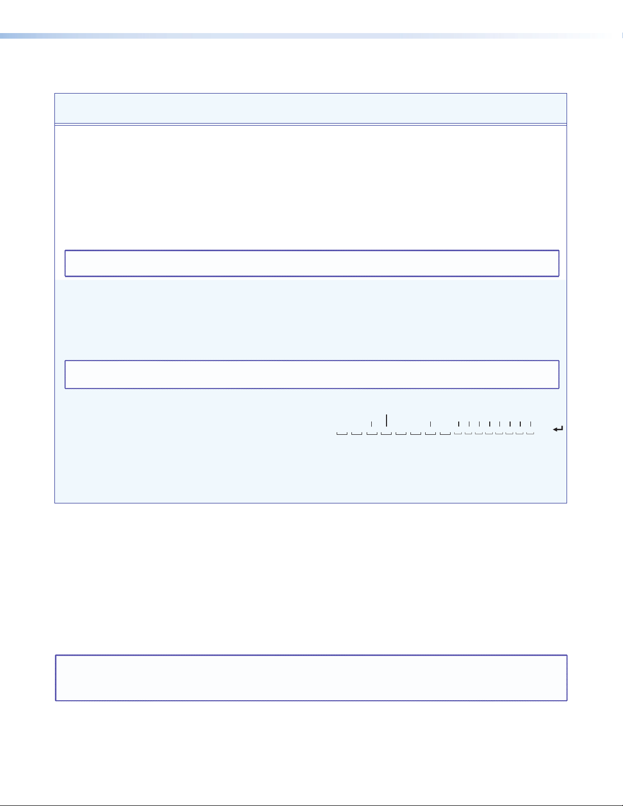
Command/Response Table for SIS Commands (continued)
input 8 tied to output 4
Command Function
SIS Command
(Host to Unit)
Response
(Unit to Host)
Additional description
View ties, gain, volume, mutes, presets, and DIP switch status (continued)
2
n+1
...
•
X!
X2&
n+1
n
Mut
•
X!
n+2
]
X2&
Each
an output: left = output 1,
right = output n. n = the highest
output number for this model.
response is the mute status of
]
Output 1 is unmuted, output 2 video
is muted, output 3 video and audio are
muted, and output 4 audio is muted.
Outputs 5 through 8 are not present
on this switcher.
n+15
•...•
X!
]
•Vid
Show the video configuration for
X2#
preset
16 sequential outputs, starting from
output
. Show the input tied to
X@
.
]
View output mutes
Example (MTPX Plus 3216):
NOTE: The “Mut” portion of the response appears only when the switcher is in Verbose mode 1 or 3 (see the Set verbose mode SIS
View video global preset
configuration
NOTES: • The starting output number (X@) should always be “1” for matrix sizes of 16 outputs or smaller.
•
command on page 95).
Command description:
Response description:
EX2#*X@
Example (MTPX Plus 168):
*1VC} where
EVM} X2&1X2&
EVM}
EX2#*X@
preset #*starting output # (StO#)*1(=video)VC
input # (I#) tied to StO#•I# tied to StO#+1•I# tied to StO#+2• ... •I# tied to StO#+15•Vid
X2#
= 0 returns the current video configuration.
E
3*1*1VC
} X!
*1VC
}
Mut0220200002202000
n
X!
•
input 12 tied to output 3
Response = tied input:
Each position shown in the response is an output: left = starting output (1), right = starting output
+15 (16). (Outputs 9 through 16 are not present on the MTPX Plus 168.) The number in each
NOTE: X! = Input number 00 – (maximum number of inputs for your model)
position is the input tied to that output.
In this example, preset 3, video input 8 is tied to outputs 1, 2, 4, and 5; input 12 is tied to output 3;
and input 11 is tied to output 6. No inputs are tied to outputs 7 and 8.
08•08•12•08•08•11•00•00•
2345678
1Output:
no tied input
outputs do not exist
•--•--•--•--•--•--•--•--•
13 14 15 1609 10 11 12
•Vid
X@ = Output number 01 – (maximum number of outputs for your model)
X2# = Global or room preset # 01 - 32 (global) or 01-10 (room)
X2& = Audio or RS-232 mute: 0 = no mutes 2 = audio or RS-232 mute
MTPX Plus Series • Programming Guide 89
Page 96

Command/Response Table for SIS Commands (continued)
Command Function
SIS Command
(Host to Unit)
Response
(Unit to Host)
Additional description
View ties, gain, volume, mutes, presets, and DIP switch status (continued)
n
n+1
n+1
View audio global preset
EX2#*X@
} X!
*2VC
X!
•
•
X!
n+2
X!
•
configuration
Command description:
Response description:
preset #*starting output # (StO#)*2(=audio)VC
input # (I#) tied to StO#•I# tied to StO#+1•I# tied to StO#+2• ... •I# tied to StO#15•Aud
NOTES: • The starting output number (X@) should always be “1” for matrix sizes of 16 outputs or smaller.
•
EX2#*X@
*2VC} where
Example: (MTPX Plus 1632)
X2#
= 0 returns the current audio configuration.
E
15*17*2VC
Response = tied input:
}
input 1 tied to output 19
01•01•01•01•02•12•12•00•00•00•00•00•01•08•15•16•Aud
18 19 20 21 22 23 24
17Output:
Each position shown in the response is an output: left = starting output (17), right =
starting output +15 (32). The number in each position is the input tied to that output.
In this example, preset 15, audio input 1 is tied to outputs 17, 18, 19, 20, and 29; input 2 is tied
to output 21; input 12 is tied to outputs 22 and 23; input 8 is tied to output 30; input 15 is tied to
output 31; and input 16 is tied to output 32. No input is tied to output 24, 25, 26, 27, and 28.
n
n+1
n+1
View video room preset
EX2%*X2#
*1*1VC
} X!
X!
•
•
X!
n+2
X!
•
configuration
Command description:
Response description:
room #*room preset #*starting output # (StO#)*1(=video)VC
input # (I#) tied to StO#•I# tied to StO#+1•I# tied to StO#+2• ... •I# tied to StO#+15•Vid
n+15
X!
•...•
Show the audio configuration for preset
X2#
outputs, starting from output
no tied input
25 26 27 28 29 30 31 32
n+15
X!
•...•
Show the video configuration for room
X2%
up to 16 outputs assigned to room
]
•Aud
. Show the input tied to 16 sequential
X@
.
]
]
•Vid
X2#
, preset
. Show the input tied to
X2%
]
.
NOTE: The starting output number (X@) should always be “1” for matrix sizes of 16 outputs or smaller.
View audio room preset
configuration
Command description:
Response description:
NOTE: The starting output number (X@) should always be “1” for matrix sizes of 16 outputs or smaller.
View Input Select DIP switch
positions and level/peaking status
NOTE: This command is invalid for the MTPX Plus 128 only.
NOTE: X! = Input number 00 – (maximum number of inputs for your model)
X@ = Output number 01 – (maximum number of outputs for your model)
X( = Threshold 0 = outside of threshold 1 = within threshold
X2# = Global or room preset # 01 - 32 (global) or 01-10 (room)
X2% = Room # (for room presets) 10 max. (each can have up to 10 presets (X2#s) assigned
X2* = Local input select DIP switch status 0 = RJ-45 position 1 = local input position
EX2%*X2#
*1*2VC
} X!
X!
n+2
X!
•
X!
•
•
•...•
X!
n+15
•Aud
]
n
n+1
n+1
Show audio configuration for room
X2#
preset
. Show the input tied to up to
16 outputs assigned to room
room #*room preset #*starting output # (StO#)*2(=audio)VC
input # (I#) tied to StO#•I# tied to StO#+1•I# tied to StO#+2• ... •I# tied to StO#+15•Aud
E
Stat
}
X2*
1
X2*2X2*
n
3
X2*
X(]
...
*
X2*
Each
is the position for that rear panel
Input Select DIP switch from 1 to n. n = 3
for matrix sizes up to 1616, n = 6 for
matrix sizes of 1632 and larger.
indicates whether the input level/peaking
is within the pre-determined threshold
for the input tied to output 1 only.
]
X2%
X(
X2%
,
.
MTPX Plus Series • Programming Guide 90
Page 97

Command/Response Table for SIS Commands (continued)
Command Function
SIS Command
(Host to Unit)
Response
(Unit to Host)
Additional description
View ties, gain, volume, mutes, presets, and DIP switch status (continued)
NOTE: The response to the View File Directory command differs, depending on whether the command is sent via an RS-232/RS-422 or
View le directory
RS-232/RS-422 port and Telnet
View le directory
Web browser
Erase user-supplied Web pages/les
Telnet connection or sent via a Web browser connection.
EDF}
EDF}
E
filenameEF
}
filename1,date/time,length]
filename2,date/time,length]
filename3,date/time,length]
filenamen,date/time,length]
# of Bytes•Left]
•
•
Var file = new array ();
File [1] = ‘filename1,date1,filesize1‘;
File [2] = ‘filename2,date2,filesize2‘;
File [3] = ‘filename3,date3,filesize3‘;
File [n] = ‘filenamen,daten,filesizen‘;
File [n+1] = # of Bytes•Left
Delfilename
•
•
]
•
•
]
List user-supplied files.
List user-supplied files.
•
•
Information requests
Information request
Request part number
I
N
X2(XX3)•AX2(XX3)]
V
X3!]
V (video) matrix size•
A (audio) matrix size
See “Part Numbers and
Accessories” in the “Reference
Information” section.
NOTE: There are up to three separate sets of Extron firmware on which the switcher can report: the controller firmware, which is the
Query controller rmware version
Query controller rmware version
(verbose)
Ethernet protocol
NOTE: X2( = Number of inputs 8, 12, 16, or 32
overall control firmware; the Ethernet protocol firmware, which handles the Ethernet interface; and the latest optional Extron
firmware update, which is available at www.extron.com.
Example:
Response description: Ethernet protocol rmware version-controller rmware version-updated rmware version]
Example:
1.23-1.00(1.06-16x16 Series -Tue, 04 Dec 2007 00:00:00 GMT)-1.00*(1.06-16x16 Series -Thu, 27 Dec 2006 16:39:21 GMT)
firmware
X3) = Number of outputs 8, 16, or 32
X3! = Part number 60-nnn-nn
X3@ = Firmware version number to second decimal place (x.xx)
X3# = Verbose firmware version-description-upload date/time
Q
Q
0Q
0q
Description
MTPX firmware version
X3@]
]
1.23
X3@-X3#-X3#]
* indicates the version running Upload date and time
The factory-installed controller firmware
version is 1.23 (sample value only).
Provide a detailed status of the MTPX
Plus controller firmware and any
firmware upgrade. The firmware that
is running is marked by an asterisk (*).
A caret (^) indicates that the rmware
has a bad checksum or an invalid load.
?.?? indicates that firmware is not
loaded.
Updated firmware version
MTPX Plus Series • Programming Guide 91
Page 98

Command Function
+12V power system at 11.52V
SIS Command
(Host to Unit)
Response
(Unit to Host)
Information requests (continued)
Request system status
MTPX Plus 128:
Other matrix sizes 1616 and smaller:
Matrix sizes 1632 and larger:
Response description (MTPX Plus 128):
Response description (other matrix sizes 1616 and smaller):
Response description (matrix sizes 1632 and larger):
+3.3V•+5V•-5V•+12V•-12V•+2.5V•-2.5V•temperature (degrees Fahrenheit)•Fan 1 speed•Fan 2•Fan 3
NOTE: Fans are numbered 1, 2, 3, from rear to front.
Example (MTPX Plus 128):
NOTE: X3$ = Voltage Positive or negative voltage and magnitude
X3% = Temperature Degrees Fahrenheit
X3^ = Fan speed RPM
S See below
X3$•X3$•X3$•X3$•X3$•X3%•X3^•X3^•X3^]
X3$•X3$•X3$•X3$•X3$•X3%•X3^•X3^]
X3$•X3$•X3$•X3$•X3$•X3$•X3$•X3%•X3^•X3^•X3^]
+3.3V•+5V•-5V•+12V•-12V•temperature (degrees Fahrenheit)•Fan 1 speed•Fan 2•Fan 3
+3.3V•+5V•-5V•+12V•-12V•temperature (degrees Fahrenheit)•Fan 1 speed•Fan 2
S
+3.28•+4.98•-5.01•+11.52•-12.35•+086.80•03590•03668•03668
Additional description
]
]
]
Fan 1 (rear) rotating at 3590 RPM+3.3V power system at 3.28V
MTPX Plus Series • Programming Guide 92
Page 99

Symbol definitions
X4) = Matrix name (Up to 240 alphanumeric characters)
NOTE: The HTML language reserves certain characters for specific functions (see “Special Characters“ on page 95).
X4! = Default name MTPX- + last 3 pairs of MAC address
X4@ = Time and date (for set) In the format: MM/DD/YY•HH:MM:SS where:
MM = month: 01 (January) through 12 (December)
DD = 01 through 31
YY = 00 through 99
HH = 00 through 23
MM = 00 through 59
SS = 00 through 59
X4# = Time and date (for read) In the format: Day,•DD•Mmm•YYYY•HH:MM:SS where:
Day of the week: Mon through Sun
DD = 01 through 31
Mmm = month: Jan through Dec
YYYY = 2000 through 2099
HH = 00 through 23
MM = 00 through 59
SS = 00 through 59
X4$ = GMT offset –12.0 through +14.0. Hours and minutes removed from GMT
X4% = Daylight Savings Time 0 = Daylight Savings Time off/ignore
1 = Daylight Savings Time on (northern hemisphere)
2 = Daylight Savings Time on (Europe)
3 = Daylight Savings Time on (Brazil)
X4^ = IP address ###.###.###.###
X4& = Hardware (MAC) address ##-##-##-##-##-##
X4* = Number of open connections 000 - 200
X4( = Password Up to 12 alphanumeric characters
NOTE: The HTML language reserves certain characters for specific functions (see “Special Characters“ on page 95).
X5) = Domain name Standard domain name rules apply (for example: xxx.com)
NOTE: The HTML language reserves certain characters for specific functions (see “Special Characters“ on page 95). The @ character is
acceptable only as the lead-in to the domain name (such as @extron.com).
X5! = E-mail account 65 - 72. 65 = e-mail recipient 1, 66 = 2, 67 = 3, ... 72 = recipient #8
X5@ = E-mail address Typical e-mail address format (for example: nnnn@xxx.com)
X5# = Notify when? 0 = no response 3 = both 1 & 2
1 = fail/missing 4 = suspend
2 = xed/restored
X5$ = Notication selections 00 = both fans, 01 (fan 1), or 02 (fan 2)
X5% = Notify status (for read) 17-digit number. For each digit: 0 = do not notify, 1 = notify
X5^ = DHCP 0 = off, 1 = on
X5& = Port # 00 through 99 (00 = all ports)
X5* = Baud rate 9600, 19200, 38400, 115200
X5( = Parity odd, even, none, mark, space (only the first letter required)
X6) = Data bits 7, 8
X6! = Stop bits 1, 2
X6@ = Port type 0 = RS-232
1 = RS-422
2 = RS-485
MTPX Plus Series • Programming Guide 93
Page 100

X6# = Verbose mode 0 = clear/none (default for Telnet connection)
1 = verbose mode (default for RS-232/RS-422 connection)
2 = tagged responses for queries
3 = verbose mode and tagged for queries
NOTE: If tagged responses is enabled (modes 2 and 3), all read commands return the constant string and the value as the set command
does (for example, the read matrix name command ECN}, returns Ipn•X4)]).
X6$ = Flow control hardware, software, none (only the first letter required)
X6% = Data pacing (in ms between bytes) 0000 (default) - 1000
X6^ = Time (in 10 ms increments) to wait for characters 10 (= 100 ms, default) - 32767
X6& = Time (in 10 ms increments) to wait between characters 2 (= 20 ms, default) - 32767
X6* = Port timeout interval (in 10-sec. increments) 1 (= 10 seconds) - 65000 (default is 30 = 300 seconds = 5 minutes)
Command/Response Table for IP-specific SIS Commands
Command Function
IP setup commands
Set matrix name
Read matrix name (location)
Reset matrix name to factory default
Set time and date
Read time and date
Set GMT offset
Example:
Read GMT offset
Set Daylight Savings Time
Read Daylight Savings Time
Set IP address
Read IP address
Read hardware address
Read # of open connections
Set subnet mask
Read subnet mask
Set gateway IP address
Read gateway IP address
Set administrator password
Read administrator password
Reset (clear) administrator password
Set user password
Read user password
Reset (clear) user password
Set mail server, domainname
Read mail server, domainname
Set e-mail recipient
Example:
Read e-mail recipient
SIS Command
(Host to Unit)
EX4)CN}
Response
(Unit to Host)
Ipn•
ECN} X4)]
E
}
•CN
X4@CT}
E
Ipn•
Ipt
ECT} X4#]
EX4$CZ}
E
8.3CZ
}
Ipz
Ipz+08:30
ECZ} X4$]
EX4%CX} X4%]
ECX} X4%]
EX4^CI}
Ipi
ECI} X4^]
ECH} X4&]
ECC} X4*]
EX4^CS}
Ips
ECS} X4^]
EX4^CG}
Ipg
ECG} X4^]
EX4(CA}
Ipa•
ECA} X4(]
E
}
•CA
EX4(CU}
Ipa•
Ipu•
ECU} X4(]
E
}
•CU
EX4^,X5),X4(CM}
ECM}
EX5!,X5@CR}
E
72,Jsmith@folklore.netCR
EX5!CR}
Ipu•
Ipm
X4^
,
Ipr
Ipr72,Jsmith@folklore.net,
X5@
,
X4)]
X4)]
X4@]
X4$]
]
X4^]
X4^]
X4^]
X4(]
]
X4(]
]
X4^,X5),X4(]
X5),X4(]
X5!,X5@,]
}
]
Additional description
In the command, the divider between
hours and minutes can be either a
colon or a period. In the response, the
divider is a colon.
8.3 = 8:30
Reads MAC address.
This command sets the recipient. To
receive e-mail notifications, you must then
set the events that the switcher reports,
using one or more separate Set e-mail
events (EM) commands (see next page).
]
MTPX Plus Series • Programming Guide 94
 Loading...