

Page 1
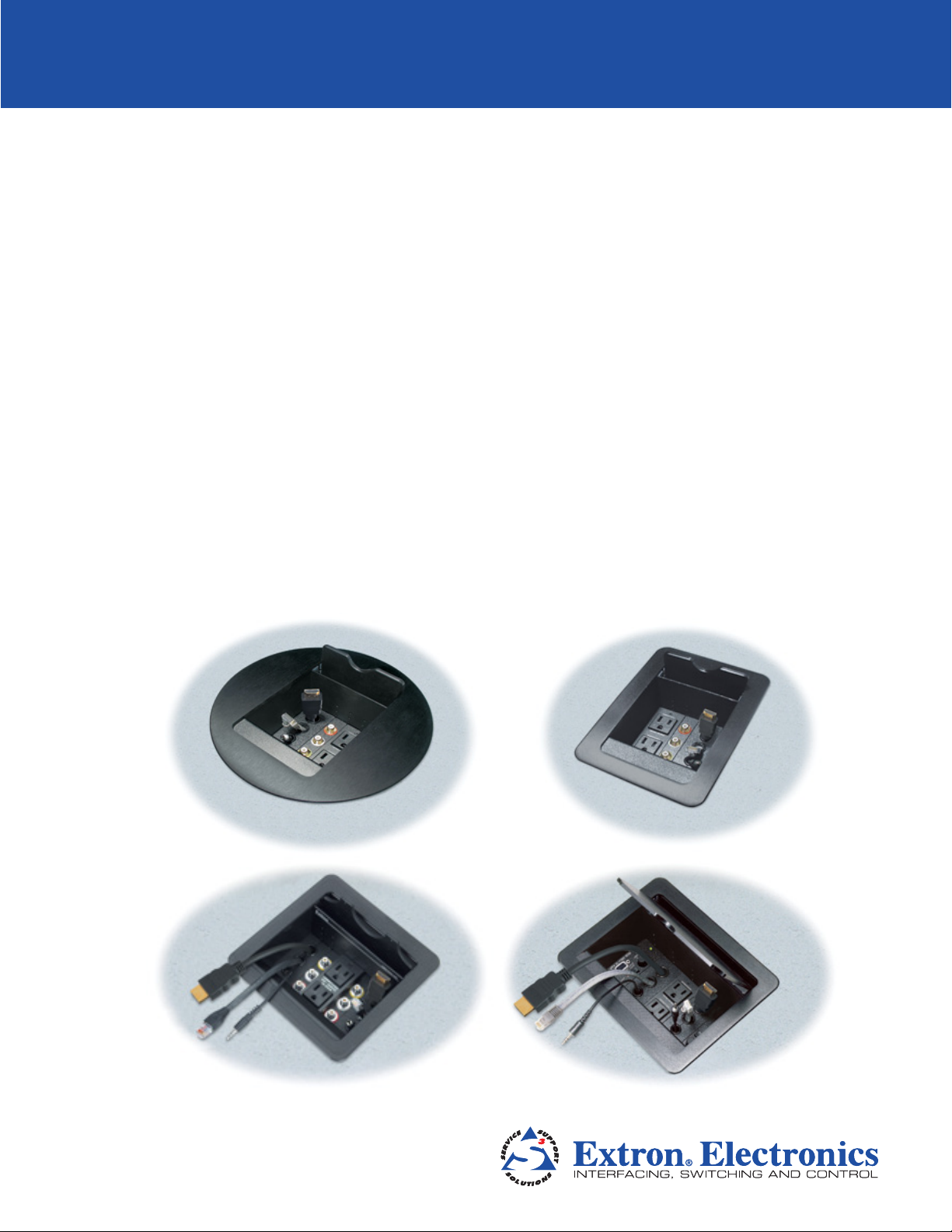
Cable Cubby® 300C
Cable Cubby® 300S
Cable Cubby® 600
Cable Cubby® 800
Cable Access Enclosures
User Guide
Architectural Connectivity
68-1558-01 Rev. A
10 12
Page 2
Safety Instructions
Safety Instructions • English
WARNING: This symbol, , when used on the product, is intended
to alert the user of the presence of uninsulated dangerous voltage
within the product’s enclosure that may present a risk of electric
shock.
ATTENTION: This symbol, , when used on the product, is intended
to alert the user of important operating and maintenance (servicing)
instructions in the literature provided with the equipment.
For information on safety guidelines, regulatory compliances, EMI/EMF
compatibility, accessibility, and related topics, see the Extron Safety and
Regulatory Compliance Guide, part number 68-290-01, on the Extron
website, www.extron.com.
Instructions de sécurité • Français
AVERTISSEMENT: Ce pictogramme, , lorsqu’il est utilisé sur le
produit, signale à l’utilisateur la présence à l’intérieur du boîtier
du produit d’une tension électrique dangereuse susceptible de
provoquer un choc électrique.
ATTENTION: Ce pictogramme, , lorsqu’il est utilisé sur le produit,
signale à l’utilisateur des instructions d’utilisation ou de maintenance
importantes qui se trouvent dans la documentation fournie avec le
matériel.
Pour en savoir plus sur les règles de sécurité, la conformité à la
réglementation, la compatibilité EMI/EMF, l’accessibilité, et autres sujets
connexes, lisez les informations de sécurité et de conformité Extron, réf.
68-290-01, sur le site Extron, www.extron.fr.
Sicherheitsanweisungen • Deutsch
WARNUNG: Dieses Symbol auf dem Produkt soll den Benutzer
darauf aufmerksam machen, dass im Inneren des Gehäuses dieses
Produktes gefährliche Spannungen herrschen, die nicht isoliert sind
und die einen elektrischen Schlag verursachen können.
VORSICHT: Dieses Symbol auf dem Produkt soll dem Benutzer in
der im Lieferumfang enthaltenen Dokumentation besonders wichtige
Hinweise zur Bedienung und Wartung (Instandhaltung) geben.
Weitere Informationen über die Sicherheitsrichtlinien, Produkthandhabung,
EMI/EMF-Kompatibilität, Zugänglichkeit und verwandte Themen finden Sie
in den Extron-Richtlinien für Sicherheit und Handhabung (Artikelnummer
68-290-01) auf der Extron-Website, www.extron.de.
Chinese Simplified(简体中文)
警告: 产品上的这个标志意在警告用户该产品机壳内有暴露的危险
电 压 ,有 触 电 危 险 。
注意: 产品上的这个标志意在提示用户设备随附的用户手册中有
重要的操作和维护(维修)说明。
关于我们产品的安全指南、遵循的规范、EMI/EMF 的兼容性、无障碍
使用的特性等相关内容,敬请访问 Extron 网站 www.extron.com,参见 Extron
安全规范指南,产品编号 68-290-01。
Chinese Traditional(繁體中文)
警告: 若產品上使用此符號,是為了提醒使用者,產品機殼內存在著
可能會導致觸電之風險的未絕緣危險電壓。
注意 若產品上使用此符號,是為了提醒使用者。
有關安全性指導方針、法規遵守、EMI/EMF 相容性、存取範圍和相關主題的詳細
資訊,請瀏覽 Extron 網站:www.extron.com,然後參閱《Extron 安全性與法
規遵守手冊》,準則編號 68-290-01。
Japanese
警告: この記 号 が製品上に表示されている場合は、筐体内に絶縁されて
いない高電圧が流れ、感電の危険があることを示しています。
注意: この記号 が製品上に表示されている場合は、本機 の取扱説明 書に記載されて
いる重要な操 作と保 守( 整 備) の指 示につ いてユーザーの 注意を喚 起するもので す。
安全上のご注意、法令遵守、EMI/EMF適合性、その他の関連項目に
つ い て は 、エ ク スト ロ ン の ウェ ブ サ イト www.extron.comより
『Extron Safety and Regulatory Compliance Guide』 (P/N 68-290-01) をご覧く
ださい。
Korean
Instrucciones de seguridad • Español
ADVERTENCIA: Este símbolo, , cuando se utiliza en el producto,
avisa al usuario de la presencia de voltaje peligroso sin aislar dentro
del producto, lo que puede representar un riesgo de descarga
eléctrica.
ATENCIÓN: Este símbolo, , cuando se utiliza en el producto, avisa
al usuario de la presencia de importantes instrucciones de uso y
mantenimiento recogidas en la documentación proporcionada con
el equipo.
Para obtener información sobre directrices de seguridad, cumplimiento
de normativas, compatibilidad electromagnética, accesibilidad y temas
relacionados, consulte la Guía de cumplimiento de normativas y seguridad
de Extron, referencia 68-290-01, en el sitio Web de Extron,
www.extron.es.
경고: 이 기호 , 가 제품에 사용될 경우, 제품의 인클로저 내에 있는
접지되지 않은 위험한 전류로 인해 사용자가 감전될 위험이 있음을
경고합니다.
주의: 이 기호 , 가 제품에 사용될 경우, 장비와 함께 제공된 책자에 나와
있는 주요 운영 및 유지보수(정비) 지침을 경고합니다.
안전 가이드라인, 규제 준수, EMI/EMF 호환성, 접근성, 그리고 관련
항목에 대한 자세한 내용은 Extron 웹 사이트(www.extron.com)의
Extron 안전 및 규제 준수 안내서, 68-290-01 조항을 참조하십시오.
Page 3

Conventions Used in this Guide
The following notifications are used:
CAUTION: A caution indicates a situation that may result in minor injury.
ATTENTION: Attention indicates a situation that may damage or destroy the product or
associated equipment.
NOTE: A note draws attention to important information.
Specifications Availability:
Product specifications are available on the Extron website, www.extron.com.
Copyright
© 2012 Extron Electronics. All rights reserved.
Trademarks
All trademarks mentioned in this guide are the properties of their respective owners.
Page 4

Page 5

Contents
Introduction............................................................ 1
About the Cable Cubby 300, 600, and 800 ........ 1
Features ............................................................. 3
Installation .............................................................. 4
Installation Overview ........................................... 4
Preparing the Routing Template .......................... 4
Preparing the Table ............................................. 5
Preparing the Table with a Router ................... 6
Preparing the Table with a Hole Saw
(Cable Cubby 300C only) ............................... 7
Installing the Cables and AAPs ........................... 7
AAP Shelf Brackets ........................................ 7
Installing the Power Module ............................ 8
Installing the Cables ........................................ 9
Installing the AAPs ........................................ 10
Installing the Shelf Assembly ......................... 10
Mounting the Cable Cubby ............................... 10
Maintenance and Modifications ..................... 12
Removing and Replacing the Cable Cubby ....... 12
Replacing Cables or an AAP ............................. 14
Adding an Additional Power Module
(CC 600 and CC 800) ...................................... 14
Reference Information ...................................... 18
Cable Cubby Part Numbers .............................. 18
Included Parts .................................................. 19
Replacement/Modification Part Numbers .......... 19
Routing Template Part Numbers ....................... 19
Top Plate Dimensions ....................................... 20
Extron Warranty
vCable Cubby 300/600/800 • Contents
Page 6

Introduction
This section covers the following topics:
• About the Cable Cubby® 300, 600, and 800
• Features
About the Cable Cubby 300, 600, and 800
Extron Cable Cubby products are furniture-mounted, architectural solutions that provide
inconspicuous cable access and connection points. When cables are not in use, they can
be stored out of the way while remaining connected to the presentation system.
Most US/domestic Cable Cubby models provide two unswitched USA AC power outlets.
For international markets, several different types of power receptacles are available,
including universal, UK, French, Australian, and European receptacles.
NOTE: The universal AC outlet is fully compatible with various plug types. See the
Universal AC Outlet Compatibility Guide on the Extron website, www.extron.com, for
compatibility details on all plug types.
The four different sizes of Cable Cubby provide room for the indicated number of
Architectural Adapter Plates (AAPs):
• Cable Cubby 800 USA/domestic model — Eight single space (single height) AAPs
• Cable Cubby 800 (AC module optional) — Ten single space (single height) AAPs
• Cable Cubby 600 USA/domestic model — Six single space AAPs
• Cable Cubby 600 (AC module optional) — Eight single space AAPs
• Cable Cubby 300 USA/domestic model — Three single space AAPs
• Cable Cubby 300S — Square cover (see figure 1)
• Cable Cubby 300C — Circular (round) cover
• Cable Cubby 300 (AC module optional) — Five single-space AAPs
• Cable Cubby 300S — Square cover
• Cable Cubby 300C — Circular (round) cover
Cable Cubby 300/600/800 • Introduction 1
Page 7
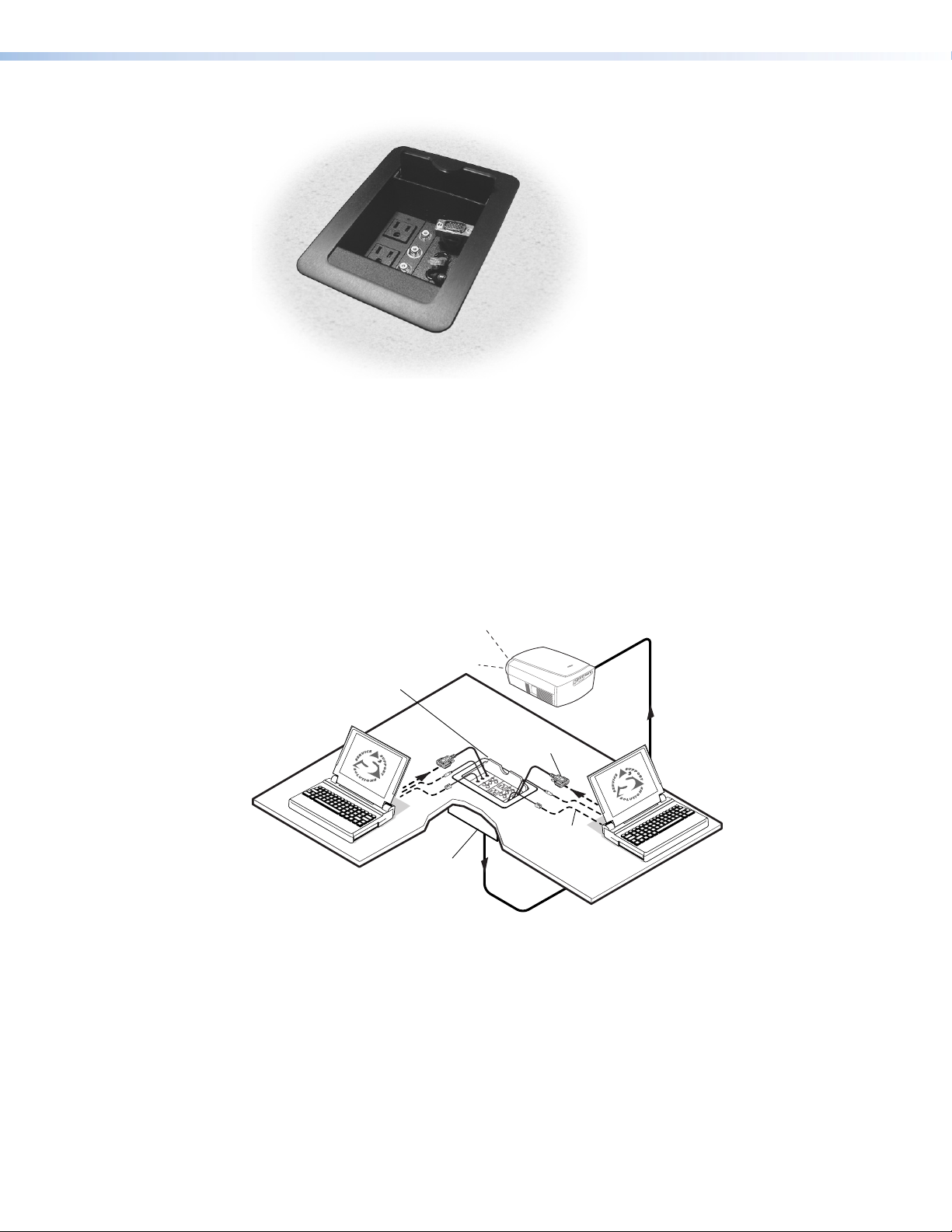
Figure 1. Cable Cubby 300S US/domestic Enclosure
The AAP spaces inside the Cable Cubby allow you to customize the enclosure to meet
your unique needs. The split AAPs (included) can store almost any type of cable you might
encounter. The Extron line of passive AAPs allows you to customize the AAP with almost
any kind of pass-through connectivity you may need.
The elevation of the AAPs inside the cubby and the arrangement of the AAPs and the power
outlets are adjustable to suit cable lengths and connector types.
The installed Cable Cubby fits nearly flush within a table or podium top, storing the AAPs
and cables out of the way and out of sight. To access the AAPs and connectors, lift the lid
(see figure 2). Half-moon cutouts in the lid allow you to run cables in or out and then close
the lid. The lid can also be lowered into its recessed position.
Extron
Cable Cubby 800
Hideaway Cable
Access Enclosure
Mounted
through a table
or podium
15-pin HD Cable
Audio Cable,
Network Cable
Figure 2. Typical Cable Cubby 800 Application
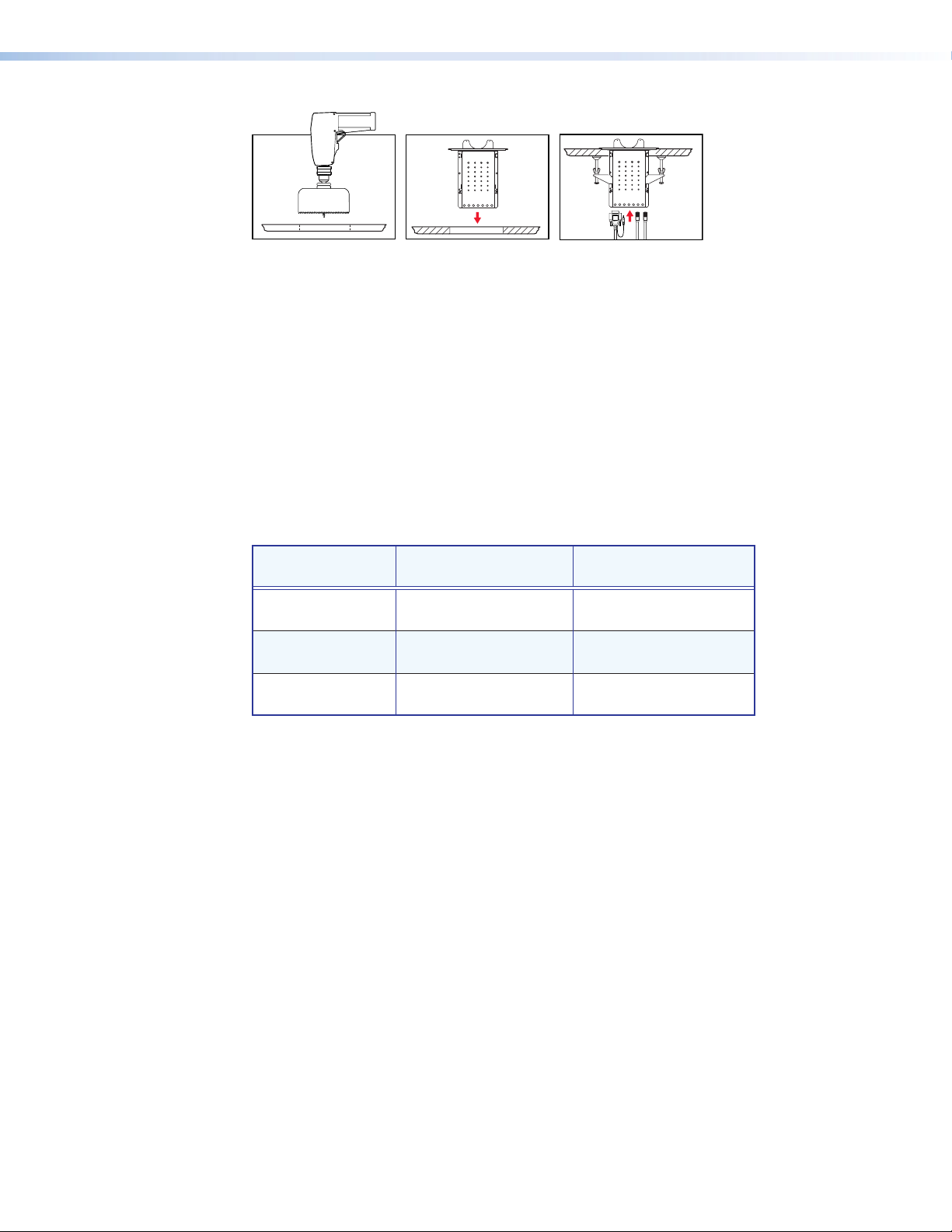
The Cable Cubby 300 is available with either a round or a rectangular top. The other Cable
Cubby models all have rectangular tops only. Preparing the table to install a Cable Cubby
300C (round) requires drilling a hole in the table with a 6-inch hole saw (see figure 3).
Preparing the table to install a square cubby requires routing a square hole in the table top.
Sheet metal routing templates are available (see “Routing Template Part Numbers” on
page 19 for part numbers).
Cable Cubby 300/600/800 • Introduction 2
Page 8
Features
1
Figure 3. Cable Cubby 300C Mounting
• Easy access to cables and AAPs
• Compatible with several available AAP modules
• Optional retractor available
• Compact size
• Flexible installation of Extron passive AAPs
• Available universal AC outlet is compatible with a variety of AC plug types
• UL/c-UL listed and CE compliant
• Fits in a range of surface thicknesses. See the table below:
2 3
Enclosure Minimum Table
Thickness
Cable Cubby 300 0.571 inch (≈19/32 inch)
[14.5 mm]
Cable Cubby 600 0.75 inch (3/4 inch)
[19.05 mm]
Cable Cubby 800 0.75 inch (3/4 inch)
[19.05 mm]
Maximum Table
Thickness
3.23 inch (≈3-1/4 inch)
[82.0 mm]
3.41 inch (≈3-13/32 inch)
[86.6 mm]
3.41 inch (≈3-13/32 inch)
[86.6 mm]
Cable Cubby 300/600/800 • Introduction 3
Page 9

Installation
This section covers the following topics:
• Installation Overview
• Preparing the Routing Template
• Preparing the Table
• Installing the Cables and AAPs
• Mounting the Cable Cubby
Installation Overview
Install and set up the Cable Cubby enclosures as follows:
1. If you plan to use a mounting template that has not been prepared, prepare the
template (see “Preparing the Routing Template” below).
2. Cut a hole in the surface where the enclosure will be installed (see “Preparing the
Table” on the next page).
3. Run all cables necessary to support the AC connector, the cables stored in the cubby,
and all planned AAP connectors. Leave enough slack in the cables to connect or route
them before the cubby is installed in the table.
4. If applicable, install the power module. If your location requires electrical conduit, install
an Extron flexible conduit kit. Refer to the Flexible Conduit Kit Installation Guide, Extron
part number 68-734-01.
5. Install all desired cables into the cable pass-through (split) AAPs and install the AAPs
into the Cable Cubby (see “Installing the Cables and AAPs” on page 7).
6. If applicable, connect cables to the rear connectors on the passive AAPs and install the
AAPs in the cubby (see “Installing the AAPs” on page 10).
7. Mount the Cable Cubby in the table (see “Mounting the Cable Cubby” on page 10).
8. Peel the protective film from the top surface.
9. Connect the Cable Cubby power cord.
Preparing the Routing Template
Extron offers metal templates for each Cable Cubby model; see “Routing Template Part
Numbers” on page 19 for part numbers. Extron recommends using this template as a
guide to cut the hole in the table where the cubby will be installed.
NOTE: The metal routing template is reusable. Do not discard this template when the
installation is complete. Save it for installing Cable Cubby models of the same size.
1. Cut 1/2 inch x 4 inch strips of soft, finished lumber to a length that is long enough to
span the distance between the desired installation location on the mounting surface and
the edges of the mounting surface (see figure 4).
Cable Cubby 300/600/800 • Installation 4
Page 10

These strips raise the routing template above the mounting surface to provide room
for the collar of the router, protect the mounting surface, and extend the reach of the
routing template so that it can be clamped to the edge of the surface.
1/2” x 4” Soft, Finished
Lumber
CABLE CUBBY 300
HSA 200
Preparing the Table
4 Screws Min.
USER ACCESS
HSA 200
USER ACCESS
CABLE CUBBY 300
Width of Mounting Surface
Routing Area
Figure 4. Preparing the CC 300 Mounting Template
2. Using four or more short wood screws, secure the mounting template to the lumber
strips.
ATTENTION: Potential damage to property. Do not allow the wood screws to
protrude through the bottom of the wooden strips. Protruding screws will scratch
the table when the template is used.
The preferred and recommended method for preparing the table for square Cable Cubby
models is to use the appropriate Extron routing template and a router.
For the Cable Cubby 300C, you may use the routing template and a router or use a 6-inch
hole saw.
ATTENTION: Potential damage to property. The opening in the table for the
Cable Cubby should be cut only by licensed and bonded craftspeople. Exercise care to
prevent scarring or damaging the furniture.
ATTENTION: Potential damage to property. The surfaces of the Cable Cubby
enclosure have screws and other protruding hardware that could damage fine furniture.
Do not rest the enclosure on unprotected furniture.
Alternatively, for any model, you can use a paper cut-out template (see “Top Plate
Dimensions” on page 20) and a sabre saw or keyhole saw. However, this method is not
recommended.
Cable Cubby 300/600/800 • Installation 5
Page 11

Preparing the Table with a Router
Prepare the table with a router as follows:
ATTENTION: Potential damage to property. The routing templates for the various
Cable Cubby models are not interchangeable. If you use the wrong template, you will
cut an improperly sized hole. If you use a larger template than required, the cut will
result in gaps in the table surface on either side of the enclosure.
ATTENTION: Potential damage to property. Ensure that only the wooden strips
on the routing template contact the furniture. Failure to do so may scratch the furniture.
NOTE: The metal routing template is reusable. Do not discard the template when the
installation is complete. Save it for installing other Cable Cubby models of the same
size.
1. Mark the desired mounting location on the tabletop or other installation surface.
2. Place the mounting template assembly on the table, centered on the mounting location.
Angle the template for the optimum positioning. If necessary, use a square to ensure
that the template is properly positioned. Extron is not responsible for an improperly
positioned Cable Cubby.
3. Once the template assembly is positioned properly, secure the assembly to the table
with C-clamps.
CAUTION: Risk of injury to the eyes. Wear safety glasses when operating the
router. Failure to comply can result in eye injury.
4. Using a router with a 5/8 inch (or 16 mm) outside diameter guide bushing and a
1/2 inch (or 12 mm or 12.7 mm) diameter straight router bit, carefully cut the opening in
the surface (see figure 5).
Router
CABLE CUBBY 300
HSA 200
USER ACCESS
HSA 200
CABLE CUBBY 300
USER ACCESS
Figure 5. Cutting the Opening with a Router
5. Remove the C-clamps and the routing template.
Cable Cubby 300/600/800 • Installation 6
Page 12

Preparing the Table with a Hole Saw (Cable Cubby 300C Only)
Prepare the table with a hole saw as follows:
1. On the tabletop or other installation surface, mark the 6 inch circle, then find and mark
the center of the circle.
CAUTION: Risk of injury to the eyes. Wear safety glasses when operating the
drill. Failure to comply can result in eye injury.
2. Using a portable drill with a 6-inch (or 152 mm) hole saw, carefully cut the opening in
the table surface at the desired location (see figure 6). Extron is not responsible for an
improperly positioned Cable Cubby.
ATTENTION: Potential damage to property. Use a portable drill with sufficient
power to handle the 6-inch hole saw. Exercise caution when handling the drill and
hole saw. Take care to protect the mounting surface from damage.
Figure 6. Cutting the Opening with a Hole Saw
Installing the Cables and AAPs
Each Cable Cubby model ships with one or two moveable AAP shelf assemblies.
AAP Shelf Brackets
Each shipped AAP shelf assembly consists of a set of shelf brackets and a number of cable
pass-through (split) AAPs. Depending on the Cable Cubby model, each set of shelf brackets
supports either two-, three-, or four-space AAPs (see figure 7).
Four-Space Shelf Bracket
and Split AAPs
Three-Space Shelf Bracket
and Split AAPs
Two-Space Shelf Bracket
and Split AAPs
Figure 7. Shelf Brackets
Cable Cubby 300/600/800 • Installation 7
Page 13

The simplest way to install the cables and AAPs in the Cable Cubby 300, 600, and 800 is to
populate the shelf brackets with split or standard AAPs outside the cubby and then install
the populated AAP shelf assembly into the cubby.
NOTE: On US/domestic models, the power module takes up two AAP spaces. Cable
pass-through AAPs take two, three, or four AAP spaces. Consider the arrangement of
the Cable Cubby AAPs when you install them so that you do not waste AAP space.
Installing the Power Module
From the underside of the Cable Cubby, gently push the power module into the desired
position at the desired elevation. Secure the power module into position with four Phillips
head screws (see figure 8).
NOTE: The universal AC outlet is fully compatible with various plug types. See the
Universal AC Outlet Compatibility Guide on the Extron website, www.extron.com, for
compatibility details on all plug types.
ATTENTION: Potential damage to property. To ensure good electrical grounding,
use the star washers with the screws.
Extron
Cable Cubby 600
2 Screws ea. side
Figure 8. Installing the Power Module
Cable Cubby 300/600/800 • Installation 8
Page 14

Installing the Cables
Three half-moon cutouts in each set of cable pass-through (split) AAPs loosely channel
three cables in the Cable Cubby. Each channel is padded with a split grommet to prevent
cable wear. Each channel and each associated split grommet is a different size
(see figure 9).
Small
Medium
Large
Cable Hole Hole SizeGrommet Size
Large 0.625" (1.59 cm) 0.453" (1.15 cm)
Medium 0.562" (1.43 cm) 0.390" (0.99 cm)
Small 0.5" (1.27 cm) 0.312" (0.79 cm)
Figure 9. Cable Pass-through AAPs
Large
Small
Medium
Medium
Small
Large
A typical installation consists of a VGA cable, an audio cable, and a network cable. In a
typical installation, the VGA cable runs in the largest channel, the network cable runs in the
middle (medium) channel, and the audio cable runs in the smaller channel. In a
non-standard installation, match the diameter of the cable to the size of the channel as best
you can.
Install cables in the channels as follows:
1. Remove a segment of a set of split AAPs by unscrewing the nuts on the underside of
the bracket that fastens the plate to the shelf bracket (see figure 7, on page 7).
2. Rest the cables in the half-moon cutouts of the split AAP segment still mounted on the
shelf brackets. Place the cables so that the connectors protrude from the front of the
split AAP segment.
3. Insert the screws of the split AAP segment that you removed in step 1 through the holes
in the shelf bracket. Ensure that the cables are free in the channels that the two split
AAP segments form without being pinched where the two segments meet.
4. Secure the split AAP segment to the shelf brackets with the provided captive washers
and #4-40 nuts.
5. Slip the appropriate size split grommet over each
cable with the flange of the grommet toward the
connector that will be accessible inside the Cable
Cubby. Snap the grommets into the channels.
6. If applicable, snap the included hole plugs into unused
channels in place of the split grommets.
Cable Cubby 300/600/800 • Installation 9
Page 15

Installing the AAPs
The split AAPs can be replaced with passive Extron AAPs.
Replace a set of split AAPs as follows:
1. Remove the set of split AAPs to be replaced by unscrewing the nuts on the underside
of the shelf bracket that fasten the plates to the bracket (see figure 7, on page 7).
2. Cable the AAP(s) before attaching the AAPs to the enclosure.
3. Insert the screws of the AAPs through the holes in the shelf or shelf bracket. Secure the
AAPs to the shelf brackets with the provided captive washers and #4-40 nuts.
Installing the Shelf Assembly
From the underside of the Cable Cubby, gently push the AAP shelf assembly into the
desired position at the desired elevation. Ensure there is enough space above the AAP
assembly for the Cable Cubby lid to close completely. Secure the AAP shelf assembly into
position with four Phillips head screws.
NOTE: If the AAP shelf assembly does not slide easily into the cubby, loosen the AAP
mounting nuts. Retighten the AAP mounting nuts once the AAP shelf assembly is
installed in position.
Mounting the Cable Cubby
CAUTION: Risk of personal injury. The flanged edges of the top of the surface
enclosure are sharp. Exercise caution when the cubby is not installed in a table to
prevent personal injury.
ATTENTION: Potential damage to property. The flanged edges of the top
of the cubby are bevelled to an ultra-fine thickness of less than 0.04 inch (4/100
1. If screw clamps are installed, remove them from both sides of the
2. Remove the plastic strips that protect the corners of the enclosure and the plastic film
3. Carefully lower the Cable Cubby into the hole to test the fit. If necessary, remove the
inch; approximately 1 mm). These edges are soft and can be easily nicked or bent.
Exercise caution when handling and mounting the enclosure. Mishandling can
damage the appearance of the enclosure.
enclosure (see figure 10 on the next page).
NOTE: Figure 10 shows the installation of a Cable Cubby 300C.
Cable Cubby 300S, 600, and 800 installations are similar.
on the finished surfaces. If a sticky residue remains, remove it with an appropriate metal
cleaning product.
ATTENTION: Potential damage to property. Do not use isopropyl alcohol or
other solvents to clean the Cable Cubby. Strong solvents will ruin some finishes.
enclosure and use a file or rasp to enlarge or smooth the edges of the opening
(see figure 10 on the next page).
Cable Cubby 300/600/800 • Installation 10
Page 16

15-pin HD Cable
Audio Cable
RJ-45 Cable
Cable Cubby 300C
Surface-Mountable
Enclosure for Cables, AAPs,
and AC Power Outlet
Mounting
Surface
Screw Clamp
Figure 10. Cable Cubby 300C, Installation View
4. From the underside of the table, reinstall the screw clamps on the enclosure at a height
at which the clamp will reach the underside of the tabletop.
ATTENTION: Potential damage to property. Do not overtighten the Phillips
head screws on the screw clamps. Overtightening can bend the horizontal flange of
the screw clamp.
5. Snugly tighten the Phillips head screws on the screw clamps to secure the enclosure to
the surface.
6. Tighten the locking thumbscrews on the screw clamps to lock the clamp in position.
Cable Cubby 300/600/800 • Installation 11
Page 17

Maintenance and
Modifications
This section covers the following topics:
• Removing and Replacing the Cable Cubby
• Replacing Cables or an AAP
• Adding an Additional Power Module (CC 600, CC 800)
The Cable Cubby can be modified after installation to change cables, to replace an AAP, or
to add a second power module. These modifications may require removing the cubby from
the table.
Removing and Replacing the Cable Cubby
You may need to remove the cubby from the table in which it is mounted to replace cables
or AAPs, to adjust the height of the AAP assemblies, or to install a second power module.
Figure 11 on the next page shows removal of the Cable Cubby 300, 600, or 800 from the
table and removal of the AAP shelf assembly and power module.
Remove and replace the Cable Cubby for maintenance as follows:
CAUTION: Risk of electrical shock. Ensure that AC power is disconnected before
servicing the Cable Cubby.
1. Loosen the locking thumbscrews on the screw clamps to unlock the
clamp (see figure 11).
2. Loosen the screw clamps.
3. Remove the screw clamps on both sides of the enclosure.
Cable Cubby 300/600/800 • Maintenance and Modifications 12
Page 18

Extron
Cable Cubby 800
Pins
Phillips Head Screw
(Secures AAP Shelf Assembly
and Power Module.)
Screw Clamp
Figure 11. Removing the Cubby and its Shelves
4. Lift the enclosure from the table.
CAUTION: Risk of personal injury. The flanged edges of the top of the surface
enclosure are sharp. Exercise caution when the cubby is not installed in a table to
prevent personal injury.
ATTENTION: Potential Damage to Property. The flanged edges of the top
of the cubby are bevelled to an ultra-fine thickness of less than 0.04 inch (4/100
inch; approximately 1 mm). These edges are soft and can be easily nicked or bent.
Exercise caution when handling and mounting the enclosure. Mishandling can
damage the appearance of the enclosure.
5. Remove the AAP shelf assembly(ies) or power module by removing the four Phillips
head screws on the front and rear of the Cable Cubby and gently pushing the
assembly(ies) out through the top or bottom of the cubby.
6. Perform the desired maintenance procedure.
7. Reinstall the AAP shelf assembly(ies).
8. Carefully lower the Cable Cubby into the hole in the table.
9. From the underside of the table, reinstall the screw clamps on the enclosure at a height
at which the clamp will reach the underside of the tabletop.
Cable Cubby 300/600/800 • Maintenance and Modifications 13
Page 19

ATTENTION: Potential damage to property. Do not overtighten the Phillips
head screws on the screw clamps. Overtightening can bend the horizontal flange of
the screw clamp.
10. Snugly tighten the Phillips head screws on the screw clamps to secure the enclosure to
the surface.
11. Tighten the locking thumbscrews on the screw clamps to lock the clamp in position.
Replacing Cables or an AAP
Before you change the cables or replace one or more AAPs inside the cubby, you must
remove the AAP shelf assembly from the Cable Cubby. Use the following guidelines as
applicable:
1. If the Phillips head screws on the front and rear of the cubby are blocked by the table,
remove the cubby from the table. See “Removing and Replacing the Cable Cubby”
steps 1 through 4, on page 12.
2. Remove the AAP shelf assembly(ies) by removing the four Phillips head screws on the
front and rear of the Cable Cubby and gently pushing the assembly out through the
bottom of the cubby.
3. Change the cables and AAPs the same way you installed them. See “Installing the
Cables and AAPs” on page 7.
4. If you removed the cubby from the table, reinstall the enclosure. See “Removing and
Replacing the Cable Cubby,” steps 7 through 10, on page 13.
Adding an Additional Power Module (CC 600 and CC 800)
Each additional USA/domestic power module occupies two AAP spaces, and each
international power module (optional) occupies three AAP spaces. Additional power
modules reduce the amount of AAP space available in the cubby for cable pass-through
(split) or passive AAPs. Use the following guidelines as applicable:
NOTE: The universal AC outlet is fully compatible with various plug types. See the
Universal AC Outlet Compatibility Guide on the Extron website, www.extron.com, for
compatibility details on all plug types.
1. Replacement two-space, three-space, and four-space shelf brackets and cable
pass-through (split) AAPs are available from Extron, and may be required to maximize
the remaining available space if you add a power module.
• Cable Cubby 300 models — Adding a second power module is not
recommended. With a second power module, there is either room left for only a
single one-space AAP or no AAP space left at all (depending on the model).
• Cable Cubby 600 and 800 (AC module optional) — In general, you probably do
not need replacement shelf brackets when you add an international module to a
Cable Cubby with no pre-installed power module. The power module replaces a
three-space shelf that is standard in all Cable Cubby models with no pre-installed
power module.
Figure 12 on the next page shows the typical configurations of one and two
international power modules installed in a Cable Cubby 600 with no pre-installed
power module.
Cable Cubby 300/600/800 • Maintenance and Modifications 14
Page 20

Single Power Module
Three AAP
Space Shelf
Two AAP
Space Shelf
Two AAP
Space Shelf
Two Power Modules
UNSWITCHED
230~50/60Hz
5A
UNSWITCHED
230~50/60Hz
5A
UNSWITCHED
230~50/60Hz
5A
Single Power Module
Two Power Modules
Four AAP
Space Shelf
Four AAP
Space Shelf
Three AAP
Space Shelf
UNSWITCHED
230~50/60Hz
5A
UNSWITCHED
230~50/60Hz
5A
UNSWITCHED
230~50/60Hz
5A
Figure 12. Cable Cubby 600 with Power Module(s)
Figure 13 shows the typical configurations of one and two international power
modules installed in a Cable Cubby 800 with no pre-installed power module.
Figure 13. Cable Cubby 800 with Power Module(s)
• Cable Cubby 600 and 800 US/domestic models — You probably do need
replacement shelf brackets when you add a US/domestic power module to a
US/domestic Cable Cubby. This is because the power module takes up two spaces
in a cubby that, in its standard configuration, is equipped with three-space (Cable
Cubby 600) or four-space (Cable Cubby 800) shelves.
Figure 14 on the next page shows typical configurations before and after you add
a second US/domestic power module to a US/domestic Cable Cubby 600 and
suggests rack shelf configurations to replace the lost shelf space.
Cable Cubby 300/600/800 • Maintenance and Modifications 15
Page 21

Before
UNSWITCHED
100-240V/ 5AMAX
UNSWITCHED
100-240V/ 5AMAX
After
UNSWITCHED
100-240V/ 5AMAX
UNSWITCHED
100-240V/ 5AMAX
UNSWITCHED
100-240V/ 5AMAX
UNSWITCHED
100-240V/ 5AMAX
Three AAP
Space Shelf
Three AAP
Space Shelf
Four AAP
Space Shelf
or
UNSWITCHED
100-240V/ 5AMAX
UNSWITCHED
100-240V/ 5AMAX
Two AAP
Space Shelf
Two AAP
Space Shelf
UNSWITCHED
100-240V/ 5AMAX
UNSWITCHED
100-240V/ 5AMAX
Figure 14. Cable Cubby 600 with Second Power Module
Figure 15 shows typical configurations before and after you add a second
US/domestic power module to a US/domestic Cable Cubby 800 and suggests rack
shelf configurations to replace the lost shelf space.
UNSWITCHED
100-240V/ 5AMAX
UNSWITCHED
After
UNSWITCHED
100-240V/ 5AMAX
UNSWITCHED
Before
UNSWITCHED
100-240V/ 5AMAX
UNSWITCHED
100-240V/ 5AMAX
100-240V/ 5AMAX
Two AAP
Space Shelf
Four AAP
Space Shelf
Four AAP
Space Shelf
100-240V/ 5AMAX
Four AAP
Space Shelf
or
UNSWITCHED
UNSWITCHED
VIDEO AUDIO
Three AAP
Space Shelf
LR
100-240V/ 5AMAX
UNSWITCHED
100-240V/ 5AMAX
100-240V/ 5AMAX
UNSWITCHED
100-240V/ 5AMAX
Three AAP
Space Shelf
LR
VIDEO AUDIO
Figure 15. Cable Cubby 800 with Second Power Module
Cable Cubby 300/600/800 • Maintenance and Modifications 16
Page 22

2. If the Phillips head screws on the front and rear of the cubby are blocked by the table,
2 Screws ea. side
Extron
Cable Cubby 600
remove the cubby from the table (see “Removing and Replacing the Cable Cubby,”
steps 1 through 4, on page 12).
3. Before you add an additional power module, you must make room for the Cable Cubby
by eliminating two or three AAP spaces and the AAP shelf brackets that support them.
Remove the Phillips head screws on the front and rear of the Cable Cubby and gently
push the assembly(ies) out through the bottom of the cubby.
4. From the underside of the Cable Cubby, gently push the additional power module into
the desired position at the desired elevation. Secure the power module into position
with the four included Phillips head screws (see figure 16).
ATTENTION: Potential damage to property. To ensure good electrical
grounding, use the star washers with the screws.
Figure 16. Installing the Power Module
5. If desired, assemble and install replacement AAP shelf assemblies. Remember that
the cable pull function of the Cable Cubby requires at least a two-space AAP (see
“Installing the Cables and AAPs” on page 7).
6. If you removed the cubby from the table, reinstall the enclosure (see “Removing and
Replacing the Cable Cubby” steps 7 through 10, on page 13).
Cable Cubby 300/600/800 • Maintenance and Modifications 17
Page 23

Reference
Information
This section covers the following topics:
• Cable Cubby Part Numbers
• Included Parts
• Replacement/Modification Part Numbers
• Routing Template Part Numbers
• Top Plate Dimensions
Cable Cubby Part Numbers
Cable Cubby 300S Part Number
Cable Cubby 300S US/domestic (black anodized finish) 60-526-01
Cable Cubby 300S (black, AC module optional) 60-712-00
Cable Cubby 300S (brushed aluminum, AC module optional) 60-712-10
Cable Cubby 300C Part Number
Cable Cubby 300C/domestic (black anodized finish) 60-527-01
Cable Cubby 300C (black, AC module optional) 60-713-00
Cable Cubby 300C (brushed aluminum, AC module optional) 60-713-10
Cable Cubby 600 Part Number
Cable Cubby 600 US/domestic (black anodized finish) 60-525-01
Cable Cubby 600 (black, AC module optional) 60-714-00
Cable Cubby 600 (brushed aluminum, AC module optional) 60-714-10
Cable Cubby 800 Part Number
Cable Cubby 800 US/domestic (black anodized finish) 60-524-01
Cable Cubby 800 (black, AC module optional) 60-715-00
Cable Cubby 800 (brushed aluminum, AC module optional) 60-715-10
Cable Cubby 300/600/800 • Reference Information 18
Page 24

Included Parts
The Cable Cubby includes the Cable Cubby Setup Guide and a selection of shelf brackets,
cable pass-through AAPs, grommets, and hole plugs that vary depending on the
Cable Cubby model. See the table below for included parts:
Large
Small
Medium
Large
Medium
Small
Small
Medium
Large
AAP Cable
Pass Through
Left
70-270-01
AAP Cable
Pass Through
Left Middle
70-269-01
AAP Cable
Pass Through
Right Middle
70-268-01
AAP Shelf Brackets Pass-through AAPs*
Model 2 Pos. 3 Pos. 4 Pos. L L-M R-M R
CC 300 US 0 2 0 1 0 1 2
CC 300 (AC module optional) 2 2 0 1 0 0 1
CC 600 US 0 4 0 2 2 2 2
CC 600 (AC module optional) 4 0 2 3 2 1 1
CC 800 US 0 0 4 2 3 3 2
CC 800 (AC module optional) 0 4 2 3 3 2 1
* L = left, L-M = left middle, R-M = right middle, R = right
All CC 300S and CC 300C models have the same AAP configuration
Replacement/Modication Part Numbers
NOTE: See www.extron.com for replacement part numbers.
AAP Cable
Pass Through
Right
70-267-01
Routing Template Part Numbers
The following reusable sheet metal routing templates are recommended for installation.
Template Part Number
Cable Cubby 300S/300C routing template 70-237-01
Cable Cubby 600 routing template 70-239-01
Cable Cubby 800 routing template 70-240-01
Cable Cubby 300/600/800 • Reference Information 19
Page 25

Top Plate Dimensions
There are two preferred and recommended methods for cutting the table: using
appropriate metal routing template (see figure 19 below a
using a router or a hole saw (Cable Cubby 300C only).
Figure 17. CC 300S and 300C Metal Routing Template
If you choose not to use Extron metal routing templates, the cut-out templates (see
figure 18, figure 19, figure 20, and figure 21 on the next page) will help you prepare the
mounting surface. The cut-out templates are not to scale and are for reference only. For
full size paper templates, visit www.extron.com or call the Extron S3 Sales and Technical
Support Hotline.
HSA 200
CABLE CUBBY 300
HSA 200
USER ACCESS
the
nd Installation on page 4), and
CABLE CUBBY 300
USER ACCESS
Cable Cubby 300/600/800 • Reference Information 20
Page 26

Cut-Out Template for
Cut-Out Template for
Cut-Out Template for
Cut-Out Template for
Cable Cubby 300S
5.13" (13.0 cm)
4.625"
(11.7 cm)
6.47"
(16.4 cm)
Cut surface material
out along this line.
SURFACE CUT-OUT
5.97"
(15.2 cm)
User Access
AREA =
(11.7 cm) x
(15.2 cm)
Top Panel
4.625"
5.97"
0.5"
(1.3 cm)
Cut-Out Radius:
0.25"
(0.6 cm)
TEMPLATE IS NOT FULL SIZE.
Figure 18. Cable Cubby 300S Cut-Out Template
Cable Cubby 600
6.96" (17.7 cm)
Cable Cubby 300C
6.5" Dia.
(16.51 cm)
6.0" Dia.
(15.24 cm)
SURFACE CUT-OUT
AREA =
6.0" Dia.
User Access
TEMPLATE IS NOT FULL SIZE.
Figure 19. Cable Cubby 300C Cut-Out Template
Cable Cubby 800
8.36" (21.23 cm)
6.46"
(16.41 cm)
6.96"
(17.7 cm)
Figure 20. Cable Cubby 600 Cut-Out Template
6.46"
(16.41 cm)
Cut surface material
out along this line.
SURFACE CUT-OUT
AREA =
6.46"(16.41 cm) x
6.46"(16.41 cm)
Top Panel
User Access
TEMPLATE IS NOT FULL SIZE.
Cut-Out Radius:
0.25"
(0.6 cm)
0.5"
(1.3 cm)
7.86"
(20.0 cm)
6.82"
6.32"
(16.1 cm)
Cut surface material
out along this line.
SURFACE CUT-OUT
AREA =
7.86"(20.0 cm) x
6.32"(16.1 cm)
Top Panel
User Access
0.5"
(1.3 cm)
Cut-Out Radius:
0.25"
(0.6 cm)
TEMPLATE IS NOT FULL SIZE.
Figure 21. Cable Cubby 800 Cut-Out Template
Cable Cubby 300/600/800 • Reference Information 21
Page 27

Extron Warranty
Extron Electronics warrants this product against defects in materials and workmanship for a period of three years
from the date of purchase. In the event of malfunction during the warranty period attributable directly to faulty
workmanship and/or materials, Extron Electronics will, at its option, repair or replace said products or components,
to whatever extent it shall deem necessary to restore said product to proper operating condition, provided that it is
returned within the warranty period, with proof of purchase and description of malfunction to:
USA, Canada, South America
and Central America:
Extron Electronics
1001 East Ball Road
Anaheim, CA 92805
U.S.A.
Europe and Africa:
Extron Europe
Hanzeboulevard 10
3825 PH Amersfoort
The Netherlands
Japan:
Extron Electronics, Japan
Kyodo Building, 16 Ichibancho
Chiyoda-ku, Tokyo 102-0082
Japan
China:
Extron China
686 Ronghua Road
Songjiang District
Shanghai 201611
China
Asia:
Extron Asia
135 Joo Seng Road, #04-01
PM Industrial Bldg.
Singapore 368363
Middle East:
Extron Middle East
Dubai Airport Free Zone
F12, PO Box 293666
United Arab Emirates, Dubai
Singapore
This Limited Warranty does not apply if the fault has been caused by misuse, improper handling care, electrical
or mechanical abuse, abnormal operating conditions, or if modifications were made to the product that were not
authorized by Extron.
NOTE: If a product is defective, please call Extron and ask for an Application Engineer to receive an RA (Return
Authorization) number. This will begin the repair process.
USA: 714.491.1500 or 800.633.9876 Europe: 31.33.453.4040
Asia: 65.6383.4400 Japan: 81.3.3511.7655
Units must be returned insured, with shipping charges prepaid. If not insured, you assume the risk of loss or damage
during shipment. Returned units must include the serial number and a description of the problem, as well as the
name of the person to contact in case there are any questions.
Extron Electronics makes no further warranties either expressed or implied with respect to the product and its quality,
performance, merchantability, or fitness for any particular use. In no event will Extron Electronics be liable for direct,
indirect, or consequential damages resulting from any defect in this product even if Extron Electronics has been
advised of such damage.
Please note that laws vary from state to state and country to country, and that some provisions of this warranty may
not apply to you.
Extron Headquarters
+1.800.633.9876 (Inside USA/Canada Only)
Extron USA - West Extron USA - East
+1.714.491.1500 +1.919.850.1000
+1.714.491.1517 FAX +1.919.850.1001 FAX
Extron Europe
+800.3987.6673
(Inside Europe Only)
+31.33.453.4040
+31.33.453.4050 FAX
© 2012 Extron Electronics All rights reserved. www.extron.com
Extron Asia
+800.7339.8766
(Inside Asia Only)
+65.6383.4400
+65.6383.4664 FAX
Extron Japan
+81.3.3511.7655
+81.3.3511.7656 FAX
Extron China
+4000.398766
Inside China Only
+86.21.3760.1568
+86.21.3760.1566 FAX
Extron Middle East
+971.4.2991800
+971.4.2991880 FAX
Extron Korea
+82.2.3444.1571
+82.2.3444.1575 FAX
Extron India
1800.3070.3777
Inside India Only
+91.80.3055.3777
+91.80.3055.3737 FAX
 Loading...