

Page 1

XTP II CrossPoint Series
Configurable Digital Video Matrix Switchers
User Guide
XTP Systems
68-1736-02 Rev. J
01 21
Page 2
Safety Instructions
Safety Instructions • English
WARNING: This symbol, , when used on the product, is intended to
alert the user of the presence of uninsulated dangerous voltage within the
product’s enclosure that may present a risk of electric shock.
ATTENTION: This symbol, , when used on the product, is intended
to alert the user of important operating and maintenance (servicing)
instructions in the literature provided with the equipment.
For information on safety guidelines, regulatory compliances, EMI/EMF
compatibility, accessibility, and related topics, see the Extron Safety and
Regulatory Compliance Guide, part number 68-290-01, on the Extron website,
www.extron.com.
Sicherheitsanweisungen • Deutsch
WARUNG: Dieses Symbol auf demProdukt soll den Benutzer darauf
aufmerksam machen, dass im Inneren des Gehäuses dieses Produktes
gefährliche Spannungen herrschen, die nicht isoliert sind und die einen
elektrischen Schlag verursachen können.
VORSICHT: Dieses Symbol auf dem Produkt soll dem Benutzer in der im
Lieferumfang enthaltenen Dokumentation besonders wichtige Hinweise
zur Bedienung und Wartung (Instandhaltung) geben.
Weitere Informationen über die Sicherheitsrichtlinien, Produkthandhabung,
EMI/EMF-Kompatibilität, Zugänglichkeit und verwandte Themen finden Sie in den
Extron-Richtlinien für Sicherheit und Handhabung (Artikelnummer
68-290-01) auf der Extron-Website, www.extron.com.
Instrucciones de seguridad • Español
ADVERTENCIA: Este símbolo, , cuando se utiliza en el producto, avisa
al usuario de la presencia de voltaje peligroso sin aislar dentro del
producto, lo que puede representar un riesgo de descarga eléctrica.
ATENCIÓN: Este símbolo, , cuando se utiliza en el producto, avisa
al usuario de la presencia de importantes instrucciones de uso y
mantenimiento estas estan incluidas en la documentación proporcionada
con el equipo.
Para obtener información sobre directrices de seguridad, cumplimiento
de normativas, compatibilidad electromagnética, accesibilidad y temas
relacionados, consulte la Guía de cumplimiento de normativas y seguridad de
Extron, referencia 68-290-01, en el sitio Web de Extron, www.extron.com.
Instructions de sécurité • Français
AVERTISSEMENT : Ce pictogramme, , lorsqu’il est utilisé sur le
produit, signale à l’utilisateur la présence à l’intérieur du boîtier du produit
d’une tension électrique dangereuse susceptible de provoquer un choc
électrique.
ATTENTION : Ce pictogramme, , lorsqu’il est utilisé sur le produit, signale
à l’utilisateur des instructions d’utilisation ou de maintenance importantes
qui se trouvent dans la documentation fournie avec l’équipement.
Pour en savoir plus sur les règles de sécurité, la conformité à la réglementation,
la compatibilité EMI/EMF, l’accessibilité, et autres sujets connexes, lisez les
informations de sécurité et de conformité Extron, réf. 68-290-01, sur le site
Extron, www.extron.com.
Istruzioni di sicurezza • Italiano
AVVERTENZA: Il simbolo, , se usato sul prodotto, serve ad avvertire
l’utente della presenza di tensione non isolata pericolosa all’interno
del contenitore del prodotto che può costituire un rischio di scosse
elettriche.
ATTENTZIONE: Il simbolo, , se usato sul prodotto, serve ad avvertire
l’utente della presenza di importanti istruzioni di funzionamento e
manutenzione nella documentazione fornita con l’apparecchio.
Per informazioni su parametri di sicurezza, conformità alle normative,
compatibilità EMI/EMF, accessibilità e argomenti simili, fare riferimento alla Guida
alla conformità normativa e di sicurezza di Extron, cod. articolo 68-290-01, sul
sito web di Extron, www.extron.com.
Instrukcje bezpieczeństwa • Polska
OSTRZEŻENIE: Ten symbol, , gdy używany na produkt, ma na celu
poinformować użytkownika o obecności izolowanego i niebezpiecznego
napięcia wewnątrz obudowy produktu, który może stanowić zagrożenie
porażenia prądem elektrycznym.
UWAGI: Ten symbol, , gdy używany na produkt, jest przeznaczony do
ostrzegania użytkownika ważne operacyjne oraz instrukcje konserwacji
(obsługi) w literaturze, wyposażone w sprzęt.
Informacji na temat wytycznych w sprawie bezpieczeństwa, regulacji wzajemnej
zgodności, zgodność EMI/EMF, dostępności i Tematy pokrewne, zobacz Extron
bezpieczeństwa i regulacyjnego zgodności przewodnik, część numer 68-290-01,
na stronie internetowej Extron, www.extron.com.
Инструкция по технике безопасности • Русский
ПРЕДУПРЕЖДЕНИЕ: Данный символ, , если указан
на продукте, предупреждает пользователя о наличии
неизолированного опасного напряжения внутри корпуса
продукта, которое может привести к поражению электрическим
током.
ВНИМАНИЕ: Данный символ, , если указан на продукте,
предупреждает пользователя о наличии важных инструкций по
эксплуатации и обслуживанию в руководстве, прилагаемом к
данному оборудованию.
Для получения информации о правилах техники безопасности,
соблюдении нормативных требований, электромагнитной
совместимости (ЭМП/ЭДС), возможности доступа и других вопросах
см. руководство по безопасности и соблюдению нормативных
требований Extron на сайте Extron: , www.extron.com,
номер по каталогу - 68-290-01.
安全说明 • 简体中文
警告: 产品上的这个标志意在警告用户, 该产品机壳内有暴露的危险
电 压 ,有 触 电 危 险 。
注意: 产品上的这个标志意在提示用户, 设备随附的用户手册中有重
要的操作和维护(维修)说明。
关于我们产品的安全指南、遵循的规范、EMI/EMF 的兼容性、无障碍使
用的特性等相关内容,
敬请访问 Extron 网站 , www.extron.com,参见 Extron 安全规范指南,产品编号
68-290-01。
Page 3

安全記事 • 繁體中文
警告: 若產品上使用此符 號,是為了提醒使用者,產品機殼內存在未隔離的危險
電壓,可能會導致觸電之風險。
注意 若產品上使用此符號,是為了提醒使用者,設備隨附的用戶手冊中有重要
的 操 作 和 維 護( 維 修 )説 明 。
有關安全性指導方針、法規遵守、EMI/EMF 相容性、存取範圍和相關主題的詳細資訊,
請瀏覽 Extron 網站:www.extron.com,然後參閱《Extron 安全性與法規遵守手
冊》,準則編號 68-290-01。
안전 지침 • 한국어
경고: 이 기호 가 제품에 사용될 경우, 제품의 인클로저 내에 있는
접지되지 않은 위험한 전류로 인해 사용자가 감전될 위험이 있음을
경고합니다.
주의: 이 기호 가 제품에 사용될 경우, 장비와 함께 제공된 책자에 나와
있는 주요 운영 및 유지보수(정비) 지침을 경고합니다.
안전 가이드라인, 규제 준수, EMI/EMF 호환성, 접근성, 그리고 관련 항목에 대한
자세한 내용은 Extron 웹 사이트(www.extron.com)의 Extron 안전 및 규제
준수 안내서, 68-290-01 조항을 참조하십시오.
Copyright
© 2015-2021 Extron. All rights reserved. www.extron.com
Trademarks
All trademarks mentioned in this guide are the properties of their respective owners.
The following registered trademarks (®), registered service marks (SM), and trademarks (TM) are the property of RGBSystems, Inc. or Extron (see the
current list of trademarks on the T
erms of Use page at www.extron.com):
Registered Trademarks (
®
)
Extron, Cable Cubby, ControlScript, CrossPoint, DTP, eBUS, EDID Manager, EDID Minder, eLink, Flat Field, FlexOS, Glitch Free, GlobalConfigurator,
GlobalScripter, GlobalViewer, Hideaway, HyperLane, IPIntercom, IPLink, KeyMinder, LinkLicense, LockIt, MediaLink, MediaPort, NAV,
NetPA, PlenumVault, PoleVault, PowerCage, PURE3, Quantum, ShareLink, Show Me, SoundField, SpeedMount, SpeedSwitch, StudioStation,
SystemINTEGRATOR, TeamWork, TouchLink, V-Lock, VideoLounge, VN-Matrix, VoiceLift, WallVault, WindoWall, XPA, XTP, XTPSystems, and ZipClip
Registered Service Mark
(SM)
: S3 Service Support Solutions
Trademarks
(™)
AAP, AFL (Accu-RATEFrameLock), ADSP(Advanced Digital Sync Processing), Auto-Image, AVEdge, CableCover, CDRS(ClassD Ripple
Suppression), Codec Connect, DDSP(Digital Display Sync Processing), DMI (DynamicMotionInterpolation), DriverConfigurator, DSPConfigurator,
DSVP(Digital Sync Validation Processing), EQIP, Everlast, FastBite, Flex55, FOX, FOXBOX, IP Intercom HelpDesk, MAAP, MicroDigital, Opti-Torque,
PendantConnect, ProDSP, QS-FPC(QuickSwitch Front Panel Controller), RoomAgent, Scope-Trigger, SIS, SimpleInstructionSet, Skew-Free,
SpeedNav, Triple-Action Switching, True4K, True8K, Vector™ 4K, WebShare, XTRA, and ZipCaddy
Page 4

FCC Class A Notice
This equipment has been tested and found to comply with the limits for a Class A digital
device, pursuant to part15 of the FCC rules. The ClassA limits provide reasonable
protection against harmful interference when the equipment is operated in a commercial
environment. This equipment generates, uses, and can radiate radio frequency energy and,
if not installed and used in accordance with the instruction manual, may cause harmful
interference to radio communications. Operation of this equipment in a residential area is
likely to cause interference. This interference must be corrected at the expense of the user.
ATTENTION: The Twisted Pair Extension technology works with unshielded twisted
pair (UTP) or shielded twisted pair (STP) cables; but to ensure FCC Class A and CE
compliance, STP cables and STP Connectors are required.
For more information on safety guidelines, regulatory compliances, EMI/EMF
compatibility, accessibility, and related topics, see the “Extron Safety and Regulatory
Compliance Guide” on the Extron website.
Battery Notice
This product contains a battery. Do not open the unit to replace the battery. If the
battery needs replacing, return the entire unit to Extron (for the correct address, see the
Extron Warranty section on the last page of this guide).
CAUTION: Risk of explosion. Do not replace the battery with an incorrect type. Dispose
of used batteries according to the instructions.
ATTENTION : Risque d’explosion. Ne pas remplacer la pile par le mauvais type de pile.
Débarrassez-vous des piles usagées selon le mode d’emploi.
Page 5
Conventions Used in this Guide
Notifications
The following notifications are used in this guide:
WARNING: Potential risk of severe injury or death.
AVERTISSEMENT : Risque potentiel de blessure grave ou de mort.
CAUTION: Risk of minor personal injury.
ATTENTION : Risque de blessuremineure.
ATTENTION:
• Risk of property damage.
• Risque de dommages matériels.
NOTE: A note draws attention to important information.
TIP: A tip provides a suggestion to make working with the application easier.
Software Commands
Commands are written in the fonts shown here:
^AR Merge Scene,,0p1 scene 1,1 ^B 51 ^W^C.0
[01] R 0004 00300 00400 00800 00600 [02] 35 [17] [03]
E X! *X1&* X2)* X2#* X2! CE}
NOTE: For commands and examples of computer or device responses used in this
guide, the character “0” is used for the number zero and “O” is the capital letter
“o.”
Computer responses and directory paths that do not have variables are written in the font
shown here:
Reply from 208.132.180.48: bytes=32 times=2ms TTL=32
C:\Program Files\Extron
Variables are written in slanted form as shown here:
ping xxx.xxx.xxx.xxx —t
SOH R Data STX Command ETB ETX
Selectable items, such as menu names, menu options, buttons, tabs, and field names are
written in the font shown here:
From the File menu, select New.
Click the OK button.
Specifications Availability
Product specifications are available on the Extron website, www.extron.com.
Extron Glossary of Terms
A glossary of terms is available at http://www.extron.com/technology/glossary.aspx.
Page 6

Page 7

Contents
Introduction ................................................1
Guide Overview ................................................... 1
Product Description ............................................. 2
Input and Output Board Types ......................... 2
Other XTP Devices........................................... 5
System Compatibility ....................................... 5
Control Methods .............................................. 6
Features .............................................................. 6
Switching Features .......................................... 6
XTP Interconnection Features .......................... 6
Video Features ................................................. 7
Audio Features ................................................ 7
Control Features .............................................. 7
General Features ............................................. 7
Installation ................................................ 10
Installation Overview .......................................... 10
Rear Panel Features .......................................... 11
Input and Output Board Connectors .................. 13
XTP Interconnection ...................................... 14
Input Connections ......................................... 16
Output Connection ........................................ 18
Connection Details ............................................ 19
Remote RS-232 and RS-422 Connection ...... 19
Twisted Pair Cable Termination
and Recommendations for
XTP Communication ..................................... 19
Twisted Pair Cable Termination for Ethernet
Communication ............................................ 21
RS-232 and IR Over XTP Communication ..... 22
Analog Video Connection .............................. 23
HDMI Connection .......................................... 24
Analog Audio Connection .............................. 25
Front Panel Operation ...............................26
Front Panel Features .......................................... 26
Front Panel Operation ........................................ 28
Front Panel Tie Management ......................... 28
Front Panel Tie Configuration View ................ 29
Front Panel Preset Management .................... 29
Front Panel Analog Audio Input Levels ........... 30
Front Panel Output Mutes .............................. 32
Front Panel Output Volume ............................ 32
Front Panel Lockout Modes ........................... 34
Front Panel Remote Port Settings .................. 34
Front Panel Reset .......................................... 35
Button Background Illumination ..................... 35
Analog Audio Optimization................................. 36
RS-232 Insertion ............................................... 36
Ethernet to RS-232 Insertion ......................... 37
Captive Screw Insertion ................................. 38
NVRAM Modes.................................................. 40
Centralized Mode (Default) ............................. 40
Distributed Mode .......................................... 40
Reset Modes ..................................................... 41
Troubleshooting ................................................. 42
Basic Checks ................................................ 42
Button Illumination Summary ......................... 42
SIS Configuration and Control ...................44
Host Device Connection .................................... 44
Local Serial Connection Considerations ......... 44
Ethernet Connection Considerations .............. 45
SIS Overview ..................................................... 46
Host and Device Communication ................... 46
Unsolicited Messages .................................... 46
Command and Response Table Overview ......... 48
viiXTP II CrossPoint Series • Contents
Page 8

Command and Response Tables ....................... 50
Ties ............................................................... 50
Presets .......................................................... 51
Mutes ............................................................ 51
Audio Configuration and Adjustment .............. 52
SDI Audio ...................................................... 53
VGA Input Configuration and Adjustment ....... 54
Scaler Adjustment ......................................... 55
Signal Status ................................................. 56
XTP Setup Parameters .................................. 57
XTP Relay Control .......................................... 58
View and erase file directory .......................... 58
Information requests ...................................... 59
Lockout modes ............................................. 61
Resets ........................................................... 61
IP- and Remote port-Specific SIS Commands ... 62
Symbol definitions ......................................... 62
HTML Operation ........................................66
Download the Startup Page ............................... 67
Status Tab ......................................................... 68
System Status Page ...................................... 68
DSVP Page ................................................... 69
HDCP Page ................................................... 69
Configuration Tab .............................................. 70
System Settings Page ................................... 70
Passwords Page............................................ 73
Email Settings Page ....................................... 74
Firmware Upgrade Page ................................ 76
File Management Tab ........................................ 78
File Management Page .................................. 78
Control Tab ........................................................ 79
Set and View Ties page ................................. 79
Maintenance and Modifications ................. 80
Mounting the Matrix Switcher ............................ 80
UL Guidelines ................................................ 80
Mounting Instructions .................................... 81
Battery and Power Precautions ......................... 81
Removing and Installing an Input or Output
Board or Blank Plate ......................................... 81
Removing an Input or Output Board
or Blank plate ............................................... 81
Installing an Input or Output Board or
Blank Plate ................................................... 82
Removing and Installing a Power Supply
Assembly (XTP II CrossPoint 6400) ................... 83
Removing a Power Supply Assembly ............. 83
Installing a Power Supply Assembly ............... 84
Replacing and Terminating the Power Cable
(XTP II CrossPoint 6400) ................................... 85
Replacing or Installing the Power Plug ........... 85
Replacing the cable ....................................... 86
Removing and Installing Button Labels .............. 88
Making Labels Using the Button-Label
Generator Program ....................................... 88
Making Labels from Paper Templates ............ 90
Installing Labels in the Buttons ....................... 90
Ethernet Connection ................................. 92
Ethernet Link ..................................................... 92
Ethernet Connection ...................................... 92
Default IP Address ......................................... 92
Pinging to Determine the Extron IP Address ... 93
Pinging to Determine the Web IP Address ..... 93
XTP II CrossPointonfiguring the 102
Series Matrix Switcher for Network
Use via the ARP Command .......................... 94
Connecting as a Telnet Client ......................... 95
Telnet Tips ..................................................... 95
Subnetting — A Primer ...................................... 97
Gateways ...................................................... 97
Analog and Remote Devices .......................... 97
IP Addresses and Octets ............................... 97
Subnet Masks and Octets ............................. 97
Determining Whether Devices Are on
the Same Subnet .......................................... 98
Reference Information ............................... 99
Configuration Worksheets.................................. 99
Worksheet Example 1: System Equipment .... 99
Worksheet Example 2: Daily Configuration ... 100
Worksheet Example 3: Test Configuration .... 101
XTP II CrossPoint 6400 Matrix Switchers
Configuration Worksheet ............................ 102
XTP II CrossPoint 3200 Matrix Switchers
Configuration Worksheet ............................ 103
XTP II CrossPoint 1600 Matrix Switchers
Configuration Worksheet ............................ 104
XTP II CrossPoint Series • Contents viii
Page 9
Introduction
US
K
XTP Receiver
Ext
TLP Pro
10
To
To
Ext
XT
XT
Ext
X
XT
This section contains basic information about this guide and the XTP II CrossPoint Series.
Topics in this section include the following:
• Guide Overview
• Product Description
• Features
Guide Overview
This guide contains installation, configuration, and operating information for the Extron
XTP II CrossPoint 1600 Matrix Switcher, XTP II CrossPoint 3200 Matrix Switcher, and
XTP II CrossPoint 6400 Matrix Switcher.
NOTE: In this guide, the terms “XTP II CrossPoint Series matrix switchers” and “matrix
switchers” refer to any of the matrix switcher models unless otherwise specified.
Doc
Tuner
1 2 3
VCRLaptop PC DVD
Cam
Display
Control
Screen
Lighting
ron
1020T
" Tabletop
uchLink Pro
uchpanel
Volume
Tuner
On
Channel
Presets
321
Off
654
Mute
Room
Mute
987
Last
More
Presets
Enter
0
December 15, 2013 - 7:58 AM
Help
WiFi
1234
Ethernet/PoE
System
Audio
Control
Off
AV Control
Network
Ethernet
100-240V ~ 50-60Hz
Ethernet
1
2 3 7
1 2
+-+-
TxRx GTxRxGTxRxGTxRxG SGSGSG SGRTSCTS
SWITCHED 12 VDC
40W MAX TOTAL
3
4
4 5 6 8
+-+-
5A MAX
12 VDC
RS-232
RS-232
1234
5678
SGSGSG SGTxRx GTxRxGTxRxGTxRxGRTSCTS
IR
1234
5678
RELAYSIR/SERIALCOM
Extron
IPCP Pro 550
IPCP PRO 550
PWR OUT = 12W
+V
-SG
+S
eBUS
LAN
IP Link Pro Control
1 2 3 4 G
FLEX I/O
Processor
Network
Ethernet
House Network Switch
House
MODEL 80
PC
POWER
12V
--A MAX
XTP FT HD 4K
HDMI
ron
TP FT HD 4K
P Fiber Transmitter
4K Media Player
ron
P T USW 103 4K
P Transmitter
XTP T USW 103 4K
INPUTS
POWER
123
12V
AUDIO
1.5 A MAX
RGB
HDMI DISPLAYPORT
VGA
Audio
PRESSPRESS
125 VAC. 50-60 Hz 12A MAX
Extron
Cable Cubby 1200
LOOP THRU
HDMI
USB CHARGER
AUDIO
ON
OFF
HDMI OUT
EthernetHDMI
AUDIO
L
R
RS-232 IR
TxRx Tx Rx
G
CONTACT
TALLY OUT
123
123
G
SIG LINK
XTP OUT
LAN
PRESS
PRESSPRESS
Ethernet Ethernet
XTP OUTOVER XTPINPUTS
RESET
SIGLINK LAN
Fiber
HDMI
Shielded Twisted Pair
3G-SDI
1234
Camera
RS-232
R
TxRx
G
+V
RS-232IR
RxGTx
RxTx
Ethernet
XTP CROSSPOINT 1600
DISCONNECT POWER
CORD BEFORE
SERVICING
100-240V
12.0A MAX
50-60Hz
Extron
XTP CrossPoint 1600
Modular Digital Matrix Switcher
INPUTS
XTP IN
1−4
SIG LINK
LAN LAN LAN LAN
INPUTS
5−8
SIGLINK
INPUTS
OUTPUTS
INPUTS
9−12
INPUTS
13−16
OUTPUTS
1−4
OUTPUTS
5−8
OUTPUTS
9−12
OUTPUTS
13−16
SIGLINK
PWR
PWR
XTP IN
XTP IN
LAN
RS-232/422
REMOTE LAN
XTP OUT
SIG LINK
LAN LAN LAN LAN
SIGLINK
SIGLINK
PWR
PWR
XTP OUT
XTP OUT
LAN
XTP IN
SIG LINK
XTP OUT
SIG LINK
XTP IN
XTP IN
SIG LINK
SIGLINK
XTP IN
SIG LINK
SIGLINK
XTP OUT
17TT
AUDIO/VIDEO
APPARATUS
12
1
LIMITER/
PROTECT
SIGNAL
RS-232
Tx Rx GTxRx
LRLR LR LR
RS-232
TxRx GTxRx
LAN
XTP OUT
RS-232
Tx Rx GTxRx
LRLR LR LR
RS-232
TxRx GTxRx
LAN
LRLR LR LR
LEVEL
INPUTS
2
1
0 0
SIG LINK
SIGLINK
PWR
PWR
XTP IN
LAN
LAN
RESET
XTP OUT
SIG LINK
SIGLINK
PWR
PWR
XTP OUT
LAN
LAN
100-240V 1.3A, 50-60Hz
CCUS
LISTED
Extron
XPA 1002
Stereo Power
Amplier
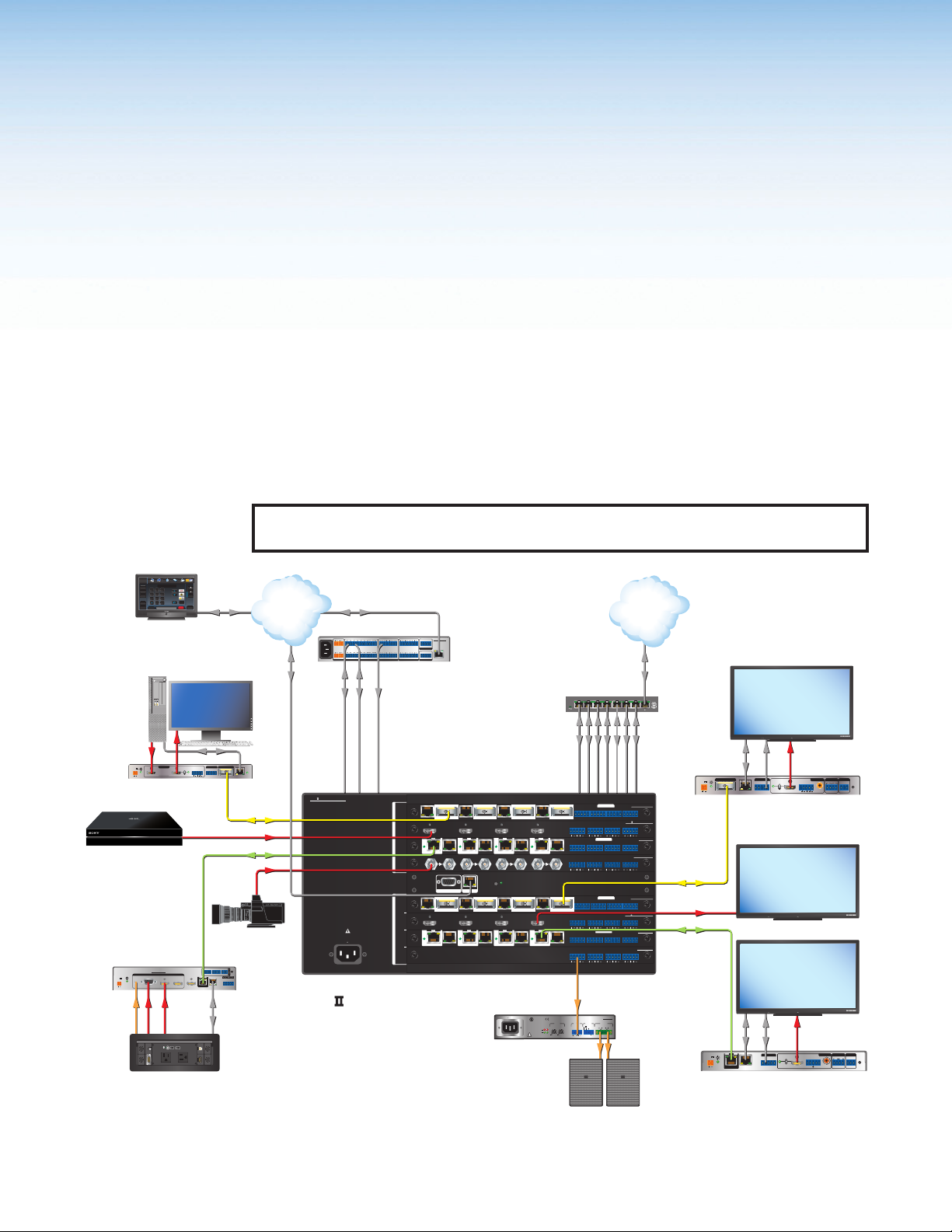
Figure 1. Typical XTP II CrossPoint 1600 Application
XTP II CrossPoint Series • Introduction 1
2
IR
IR
IR
RS-232
TxRx GTxRx
IR
RS-232
TxRx GTxRx
Audio
CLASS 2 WIRING
REMOTE
10V 50 mA
VOL/MUTE
STANDBY
RS-232
Tx Rx GTxRx
RS-232
Tx Rx GTxRx
OVER FIBER
OVER XTP
IR
AUDIOLOOP OUTINPUTLOOP OUTINPUTLOOP OUTINPUTLOOP OUTINPUT
OVER FIBER
OVER XTP
IR
RS-232
IR
IR
Tx Rx GTxRx
AUDIO
RS-232
IR
TxRx GTxRx
RS-232
IR
IR
Tx Rx GTxRx
AUDIO
RS-232
IR
TxRx GTxRx
AUDIO
XPA 1002
OUTPUT
2
1
Audio
XTP CP 4i FIBER 4K
RS-232
IR
Tx Rx GTxRx
XTP CP 4i HD 4K PLUS
XTP CP 4i 4K
RS-232
IR
TxRx GTxRx
XTP CP 4i 3G-SDI
LRLRLRLR
XTP CP 4o FIBER 4K
RS-232
IR
Tx Rx GTxRx
XTP CP 4o HD 4K PLUS
XTP CP 4o 4K
RS-232
IR
TxRx GTxRx
XTP CP 4o SA
Extron
SI 28
Surface Mount
Speakers
Ethernet IR HDMI
POWER
12V
--A MAX
SIG LINK
Fiber
HDMI
Shielded
Twisted Pair
POWER
12V
1.4 A MAX
XTP IN
OVER XTP
RS-232 RS-232IR
TxRx Tx Rx
G
LAN
Extron
XTP SFR HD 4K
XTP Fiber Receiver
MODEL 80
MODEL 80
Ethernet
SIG LINK
OVER XTP
RS-232 IR
XTP IN
LAN
FLAT PANEL
4K Display
OUTPUTS
AUDIOAUDIO
L
R12ON
OFF
HDMI
S/PDIF
FLAT PANEL
4K Display
FLAT PANEL
RS-232
HDMI
AUDIO
AUDIO
LR
ON
OFF
−+−+
HDMI
RxTx
Rx GTx
Extron
XTP SR HD 4
RELAYS
Display
OUTPUTS
RELAYS
1
S/PDIF
REMOTE
RESET
TxRx G
REMOTE
RS-232
2
RESET
TxRx G
Page 10

Product Description
The configurable and modular XTP II CrossPoint Series matrix switchers route video, audio,
bidirectional RS-232 and IR, and Ethernet signals in an integrated XTP system. The types of
signals routed depend on the input and output boards installed in the matrix switchers. The
number of supported input and output boards include the following:
• XTP II CrossPoint 1600 — Supports up to four input boards and four output boards in
a 5U high enclosure.
• XTP II CrossPoint 3200 — Supports up to eight input boards and eight output boards
in a 10U high enclosure.
• XTP II CrossPoint 6400 — Supports up to 16 input boards and 16 output boards in a
20U high enclsoure.
Input and output boards provide signal routing between sources and output devices. The
matrix switchers can also provide power to remote XTP devices over shielded twisted pair
cabling.
Input and Output Board Types
The input and output boards provide either local distribution of audio and video connections
to local sources and displays or signal extension to remote endpoints when using
XTP transmitters and receivers. Each board is hot-swappable for replacement without
interrupting signal routing. The following table describes available input and output boards
(see the Extron website for a current list of available XTP CrossPoint boards).
Input and Output Boards
Board Types Description
Twisted pair boards Input and output boards for XTP communication with Ethernet
extension and RS-232 and IR insertion over twisted pair cable.
4K twisted pair
boards
Fiber boards Input and output boards for XTP communication with Ethernet
HDMI boards Input and output boards for HDMI signals with analog stereo audio.
DMA boards Input boards with multi-channel audio downmixing to 2-channel
DVI Pro boards Input and output boards for HDCP-compliant DVI signals with
SDI boards Input boards for SDI signals.
VGA board Input board for universal analog video signals with analog stereo
Analog audio board Output board for analog stereo audio signals..
Each input and output is individually isolated and buffered. Any input can be switched to any
one or all outputs with virtually no crosstalk or signal noise between channels. Depending
on the board configuration, the matrix switcher can include 4 inputs and 4 outputs to one of
the following maximum sizes:
• XTP II CrossPoint 1600 — Supports up to 16 inputs and 16 outputs.
• XTP II CrossPoint 3200 — Supports up to 32 inputs and 32 outputs.
• XTP II CrossPoint 6400 — Supports up to 64 inputs and 64 outputs.
Input and output boards for 4K XTP communication with Ethernet
extension and RS-232 and IR insertion over twisted pair cable.
extension and RS-232 and IR insertion over fiber optic cable.
PCM stereo audio.
analog stereo audio.
audio.
XTP II CrossPoint Series • Introduction 2
Page 11

Twisted pair and 4K twisted pair boards
The input and output boards enable long distance transmission of AV signals between the
XTP II CrossPoint matrix switcher and remote twisted pair XTP transmitters and receivers.
The twisted pair cable carries the following signals up to 330 feet (100 meters) over a
shielded twisted pair cable:
• Digital video
• Digital audio
• Bidirectional RS-232 and IR commands
• Remote power
• Ethernet communication
• System communication
Each XTP connector is accompanied with an Ethernet extension port and bidirectional
RS-232 and IR insertion ports for simultaneous control of remote devices. The main
difference between the twisted pair and 4K twisted pair boards is as follows:
• Twisted pair boards are HDCP-compliant and support computer and video resolutions
up to 1920x1200, including 1080p @ 60 Hz with Deep Color and 2K.
• 4K twisted pair boards are HDCP 2.3 compliant and support video resolutions up to 4K.
See the board specifications at www.extron.com for further differences between the two
types boards.
Fiber boards
The input and output boards enable long-haul transmission of AV signals between the
XTP II CrossPoint matrix switcher and remote fiber XTP transmitters and receivers. The fiber
optic cable carries the following signals:
• Digital video
• Digital audio
• Bidirectional RS-232 and IR commands
• Ethernet communication
• System communication
Each XTP connector is accompanied with an Ethernet extension port and bidirectional
RS-232 and IR insertion ports for simultaneous control of remote devices. The boards are
HDCP-compliant and support video resolutions up to 4K.
Transmission distance depends on the model and fiber optic cable. The fiber optic cable is
categorized in two types of cable: multimode (MM) and singlemode (SM).
• Multimode — Transmits data up to 500 meters (1,640 feet) depending on the fiber
optic cable.
• Singlemode — Transmits data up to 10 km (6.2 miles).
NOTES:
• The multimode and singlemode boards are physically and functionally identical, with
the exception of the effective range of transmission. In this guide, any reference
applies to either transmission mode unless otherwise specified.
• Different modes are not compatible with each other.
• A color-coded sticker identifies the type of SFP module: orange for multimode and
yellow for singlemode.
XTP II CrossPoint Series • Introduction 3
Page 12

HDMI and DVI Pro boards
HDMI input and output boards support HDMI and separate analog stereo audio signals.
They provide the capability to connect local HDMI sources and output devices to XTP
Systems. Audio signals can be routed independently, including embedded HDMI audio.
• The XTP CP HDMI input and output boards are HDCP-compliant and support computer
and video resolutions up to 1920x1200, including 1080p/60 with Deep Color and 2K.
• The XTP II CP HD 4K PLUS input and output boards comply with HDCP 2.3 and
support video signals at resolutions up to 4K/60 at 4:4:4 chroma sampling.
• XTP II CP HD 8K input and output boards comply with HDCP 2.3, and support video
resolutions up to 8K/30 HDR video with 4:4:4 color sampling at data rates up to 40.1
Gbps.
DVI Pro input and output boards support DVI and separate analog stereo audio signals.
They provide the capability to connect local DVI sources and output devices to XTP
Systems. They are HDCP-compilant, and support computer and video resolutions up to
1920x1200, including 1080p/60 with Deep Color and 2K. Audio signals can be routed
independently.
DMA input boards
The DMA input boards provide multi-channel audio downmixing to 2-channel PCM stereo
audio for separable audio routing. They can decode and process licensed, branded digital
source formats from Dolby®1 and DTS®2, including Dolby TrueHD and DTS-HD Master
Audio™.
SDI boards
NOTE: 4K video can be routed only to boards that support that resolution.
The SDI boards provide four inputs for connection of 3G-SDI signals and 12G-SDI signals.
Each input features automatic equalization to optimize signal quality over long cable
runs, plus buffered loop-through with reclocking to support local monitors or additional
distribution needs.
• The XTP CP 4i 3G-SDI board supports signal rates up to 2.97 Gbps.
• The XTP CP 4i 12G-SDI input board supports 12G-SDI, 6G-SDI, 3G-SDI, and HD-SDI
video signal data rates up to 11.88 Gbps, and passes HDR, embedded audio. It
features buffered SDI and HDMI loop-through connections for local displays.
The boards also feature four balanced or unbalanced stereo audio inputs with audio
breakaway capability for switching distribution flexibility. Analog audio signals are digitized to
two-channel PCM digital audio for separate audio routing within the system.
1. Manufactured under license from Dolby Laboratories. Dolby, Dolby Audio, and the double-D symbol are
trademarks of Dolby Laboratories.
2. For DTS patents, see http://patents.dts.com. Manufactured under license from DTS, Inc. DTS, the Symbol,
DTS in combination with the Symbol, the DTS-HD logo, and DTS-HD Master Audio are registered trademarks
or trademarks of DTS, Inc. in the United States and/or other countries. © DTS, Inc. All Rights Reserved.
XTP II CrossPoint Series • Introduction 4
Page 13

VGA board
The VGA input board features universal video inputs that automatically detect incoming
RGBHV, HD component video, S-video, and composite video signals. It also features analog
stereo audio inputs for independent routing of audio signals.
The board switches high resolution video signals up to 1920x1200, including 1080p/60, and
stereo audio. Extron-exclusive SD Pro processing ensures compatibility with HDMI and
DVI-equipped displays, without the need for additional scalers.
Audio signals are digitized to two-channel PCM digital audio for separate audio routing
within the system. Audio breakaway provides the capability to separate audio signals from
corresponding video signals for switching to different destinations.
Audio board
The audio output board provides four analog stereo audio outputs for local connectivity to
XTP Systems. It provides balanced or unbalanced analog stereo audio output, and can be
used in audio breakaway applications.
Other XTP Devices
In an XTP System, XTP switchers, transmitters, or receivers connect to twisted pair, 4K
twisted pair, or fiber boards for long distance transmission of XTP signals. Each XTP
device can be configured locally, but in matrix applications, use SIS commands (see SIS
Configuration and Control on page44 or the XTP System Configuration Software (see
the XTP System Configuration Software Help File) through the matrix switcher.
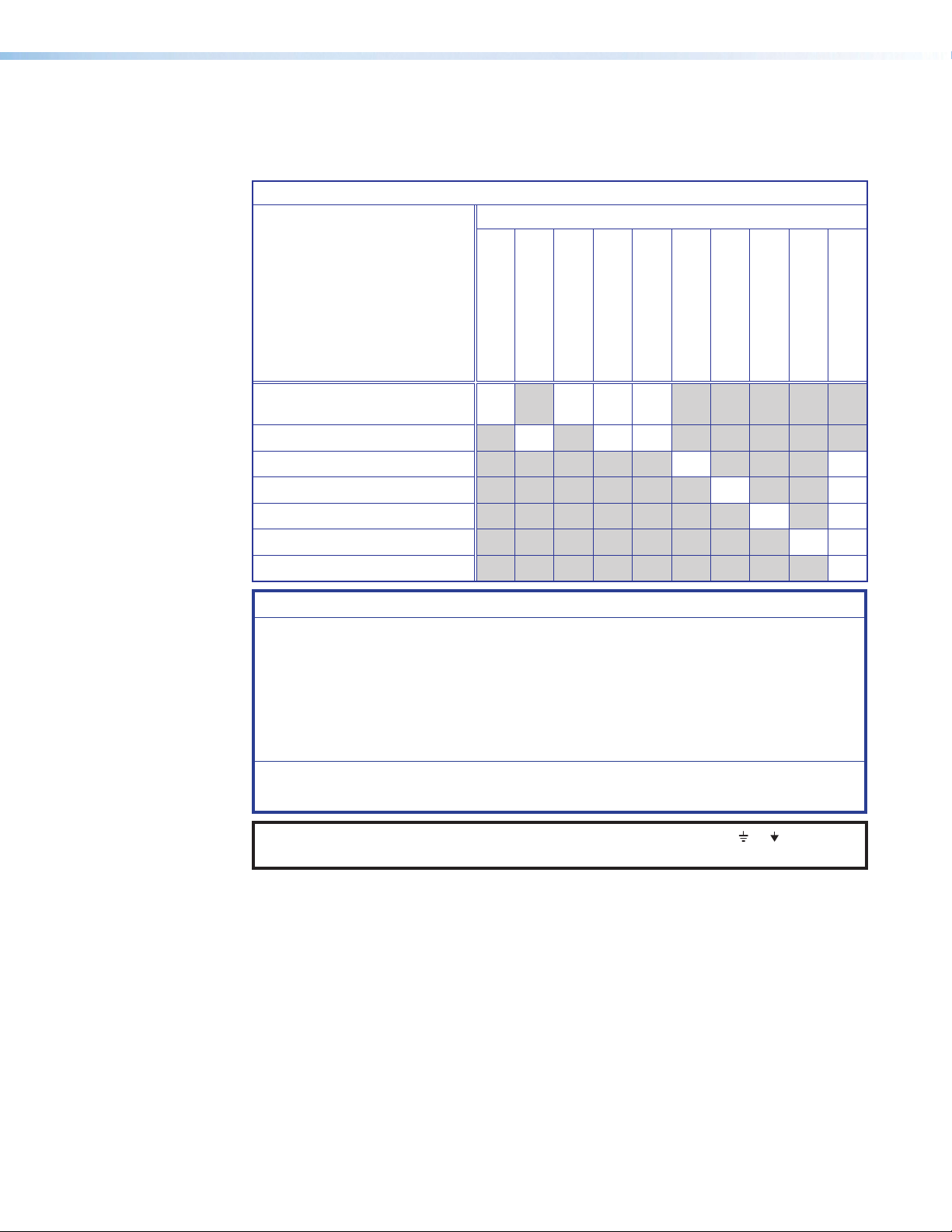
System Compatibility
XTP II CrossPoint series matrix switchers are compatible with other XTP devices, but the
maximum video resolution may be limited with different connected XTP models. See the
table below for maximum video resolutions and refresh rates for various XTP Systems.
Output
Analog 1920x1200
Non-4K
Digital
4K Fiber 2048x1080
4K Twisted
Input
Pair
4K PLUS 2048x1080
8K 2048x1080
Non-4K 4K Fiber 4K Twisted
Pair
@ 60 Hz
2048x1080
@ 60 Hz
@ 60 Hz
2048x1080
@ 60 Hz
@ 60 Hz
@ 60 Hz
1920x1200
@ 60 Hz
2048x1080
@ 60 Hz
4096x2160
@ 24 Hz
4096x2160
@ 24 Hz
4096x2160
@ 24 Hz
4096x2160
@ 24 Hz
1920x1200
@ 60 Hz
2048x1080
@ 60 Hz
4096x2160
@ 24 Hz
4096x2160
@ 30 Hz
4096x2160
@ 30 Hz
4096x2160
@ 30 Hz
4K Plus 8K
1920x1200
@ 60 Hz
2048x1080
@ 60 Hz
4096x2160
@ 24 Hz
4096x2160
@ 30 Hz
4096x2160
@ 60 Hz
4096x2160
@ 60 Hz
1920x1200
@ 60 Hz
2048x1080
@ 60 Hz
4096x2160
@ 24 Hz
4096x2160
@ 30 Hz
4096x2160
@ 60 Hz
7680x4320
@ 30 Hz
XTP II CrossPoint Series • Introduction 5
Page 14

Control Methods
To directly configure and control the matrix switchers, use one of the following methods:
• Front panel buttons (see Front Panel Operation on page28).
• SIS commands (see SIS Configuration and Control on page44)
• XTP System Configuration software (see the XTP System Configuration Software Help File)
• Internal web pages (see HTML Operation on page66)
NOTE: Do not connect a computer directly to a connected XTP device for configuration
when it is part of an XTP System.
For remote control of a matrix switcher, connect a host device to the matrix switcher. Host
devices include the following types of devices (see www.extron.com for a list of compatible
Extron control devices):
• A control system
• A PC
• An Extron remote control panel
NOTE: A front panel Configuration port connection and a rear panel Remote port
connection can both be active at the same time. If commands are sent to both
simultaneously, the command that reaches the processor first is handled first.
Features
Switching Features
• 50 Gbps digital backplane — Ensures switching and distribution of video signals
without degradation.
• SpeedSwitch Technology — Provides exceptional switching speed for HDCP-encrypted
content.
• Digital signal routing — Analog signals are digitized, sending a reliable, high quality
digital video signal to the output destination.
• QuickSwitch Front Panel Controller (QS-FPC) — Provides a discrete button for each
input and output, allowing for simple, intuitive operation.
XTP Interconnection Features
• XTP compatibility — Provides a flexible signal switching and distribution solution that is
completely integrated, ensuring reliable routing for multiple digital and analog formats.
• Ethernet extension — Reduces the amount of independent network drops required
within a system with centralized 10/100 Ethernet communication through Ethernet passthrough connectors.
• Remote power to XTP transmitters and receivers — Provides power to remote XTP
transmitters and receivers over the same STP cable that is used for sending AV signals.
This avoids the need for external power supplies at remote endpoints.
XTP II CrossPoint Series • Introduction 6
Page 15

Video Features
• Computer and video resolutions up to 8K — Exceeds the data-rate requirements
• HDMI 2.1, 2.0, 1.4, or 1.3 compatibility (dependent on connected devices) —
• HDCP compliant up to HDCP 2.3 (dependent on connected devices) — Ensures
• SD Pro processing — Deinterlaces 480i and 576i signals for compatibility with HDMI
Audio Features
• Audio input gain and attenuation — Allows the level of gain or attenuation to be set,
• Audio output volume adjustment and muting capabilities
• Audio breakaway — Separates an embedded audio signal from the corresponding
of the highest resolution video formats, including 8K/30 with 4:4:4 chroma sampling at
data rates up to 40.1 Gbps.
Supports HDMI specification features, including data rates up to 40.1 Gbps, Deep Color
up to 12-bit, 3D formats, Lip Sync, and HD lossless audio formats.
display of content-protected media and interoperability with other HDCP-compliant
devices.
and DVI-equipped displays, without the need for additional scalers.
eliminating noticeable volume differences when switching between sources.
video signal within the matrix switcher, allowing the audio and video signals from one
source to be switched to different destinations.
Control Features
• Front panel configuration port — Enables easy configuration without having to
access rear panel of the matrix switcher.
• Optional remote control — Provides the flexibility to control the matrix switcher from
a remote location.
• Serial port insertion from the Ethernet control port — Provides comprehensive
control of connected XTP devices and attached devices without needing additional
cabling.
General Features
• Flexible input and output sizes — Matches a wide variety of small to large-sized
installations. Sizes depend on the matrix switcher model.
• Wide selection of input and output boards — Provide integration for a variety of
signal types and formats, ensuring system customization appropriate for a wide range
of applications.
• Modular, field-upgradeable and hot-swappable design — Provides substantial
flexibility, expandability, and affordability. Additional input and output boards may
be added at any time for quick and easy upgrade or expansion. Hot-swappable
components allow the user to replace an input and output board at any time without the
need to power down the matrix switcher.
• EDID Minder — Automatically manages EDID communication between connected
devices, ensuring that all sources power up properly and reliably output content for
display.
• Key Minder — Continuously verifies HDCP compliance for quick, reliable switching.
Authenticates and maintains continuous HDCP encryption between input and output
devices to ensure quick and reliable switching in professional AV environments, while
enabling simultaneous distribution of a single source signal to one or more displays.
XTP II CrossPoint Series • Introduction 7
Page 16

• HDCP authentication and signal confirmation via RS-232 or Ethernet —
Provides real-time verification of HDCP status for each digital video input and output.
• HDCP Visual Confirmation — Provides a green signal when encrypted content is sent
to a non-compliant display, providing immediate visual confirmation that protected content
cannot be viewed on the display.
• +5 VDC, 250 mA power — Provides power through the digital output of a board
eliminates the need of a separate power supply for the connected peripheral device.
• Four power connections provide +12 VDC, 125 mA power for active HDMI cables
— XTP II CP 4i HD 8K input board only
• Automatic cable equalization — Optimizes signal performance for all incoming digital
signals up to 100 feet (30 m) when used with Extron HDMI or DVI Pro cables.
• Automatic output reclocking — Reshapes and restores timing of digital video signals
at each output, eliminating high frequency jitter to ensure reliable transmission over long
cables.
• Ethernet monitoring and control — Provides proactive monitoring and system
management over a LAN, WAN, or the Internet, using standard TCP/IP protocols.
Ethernet control provides for remote selection of input and output ties, adjustment and
control of audio input and output levels, and advanced system diagnostics.
• Tri-color, backlit buttons — Illuminate red, green, or amber, depending on function, for
ease of use in low-light environments.
• Global presets — Save and recall input and output configurations either from the front
panel, serial, or Ethernet control.
• View I/O mode — Displays which inputs and outputs are actively connected.
• Front panel security lockout — Prevents unauthorized use in non-secure
environments.
• JITC Certified — Assures interoperability and information for use in government
applications and other mission-critical environments.
• Rack-mountable enclosure — Allows for the full rack width metal enclosure to fit in 5U,
10U, or 20U rack spaces.
• Internal universal power supply (XTP II CrossPoint 1600 and XTP II CrossPoint 3200)
— Provides worldwide power compatibility with the 100-240 VAC, 50/60 Hz international
power supply.
• Primary and redundant power supplies — Provides power reliability for
continuous, mission-critical applications (redundant power supplies are optional
for the XTP II CrossPoint 1600, standard for the XTP II CrossPoint 3200 and
XTP II CrossPoint 6400).
• Highly reliable, energy-efficient internal universal power supply
(XTP II CrossPoint 6400) — Provides worldwide power compatibility with the single phase
200-240 VAC, 50/60 Hz international power supply.
NOTE: In North America, the XTP II CrossPoint 6400 plugs into a standard 220 V
power outlet. In other regions, it must be wired into a 200-240 VAC junction box.
In either case, the outlet or junction box must be installed near the equipment and
be easily accessible.
XTP II CrossPoint Series • Introduction 8
Page 17

• Permanent, rechargeable battery — Tracks time of day when power is disconnected.
WARNING: There is a danger of explosion if the battery is incorrectly
replaced. Replace it only with the same or equivalent type recommended by
the manufacturer. Dispose of used batteries according to the instructions of the
manufacturer.
AVERTISSEMENT : Si la pile est mal remplacée, il y a un risque d’explosion.
Remplacez la batterie seulement avec le même type ou un type similaire de pile,
recommandé par le fabricant. Débarrassez-vous des piles utilisées selon les
instructions du fabricant.
ATTENTION:
• Non-Extron personnel must not attempt to remove the battery. Doing so voids
the warranty.
• Du personnel ne faisant pas partie d’Extron ne doit pas essayer de retirer la
batterie. Cela annulerait la garantie.
XTP II CrossPoint Series • Introduction 9
Page 18

Installation
This section details the installation and configuration of the XTP II CrossPoint Series matrix
switchers. Topics in this section include the following:
• Installation Overview
• Rear Panel Features
• Input and Output Board Features
• Connection Details
Installation Overview
The following list describes the basic installation procedure to set up an XTP II CrossPoint
Series matrix switcher.
1. Install input and output boards (see Input board slots and Output board slots on
page12).
2. If desired, replace button labels (see Installing Labels in the Buttons on page90).
3. Mount the matrix switcher (see Mounting the Matrix Switcher on page80).
4. Connect devices to the input and output boards (see Input and Output Board
Connectors on page13).
NOTE: The types and number of connectors available depend on the boards
installed in the matrix switcher.
5. Connect control devices to the matrix switcher through the following connectors.
• Front panel USB configuration connector (see Front Panel Features on
page26).
• Rear panel RS-232 and RS-422 connector (see Remote RS-232 and RS-422
connector on page 12).
• Rear panel Ethernet LAN connector (see Ethernet LAN connector on page 12).
NOTE: For an Ethernet connection, obtain IP setting information from the local
network administrator.
6. Connect power (see Power connector on page12).
XTP II CrossPoint Series • Installation 10
Page 19
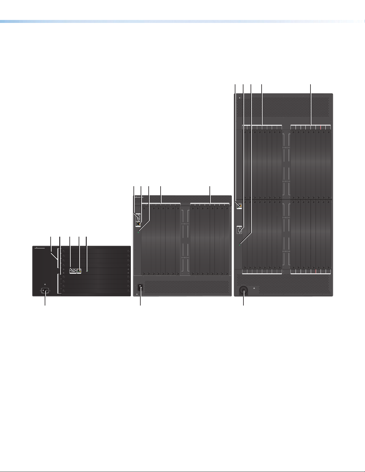
Rear Panel Features
X
The XTP II CrossPoint matrix switchers include the same rear panel features. However, the
XTP II CrossPoint 1600 includes horizontal slots for input and output boards instead of
vertical slots. Each model also contains a different number of available board slots.
DCEA B
XTP II CROSSPOINT 6400
INPUTS
1-45-8 9-12 13-16
XTP CP 4i 4K
IR
RS-232
IR
RS-232
IR
OVER XTP
RS-232
IR
RS-232
SIG LINK
PWR
SIG LINK
PWR
SIG LINK
CDEA B
XTP CROSSPOINT 3200
INPUTS
1-45-8 9-12 13-16
REMOTE
RS-232/422
LAN
ABCDE
XTP CROSSPOINT 1600
DISCONNECT POWER
CORD BEFORE
100-240V
1−4
5−8
INPUTS
9−12
13−16
1−4
5−8
OUTPUTS
9−12
SERVICING
12.0A MAX
13−16
50-60Hz
RS-232/422
REMOTELAN
RESET
RESET
12A MAX
50-60Hz
100-240V
DISCONNECT POWER
CORD BEFORE
SERVICING
17-20 21-24 25-28 29-32 1-45-8 9-12 13-16
1591317212529
481216 20 24 28 32
O
I
U
N
T
P
P
U
U
T
T
S
S
29
15913172125
481216 20 24 28 32
OUTPUTS
17-20 21-24 25-28 29-32
PWR
SIG LINK
PWR
INPUTS
LAN
REMOTE
RS-232/422
RESET
33-36 37-40 41-44 45-48 49-52 53-56 57-60 61-64 33-36 37-40 41-44 45-48 49-52 53-56 57-60 61-64
17-20 21-24 25-28 29-32
XTP CP 4i 4K
XTP CP 4i 4K
XTP CP 4i 4K
XTP CP 4i 4K
IR
IR
IR
IR
XTP II CP 4i 4K PLUS
XTP II CP 4i 4K PLUS
TxRx GTxRx
TxRx GTxRx
TxRx GTxRx
RS-232
RS-232
RS-232
IR
IR
IR
TxRx GTxRx
TxRx GTxRx
TxRx GTxRx
RS-232
RS-232
RS-232
IR
IR
IR
OVER XTP
OVER XTP
OVER XTP
TxRx GTxRx
TxRx GTxRx
TxRx GTxRx
RS-232
RS-232
RS-232
IR
IR
IR
TxRx GTxRx
TxRx GTxRx
TxRx GTxRx
RS-232
RS-232
RS-232
LAN
LAN
LAN
XTP IN
XTP IN
XTP IN
SIG LINK
SIG LINK
SIG LINK
PWR
PWR
PWR
LAN
LAN
LAN
XTP IN
XTP IN
XTP IN
SIG LINK
SIG LINK
SIG LINK
PWR
PWR
PWR
LAN
LAN
LAN
XTP IN
XTP IN
XTP IN
SIG LINK
SIG LINK
SIG LINK
PWR
PWR
PWR
LAN
LAN
LAN
XTP IN
XTP IN
XTP IN
SIG LINK
SIG LINK
SIG LINK
PWR
PWR
PWR
INPUTS
INPUTS
INPUTS
DISCONNECT POWER
BEFORE SERVICING
220-240V
50-60 Hz
XX.XA MAX
XTP II CP 4i 4K PLUS
TxRx GTxRx
TxRx GTxRx
RS-232
IR
TxRx GTxRx
TxRx GTxRx
RS-232
AUDIO
AUDIO
AUDIO
IR
OVER XTP
TxRx GTxRx
TxRx GTxRx
RS-232
IR
LRLRLR LR
LRLRLR LR
LRLRLR LR
TxRx GTxRx
TxRx GTxRx
RS-232
LAN
LAN
XTP IN
XTP IN
SIG LINK
PWR
LAN
LAN
XTP IN
XTP IN
SIG LINK
PWR
LAN
LAN
XTP IN
XTP IN
SIG LINK
PWR
LAN
LAN
XTP IN
XTP IN
SIG LINK
PWR
INPUTS
INPUTS
INPUTS
INPUTS
XTP CP 4i 4K
IR
RS-232
IR
RS-232
IR
OVER XTP
RS-232
IR
RS-232
SIG LINK
PWR
SIGLINK
PWR
SIGLINK
PWR
SIGLINK
PWR
INPUTS
INPUTS OUTPUTS
1591317212529
481216 20 24 28 32
15913172125
481216 20 24 28 32
TxRx GTxRx
TxRx GTxRx
3337 41 45 49 53 57 61
TxRx GTxRx
3640 44 48 52 56 60 64
TxRx GTxRx
LAN
XTP IN
LAN
XTP IN
LAN
3337 41 45 49 53 57
3640 44 48 52 56 60 64
XTP IN
LAN
XTP IN
O
I
U
N
T
P
P
U
U
T
T
S
S
29
O
I
U
N
T
P
P
U
U
T
T
S
S
61
1-45-8 9-12 13-16
XTP CP 4o 4K
XTP CP 4o 4K
XTP CP 4o 4K
IR
IR
TxRx GTxRx
TxRx GTxRx
RS-232
RS-232
IR
IR
TxRx GTxRx
TxRx GTxRx
RS-232
RS-232
IR
IR
OVER XTP
OVER XTP
OVER XTP
TxRx GTxRx
TxRx GTxRx
RS-232
RS-232
IR
IR
TxRx GTxRx
TxRx GTxRx
RS-232
RS-232
LAN
LAN
XTP OUT
XTP OUT
SIG LINK
SIG LINK
SIG LINK
PWR
PWR
LAN
LAN
XTP OUT
XTP OUT
SIGLINK
SIGLINK
SIGLINK
PWR
PWR
LAN
LAN
XTP OUT
XTP OUT
SIGLINK
SIGLINK
SIGLINK
PWR
PWR
LAN
LAN
XTP OUT
XTP OUT
SIGLINK
SIGLINK
SIGLINK
PWR
PWR
OUTPUTS
OUTPUTS
OUTPUTS
IR
TxRx GTxRx
RS-232
IR
TxRx GTxRx
RS-232
IR
TxRx GTxRx
RS-232
IR
TxRx GTxRx
RS-232
LAN
XTP OUT
PWR
LAN
XTP OUT
PWR
LAN
XTP OUT
PWR
LAN
XTP OUT
PWR
OUTPUTS
17-20 21-24 25-28 29-32
XTP CP 4o 4K
IR
XTP II CP 4o 4K PLUS
TxRx GTxRx
RS-232
IR
TxRx GTxRx
RS-232
AUDIO
IR
OVER XTP
TxRx GTxRx
RS-232
IR
TxRx GTxRx
RS-232
LAN
XTP OUT
SIG LINK
PWR
LAN
XTP OUT
SIGLINK
PWR
LAN
XTP OUT
SIGLINK
PWR
LAN
XTP OUT
SIGLINK
PWR
OUTPUTS
OUTPUTS
LRLRLR LR
XTP CP 4o SA
XTP CP 4o SA
XTP II CP 4o 4K PLUS
AUDIO
AUDIO
AUDIO
LRLR LR LR
LRLR LR LR
LRLRLR LR
OUTPUTS
OUTPUTS
OUTPUTS
F
TP II CrossPoint 1600
F
XTP II CrossPoint 3200 XTP II CrossPoint 6400
Input board slots (see the next page)
A
Output board slots
B
Remote RS-232 and RS-422 connector
C
Ethernet LAN connector
D
Reset button and LED
E
Power connector
F
F
Figure 2. XTP II CrossPoint Matrix Switcher Rear Panels
XTP II CrossPoint Series • Installation 11
Page 20
Input board slots — Install input boards or blank plates in the available slots in any
L6-20R
G: Ground
A
order or arrangement. Note the input numbers associated with each slot. The boards
align vertically except on the XTP II CrossPoint 1600 where they align horizontally.
Ensure a board or blank plate is installed in every slot.
Output board slots — Install output boards or blank plates in the available slots in any
B
order or arrangement. Note the output numbers associated with each slot. The boards
align vertically except on the XTP II CrossPoint 1600 where they align horizontally.
Ensure a board or blank plate is installed in every slot.
Remote RS-232 and RS-422 connector — Connect a host device to the 9-pin D
C
connector for serial RS-232 or RS-422 control of the matrix switcher (see Remote
RS-232 and RS-422 Connection on page 19 for wiring details).
NOTE: The matrix switcher supports the RS-232 or RS-422 serial communication
protocol, and operates at 9600, 19200, 38400, or 115200 baud rates.
To connect an MKP 2000 or MKP 3000 remote control panel, see to the MKP 2000
Remote Control Panel User Guide or the MKP 3000 User Guide for details.
Ethernet LAN connector — Connect a computer network to the RJ-45 connector to
D
control the matrix switcher remotely through Ethernet. Use a patch cable to connect to
a switch, hub, or router. The LAN connector includes the following LED indicators:
• Activity LED indicator — Blinks when the matrix switcher communicates with the
connected device.
• Link LED indicator — Lights when the matrix switcher is connected to an
Ethernet LAN.
Reset button and LED — Press the Reset button to activate different reset modes
E
(see Reset Modes on page41).
Power connector — Connect a power supply to the AC power connector.
F
• Default AC power — Connect a 100 VAC to 240 VAC, 50-60 Hz
power source to this connector with a standard IEC power cord to
this connector.
• Attached AC power (XTP II CrossPoint 6400 only) —
• North America — Connect the power cord into a NEMA L6-20
North America
X
G
Y
X: Hot Y: Hot
220 VAC, 60 Hz power outlet.
• Other regions — Have a licensed electrician install a 200-240 VAC power
connector. Then, connect the power cord into a 200-240 VAC,
50-60 Hz power outlet. Ensure the wiring is in accordance with electrical codes.
ATTENTION:
• The outlet or junction box must be installed near the equipment and be
easily accessible.
• La prise de courant ou la boîte de jonction doivent être installées près
du dispositif et être facilement accessibles.
• The installation location must provide short circuit and overcurrent
protection, to a minimum of 20 A.
• Le lieu d’installation doit disposer d’une protection contre les courts-
circuits et la surtension de 20 A minimum.
• Do NOT use an extension cord.
• Ne PAS utiliser de rallonge électrique.
XTP II CrossPoint Series • Installation 12
Page 21
Input and Output Board Connectors
Each input and output board supports up to four inputs or outputs. See the table below for
signal types included on the input and output boards.
Board Signal Types
Signal Type
Board Types
Twisted pair and
4K twisted pair boards
Fiber boards • • •
HDMI and DMA boards • •
DVI Pro boards • •
SDI board • •
VGA board • •
Analog audio board •
ATTENTION:
• Use electrostatic discharge (ESD) precautions (be electrically grounded) when
making connections. Electrostatic discharge can damage equipment, even if you
cannot feel, see, or hear it.
• Prenez des précautions contre les décharges électrostatiques (ESD) (soyez
électriquement relié à la terre) lorsque vous effectuez des connexions. Les
décharges électrostatiques peuvent endommager l’équipement, même si vous ne
pouvez pas le sentir, le voir ou l’entendre.
• Remove system power before making all connections.
• Débranchez l’alimentation du système avant de faire n’importe quelle connexion.
XTP Twisted Pair
XTP Fiber
Remote Power
RS-232 Inserts
• • • •
Dedicated UARTs
HDMI
DVI Pro
3G/HD-SDI/SDI
Analog Video
Analog Audio
NOTE: Audio ground pins on the input and output boards are labeled or . The wiring
and function are the same, whichever way the board is labeled.
XTP II CrossPoint Series • Installation 13
Page 22
XTP Interconnection
XTP IN
PW
SIG LINK
XTP OUT
PW
SIG LINK
SignalLink
XTP interconnection features include XTP twisted pair, XTP fiber, pass-through LAN, and RS-232
and IR Over XTP connectors on twisted pair, 4K twisted pair, and fiber boards.
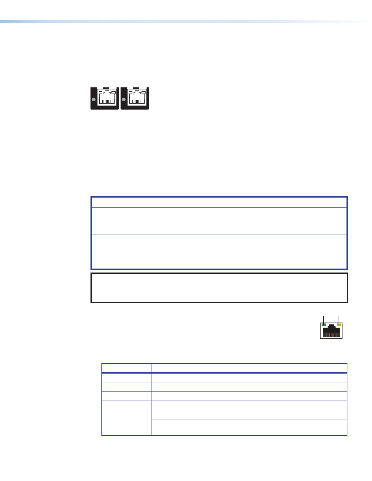
XTP twisted pair input and output connectors
R
R
Figure 3. XTP Twisted Pair Input Connector (Left) and XTP Twisted Pair Output
Connector (Right)
Connect an XTP twisted pair transmitter to an XTP twisted pair input connector or an XTP twisted
pair receiver to an XTP twisted pair output connector (see Twisted Pair Cable Termination and
Recommendations for XTP Communication on page19) to the RJ-45 connector. The cable
carries the following signals:
• Digital video
• Digital audio
• Bidirectional RS-232 and IR commands
• Remote power
• Ethernet communication
• System communication
ATTENTION:
• Do not connect this connector to a computer data or telecommunications network.
• Ne connectez pas ce connecteur à un réseau de données informatiques ou à un réseau
de télécommunications.
• XTP remote power is intended for indoor use only. No part of the network that uses XTP
remote power should be routed outdoors.
• XTP à distance est destiné à une utilisation en intérieur seulement. Aucune partie du
réseau qui utilise l’alimentation XTP à distance ne peut être routée en extérieur.
NOTE: To enable XTP remote power from a matrix switcher, use one of the following methods:
• SIS commands (see the Enable/Disable XTP Remote Power commands on page 57)
• XTP System Configuration Software (see the XTP System Configuration Software Help file)
Each connector also includes LEDs for signal, link, and power status:
• Signal LED indicator — Lights when the either the input board receives an XTP
signal or the output board sends an XTP signal.
• Link LED indicator — Lights when XTP devices are connected and
communication is established.
• XTP power LED indicator — Lights when the board provides XTP remote power to the
connected XTP device.
LED state Indication
Off Endpoint does not support remote power
Green Endpoint is being powered
Amber Power available but port is currently disabled
Amber – blinking Power unavailable but port is enabled
Problem with RJ-45 connection
Red – blinking
For DTP products that support XTP mode: this LED state indicates
that a DTP port (with XTP mode enabled) is connected to the XTP port.
XTP II CrossPoint Series • Installation 14
Page 23
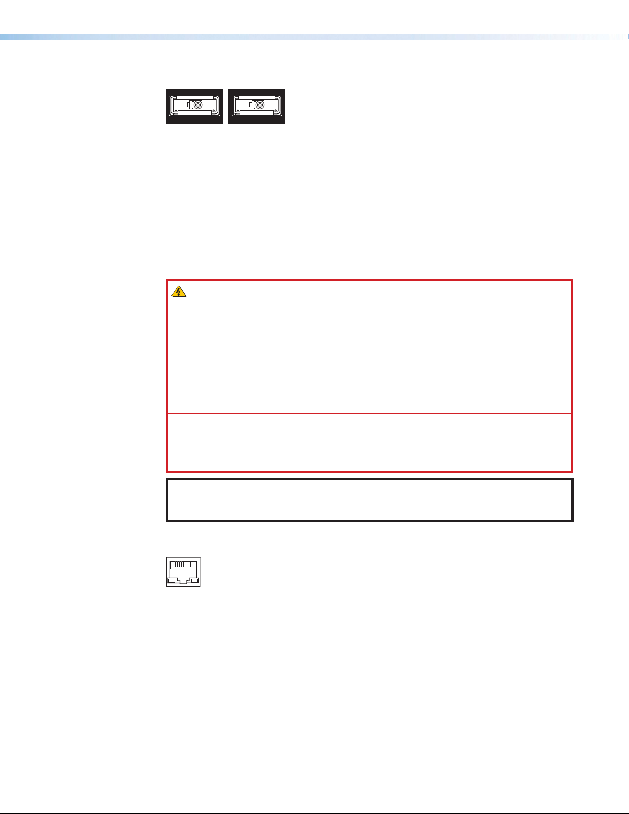
XTP fiber input and output connectors
GL
XTP OUT
GL
XTP IN
LAN
SI
SI
INK
INK
Figure 4. XTP Fiber Input Connector (Left) and XTP Fiber Output Connector
(Right)
Connect an XTP fiber transmitter to an XTP fiber input connector or an XTP fiber receiver to
an XTP fiber output connector. The cable carries the following signals:
• Digital video
• Digital audio
• Bidirectional RS-232 and IR commands
• Ethernet communication
• System communication
WARNING: Potential risk of severe injury. The device outputs continuous
invisible light, which may be harmful to the eyes; use with caution.
AVERTISSEMENT : Risque potentiel de blessure grave ou de mort. Le dispositif émet
une lumière invisible en continu qui peut être dangereux pour les yeux, à utiliser avec
précaution.
• Do not look into the rear panel fiber optic cable connectors or into the fiber optic
cables themselves.
• Ne regardez pas dans les connecteurs de câble fibre optique sur le panneau arrière
ou dans les câbles fibre optique eux-mêmes.
• Plug the attached dust caps into the optical transceivers when the fiber cable is
unplugged.
• Branchez les protections contre la poussière dans l’ensemble émetteur/récepteur
lorsque le câble fibre optique est débranché.
NOTE: Ensure the proper fiber optic cable is used. Typically, singlemode fiber optic
cable has a yellow jacket and multimode fiber optic cable has an orange or aqua
jacket.
Pass-through LAN connectors
Figure 5. Pass-Through LAN Connector
Connect a control device or a device to control to a pass-through LAN connector for
10/100BASE-T Ethernet communication (see Twisted Pair Cable Termination for
Ethernet Communication on page21).
XTP II CrossPoint Series • Installation 15
Page 24
RS-232 and IR Over XTP or RS-232 Over Fiber connector
Tx Rx GTxRx
Tx Rx GTxRx
DVI-D
The RS-232 and IR Over XTP and RS-232 Over Fiber connectors are functinoally the same.
The connector name depends on the type of XTP interconnection.
OVER XTP
RS-232
IR
Figure 6. RS-232 and IR Over XTP (Left) and RS-232 Over Fiber (Right)
• RS-232 Over XTP or RS-232 Over Fiber connector — To pass bidirectional serial
signals between XTP devices, connect a control device or device to control to the
5-pole captive screw connector. The connector includes only the 2 poles labeled
“RS-232” and shares the ground pole with the IR poles.
• IR Over XTP or IR Over Fiber connector — To transmit and receive IR signals (up
to 56 kHz), connect a control device or device to control to the 5-pole captive screw
connector. This connector includes only the 2 poles labed “IR” and shares the ground
pole with the RS-232 poles.
NOTE: RS-232 and IR data can be transmitted or received simultaneously (see RS-232
and IR Over XTP Communication on page22 for wiring details).
Input Connections
OVER FIBER
RS-232
Connectors
IR
Excluding XTP interconnection, input boards connect local video and audio sources directly
to inputs on the matrix switcher. The types of connectors available depend on the board,
but may include HDMI, DVI, SDI, analog video, or analog audio connectors.
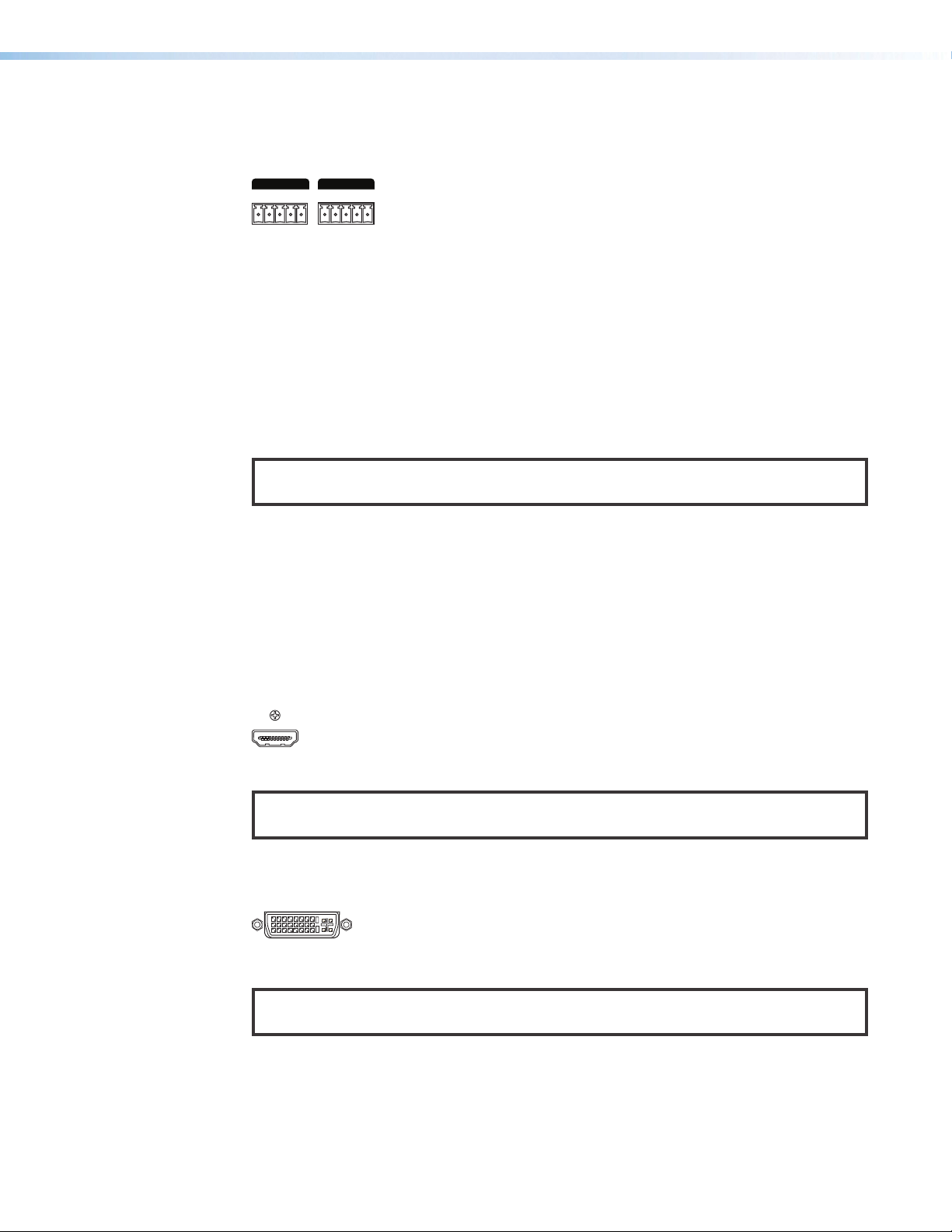
HDMI input connectors
Connect a digital video source device to an HDMI input connector. The connector accepts
HDMI, DVI (with an appropriate adapter), or dual mode DisplayPort video sources.
Figure 7. HDMI Input Connector
NOTE: Use an Extron LockIt Cable Lacing Bracket to secure an HDMI cable to the
HDMI connector (see HDMI Connection on page24).
DVI input connectors
Connect a digital video source to a DVI Pro input connector.
Figure 8. DVI Pro Input Connector
NOTE: Although the DVI Pro boards use DVI-I connectors, the matrix switcher handles
only DVI-D (digital) video.
XTP II CrossPoint Series • Installation 16
Page 25

SDI input connectors
LOOP OUTINPUT
LR
Each SDI connector is accompanied with a local loop out connector.
• SDI Input connector — Connect a digital video source to a BNC input connector.
The connector accepts 3G-SDI, HD-SDI, or SDI video and embedded digital audio.
Additionally, the XTP CP 4i 12G-SDI board accepts 12G-SDI signals.
• SDI Loop Out connector — Connect a local digital display to the BNC loop out
connector of the associated input signal for a buffered loop-through.
NOTE: SDI boards ship with 75 ohm terminators on the Loop Out connectors.
Extron recommends leaving these installed when the loop out is not used.
Figure 9. SDI Input and SDI Loop Output Connector
Analog video input connectors
Connect a computer video source to the 15-pin HD connector (see Analog Video
Connection on page23 for wiring details). It accepts RGB (RGBHV, RGBs, and RGsB),
component, S-video, or composite video signals.
Figure 10. 15-Pin HD Input Connector
Analog audio input connectors
Connect a balanced or unbalanced, stereo analog audio source to the 5-pole captive screw
connector (see Analog Audio Connection on page25 for wiring details).
Figure 11. Analog audio input connector
By default, the matrix switcher prioritizes embedded digital audio when both digital and
analog audio are present. To send analog audio, use one of the following methods:
• SIS commands:
• For input cards, see the Audio routing selection SIS command on page 52.
• For endpoints, see the Audio routing selection for endpoints SIS command.
• The XTP System Configuration Software (see the XTP System Configuration Software
Help file)
XTP II CrossPoint Series • Installation 17
Page 26
Output Connection
DVI-D
LR
1 (PRI)2 (SEC)
AT
Excluding XTP interconnection, output boards connect local video and audio output devices
directly to outputs on the matrix switcher. The types of connectors available depends on the
board, but may include HDMI, DVI, or analog audio connectors.
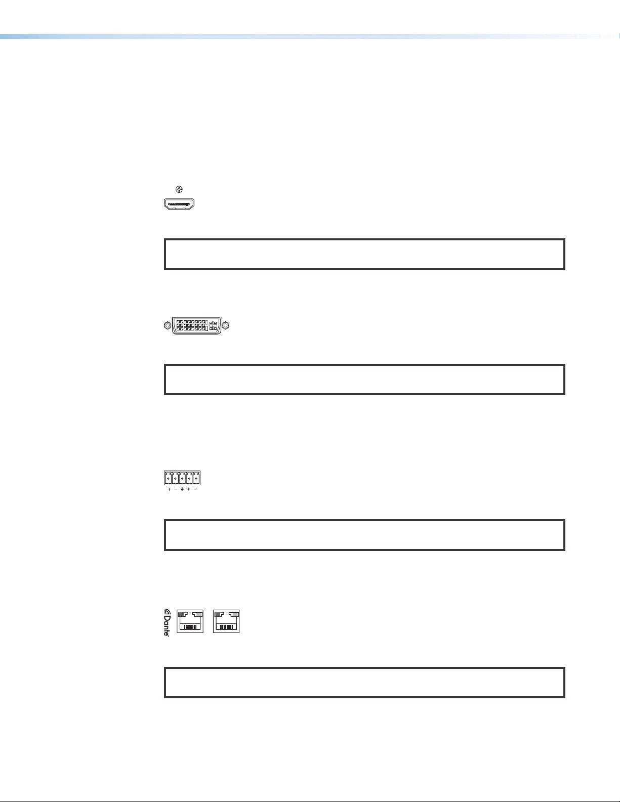
HDMI output connectors
Connect a display device to the female HDMI connector. It sends HDMI and DVI (with an
appropriate adapter) signals.
Figure 12. HDMI Output Connector
NOTE: Use an Extron LockIt Cable Lacing Bracket to secure an HDMI cable to the
HDMI connector (see HDMI Connection on page24).
DVI Pro output connectors
Connect a display device to the female DVI-I connector.
Figure 13. DVI Pro Output Connector
NOTE: Although the DVI Pro boards use DVI-I connectors, the matrix switchers handle
only DVI-D (digital) video.
Analog audio output connectors
Connect a balanced or unbalanced, stereo or mono analog audio device to the 3.5 mm,
5-pole captive screw connector (see Analog Audio Connection on page25 for wiring
details).
Figure 14. Analog Audio Output Connector
NOTE: If the input audio is 2-channel LPCM embedded audio on an HDMI input signal,
the audio signal is extracted and converted to a stereo analog signal.
Dante digital audio output connectors
Connect a Dante-enabled audio processing device to a Dante digital audio transport (AT)
LAN connector.
Figure 15. Dante Digital Audio Output Connector
NOTE: The Dante Controller software (available at www.extron.com) is required for
configuration of the AT ports.
XTP II CrossPoint Series • Installation 18
Page 27
Connection Details
1
5
6
9
Connector
Inser
Pins:
Pin
1
2
3
4
5
6
7
8
Wire color
White-green
Green
White-orange
Blue
White-blue
Orange
White-brown
Brown
Wire color
T568A T568B
White-orange
Orange
White-green
Blue
White-blue
Green
White-brown
Brown
For connectors that require additional wiring details or recommendations, see the following
sections pertaining to the type or connection.
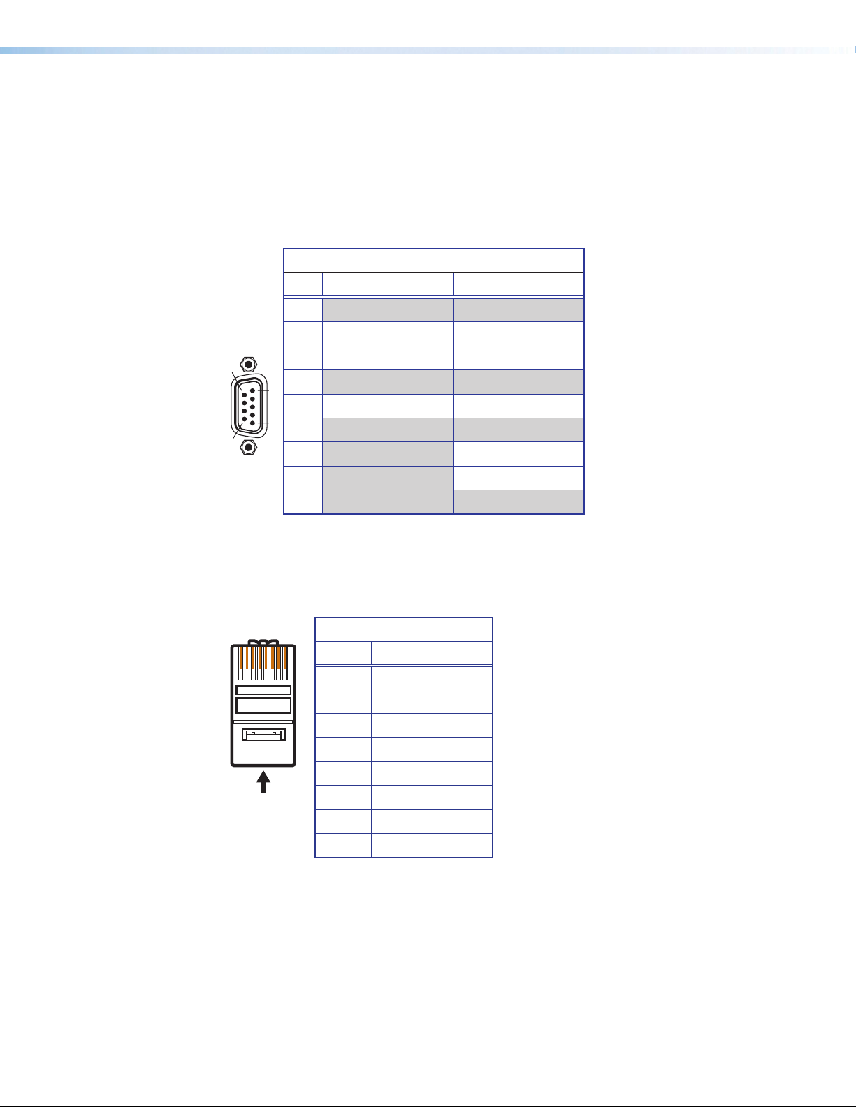
Remote RS-232 and RS-422 Connection
Wire the 9-pin D connector for either RS-232 or RS-422 communication. See the following
table for pin assignment details.
Remote RS-232 and RS-422 Pinout Table
Pin RS-232 RS-422
1
2 Tx Tx-
3 Rx Rx-
4
5 Gnd Gnd
6
7 Rx+
8 Tx+
9
Twisted Pair Cable Termination and Recommendations for XTP Communication
Use the following pin configurations for twisted pair cables used for XTP communication.
TIA/EIA-T568B
Pin Wire Color
1 White-orange
2 Orange
3 White-green
4 Blue
5 White-blue
6 Green
7 White-brown
8 Brown
XTP II CrossPoint Series • Installation 19
12345678
Pair Wires
RJ-45
t Twisted
Page 28

Supported cables
The XTP connectors are compatible with shielded twisted pair (F/UTP, SF/UTP, and S/FTP)
and unshielded twisted pair (U/UTP) cables.
ATTENTION:
• Do not use Extron UTP23SF-4 Enhanced Skew-Free AV UTP cable or STP201
cable to link the XTP products.
• N’utilisez pas le câble AV Skew-Free UTP version améliorée UTP23SF d’Extron ou
le câble STP201 pour relier les produits XTP.
• To ensure FCC Class A and CE compliance, STP cables and STP connectors are
required.
• Afin de s’assurer de la compatibilité entre FCC Classe A et CE, les câbles STP et
les connecteurs STP sont nécessaires.
Cable recommendations
Extron recommends using the following practices for XTP communication to achieve full
transmission distances up to 330 feet (100 meters) and reduce transmission errors.
• Use the following Extron XTP DTP 24 SF/UTP cables and connectors for the best
performance:
• XTP DTP 24/1000 Non-Plenum 1000’ (305 m) spool 22-236-03
• XTP DTP 24P/1000 Plenum 1000’ (305 m) spool 22-235-03
• XTP DTP 24 Plug Package of 10 101-005-02
• If not using XTP DTP 24 cable, at a minimum, Extron recommends 24 AWG, solid
conductor, STP cable with a minimum bandwidth of 400 MHz.
• Terminate cables with shielded connectors to the TIA/EIA-T568B standard.
• Limit the use of more than two pass-through points, which may include patch points,
punch down connectors, couplers, and power injectors. If these pass-through points
are required, use shielded couplers and punch down connectors.
NOTE: When using STP cable in bundles or conduits, consider the following:
• Do not exceed 40% fill capacity in conduits.
• Do not comb the cable for the first 20 m, where cables are straightened, aligned,
and secured in tight bundles.
• Loosely place cables and limit the use of tie wraps or hook-and-loop fasteners.
• Separate twisted pair cables from AC power cables.
XTP II CrossPoint Series • Installation 20
Page 29
Twisted Pair Cable Termination for Ethernet Communication
wisted
Pins:
The twisted pair cable used for Ethernet communication depends on the network speed.
The LAN connectors support both 10BASE-T (10 Mbps Ethernet) and 100BASE-T
(100 Mbps Fast Ethernet), half-duplex and full-duplex Ethernet connections. Terminate
the RJ-45 connectors for Ethernet communication with straight-through or crossover
termination standards.
NOTES:
• Do not use standard telephone cables. Telephone cables do not support Ethernet
or Fast Ethernet.
• To avoid transmission errors, do not stretch or bend the cables.
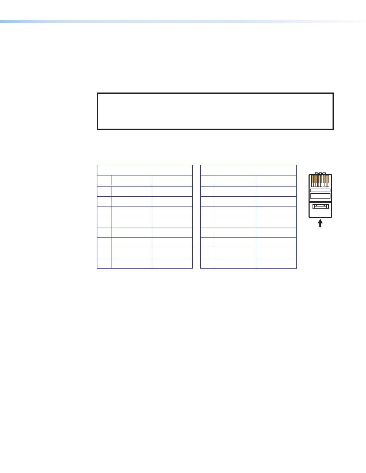
• Crossover cable — Wire one end of the twisted pair cable with the T568A standard
and the other with the T568B standard. Use this to connect to a computer.
• Straight-through (patch) cable — Wire both ends of the twisted pair cable with the
T568B standard. Use this to connect to a switch, hub, or router.
Straight-Through Cable
Pin End 1 Wire End 2 Wire
1 White-orange White-orange
2 Orange Orange
3 White-green White-green
4 Blue Blue
5 White-blue White-blue
6 Green Green
7 White-brown White-brown
8 Brown Brown
Figure 16. RJ-45 Pin Assignment for Ethernet Communication
Pin End 1 Wire End 2 Wire
1 White-green White-orange
2 Green Orange
3 White-orange White-green
4 Blue Blue
5 White-blue White-blue
6 Orange Green
7 White-brown White-brown
8 Brown Brown
Crossover Cable
12345678
Insert T
Pair Wires
XTP II CrossPoint Series • Installation 21
Page 30
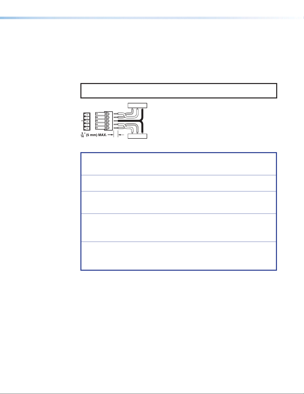
RS-232 and IR Over XTP Communication
RS-232 IR
IR Device
RS-232 Device
RS-232 and IR Over XTP connectors pass serial signals (such as projector control signals)
and infrared data. To pass bidirectional serial command signals between XTP-compatible
devices, connect a control device or device to control to the three poles (Tx, Rx, and G)
under “RS-232” of the 5-pole captive screw connector. To transmit and receive IR signals,
connect a control device or device to control to the three poles (G, Tx, and Rx) under “IR.”
The ground (G) pole is shared.
NOTE: RS-232 and IR data can be transmitted or received simultaneously (see
figure 17 for wiring considerations).
TxRx
Tx/Rx
Pins
RxTx
G
RxTx
Figure 17. RS-232 and IR Over XTP Connector Wiring Configuration
ATTENTION: The length of the exposed wires in the stripping process is critical.
ATTENTION : La longueur des câbles exposés est primordiale lorsque l’on entreprend
de les dénuder.
• The ideal length is 3/16 inch (5 mm).
• La longueur idéale est de 5mm (3/16inches).
G
RxTx
G
• If they are too long, the wires may touch, causing a short circuit between them.
• S’ils sont trop longs, les câbles exposés pourraient se toucher et provoquer un
court circuit.
• If they are too short, they can be easily pulled out, even if tightly fastened by the
captive screws.
• S’ils sont trop courts, ils peuvent être tirés facilement, même s’ils sont
correctement serrés par les borniers à vis.
• Do not tin the wires. Tinned wire does not hold its shape and can become loose
over time.
• Ne pas étamer les câbles. Les câbles étamés ne sont pas aussi bien fixés dans les
borniers à vis captives et pourraient s’arracher.
XTP II CrossPoint Series • Installation 22
Page 31

Analog Video Connection
15
Wire the 15-pin HD connector for RGBHV, RGBs, RGsB, component (bi-level or tri-level
sync), S-video, or composite video signals. The connector also supports EDID emulation.
See the following table for pin assignment details.
15
11
Figure 18. 15-Pin HD Connector Pins
15-Pin HD Connector Pinout Table
Pin RGBHV RGBs RGsB Component S-video Composite
1 Red Red Red R-Y
2 Green Green Green/Sync Y Luma Video
3 Blue Blue Blue B-Y Chroma
4
5
6 Red return Red return Red return R-Y return
7 Green return Green return Green return Y return Luma return Video return
8 Blue return Blue return Blue return B-Y return C return
9
10 Ground Ground Ground
11
12 EDID/DDC EDID/DDC EDID/DDC
13 H sync C sync
14 V sync
EDID/DDC
15
return
EDID/DDC
return
XTP II CrossPoint Series • Installation 23
Page 32

HDMI Connection
1
To secure an HDMI cable to an HDMI connector, use an Extron LockIt Cable Lacing Bracket
and a tie wrap.
3
3
4
2
5
Figure 19. LockIt Cable Lacing Bracket Installation
1. Plug the HDMI cable into the panel connection (see figure 19, 1).
2. Loosen the HDMI connection mounting screw from the panel (2) enough to allow the
LockIt to be placed over it. The screw does not have to be removed.
3. Place the LockIt on the screw and against the HDMI connector (3), and then tighten
the screw to secure the bracket.
4. Loosely place the included tie wrap around the HDMI connector and the LockIt (4).
5. While holding the connector securely against the cable lacing bracket, use pliers or
similar tools to tighten the tie wrap, then remove any excess length (5).
ATTENTION:
• Connect and pull the tie wraps until they are secure. Do not overtighten.
• Connectez et tirez les serre-câbles jusqu’à ce qu’ils soient sécurisés.
N’effectuez pas de serrage excessif.
XTP II CrossPoint Series • Installation 24
Page 33

Analog Audio Connection
Slee
No Ground Here
Unbalanced Audio InputBalanced Audio Input
Slee
Do not tin the wires!
Tip (+)
3.5 mm Stereo Plug Connector
(balanced)
Wire the audio input and output connectors as shown in figure 19. Use the supplied tie
wrap to secure the audio cable to the extended tail of the connector.
Tip
Ring
ves
Tip
Ring
Balanced Audio Output
Tip
Ring
ves
Tip
Ring
LR
Sleeves
No Ground Here
Unbalanced Audio Output
LR
Tip
Sleeve
Tip
Sleeve
Tip
Tip
LR
LR
Figure 20. Analog Audio Wiring Configuration
ATTENTION:
• For unbalanced audio, connect the sleeves to the ground contact. Do not connect
them to negative (–) contacts.
• Pour l’audio asymétrique, connectez les manchons au contact au sol. Ne PAS
connecter les manchons aux contacts négatifs (–).
• The length of the exposed wires in the stripping process is critical. The ideal length
is 3/16 inch (5 mm). If the exposed portion is longer, the wires may touch, causing
a short circuit between them. If the exposed wires are shorter, they can be easily
pulled out, even if tightly fastened by the captive screws.
• La longueur des câbles exposés est primordiale lorsque l’on entreprend de les
dénuder. S’ils sont un peu plus longs, les câbles exposés pourraient se toucher et
provoquer un court circuit. S’ils sont un peu plus courts, ils pourraient sortir, même
s’ils sont attachés par les vis captives.
• Do not tin the wires. Tinned wire does not hold its shape and can become loose
over time.
• Ne pas étamer les câbles. Les câbles étamés ne sont pas aussi bien fixés dans les
terminaisons des connecteurs à vis captives et pourraient sortir.
See figure 21 for wiring considerations for TRS or RCA connectors.
Tip (+)
Sleeve ( )
RCA Connector
Ring (-)
Sleeve ( )
Figure 21. Typical Audio Connectors
XTP II CrossPoint Series • Installation 25
Page 34

Front Panel
X
EF
EF
EFG
Operation
This section describes the front panel features and operation of the XTP II CrossPoint Series
matrix switchers. Topics in this section include the following:
• Front Panel Features
• Front Panel Operation
• Analog Audio Optimization
• RS-232 Insertion
Front Panel Features
• NVRAM modes
• Reset Modes
• Troubleshooting
ABCD
2
1
18
17
34
33
50
49
2
1
18
17
34
33
50
49
INPUTS
3
5
4
6 7
10
12
13
9
8
22 23
38 39
54 55
6 7
22 23
38
54
11
26
28
29
25
27
24
42
44
45
41
43
40
58
60
61
57
59
56
10
12
13
9
8
11
26
28
29
25
27
24
39
42
44
45
41
40
43
55
58
60
61
57
56
59
OUTPUTS
19
21
20
35
37
36
51
53
52
3
5
4
19
21
20
35
37
36
51
53
52
ABCD
ABCD
2
1
2
1
TP II CrossPoint 1600 XTP II CrossPoint 6400
INPUTS
3
5
4
67
10
12
13
9
8
OUTPUTS
3
5
4
7
6
10
9
8
16
14
11
15
CONTROL
12
13
16
14
11
15
CONFIG
ENTER PRESET
ESC
VIDEO
VIEW
PRIMARY
REDUNDANT
POWER
XTP CrossPoint 1600
XTP SERIES DIGITAL MATRIX SWITCHER
I/O
AUDIO
2
1
18
17
19
2
1
18
17
19
XTP II CrossPoint 3200
INPUTS
3
5
4
6 7
10
12
13
9
8
21
20
22 23
26
25
24
3
5
4
7
6
10
9
8
21
20
23
22
26
25
24
OUTPUTS
16
14
11
15
28
29
32
30
27
31
12
13
14
11
15
29
28
30
27
31
CONTROL
ENTERPRESET
VIEW
3
1
2
4
POWER
XTP CROSSPOINT 3200
XTP SERIES DIGITAL MATRIX SWITCHER
I/O
AUDIO
ESC
VIDEO
16
CONFIG
32
16
14
15
32
30
31
48
46
47
64
62
63
CONTROL
I/O
AUDIO
ESC
ENTERPRESET
VIDEO
VIEW
16
14
15
CONFIG
32
30
31
46
47
62
63
48
64
3
1
2
4
POWER
OPEN
XTP II CROSSPOINT 6400
XTP SERIES DIGITAL MATRIX SWITCHER
LOCK
Input buttons
A
(see the next page)
Output buttons
B
Control buttons
C
I/O buttons
D
Configuration connector
E
Power LED indicators
F
Door lock
G
Figure 22. Front Panel Features
XTP II CrossPoint Series • Front Panel Operation 26
Page 35

Input buttons — Press an input button to select an input, preset, or audio level. Input
A
buttons 1 and 2 also select background illumination settings (see Button Illumination
Summary on page42).
Output buttons — Press an output button to select an output or preset.
B
Control buttons — Include the Enter, Preset, View (<), and Esc (>) buttons. Press
C
them for the following:
• Enter button — Press this button to accept pending changes to settings or
presets. In conjunction with the other control buttons, this button also enables
Serial Port Configuration mode.
• Preset button — Press this button to enable Preset mode. In conjunction with the
other control buttons, this button also enables Serial Port Configuration mode.
• View (<) button — Press this button to enable View mode or decrease the input
audio level or output volume. In conjunction with the other control buttons, this
button also enables Serial Port Configuration mode or a Front Panel Lockout mode.
• Esc (>) button — Press this button to cancel pending changes to settings or
presets or increase the input audio level or output volume. In conjunction with the
other control buttons, this button also enables Serial Port Configuration mode or a
Front Panel Lockout mode.
I/O buttons — Include the Audio and Video buttons. Press them for the following:
D
• Video button — Press this button to select video for ties or RS-232 protocol in
Serial Port Configuration mode. With the Audio button, this button also performs a
system reset.
• Audio button — Press this button to select audio for ties or RS-422 protocol in
Serial Port Configuration mode. With the Video button, this button also performs a
system reset.
Configuration connector — Connect a host device (such as a PC) to the USB mini-B
E
connector.
Power LED indicators — Light when power is applied to associated power supply.
F
NOTES:
• The XTP II CrossPoint 1600 has two power supplies with two optional,
redundant power supplies.
• Left Primary LED — Corresponds to the 12 V power supply.
• Right Primary LED — Corresponds to the 48 V power supply (also
provides XTP remote power.
• Left Redundant LED — Corresponds to the redundant 12 V power supply.
• Right Redundant LED — Corresponds to the redundant 48 V power
supply.
• The other XTP II CrossPoint Series matrix switchers have four power supplies.
• LEDs 1 and 2 — Correspond to the two primary 12 V power supplies.
• LED 3 — Corresponds to the redundant 12 V power supply.
• LED 4 — Corresponds to the 48 V power supply (also provides XTP remote
power).
• Green — Indicates the power supply is operating within normal tolerances.
• Red — Indicates the power supply is operating outside normal tolerances or has
failed.
Door lock — Insert the key into the slot and rotate to lock or unlock the door.
G
XTP II CrossPoint Series • Front Panel Operation 27
Page 36

Front Panel Operation
Front Panel Tie Management
When power is applied, the matrix switcher performs a diagnostics test. The front panel
buttons blink red, green, and amber before returning to the button background illumination
setting. If the test is successful, the Video and Audio button light. After the test, the most
recent configuration is loaded.
If an error occurs during the test, the matrix switcher locks all operation. If this occurs, call
the Extron S3 Sales and Technological Support Hotline (see the Extron website for contact
information).
NOTE: By default, the matrix switcher is set in lock mode 2 (see Front Panel Lockout
Modes on page34 for a detailed list of basic and advanced functions and the
procedure to set the various front panel locks).
A tie is a connection between an input and output. Perform the following to create or
remove a tie.
NOTES:
• An output supports one video input and one audio input only.
• Making a new tie to an output that is already tied to another input overwrites
the previous tie.
1. Press the Esc button to clear pending actions.
2. Press the I/O buttons to select a type of tie to make or remove. The I/O button lights
when selected.
• Press the Video button to select video-only.
• Press the Audio button to select audio-only.
• Press both the Video and Audio buttons to select both video and audio.
3. Press the input button that corresponds to the desired input source. The selected input
button lights along with currently tied outputs (if applicable).
NOTE: The buttons light or blink in the following colors:
• Amber — Indicates video and audio ties.
• Green — Indicates video-only ties.
• Red — Indicates audio-only ties.
4. Perform one of the following:
• Press the output buttons that correspond to the desired untied output devices to
make ties.
• Press the output buttons that correspond to the desired tied output devices to
remove ties.
The output buttons blink along with the Enter button.
5. Press the Enter button to accept the pending changes. The buttons return to the
regular illumination.
XTP II CrossPoint Series • Front Panel Operation 28
Page 37

Front Panel Tie Configuration View
Input
buttons
Preset
1
Preset6Preset
7
Preset
10
Preset15Preset
16
Preset
11
Preset
3
Preset8Preset
9
Preset4Preset
5
Preset13Preset
14
Preset
12
Preset
2
INPUTS
1
2
3 4
5
6
7
8
9
10
11
12
14
15
16
13
A tie configuration includes all ties within the matrix switcher. Use the view configuration mode to
view the configuration while preventing unintentional changes to the current configuration.
NOTE: The view mode automatically discontinues after 30 seconds of front panel inactivity.
1. Press the Esc button to clear pending actions.
2. Press the View button. The View button along with output buttons that correspond to
untied outputs light or blink.
NOTE: The output buttons light in the following colors:
• Amber — Indicates there are no video or audio ties.
• Green — Indicates there is no video tie.
• Red — Indicates there is no audio tie.
If an output button blinks, the output is muted.
3. Press the I/O buttons to select a type of tie to view. The I/O button lights when selected.
• Press the Video button to view video ties only.
• Press the Audio button to view audio ties only.
• Press both the Video and Audio button to view video and audio ties.
4. Press the input or output button that corresponds to the desired input or output device. The
tied input or output buttons light.
NOTE: The buttons light in the following colors:
• Amber — Indicates a video and audio tie.
• Green — Indicates a video-only tie.
• Red — Indicates a audio-only tie.
5. Press the View button to discontinue the view mode.
Front Panel Preset Management
A preset saves configuration information to be recalled later. There are 32 presets available.
When a preset is recalled, it becomes the current configuration.
• Preset numbers 1 through 16 are assigned to the input buttons, and are available to be
either saved or retrieved using the front panel (see image below).
• Preset numbers 17 through 32 are available using SIS commands (see the Presets
commands on page 51).
NOTES:
• Only audio and video ties are saved with presets.
• Audio input gain is not saved and does not change when a preset is recalled.
• To view preset configurations from the front panel, recall the preset.
• When power is removed and restored, the matrix switcher retains the current
configuration and presets.
• The matrix switcher does not save the current configration when a preset is recalled
unless the current configuration is also saved as a preset.
XTP II CrossPoint Series • Front Panel Operation 29
Page 38

Save a preset from the front panel
1. Press the Esc button to clear pending actions.
2. Hold the Preset button in until it blinks (approximately 2 seconds). The Preset button
remains lit. The input or output buttons that correspond to presets with a saved
configuration light as well.
3. Press the input button that corresponds to the desired preset number. The selected
button blinks along with the Enter button.
4. Press the Enter button to save the preset.
Recall a preset from the front panel
1. Press the Esc button to clear pending actions.
2. Press the Preset button. The Preset button along with any input or output buttons
that correspond to presets with a saved configuration light.
3. Press the input or output button that corresponds to the desired preset. The selected
input or output button blinks along with the Enter button.
4. Press the Enter button.
Front Panel Analog Audio Input Levels
Each analog audio input level has a range of -18 dB to +24 dB (0 dB is default). Adjust
the analog audio input to ensure there is no noticeable output volume difference between
sources. To adjust the analog audio input levels from the front panel, remove any front panel
locks that prevent front panel operation (see Front Panel Lockout Modes on page34).
NOTE: Gain and attenuation apply to local inputs only.
1. Press the Esc button to clear pending actions.
2. Hold the Audio button until the button blinks.
3. Press the input button that corresponds to the desired analog audio input. The output
buttons light to indicate the current audio level.
NOTES:
• Each output button represents 1 dB except on 1600 models. On 1600 models,
each output button represents 1 dB when blinking and 2 dB when lit steadily.
• When output buttons light or blink green, gain is applied to the audio level.
• When output buttons light or blink red, attenuation is applied to the audio level.
4. Press the Esc to increase the audio level or the View button to decrease the audio level.
Highest Numbered Output Button Illumination for Analog Audio Input Levels
1600 Models Other Models
dB Button # Button Color/State Button # Button Color/State
24 12 Green/Solid 24 Green/Solid
23 12 Green/Blinking 23 Green/Solid
22 11 Green/Solid 22 Green/Solid
21 11 Green/Blinking 21 Green/Solid
20 10 Green/Solid 20 Green/Solid
19 10 Green/Blinking 19 Green/Solid
18 9 Green/Solid 18 Green/Solid
XTP II CrossPoint Series • Front Panel Operation 30
Page 39

Highest Numbered Output Button Illumination for Analog Audio Input Levels
1600 Models Other Models
dB Button # Button Color/State Button # Button Color/State
17 9 Green/Blinking 17 Green/Solid
16 8 Green/Solid 16 Green/Solid
15 8 Green/Blinking 15 Green/Solid
14 7 Green/Solid 14 Green/Solid
13 7 Green/Blinking 13 Green/Solid
12 6 Green/Solid 12 Green/Solid
11 6 Green/Blinking 11 Green/Solid
10 5 Green/Solid 10 Green/Solid
9 5 Green/Blinking 9 Green/Solid
8 4 Green/Solid 8 Green/Solid
7 4 Green/Blinking 7 Green/Solid
6 3 Green/Solid 6 Green/Solid
5 3 Green/Blinking 5 Green/Solid
4 2 Green/Solid 4 Green/Solid
3 2 Green/Blinking 3 Green/Solid
2 1 Green/Solid 2 Green/Solid
1 1 Green/Blinking 1 Green/Solid
0 Unlit Unlit
-1 1 Red/Blinking 1 Red/Solid
-2 1 Red/Solid 2 Red/Solid
-3 2 Red/Blinking 3 Red/Solid
-4 2 Red/Solid 4 Red/Solid
-5 3 Red/Blinking 5 Red/Solid
-6 3 Red/Solid 6 Red/Solid
-7 4 Red/Blinking 7 Red/Solid
-8 4 Red/Solid 8 Red/Solid
-9 5 Red/Blinking 9 Red/Solid
-10 5 Red/Solid 10 Red/Solid
-11 6 Red/Blinking 11 Red/Solid
-12 6 Red/Solid 12 Red/Solid
-13 7 Red/Blinking 13 Red/Solid
-14 7 Red/Solid 14 Red/Solid
-15 8 Red/Blinking 15 Red/Solid
-16 8 Red/Solid 16 Red/Solid
-17 9 Red/Blinking 17 Red/Solid
-18 9 Red/Solid 18 Red/Solid
5. Press the Audio button to exit the Audio mode. The Audio button stops blinking.
XTP II CrossPoint Series • Front Panel Operation 31
Page 40

Front Panel Output Mutes
The matrix switcher can mute audio, video, or both on any output. To mute or unmute an
output from the front panel, remove any front panel locks that prevent front panel operation
(see Front Panel Lockout Modes on page34).
NOTE: The matrix switcher retains mute settings after power is removed and restored.
To toggle output mutes, perform the following:
1. Press the Esc button to clear pending actions.
2. Press the View button. The View button and output buttons that correspond to untied
outputs light or blink.
NOTE: The input and output buttons light in the following colors:
• Amber — Indicates there are no video or audio ties.
• Green — Indicates there is no video tie.
• Red — Indicates there is no audio tie.
3. Press the I/O buttons to select the type of mute.
• Press the Video button to mute the video only.
• Press the Audio button to mute the audio only.
• Press both the Video and Audio button to mute the video and audio.
4. For each desired output, hold the corresponding output button in until it either starts
blinking or stops blinking (approximately 2 seconds). Hold the buttons one at a time.
NOTE: The output buttons blink in the following colors:
• Amber — Indicates the video and audio is muted.
• Green — Indicates only the video is muted.
• Red — Indicates only the audio is muted.
If an output button is illuminated with a tie, it also maintains the view color
5. Press the View button to accept the changes.
Front Panel Output Volume
There are 65 steps of volume attenuation. The volume ranges from 0% to 100%. To adjust
the output volume of an output from the front panel, remove any front panel locks that
prevent front panel operation (see Front Panel Lockout Modes on page34).
NOTE: Output volume applies to local inputs only.
1. Press the Esc button to clear pending actions.
2. Hold the Audio button until the button blinks.
3. Press the output button that corresponds to the desired output. The input buttons
display the current output volume for the selected output.
4. Press the Esc button to increase the volume or the View button to decrease the
volume.
TIP: Hold the Esc or View button to change the volume 3 dB per second.
XTP II CrossPoint Series • Front Panel Operation 32
Page 41

Highest Numbered Input Button For Audio Output Volume
1600 Model Other Models 1600 Model Other Models
Volume Attenuation Button State Button State Volume Attenuation Button State Button State
100.0% 0 dB 16 Solid 32 Solid 50.5% 33 dB 8 Blinking 16 Blinking
98.5% 1 dB 16 Blinking 32 Blinking 49.0% 34 dB 8 Blinking 15 Solid
97.0% 2 dB 16 Blinking 31 Solid 47.5% 35 dB 8 Blinking 15 Blinking
95.5% 3 dB 16 Blinking 31 Blinking 46.0% 36 dB 7 Solid 14 Solid
94.0% 4 dB 15 Solid 30 Solid 44.5% 37 dB 7 Blinking 14 Blinking
92.5% 5 dB 15 Blinking 30 Blinking 43.0% 38 dB 7 Blinking 13 Solid
91.0% 6 dB 15 Blinking 29 Solid 41.5% 39 dB 7 Blinking 13 Blinking
89.5% 7 dB 15 Blinking 29 Blinking 40.0% 40 dB 6 Solid 12 Solid
88.0% 8 dB 14 Solid 28 Solid 38.5% 41 dB 6 Blinking 12 Blinking
86.5% 9 dB 14 Blinking 28 Blinking 37.0% 42 dB 6 Blinking 11 Solid
85.0% 10 dB 14 Blinking 27 Solid 35.5% 43 dB 6 Blinking 11 Blinking
83.5% 11 dB 14 Blinking 27 Blinking 34.0% 44 dB 5 Solid 10 Solid
82.0% 12 dB 13 Solid 26 Solid 32.5% 45 dB 5 Blinking 10 Blinking
80.5% 13 dB 13 Blinking 26 Blinking 31.0% 46 dB 5 Blinking 9 Solid
79.0% 14 dB 13 Blinking 25 Solid 29.5% 47 dB 5 Blinking 9 Blinking
77.5% 15 dB 13 Blinking 25 Blinking 28.0% 48 dB 4 Solid 8 Solid
76.0% 16 dB 12 Solid 24 Solid 26.5% 49 dB 4 Blinking 8 Blinking
74.5% 17 dB 12 Blinking 24 Blinking 25.0% 50 dB 4 Blinking 7 Solid
73.0% 18 dB 12 Blinking 23 Solid 23.5% 51 dB 4 Blinking 7 Blinking
71.5% 19 dB 12 Blinking 23 Blinking 22.0% 52 dB 3 Solid 6 Solid
70.0% 20 dB 11 Solid 22 Solid 20.5% 53 dB 3 Blinking 6 Blinking
68.5% 21 dB 11 Blinking 22 Blinking 19.0% 54 dB 3 Blinking 5 Solid
67.0% 22 dB 11 Blinking 21 Solid 17.5% 55 dB 3 Blinking 5 Blinking
65.5% 23 dB 11 Blinking 21 Blinking 16.0% 56 dB 2 Solid 4 Solid
64.0% 24 dB 10 Solid 20 Solid 14.5% 57 dB 2 Blinking 4 Blinking
62.5% 25 dB 10 Blinking 20 Blinking 13.0% 58 dB 2 Blinking 3 Solid
61.0% 26 dB 10 Blinking 19 Solid 11.5% 59 dB 2 Blinking 3 Blinking
59.5% 27 dB 10 Blinking 19 Blinking 10.0% 60 dB 1 Solid 2 Solid
58.0% 28 dB 9 Solid 18 Solid 8.5% 61 dB 1 Blinking 2 Blinking
56.5% 29 dB 9 Blinking 18 Blinking 7.0% 62 dB 1 Blinking 1 Solid
55.0% 30 dB 9 Blinking 17 Solid 5.5% 63 dB 1 Blinking 1 Blinking
53.5% 31 dB 9 Blinking 17 Blinking 0.0% 76 dB Unlit Unlit
52.0% 32 dB 8 Solid 16 Solid
5. Press the Audio button to save the audio settings and exit Audio mode.
XTP II CrossPoint Series • Front Panel Operation 33
Page 42

Front Panel Lockout Modes
Front panel lockout modes prevent operation from the front panel to varying degrees. The
modes include the following:
• Lock mode 0 — Allows front panel operation.
• Lock mode 1 — Prevents all front panel operation except for changing the front panel
lockout mode and viewing some settings.
• Lock mode 2 — Prevents the following front panel operation:
• Audio output mutes
• Audio output volume
• Remote serial connector protocol and baud rate
The following features remain available:
• Tie management
• Preset management
• Audio input level
• Front panel lockout modes
NOTE: The matrix switcher is shipped from the factory in lock mode 2.
To toggle the front panel lockout mode between lock mode 1 and 2, press the View and
Esc buttons simultaneously until the two buttons blink twice (about 2 seconds).
NOTE: If the matrix switcher is in lock mode 0, this enables lock mode 2.
To toggle the front panel lockout mode between lock mode 0 and 2, press the Preset,
View, and Esc buttons simultaneously until the three buttons blink twice (about 2 seconds).
Front Panel Remote Port Settings
The rear panel serial port supports RS-232 or RS-422 serial protocol and 9600, 19200,
38400, or 11520 baud rate. To define the rear panel serial port protocol and baud rate from
the front panel, remove any front panel locks that prevent front panel operation (see Front
Panel Lockout Modes above).
1. Hold the four control buttons (Enter, Preset, View, and Esc) until they and the I/O
buttons light or blink (about 2 seconds).
NOTES:
• Three control buttons light and one blinks.
• One I/O button lights and one blinks.
• The blinking button is the current setting.
2. Press the desired control or I/O button. The button blinks. See the following table for
button definitions.
Front Panel Button Baud Rate and Protocol Settings
Control Buttons I/O Buttons
Button Baud Rate Button Protocol
Enter 9600 Video RS-232
Preset 19200 Audio RS-422
View 38400
Esc 115200
3. Press an output button to save the settings and exit configuration mode.
XTP II CrossPoint Series • Front Panel Operation 34
Page 43

Front Panel Reset
This reset performs the following functions:
• Clears all ties and presets.
• Unmutes all outputs.
• Disables all RS-232 output inserts.
• Resets all input audio levels to unity gain (0 dB).
• Sets all output volume levels to 100% (0 dB of attenuation).
Use this reset to reset settings to factory default values.
1. Hold the View and Esc buttons in simultaneously until the end of step 3.
2. Apply AC power to the matrix switcher while still holding the two front panel buttons.
The front panel buttons and indicators blink before turning off.
3. Release the View and Esc buttons when the front panel buttons return to the default
illumination, except the Video and Audio buttons which light.
Button Background Illumination
The button background illumination setting determines the default illumination state of front
panel buttons. The buttons can either not light or light a dim amber color. To change the
button background illumination setting from the front panel, remove any front panel locks
that prevent front panel operation (see Front Panel Lockout Modes on the previous
page).
1. Press the Esc button to clear pending actions.
2. Hold the Input 1 and Input 2 buttons simultaneously until the front panel buttons
change in illumination (about 2 seconds).
XTP II CrossPoint Series • Front Panel Operation 35
Page 44

Analog Audio Optimization
To ensure the best headroom, the optimal signal-to-noise ratio, and that there is no
noticeable volume difference between sources, consider the following:
1. Wire analog audio inputs and outputs for balanced audio (see Analog Audio
Connection on page25).
2. If the audio source has output level control, set the output to the maximum level or 0 dB
of attenuation.
3. If the audio source is connected to an XTP transmitter or switcher, set the audio settings
of the XTP device to the default values.
4. If the audio output device has output level control, set the output to the maximum level
or 0 dB of attention.
5. If the audio output device is connected to an XTP receiver or scaler, set the audio
settings of the XTP device to the default value.
6. Make the desired configuration ties for the matrix system.
7. Switch among inputs, listening to the audio output or measuring the audio output level
with test equipment (such as a VU meter).
8. As necessary, adjust the audio input level for analog audio.
• If the audio source is connected directly to the matrix switcher, adjust the audio
• If the audio source is connected to another XTP device (such as an XTP transmitter
9. Tie an audio input to each output.
10. As necessary, adjust the output audio volume.
• If the audio output device is connected directly to the matrix switcher, adjust the
• If the audio output device is connected to another XTP device (such as an XTP
input level so that the approximate output level is the same for all inputs.
or switcher) before the signal reaches the matrix switcher, adjust the audio input
level on the XTP device.
output volume
receiver or scaler) before the signal reaches it, adjust the output volume on the XTP
device.
RS-232 Insertion
RS-232 insertion determines how RS-232 serial control signals are passed through the
matrix switcher to connected devices. The RS-232 serial control signals always extends to
the RS-232 Over XTP connector on a connected XTP device, but there are two methods of
insertion on the matrix switcher: Ethernet to RS-232 insertion and captive screw insertion.
• Ethernet to RS-232 insertion — Passes serial control signals between a device
• Captive screw insertion — Passes serial control signals between a device connected
To enable XTP ports for either insertion method, use the XTP System Configuration Software
(see the XTP System Configuration Software Help file).
NOTE: The RS-232 Over XTP connectors support up to a 115k baud rate.
connected to the LAN connector on the matrix switcher and an XTP device connected
to an XTP twisted pair or fiber board.
to an RS-232 Over XTP connector on an XTP twisted pair or fiber board and an XTP
device connected to the corresponding XTP connector on the same XTP board.
NOTE: Ensure the captive screw connector used for insertion is physically
connected to another device.
XTP II CrossPoint Series • Front Panel Operation 36
Page 45

Ethernet to RS-232 Insertion
Modular Digital Matrix Switcher
Extron
I
IP
Contro
Ethernet to RS-232 insertion allows control of a device from a remote location over the Ethernet
network. For example, an Extron IPCP control processor, connected to the matrix switcher LAN
connecter, controlling a camera, connected to an XTP transmitter which is connected to an XTP
input connector in the matrix switcher (see below).
PCP PRO 555
Link Pro
l Processor
100-240V ~ 50-60Hz
1.2A MAX
1 2
SWITCHED 12 VDC
40W MAX TOTAL
3 4
12 VDC
142 3 7
TxRx GTxRxGTxRx GTxRxG
5 6 8
TxRx GTxRxGTxRx GTxRxG
COM
SGSG S GSG
RTS
CTS
5 6 7 8 5 6 7 8
SGSG S GSG
RTSCTS
PWR OUT = 12W
1 2 3 41 2 3 4
+V+S -S G
eBUS
FLEX I/ORELAYSIR/SERIAL
LAN
AV
3214G
LAN
HD Camera
RS-232
0.7A MAX
POWER
12V
INPUTS
XTP T HD 4K
HDMI
LOOP THRU
AUDIO
AUDIO
LR
ON
OFF
−+
−+
OVER XTP
RS-232 IR
Rx GTx
SIG LINK
RxTx
XTP OUT
RESET
LAN
Extron
Network
Ethernet
XTP CROSSPOINT 1600
INPUTS
DISCONNECT POWER
CORD BEFORE
100-240V
SERVICING
50-60Hz
12.0A MAX
OUTPUTS
SIGLINK
INPUTS
INPUTS
PWR
1−4
XTP IN
LANLAN LANLAN
INPUTS
5−8
SIGLINK
INPUTS
PWR
9−12
XTP IN
INPUTS
13−16
OUTPUTS
1−4
LANLAN LANLAN
OUTPUTS
5−8
SIGLINK
OUTPUTS
PWR
9−12
XTP OUT
OUTPUTS
13−16
XTP IN
SIG LINK
LAN
LAN
RS-232/422
REMOTELAN
XTP OUT
SIG LINK
LAN
SIGLINK
PWR
SIG LINK
XTP IN
SIGLINK
PWR
XTP IN
XTP OUT
SIG LINK
SIGLINK
PWR
XTP OUT
XTP IN
PWR
LAN
PWR
LAN
RESET
PWR
LAN
XTP T HD 4K
XTP Transmitter for HDMI
RS-232
SIGLINK
XTP IN
SIGLINK
XTP IN
SIGLINK
XTP OUT
XTP IN
SIG LINK
LAN
LAN
XTP OUT
SIG LINK
LAN
SIGLINK
PWR
XTP IN
SIGLINK
PWR
XTP IN
SIGLINK
PWR
XTP OUT
XTP IN
RS-232
RS-232
RS-232
RS-232
IR
SIG LINK
SIG LINK
IR
Tx Rx GTxRx
Tx Rx GTxRx
TxRx GTxRx
TxRx GTxRx
LAN
LRLR LR LR
RS-232
RS-232
IR
TxRx GTxRx
TxRx GTxRx
LAN
XTP OUT
LAN
LRLRLR
LR
RS-232
RS-232
IR
Tx Rx GTxRx
Tx Rx GTxRx
LRLR LR LR
RS-232
RS-232
IR
TxRx GTxRx
TxRx GTxRx
LR LR LR LR
OVER XTP
OVER FIBER
IR
IR
AUDIO
OVER XTP
IR
AUDIO
OVER FIBER
IR
AUDIO
OVER XTP
IR
AUDIO
RS-232
RS-232
Tx Rx GTxRx
TxRx GTxRx
RS-232
TxRx GTxRx
RS-232
Tx Rx GTxRx
RS-232
TxRx GTxRx
RS-232
RS-232
IR
IR
Tx Rx GTxRx
TxRx GTxRx
RS-232
IR
TxRx GTxRx
RS-232
IR
Tx Rx GTxRx
XTP CP 4o HD 4K PLUS
RS-232
IR
TxRx GTxRx
XTP CP 4i 4K
XTP CP 4i FIBER 4K
IR
IR
XTP CP 4i HD 4K PLUS
XTP CP 4i 4K
IR
XTP CP 4i VGA
XTP CP 4o FIBER 4K
IR
XTP CP 4o 4K
IR
XTP CP 4o SA
Extron
XTP CrossPoint 1600
Figure 23. Typical Ethernet to RS-232 Insertion
Each XTP twisted pair or fiber input and output connector on the matrix switcher has a
dedicated UART port number. The number of XTP inputs and outputs determine the total
number of available ports. To determine the numbers for the ports, set a starting number for the
RS-232 and RS-422 connector. Each additional input starts numbering sequentially after two
numbers greater than the starting value. Each output starts numbering sequentially after the
maximum number of possible inputs (33 for 1600 and 3200 models, and 65 for 6400 models).
To change the starting point, use the XTP System Configuration Software (see the XTP System
Configuration Software Help file).
NOTE: Ensure the RS-232 protocol matches the connected device. To do this, use the XTP
System Configuration Software (see the XTP System Configuration Software Help file).
XTP II CrossPoint Series • Front Panel Operation 37
Page 46

Modular Digital Matrix Switcher
Blu-Ra
Captive Screw Insertion
Captive screw insertion allows control of a device from a remote location over the the
RS-232 Over XTP connector on the XTP twisted pair or fiber board. For example, an Extron
IPCP control processor, connected to an RS-232 Over XTP connector on an XTP twisted
pair input board, controll a Blu-Ray Disc player, connected to an XTP transmiiter which is
connected to the corresponding XTP input connector on the same XTP twisted pair input
board.
NOTE: Captive screw insertion applies only to the corresponding XTP connector to the
RS-232 Over XTP connector.
STANDBY/ON
STANDBY/ON
Extron
XTP T HD 4K
XTP Transmitter
PQLSHDMIOPEN/CLOSE FL OFF
PQLSHDMIOPEN/CLOSE FL OFF
USB
USB
y Player
INPUTS
POWER
POWER
12V
12V
0.7A MAX
0.7A MAX
INPUTS
XTP T HD 4K
XTP T HD 4K
HDMI
HDMI
XTP CROSSPOINT 1600
XTP CROSSPOINT 1600
LOOP THRU
LOOP THRU
DISCONNECT POWER
DISCONNECT POWER
CORD BEFORE
CORD BEFORE
SERVICING
SERVICING
100-240V
12.0A MAX
100-240V
12.0A MAX
50-60Hz
50-60Hz
AUDIO
AUDIO
ON
ON
OFF
OFF
Extron
XTP CrossPoint 1600
AUDIO
AUDIO
LR
LR
−+
−+
RS-232
SIG LINK
SIG LINK
OVER XTP
OVER XTP
RS-232 IR
RS-232 IR
−+
−+
RxTx
RxTx
Rx GTx
Rx GTx
XTP OUT
XTP OUT
RESET
RESET
LAN
LAN
RS-232
SIG LINK
SIG LINK
SIG LINK
XTP IN
XTP IN
SIG LINK
SIG LINK
XTP IN
XTP IN
SIG LINK
SIG LINK
XTP OUT
XTP OUT
XTP IN
XTP IN
SIGLINK
SIGLINK
LAN
LAN
LAN
LAN
RS-232/422
RS-232/422
REMOTE LAN
REMOTE LAN
XTP OUT
XTP OUT
SIGLINK
SIGLINK
LAN
LAN
SIG LINK
PWR
PWR
XTP IN
XTP IN
SIG LINK
SIG LINK
PWR
PWR
XTP IN
XTP IN
SIG LINK
SIG LINK
PWR
PWR
XTP OUT
XTP OUT
INPUTS
INPUTS
INPUTS
INPUTS
PWR
PWR
1−4
1−4
LAN LAN LANLAN
LAN LAN LANLAN
INPUTS
INPUTS
5−8
5−8
INPUTS
INPUTS
INPUTS
INPUTS
PWR
PWR
9−12
9−12
INPUTS
INPUTS
13−16
13−16
OUTPUTS
OUTPUTS
1−4
1−4
LAN LAN LANLAN
LAN LAN LANLAN
OUTPUTS
OUTPUTS
5−8
5−8
OUTPUTS
OUTPUTS
OUTPUTS
OUTPUTS
PWR
PWR
9−12
9−12
OUTPUTS
OUTPUTS
13−16
13−16
XTP IN
XTP IN
SIGLINK
SIGLINK
LAN
LAN
LAN
LAN
XTP OUT
XTP OUT
SIGLINK
SIGLINK
LAN
LAN
SIGLINK
SIGLINK
PWR
PWR
SIGLINK
SIGLINK
XTP IN
XTP IN
SIGLINK
SIGLINK
PWR
PWR
XTP IN
XTP IN
RESET
RESET
XTP OUT
XTP OUT
SIGLINK
SIGLINK
SIGLINK
SIGLINK
PWR
PWR
XTP OUT
XTP OUT
Extron
IPCP PRO 555
IP Link Pro
Control Processor
100-240V ~ 50-60Hz
100-240V ~ 50-60Hz
1 2
1 2
SWITCHED 12 VDC
SWITCHED 12 VDC
40W MAX TOTAL
40W MAX TOTAL
3 4
3 4
1.2A MAX
1.2A MAX
12 VDC
12 VDC
SIGLINK
SIGLINK
XTP IN
XTP IN
LAN
LAN
LAN
LAN
LAN
LAN
XTP IN
XTP IN
PWR
PWR
SIGLINK
SIGLINK
XTP IN
XTP IN
LAN
LAN
SIGLINK
SIGLINK
PWR
PWR
XTP IN
XTP IN
LAN
LAN
XTP OUT
XTP OUT
SIGLINK
SIGLINK
SIGLINK
SIGLINK
PWR
PWR
XTP OUT
XTP OUT
LAN
LAN
142 3 7
142 3 7
TxRx GTxRxGTxRx GTxRxG
TxRx GTxRxGTxRx GTxRxG
5 6 8
5 6 8
TxRx GTxRxGTxRx GTxRxG
TxRx GTxRxGTxRx GTxRxG
RS-232
RS-232
RS-232
RS-232
IR
IR
IR
IR
Tx Rx GTxRx
Tx Rx GTxRx
TxRx GTxRx
TxRx GTxRx
LRLR LR LR
LRLR LR LR
RS-232
RS-232
IR
IR
TxRx GTxRx
TxRx GTxRx
LR
LR
RS-232
RS-232
IR
IR
Tx Rx GTxRx
Tx Rx GTxRx
LRLR LR LR
LRLR LR LR
RS-232
RS-232
IR
IR
TxRx GTxRx
TxRx GTxRx
LRLR LR LR
LRLR LR LR
SGSG SGSG
SGSG SGSG
RTS
RTS
CTS
CTS
5 6 7 8 5 6 7 8
5 6 7 8 5 6 7 8
SGSG SGSG
SGSG SGSG
RTSCTS
RTSCTS
COM
COM
RS-232
Insertion
OVER XTP
OVER XTP
OVER FIBER
OVER FIBER
RS-232
RS-232
RS-232
RS-232
RS-232
RS-232
RS-232
RS-232
RS-232
RS-232
RS-232
RS-232
IR
IR
IR
IR
IR
IR
IR
IR
Tx Rx GTxRx
Tx Rx GTxRx
Tx Rx GTxRx
Tx Rx GTxRx
Tx Rx GTxRx
Tx Rx GTxRx
TxRx GTxRx
TxRx GTxRx
TxRx GTxRx
TxRx GTxRx
TxRx GTxRx
TxRx GTxRx
XTP CP 4i HD 4K PLUS
XTP CP 4i HD 4K PLUS
AUDIO
AUDIO
OVER XTP
OVER XTP
RS-232
RS-232
RS-232
RS-232
RS-232
RS-232
IR
IR
IR
IR
TxRx GTxRx
TxRx GTxRx
TxRx GTxRx
TxRx GTxRx
TxRx GTxRx
TxRx GTxRx
AUDIO
AUDIO
LRLRLR
LRLRLR
OVER FIBER
OVER FIBER
RS-232
RS-232
RS-232
RS-232
RS-232
RS-232
IR
IR
IR
IR
Tx Rx GTxRx
Tx Rx GTxRx
Tx Rx GTxRx
Tx Rx GTxRx
Tx Rx GTxRx
Tx Rx GTxRx
XTP CP 4o HD 4K PLUS
XTP CP 4o HD 4K PLUS
AUDIO
AUDIO
OVER XTP
OVER XTP
RS-232
RS-232
RS-232
RS-232
RS-232
RS-232
IR
IR
IR
IR
TxRx GTxRx
TxRx GTxRx
TxRx GTxRx
TxRx GTxRx
TxRx GTxRx
TxRx GTxRx
AUDIO
AUDIO
XTP CP 4i 4K
XTP CP 4i 4K
XTP CP 4i FIBER 4K
XTP CP 4i FIBER 4K
IR
IR
IR
IR
XTP CP 4i 4K
XTP CP 4i 4K
IR
IR
XTP CP 4i VGA
XTP CP 4i VGA
XTP CP 4o FIBER 4K
XTP CP 4o FIBER 4K
IR
IR
XTP CP 4o 4K
XTP CP 4o 4K
IR
IR
XTP CP 4o SA
XTP CP 4o SA
PWR OUT = 12W
PWR OUT = 12W
1 2 3 41 2 3 4
1 2 3 41 2 3 4
+V+S -S G
+V+S -S G
LAN
LAN
eBUS
eBUS
AV
AV
3214G
3214G
LAN
LAN
FLEX I/ORELAYSIR/SERIAL
FLEX I/ORELAYSIR/SERIAL
Figure 24. Typical Captive Screw Insertion Application
For Ethernet to RS-232 insertion, define the starting insertion port number. This number is
entered as the Telnet port number when establishing communication with the insertion port.
The rear panel Remote RS-232 and RS-422 connector and all input serial ports in the matrix
swticher are numbered sequentially (see the table on the next page). Output serial ports
start at 34 or 64 and continue on sequentially.
XTP II CrossPoint Series • Front Panel Operation 38
Page 47

Input UART Default Values
Matrix Switcher Model Model Model Model
Port 1600 3200 6400 Port 3200 6400 Port 6400 Port 6400
Serial 1999
Input 1 2001 Input 17 2017 Input 33 2033 Input 49 2049
Input 2 2002 Input 18 2018 Input 34 2034 Input 50 2050
Input 3 2003 Input 19 2019 Input 35 2035 Input 51 2051
Input 4 2004 Input 20 2020 Input 36 2036 Input 52 2052
Input 5 2005 Input 21 2021 Input 37 2037 Input 53 2053
Input 6 2006 Input 22 2022 Input 38 2038 Input 54 2054
Input 7 2007 Input 23 2023 Input 39 2039 Input 55 2055
Input 8 2008 Input 24 2024 Input 40 2040 Input 56 2056
Input 9 2009 Input 25 2025 Input 41 2041 Input 57 2057
Input 10 2010 Input 26 2026 Input 42 2042 Input 58 2058
Input 11 2011 Input 27 2027 Input 43 2043 Input 59 2059
Input 12 2012 Input 28 2028 Input 44 2044 Input 60 2060
Input 13 2013 Input 29 2029 Input 45 2045 Input 61 2061
Input 14 2014 Input 30 2030 Input 46 2046 Input 62 2062
Input 15 2015 Input 31 2031 Input 47 2047 Input 63 2063
Input 16 2016 Input 32 2032 Input 48 2048 Input 64 2064
Output UART Default Values
Matrix Switcher Model Model Model Model
Port 1600 3200 6400 Port 3200 6400 Port 6400 Port 6400
Output 1 2033 2065 Output 17 2049 2081 Output 33 2097 Output 49 2113
Output 2 2034 2066 Output 18 2050 2082 Output 34 2098 Output 50 2114
Output 3 2035 2067 Output 19 2051 2083 Output 35 2099 Output 51 2115
Output 4 2036 2068 Output 20 2052 2084 Output 36 2100 Output 52 2116
Output 5 2037 2069 Output 21 2053 2085 Output 37 2101 Output 53 2117
Output 6 2038 2070 Output 22 2054 2086 Output 38 2102 Output 54 2118
Output 7 2039 2071 Output 23 2055 2087 Output 39 2103 Output 55 2119
Output 8 2040 2072 Output 24 2056 2088 Output 40 2104 Output 56 2120
Output 9 2041 2073 Output 25 2057 2089 Output 41 2105 Output 57 2121
Output 10 2042 2074 Output 26 2058 2090 Output 42 2106 Output 58 2122
Output 11 2043 2075 Output 27 2059 2091 Output 43 2107 Output 59 2123
Output 12 2044 2076 Output 28 2060 2092 Output 44 2108 Output 60 2124
Output 13 2045 2077 Output 29 2061 2093 Output 45 2109 Output 61 2125
Output 14 2046 2078 Output 30 2062 2094 Output 46 2110 Output 62 2126
Output 15 2047 2079 Output 31 2063 2095 Output 47 2111 Output 63 2127
Output 16 2048 2080 Output 32 2064 2096 Output 48 2112 Output 64 2128
XTP II CrossPoint Series • Front Panel Operation 39
Page 48

NVRAM Modes
Centralized Mode (Default)
Distributed Mode
NVRAM modes determine how the matrix switcher communicates with connected endpoint
devices. There are two NVRAM modes—centralized mode and distributed mode—which can
be applied using the XTP System Configuration software (see the XTP System Configuration
Software Help file, available at www.extron.com). The user can configure each extended input
or output to work in one of these modes depending on the application.
By default, the XTP II CrossPoint matrix switchers operate in centralized mode. In this mode,
the matrix switcher is the “master” device in the system which stores all endpoint settings and
controls all changes to the endpoints.
If changes are made directly to the endpoints (such as input selection on a transmitter using the
buttons, or changes to a scaler using the on-screen display), these changes are pushed back
to the matrix and stored.
NOTE: Projectors and other XTP compatible devices work in this mode as well.
In this mode, the matrix switcher is no longer the master device in the system. When a port is
set up in distributed mode and an endpoint is connected, the settings are maintained on the
endpoint and pushed to the matrix to ensure that they are in sync.
NOTE:
• The user can still configure the endpoints from the matrix in this mode.
• Projectors and other XTP compatible devices work in this mode as well.
XTP II CrossPoint Series • Front Panel Operation 40
Page 49

Reset Modes
The rear panel Reset button initiates four levels of resets. See the table below for a
summary of the reset levels.
NOTES:
• Review the reset modes carefully. Some reset modes delete all user-loaded content.
• The reset modes close all open IP and Telnet connections and close all sockets.
Reset Mode Summary
Mode Activation Result Purpose and Notes
Press and hold the recessed Reset
Factory
Firmware
Reset
(mode 1)
button while applying power to the
device. Release the Reset button
when all input and output buttons
return to the default illumination, and
the Video and Audio buttons turn on.
NOTE: After this reset, update
the device with the latest
firmware version. Do not
operate the device with the
firmware version that results
from this reset.
The device reverts to the factory
default firmware for a single power
cycle.
NOTE: If this reset was
performed by mistake or
is no longer desired, cycle
power to the device again to
restore the firmware version
running prior to the reset.
Use this reset to return
the firmware to the factory
version temporarily if an
incompatibility issue arises
with the current firmware.
Press and hold the Reset button
Events
Reset
(mode 3)
IP Reset
(mode 4)
Complete
Reset
(mode 5)
until the rear panel Reset LED blinks
once (after 3 seconds). Then, press
and release the Reset button again
momentarily (<1 second).
Hold down the Reset button until
the Reset LED blinks two times (over
approximately 6 seconds). Then, press
the Reset button again momentarily
(<1 seconds).
Hold down the Reset button until
the rear panel Reset LED blinks three
times (over approximately 9 seconds).
Then, press the Reset button again
momentarily (<1 second).
Events turn on or off. During the
reset, the Reset LED blinks two
times if events start, or three times
if events stop.
The device reverts IP settings to
the default values.
• ARP capability is enabled.
• IP address, subnet mask,
gateway address, and port
mapping reset to the default
value.
• DHCP is disabled.
• Events are disabled.
The Reset LED blinks four times in
quick succession during the reset.
The device reverts user settings to
the factory default values (firmware
excluded).
• All user configurations reset to
default values including
real-time adjustments.
• IP settings reset to default
values.
• Uploaded files are removed.
• The Reset LED blinks four times
in quick succession during the
reset.
Use this reset for
troubleshooting.
Use this reset to set the
IP settings to the default
values.
Use this reset to
restart with the default
configuration.
XTP II CrossPoint Series • Front Panel Operation 41
Page 50

Troubleshooting
Basic Checks
If the matrix switcher is not behaving in the manner described in this guide, perform the
following checks:
1. Ensure all related devices are plugged in and powered on.
2. Check for unexpected output mutes.
3. Ensure the desired input is properly tied to the output.
4. Ensure the proper signal format is sent from the input to the output.
5. Check the cabling and make corrections as necessary.
NOTE: If necessary, call the Extron S3 Sales and Technical Support hotline (see
www.extron.com for contact information).
Button Illumination Summary
Front Panel Button Illumination Summary
Function Inputs Outputs Enter Preset View Esc Video Audio
Active video and
audio tie
Pending video and
audio tie
View no ties Amber (solid)
Active video tie Green (solid)
Pending video tie Green (blinks)
View audio-only tie Red (solid)
Active audio tie Red (solid)
Pending audio tie Red (blinks)
View video-only tie Green (solid)
Presets with saved
configurations
Pending preset to
save
Preset to recall Red (solid)
Analog audio input
attenuation
Analog audio input
gain
Output volume
Red (solid)
Red (solid)
Red (solid or
blinks)
Amber (solid)
Amber (blinks)
Red (solid)
Red (blinks)
Red (solid or
Green (solid or
Red (solid)
blinks)
blinks)
Green
(blinks)
Green
(blinks)
Green
(blinks)
Green
(blinks)
Red
(solid)
Red
(solid)
Red
(solid)
Red
(blinks)
Red
(blinks)
Red
(solid)
Green
(solid)
Green
(solid)
Green
(solid)
Green
(solid)
Green
(solid)
Green
(solid)
Red
(solid)
Red
(solid)
Red
(solid)
Red
(solid)
Red
(solid)
Red
(solid)
Red
(blinks)
Red
(blinks)
Red
(solid)
XTP II CrossPoint Series • Front Panel Operation 42
Page 51

Front Panel Button Illumination Summary
Function Inputs Outputs Enter Preset View Esc Video Audio
Output video and
audio mute
Output video mute
Output audio mute
9600 baud rate for
RS-232
19200 baud rate for
RS-232
38400 baud rate for
RS-232
115200 baud rate
for RS-232
9600 baud rate for
RS-422
19200 baud rate for
RS-422
38400 baud rate for
RS-422
115200 baud rate
for RS-422
Amber (blinks)
Green (blinks)
Green and
Amber (blinks)
Red (blinks)
Red and
Amber (blinks)
Red
(blinks)
Red
(blinks)
Red
(blinks)
Red
(blinks
Red
(solid)
Red
(solid)
Red
(solid)
Red
(solid)
Red
(solid)
Red
(blinks)
Red
(blinks)
Red
(blinks)
Red
(blinks)
Green
(solid)
Green
(solid)
Green
(solid)
Green
(solid)
Green
(blinks)
Green
(blinks)
Green
(blinks)
Green
(blinks)
Red
(solid)
Red
(solid)
Red
(solid)
Red
(solid)
Red
(blinks)
Red
(blinks)
Red
(blinks)
Red
(blinks)
XTP II CrossPoint Series • Front Panel Operation 43
Page 52

SIS Configuration and Control
This section describes the operation of the XTP II CrossPoint Series Matrix Switchers via
Simple Instruction Set (SIS) commands. It includes commands for basic, everyday functions
of the matrix switcher frame, as well as IP and Remote Port Commands to control and
monitor the IP interface and Remote RS-232/RS-422 port of the matrix switcher.
The switcher can also be remotely controlled through the XTP System Configuration
software or the built-in HTML pages.
This section covers the following:
• Host Device Connection
• SIS Overview
• Command and Reponse Table Overview
• Command and Response Tables
Host Device Connection
To control the matrix switcher, input or output boards, or other connected XTP devices,
connect a host device (such as a PC) to the matrix switcher in one of the following methods:
• Front panel USB connector.
• Rear panel Remote RS-232 and RS-422 connector (see “Local Serial Connection
Considerations” below).
• Rear panel LAN connector (see Ethernet Connection Considerations on the next
page).
On the host device, use the Extron DataViewer utility to send SIS commands and receive
responses.
Local Serial Connection Considerations
The rear panel RS-232 and RS-422 connector and front panel Configuration connector both
support serial data. They are independent from each other, but can act simultaneously.
The RS-232 and RS-422 connector has the following default protocol:
• 9600 baud • No parity • 8-bit
• No flow • 1 stop bit
NOTE: Extron recommends leaving the default baud rate at 9600.
The Configuration connector requires connected computers have a compatible USB driver.
To ensure the driver is installed, run the XTP System Configuration software (see the XTP
System Configuration Software Help file).
XTP II CrossPoint Series • SIS Configuration and Control 44
Page 53

Ethernet Connection Considerations
To access the matrix switcher through the LAN connector, obtain the IP address, subnet
mask, and gateway address of the device. The default values are as follows:
• IP address = 192.168.254.254
• Subnet mask = 255.255.0.0
• Gateway address = 0.0.0.0
The Ethernet link disconnects after a designated period of time of no activity. By default, the
timeout period is 5 minutes.
NOTE: Extron recommends leaving the default timeout at 5 minutes and periodically
issuing the Query (Q) command to keep the connection active. If there are long idle
periods, Extron recommends disconnecting the socket and reopening the connection
when another command must be sent.
The matrix switcher accepts up to 200 simultaneous TCP connections, including all http
sockets and telnet connections. When the matrix switcher reaches the limit, there is no
message or indication. New connections are not accepted until other connections are
closed.
Establishing a Connection
The Ethernet cable can be terminated as a straight-through cable or a crossover cable, and
must be properly terminated for your application (see Twisted Pair Cable Termination for
Ethernet Communication on page 21).
• Crossover cable — Direct connection between the computer and the
XTP II CrossPoint Series matrix switcher.
• Patch (straight-through) cable — Connection of the XTP II CrossPoint Series matrix
switcher to an Ethernet LAN.
To connect to the XTP II CrossPoint Series matrix switcher, open a TCP socket to port 23
using the IP address of the matrix switcher.
The matrix switcher responds with a copyright message including the date, the name of the
product, firmware version, part number, and the current date and time.
• If the matrix switcher is not password-protected, the device is ready to accept SIS
commands immediately after it sends the copyright message.
• If the matrix switcher is password-protected, a password prompt appears below the
copyright message. Enter the appropriate administrator or user password.
NOTES:
• If the password is accepted, the matrix switcher responds with Login User or
Login Administrator. If the password is not accepted, the Password prompt
reappears.
• For the XTP II CrossPoint 6400 only: the factory set administrator password
is the product serial number. Enter the serial number in the password prompt
for initial setup. After initial setup, you may reset the password (see the Reset
administrator password command on page 64, or Passwords Page on
page 73).
XTP II CrossPoint Series • SIS Configuration and Control 45
Page 54

SIS Overview
Host and Device Communication
Unsolicited Messages
SIS commands consist of one more characters per field. No special characters are required
to begin or end a command sequence. When the matrix switcher determines that a
command is valid, it executes the command and sends a response to the host device. All
responses from the matrix switcher to the host device end with a carriage return and a line
feed (CR/LF = ]), which signals the end of the response character string. A string is one or
more characters.
When a local event (such as a front panel operation) occurs, the matrix switcher sends a
message to the host.
Copyright message
(c) Copyright YYYY, Extron Electronics, Model Name, Vx.xx, nn-nnnn-nn]
DDD, MMM dd, YYYY, HH:mm:SS]
• YYYY is the year.
• Model Name is the XTP CrossPoint matrix switcher model name.
• Vx.xx is the firmware version number.
• nn-nnnn-nn is the model part number.
• DDD is the three letter day of the week.
• MMM is the three letter month.
• dd is the numerical day of the month.
• HH is the hour.
• mm is the minute.
• SS is the second.
NOTE: The matrix switcher reports the day, date, and time only if the host device is
connected through the LAN connector.
Password messages
If the matrix switcher is protected by a password, the password message prompts the user
for the password to access the matrix switcher features.
NOTES:
• Enabled passwords apply to TCP/IP or Telnet connections only.
• For the XTP II CrossPoint 6400 only: the factory set administrator password is
the product serial number. Enter the serial number in the password prompt for initial
setup. After initial setup, you may reset the password (see the Reset administrator
password command on page 64, or Passwords Page on page 73).
Password:]
When a valid password is entered, the matrix switcher responds with one of the following:
• ]Login Administrator]
• ]Login User]
The Login Administrator response represents administrator access and the Login
User response represents user access.
XTP II CrossPoint Series • SIS Configuration and Control 46
Page 55

Other unsolicited messages
The matrix switcher sends the following unsolicited messages when certain operations are
made from the front panel.
Message Description
Qik]
PrstSnn]
Occurs when a front panel tie is created.
Occurs when a preset is saved from the front panel. nn is the preset
number.
PrstRnn]
Occurs when a preset is recalled from the front panel. nn is the preset
number.
Innn•Audxx]
Occurs when the analog audio input level is changed from the front
panel. nn is the input number. xx is the audio level in dB.
Outnn•Volxx]
Occurs when the output volume is changed from the front panel. nn is
the output number. xx is the volume level in dB of attenuation.
Vmtnn*x]
Amtnn*x]
Execn]
Occurs when a video output is muted or unmuted from the front panel.
nn is the output number. x is the mute status (0 = unmuted, 1 = muted).
Occurs when an audio output is muted or unmuted from the front panel.
nn is the output number. x is the mute status (0 = unmuted, 1 = muted).
Occurs when the front panel lockout mode is changed from the front
panel. n is the lockout mode (0 = allow front panel operation, 1 = prevent
all font panel operations except changing the lockout mode and viewing
some settings, 2 = prevent front panel operations for audio output
mutes, volume, and remote serial connector protocol and baud rate).
To receive notices of changes made to the matrix switcher from other telnet sockets or a
serial connection, set the verbose mode to modes 1 or 3 (see the Set verbose mode SIS
command on page 65). The notices appear as SIS responses.
XTP II CrossPoint Series • SIS Configuration and Control 47
Page 56

Command and Response Table Overview
Space
The SIS command and response tables list the commands sent to a device, the responses
returned to the host, a description of the command function or results executing the
command, and some examples of commands in ASCII.
NOTE: Uppercase and lowercase text are interchangeable unless otherwise stated.
Commands are available for the following functions:
• Ties (see page 50)
• Presets (see page 51)
• Mutes (see page 51)
• Audio Configuration and
Adjustment (see page 52)
• SDI Audio (see page 53)
• HDMI Input Settings (see page 54)
• VGA Input Configuration and
Adjustment (see page 54)
• Scaler Adjustment (see page 55)
• HDCP Status (see page 55)
The command and response tables throughout this guide use symbols, which represent
variables in the command and response fields. Command and response examples are
shown throughout the tables. The SIS commands are not case sensitive, except for audio
input gain and attenuation commands.
The ASCII to HEX conversion table below is for use with the command and response table.
ASCII to Hex Conversion Ta ble
• Signal Status (see page 56)
• XTP Setup Parameters (see page 57)
• XTP Relay Control (see page 58)
• View and Erase File Directory
(see page 58)
• Information Requests (see page 59)
• Lockout modes (see page 61)
• Resets (see page 61)
• IP and Remote Port Commands
(see page 62)
•
Symbol definitions
= Carriage return and line feed
]
= Carriage return with no line feed
}
| =
Pipe (can be used interchangeably with the } character).
= Space
•
= Escape key
E
=
W
Can be used interchangeably with the E character.
Special Characters
The matrix switcher does not accept the following characters for names or passwords:
+ - , @ = ‘ [ ] { } < > ` “ ; : | \ ? • (space character, acceptable for names)
XTP II CrossPoint Series • SIS Configuration and Control 48
Page 57

Error Responses
If the matrix switcher determines a command is invalid or contains invalid parameters,
it returns an error response to the host. The following error codes may apply the matrix
switcher or installed boards. Some error codes also apply to connected XTP devices.
• E01 = Invalid input number (out of range)
• E10 = Invalid command
• E11 = Invalid preset number (out of range)
• E12 = Invalid output number (out of range)
• E13 = Invalid value (out of range)
• E14 = Invalid command for the current
configuration
• E17 = timeout (caused only by direct write
or global presets)
• E22 = Busy
• E24 = Privileges violation (password
access)
• E25 = Device not present
• E26 = Maximum number of
connections exceeded
• E27 = Invalid event number
• E28 = Bad filename or file not found
XTP II CrossPoint Series • SIS Configuration and Control 49
Page 58

Command and Response Tables
Ties
Command Function
SIS Command
(Host to Unit)
Output switching
Tie input (audio and video) to output
Tie RGBHV input to output
Tie video input to output
Tie audio input to output
X30!*X30#
X30!*X30#
X30!*X30#
X30!*X30#
! Out
& Out
% Out
$ Out
NOTE: The & tie command for RGBHV and the % tie command for video can be used interchangeably.
Tie an input to all outputs
Tie input to all outputs (audio and video)
Tie input to all outputs (RGBHV only)
Tie input to all outputs (video only)
Tie input to all outputs (audio only)
X30!
*! In
X30!
*& In
X30!
*% In
X30!
*$ In
Untie
Untie all outputs
Untie output
Untie an input
0*! In00All
X30!
0*
! Out
X30!
*0! Out00•In
Quick tie
Quick multiple tie
E+QX30!*X30#!}
Response
(Unit to Host)
X30#
•In
X30#
•In
X30#
•In
X30#
•In
X30!
•All
X30!
•RGB
X30!
•Vid
X30!
•Aud
]
X30#
•In00•All
]
Qik
X30!
X30!
X30!
X30!
]
]
]
]
X30!
•All
•RGB
•Vid
•Aud
•All
]
]
]
]
]
]
Additional
Description
Tie input
X30!
to output
X30#
(audio and video)
Tie input
X30!
to output
X30#
(RGBHV)
Tie input
X30!
to output
X30#
(Video)
Tie input
X30!
to output
X30#
(Audio)
Untie a specific output
Make multiple ties with one
command
NOTES:
• Commands can be made back to back with no spaces. Example 1*1!002*002!003*003!...
• The quick multiple tie and tie input to all outputs commands activate all I/O switches simultaneously.
• The matrix switcher supports 3-digit numeric entries (001*001).
Multi input-endpoint switch
Multi-input XTP transmitters
View multi-input tie per input
View all mutli-input tie
EX30!*X32@*X32#
}
ETIE
EX30!
E
ETIE
ETIE
}
}
X30!*X32&*X32*]
Etie
X32&*X32*]
Etie
2
•...•
X32&
X32&
Etie00*
X32*
*
Unsolicited response when
the auto switch makes a
switch:
X30!*X32&*X32*]
Etie
View tie(s)
View follow-all tie
View RGBHV output tie
View video output tie
View audio output tie
X30#
X30#
X30#
X30#
!
&
%
$
KEY: X30! = Input number (for tie) 00 to maximum number of inputs (input = 0 untie)
X30# = Output number 01 to maximum number of outputs
X32@ = Input number on XTP transmitter
X32# = Type of tie 1 = Video tie 2 = Video tie 3 = Video and audio tie
X32& = Video tie 1 = Analog input 1 2 = HDMI input 2 3 = HDMI input 3
X32* = Audio tie 1 = Analog input 1 2 = HDMI input 2 3 = HDMI input 3
X30!]
X30!]
X30!]
X30!]
1
*
n
*
1
X32*
X32*n]
•
X32&
Switch connected
multi-input XTP transmitter
2
Unsolicited response when
change is detected.
Verbose modes 2/3:
Out
X30#
•In
X30@
Verbose modes 2/3:
Out
X30#
•In
X30@
Verbose modes 2/3:
Out
X30#
•In
X30@
Verbose modes 2/3:
Out
X30#
•In
X30@
•All
•RGB
•Vid
•Aud
]
]
]
]
1. If the “View follow-all” command is sent to an output with a break-away tie, the switcher responds with error message E13
XTP II CrossPoint Series • SIS Configuration and Control 50
Page 59

Presets
Command Function
Recall global preset
KEY: X31! = Global preset # 01–32
SIS Command
(Host to Unit)
ERX31!
PRST
Mutes
Command Function
Video mute (local)
Video mute
Video unmute
View video mute
Video mute all
Video unmute all
Video mute endpoint
Video mute/unmute
View video mute
Video mute/unmute all
Audio mute (local)
Audio mute
Audio unmute
View audio mute
Audio mute all
Audio unmute all
Audio mute endpoint
Audio mute/unmute
View mute
Audio mute/unmute all
View mute
View local output mutes
View all output-endpoint
mutes
SIS Command
(Host to Unit)
X30#
*1B/b Vmt
X30#
*0B/b Vmt
X30#
B/b
1*B/b Vmt1
0*B/b Vmt0
ERX30#*X30%*X30(
ERX30#*X30%
ERX30(
X30#*X31)
X30#
*0Z/z Amt
X31)
Z/z
B/b
*B/b
Z/z Amt
1*Z/z Amt
0*Z/z Amt
ERX30#*X30%*X31)
}
Z/z
ERX30#*X30%
ERX31)
Z/z
*Z/z
EVM} X31$1X31$
E
}
RVM
}
}
}
B/b
}
}
}
Response
(Unit to Host)
X31!]
PrstR
Response
(Unit to Host)
X30#*1]
X30#*0]
X30(]
]
]
X30#*X30%*X30(]
VmtR
X30#*X30%*X30(]
VmtR
X30(]
VmtR
X30#*X31)]
X30#*X31)]
X31)]
X31)]
X31)]
X30#*X30%*X31)]
AmtR
X30#*X30%*X31)]
AmtR
X31)]
AmtR*
2
...
2
X31$*X30%
*
2
X31$*X30%
*
...•
2
X31$*X30%
*
4
X31$]
*
X30#
MutR00*
X30%
X31$•X30#
*
X30%
*
X31$
*
X30%
*
X30%
*
Out2
X30#
X31$n]
Out1
X30%
*
3
X31$*X30%
*
X30%
*
3
*
OutN
*
3
*
1
X31$
*
1
X31$
*
X31$*X30%
1
X30%
X31$
*
X31$
Additional Description
Recall a global configuration
Additional Description
Mute video per output
Unmute video per output
View mute status per output
Mute video on all outputs
Unmute video on all outputs
Mute audio per output
Unmute audio per output
View mute status per output
Mute audio on all outputs
Unmute audio on all outputs
View output mute status.
Verbose modes 2/3:
Mut00
X31$1X31$
X31$n]
View all output-endpoint
*
4
mute status
4
2
...
KEY: X30# = Output number 01 to maximum number of outputs
X30%
= Output number on XTP endpoints
X30( = Video mute status 0 = Off
1 = On
X31) = Connector type 0 = Off, 1 = HDMI/SPDIF, 2 = Analog, 3 = All
X31$ = Video/audio mute status 0 = No mutes, 1 = Video mute, 2 = HDMI/SPDIF Audio Mute,
3 = Video and HDMI/SPDIF Audio Mute, 4 = Analog audio,
5 = Video and Analog audio mute, 6 = All audio mute,
7 = Video and audio mute
XTP II CrossPoint Series • SIS Configuration and Control 51
Page 60

Audio Configuration and Adjustment
Command Function
Audio routing selection
Input audio switch mode
Audio routing selection for endpoints
Endpoint-input audio switch mode
View audio selection
View input audio breakaway selection
View all input audio breakaway selection
View audio selection for endpoints
View input audio selection for endpoints
View all input audio selection for
connected endpoint
Set analog input audio gain or attenuation
Positive (+db)
Attenuation (-db)
Increment
Decrement
Set analog input audio gain or attenuation for endpoints
Positive (+db)
Attenuation (-db)
Increment
Decrement
Set output audio volume
Increment
Decrement
Output level
SIS Command
(Host to Unit)
EIX30!*X34#
ETX30!*X30@*X34#
}
AFMT
EIX30!
E
IAFMT
ETX30!*X30@
E
TAFMT
X30!*X30$
X30!*X31%
X30!
+G In
X30!
-G In
ETX30!*X30@*X30$G}
ETX30!*X30@*X31%g}
ETX30!*X30@
ETX30!*X30@
X30#
+V/v Out
X30#
-V/v Out
X30#*X30&
Response
(Unit to Host)
}
AFMT
AfmtI
AfmtT
AFMT
}
X34#]
} X34#1X34#
}
AFMT
}
G In
g In
AfmtT
AfmtT00*
In1Sub3
X34#
In2Sub2
X34#
•...•
InNSub3
X4#
X30!
X30!
X30!
X30!
AudT
AudT
}
*+G
*-G
}
AudT
AudT
X30#
X30#
V/v Out
X30#
X30!*X34#]
X30!*X30@*X34#]
2
X34#n]
...
X30!*X30@*X34#]
In1Sub1
X34#
In1Sub4
X34#
In2Sub3
X34#
X34#
InNSub1
X34#
•Aud
•Aud
•Aud
•Aud
X34#
InNSub4
X31#]
X31#]
X31#]
X31#]
InNSub2
X30!*X30@*X31#]
X30!*X30@*X31#]
X30!*X30@*X31#]
X30!*X30@*X31#]
X30&]
•Vol
X30&]
•Vol
X30&]
•Vol
•
X34#
]
X34#
X34#
In1Sub2
In2Sub1
In2Sub4
Additional
Description
Select analog auto, HDMI,
or analog
Select analog auto, HDMI,
or analog
Verbose modes 2/3:
X30!*X34#]
AfmtI
Verbose modes 2/3:
AfmtI00*
X34#1X34#
X34#n]
View all connected input
endpoint input audio
selection
Set gain per analog
audio input
Set attenuation per
analog audio input
Increment gain per
analog audio input
Decrement attenuation
per analog audio input
Set gain per analog
audio input
Set attenuation per
analog audio input
Increment gain or
attenuation level per
analog audio input
Decrement gain or
attenuation level per
analog audio input
Increment audio volume
per output
Decrement audio volume
per output
Set audio volume level
per output
2
...
KEY: X30! = Input number 01 to maximum number of inputs for your switcher model
X30@ = Input number on XTP transmitter
X30# = Output number
X30$ = Audio gain (input) 0 - 24 (1 dB per step)
X30% = Output number on XTP endpoints
X30& = Volume (output) 00 - 64 (1 dB per step)
X31# = Numeric dB value -18 to +24 (43 steps of gain or attenuation) (default = 0 dB)
X31% = Audio attenuation (input) 1 - 18 (1 dB per step)
X34# = (0) Auto, (1) Digital 2-channel audio, (2) Local 2-channel audio
XTP II CrossPoint Series • SIS Configuration and Control 52
Page 61

SDI Audio
View unput audio breakaway select
Command Function
SIS Command
(Host to Unit)
Response
(Unit to Host)
Set analog output volume for endpoints
Increment
Decrement
Output level
View output volume level
ERX30#*X30%
ERX30#*X30%
ERX30#*X30%*X30&
ERX30#*X30%
*+V/v
*-V/v
}
V/v
}
}
V/v
}
X30#*X30%*X30&]
VolR
X30#*X30%*X30&]
VolR
X30#*X30%*X30&]
VolR
X30#*X30%*X30&]
VolR
View audio level setting
View audio gain/attenuation for input
View audio volume for output
X30!
X30#
G
V/v
X31#]
X30&]
KEY: X30! = Input number 01 to maximum number of inputs for your switcher model
X30# = Output number
X30% = Output number on XTP endpoints
X30& = Volume (output) 00 - 64 (1 dB per step)
X31# = Numeric dB value -18 to +24 (43 steps of gain or attenuation) (default = 0 dB)
Command Function
SIS Command
(Host to Unit)
Response
(Unit to Host)
Audio Routing Selection
Input audio breakaway selection
View all input audio breakaway select
EIX30!*X34#
EIX30!
E
AFMT
} X34#1X34#
IAFMT
AFMT
}
}
AfmtI
X34#]
X30!*X34#]
2
X34#n]
...
AES Audio Channel
Select channel
View selected channel
EIX30!*X31&
EIX30!
AESC
AESC
}
}
AescI
X31&]
X30!*X31&]
AES Group Select
Select channel
View selected channel
EIX30!*X31*
EIX30!
AESG
AESG
}
}
AesgI
X31*]
X30!*X31*]
Additional
Description
Increment audio
volume per output
Decrement audio
volume per output
Set audio volume level
per output
View output volume
Additional
Description
Verbose modes 2/3:
X30!*X34#]
AfmtI
Verbose modes 2/3:
X34#1X34#
AfmtI
2
...
X34#n]
Verbose modes 2/3:
X30!*X31&]
AescI
Verbose modes 2/3:
X30!*X31*]
AesgI
KEY: X30! = Input number 01 to maximum number of inputs for your switcher model
X31& = SDI audio channel (AES channel pairs 1 or 2)
X31* = SDI audio group (AES channel group 1 to 4)
X34# = (0) Auto, (1) Digital 2-channel audio, (2) Local 2-channel audio
XTP II CrossPoint Series • SIS Configuration and Control 53
Page 62

HDMI Input Settings
HDCP authorized device Off
Save preset
Disable
Command Function
SIS Command
(Host to Unit)
Input reports as an HDCP authorized device
HDCP authorized device On
EEX30!
*1HDCP
}
(default)
Query HDCP authorized device
EEX30!
EEX30!
*0HDCP
HDCP
}
}
status
Input HDCP authorized device for endpoints
HDCP authorized device On
ETEX30!*X30@
*1HDCP
(default)
HDCP authorized device Off
Query HDCP authorized device
ETEX30!*X30@
ETEX30!*X30@
*0HDCP
}
HDCP
status
Query all connected endpoints
E
TEHDCP
}
KEY: X30! = Input number 01 to maximum number of inputs for your switcher model
X30@ = Input number on transmitter
X30^ = 1 = allow HDCP encryption (default), 0 = block HDCP encryption
}
}
Response
(Unit to Host)
X30!*1]
HdcpE
X30!*0]
HdcpE
X30^]
HdcpTE
HdcpTE
HdcpTE
HdcpTE00*
X30^
X30^
•...•
InNSub3
X30!*X30@*1]
X30!*X30@*0]
X30!*X30@*X30^]
In1Sub3
X30^
In2Sub2
X30^
InNSub1
X30^
InNSub4
X30^
X30^
In1Sub4
In2Sub3
X30^
In1Sub1
]
X30^
•
X30^
InNSub2
X30^
In2Sub1
In2Sub4
X30^
In1Sub2
Additional
Description
Allow HDCP
authentication
Disable HDCP
authentication
Verbose:
X30!*X30^]
HdcpE
Allow HDCP
authentication
Disable HDCP
authentication
View all connected
endpoint HDCP
authorized settings
VGA Input Configuration and Adjustment
Command Function
Image reset
Execute image reset
VGA Input Preset
Recall preset
Image reset (transmitter)
Enable
Execute
View
KEY: X30! = Input number 01 to maximum number of inputs for your switcher model
X30@ = Input number on transmitter
X32) = Image reset status 0 = disable, 1 = enable
X37@ = Preset number 1 - 6
SIS Command
(Host to Unit)
EIX30!
X30!
X30!
ETX30!*X30@
ETX30!*X30@
ETX30!*X30@
ETX30!*X30@
*1*
*1*
*2AADJ
X37@
. Rpr
X37@
, Spr
*1AADJ
*0AADJ
*2AADJ
AADJ
}
}
}
}
}
Response
(Unit to Host)
X30!*2]
AadjI
X30!
*1*
X30!
*1*
X30!*X30@*1]
AadjT
X30!*X30@*0]
AadjT
X30!*X30@*2]
AadjT
X30!*X30@*X32)]
AadjT
X37@]
X37@]
Additional Description
Execute an image reset to the current
input
Recalls input preset
Saves input parameters to preset
Image reset input
Turn off image reset for input
X37@
.
X30!
when selected.
X30!
X37@
.
Execute an image reset to the current
input.
View image reset setting.
.
XTP II CrossPoint Series • SIS Configuration and Control 54
Page 63

Scaler Adjustment
Disable
Unsolicited HDCP status change
Command
Function
Image reset
Enable
Disable
Execute
View
Freeze
Enable
View freeze status
KEY: X30# = Output number
X30% = Output number on XTP endpoints
X32) = Image reset status 0 = disable, 1 = enable
X40# = Freeeze status 0 = Disable (default), 1 = Enable
HDCP Status
Command Function
Input HDCP Status
View input HDCP status
View all input HDCP status
Endpoint-input HDCP Status
View endpoint input HDCP status
Unsolicited response for
endpoint-input HDCP change
View all endpoint input HDCP
status
SIS Command
(Host to Unit)
ERX30#*X30%
ERX30#*X30%
ERX30#*X30%
ERX30#*X30%
ERX30#*X30%
ERX30#*X30%
*1AADJ
*0AADJ
*2AADJ
AADJ
*1F
*0F
ERX30#*X30%F}
EIX30!
E
ETX30!*X30@
E
}
}
}
}
}
}
SIS Command
(Host to Unit)
}
HDCP
} X34)1X34)
IHDCP
HDCP
}
THDCP
Response
(Unit to Host)
X30#*X30%*1]
AadjR
X30#*X30%*0]
AadjR
X30#*X30%*2]
AadjR
X30#*X30%*X32)]
AadjR
X30#*X30%*1]
FrzR
X30#*X30%*0]
FrzR
X30#*X30%*X40#]
FrzR
Response
(Unit to Host)
X34)]
X30!*X34)]
HdcpI
2
...
} X30!*X30@*X34)]
X30!*X30@*X34)]
HdcpT
HdcpT00*
In1Sub2
In1Sub4
In2Sub2
•...•
InNSub3
X34)
•
X34)
X34)
In1Sub3
X34)
In2Sub3
InNSub1
X34)
X34)n]
X34)
In2Sub1
X34)
InNSub4
In1Sub1
X34)
X34)
X34)
InNSub2
]
Additional Description
Image reset output
X30#
Turn off image reset for output
Execute an image reset
View image reset setting
Freeze output video (
Unfreeze output video
View freeze status
Additional Description
Verbose modes 2/3:
X30!*X34)]
HdcpI
Unsolicited response when
HDCP status change is
detected
Verbose modes 2/3:
HdcpI00*
X34)1X34)
Unsolicited response when
HDCP status change is
detected
X34)
In2Sub4
X34)
when selected.
X30#
X40#
= freeze status)
2
...
.
X34)n]
KEY: X30! = Input number 01 to maximum number of inputs for your switcher model
X30@ = Input number on transmitter
X34) = 0 = No source connected; 1 = Source is HDCP compliant; 2 = Source is not HDCP compliant
XTP II CrossPoint Series • SIS Configuration and Control 55
Page 64

Signal Status
Unsolicited signal status
Audio Mute – Individual Window
Audio mute/unmute
WindoWall Ties
View input (audio and
Command Function
SIS Command
(Host to Unit)
List DSVP (Digital Sync Validation Processing)
List all inputs sync (DSVP)
Input signal status for endpoints
0LS
ETX30!*X30@
*LS
Unsolicited signal status for endpoint
E
List all sync for endpoints
TLS
}
KEY: X30! = Input number 01 to maximum number of inputs for your switcher model
X30@ = Input number on transmitter or receiver
X31( = Signal status 0 = No signal at input
1 = Both H/V or signal at input
Response
(Unit to Host)
X31(1X31(
Frq0•
2
...
X31(1X31(
X31(n]
} X30!*X30@*X31(]
X30!*X30@*X31(]
LsT
LsT00*
Input2
X30!*X31(
X31(
X30!*X31(
SubInput3
X31(
SubInput3
SubInput1
X31(
2
X31(n]
...
SubInput1
SubInput4
X31(
X31(
SubInput4
X31(
SubInput2
•...
Sub
•
]
WindoWall
Command Function
SIS Command
(Host to Unit)
WindoWall Preset Recall
WindoWall Preset Recall
ERX1!
Video Mute – Individual Window
Video mute/unmute
View video mute
EBX1@*X30(
EBX1@
}
CHOP
} X1@*X1#*X1$*X30(*X32!]
CHOP
} X1@*X1#*X1$*X30(*X32!]
CHOP
Response
(Unit to Host)
X1!]
ChopR
Additional Description
Verbose modes 2/3:
X1@*X1#*X1$*X30(*X32!]
ChopB
Verbose modes 2/3:
X1@*X1#*X1$*X30(*X32!]
ChopB
Additional Description
Verbose modes 2/3:
X31(1X31(
Frq0•
2
...
X31(n]
Unsolicited response when
a change in signal status is
detected.
Unsolicited response when
a change in signal status is
detected.
View audio mute
Tie input (audio and video)
to window
Tie video input to window
Tie audio input to window
video) to window
KEY: X1! = Preset number 01-64
X1@ = Window number 01-64
X1# = Video input 00 to maximum number of inputs (input = 0 untie)
X1$ = Audio input 00 to maximum number of inputs (input = 0 untie)
X30! = Input number (for tie) 00 to maximum number of inputs (input = 0 untie)
X30( = Video mute status 0 = Off, 1 = On
X32! = Audio mute status 0 = Off, 1 = On
EZX1@*X32!
EZX1@
CHOP
E!X1@*X30!
E%X1@*X30!
E$X1@*X30!
E!X1@
CHOP
} X1@*X1#*X1$*X30(*X32!]
CHOP
} X1@*X1#*X1$*X30(*X32!]
} X1@*X1#*X1$*X30(*X32!]
CHOP
} X1@*X1#*X1$*X30(*X32!]
CHOP
} X1@*X1#*X1$*X30(*X32!]
CHOP
} X1@*X1#*X1$*X30(*X32!]
XTP II CrossPoint Series • SIS Configuration and Control 56
Verbose modes 2/3:
X1@*X1#*X1$*X30(*X32!]
ChopZ
Verbose modes 2/3:
X1@*X1#*X1$*X30(*X32!]
ChopZ
Verbose modes 2/3:
X1@*X1#*X1$*X30(*X32!]
Chop!
Verbose modes 2/3:
X1@*X1#*X1$*X30(*X32!]
Chop%
Verbose modes 2/3:
X1@*X1#*X1$*X30(*X32!]
Chop$
Verbose modes 2/3:
X1@*X1#*X1$*X30(*X32!]
Chop!
Page 65

XTP Setup Parameters
Enable or disable input power and
Command Function
Enable/Disable XTP Remote Power
Enable or disable input power and
report status
Unsolicited response when an “amount power request”
report status, all inputs
Enable or disable output power and
report status
Unsolicited response when an “amount power request”
Enable or disable output power and
report status, all outputs
View XTP Power Settings
View XTP input power
(enable/disable and status)
View all XTP input power
(enable/disable)
View XTP output power
(enable/disable and status)
View ALL XTP output power
(enable/disable)
Power Usage
Query XTP power usage
SIS Command
(Host to Unit)
EIX30!*X39!
POEC
changes:
EIX39!
EOX30#*X39!
*POEC
POEC
changes:
EOX39!
EIX30!
E
EOX30#
E
E
*POEC
} X39!*X39@*X39$]
POEC
} X39!1X39!2X39!
IPOEC
} X39!*X39@*X39$]
POEC
} X39!1X39!2X39!
OPOEC
} X39$*X39%]
TPOEC
}
}
Response
(Unit to Host)
}
PoecI
PoecI
PoecI00*
...
}
PoecO
PoecO
PoecO00*
X39!n]
X30!*X39!*X39@*X39$]
X30!*X39!*X39@*X39$]
1
*
X39!
2
*
X39!
X39!n]
X30#*X39!*X39@*X39$]
X30#*X39!*X39@*X39$]
X39!1X39!2X39!
3
X39!n]
...
3
X39!n]
...
X39!
3
Additional Description
3
*
...
View power setting per input
Verbose modes 2/3:
PoecI00*
...
X39!
X39!n]
View power setting per output.
Verbose modes 2/3:
X30#
PoecO
X39!
*
3
*...
00*
X39!n]
Verbose modes 2/3:
PoecO00*
X39!
X39!
2
3
X39!
*
*...
Power usage for all enabled
power devices.
Verbose modes 2/3:
X39$*X39%]
PoecT
1
X39!
*
X39!
1
*
X39!n]
2
3
X39!
*
*
1
2
X39!
*
X30# = Output number
X39! = 0 = Disable (default), 1 = Enable
X39@ = Amount of power requested
X39$ = Power status 0 = Unpowerable endpoint
1 = Power is being provided to the endpoint
2 = Power available for the endpoint, but disabled
3 = No power available for the endpoint, but enabled
4 = Fault
X39% = Error status 0 = Power status OK 1 = Power supply fault
KEY: X30! = Input number 01 to maximum number of inputs for your switcher model
XTP II CrossPoint Series • SIS Configuration and Control 57
Page 66

XTP Relay Control
Pulse relay
Command Function
XTP Rx Relay Command
Turn relays on/off
View relays
KEY: X30# = Output number
X39^ = Relay # on the endpoint (1 or 2)
X39& = 0 = Off
1 = On
2 = Toggle
X39* = Pulse time:
1 to 65535 (1 = 16 ms)
View and erase file directory
Command Function
NOTE: The response to the View File Directory command differs, depending on whether the command is sent via an
RS-232/RS-422 or Telnet connection or sent via a Web browser connection.
View file directory
USB, RS-232/RS-422 port and
Telnet
View file directory
Web browser
Erase user-supplied web
pages/files
SIS Command
(Host to Unit)
EX30#*X39^*X39&
EX30#*X39^
EX30#*X39^
*3*
RELY
SIS Command
(Host to Unit)
EDF}
EDF}
E
filenameEF
}
Response
(Unit to Host)
RELY
X39*
}
}
RELY
}
X30#*X39^*X39&]
Rely
X30#*X39^*X39&]
Rely
X39&]
Response
(Unit to Host)
See below: List user-supplied files.
filename1•date/time•length]
filename2•date/time•length]
filename3•date/time•length
filenamen•date/time•length]
# of•Bytes•Left
See below: List user-supplied files.
Var•file•=•new•array•();
File•[1]•=•‘filename1,date1,filesize1‘;
File•[2]•=•‘filename2,date2,filesize2‘;
File•[3]•=•‘filename3,date3,filesize3‘;
File•[n]•=•‘filenamen,daten,filesizen‘;
File•[n+1]•=•# of•Bytes•Left
Del•filename
•
•
•
•
]
•
•
•
•
]]
]
Additional
Description
Verbose modes 2/3:
X30#*X39^*X39&]
Rely
Additional
Description
XTP II CrossPoint Series • SIS Configuration and Control 58
Page 67

Information requests
Ether
firmware
Description
* indicates the version running Upload date and time
Command Function
SIS
Command
(Host to Unit)
Information request
Request part number
Request input/output board
I V
N 60-nnnn-nn
*N 60-nnnn-nn.
configuration
NOTE: There are up to three separate sets of Extron firmware on which the matrix switcher can report: the controller firmware,
which is the overall control firmware; the Ethernet protocol firmware, which handles the Ethernet interface; and the latest
optional Extron firmware update, which is available at www.extron.com.
Query controller firmware
Q
version
Example:
Query controller firmware
Q 1.23
0Q
version (verbose)
Response description: Ethernet protocol firmware version-controller firmware version-updated firmware version
Example:
0q
Response
(Unit to Host)
X4%XX4^•AX4%XX4^]
]
X4&1X4&
X4(]
]
X4(-X5)-X5)]
See below
2
X4&nX4*1X4*
...
Additional Description
V (video) matrix size•A (audio) matrix size
See the Extron website for part numbers.
2
X4*n]
...
Part number, dot, 4 or 8 (n)
each is the input board installed, starting
from input slot 1, followed by 4 or 8 (n)
X4*
s; each is the output board installed.
The factory-installed controller firmware
version is 1.23 (sample value only).
Detailed status of the controller firmware
and any firmware upgrade. The active
firmware is marked by an asterisk (*).
A caret (^) indicates a bad checksum
or an invalid load. ?.?? indicates that
firmware is not loaded.
X4&
s;
1.23-1.00(1.06-XTP CP Series -Tue, 02 Dec 2010 00:00:00 GMT)-1.00*(1.06-XTP CP Series -Mon, 02 Apr 2012 16:39:21 GMT)
net protocol
KEY:
X4%
= Number of inputs 4, 8, 12, 16, 20, 24, 28, 32, 36, 40, 44, 48, 52, 56, 60, or 64
X4^
= Number of outputs
X4&
= Installed input board n = XTP II CP 4i HD 8K
l = XTP CP 4i 4K (HP) K = XTP CP 4i HDMI DMA
a = XTP CP 4i 4K I = XTP CP 4i DVI Pro
XTP II CrossPoint firmware version Updated firmware version
4, 8, 12, 16, 20, 24, 28, 32, 36, 40, 44, 48, 52, 56, 60, or 64
T = XTP II CP 4i HD 4K PLUS H = XTP CP 4i HDMI
P = XTP CP 4i 3G-SDI j = XTP CP 4i 12G-SDI
G = XTP CP 4i N = XTP CP 4i Fiber 4K
F = XTP CP 4i VGA X = No board installed
X4*
= Installed output board o = XTP II CP 4o HD 8K
m = XTP CP 4o HPPOE M = XTP CP 4o SA (stereo audio)
b = XTP CP 4o 4K J = XTP CP 4o DVI Pro
U = XTP II CP 4o HD 4K PLUS E = XTP CP 4o HDMI
h = XTP II CP 4o HD AT 4K PLUS D = XTP CP 4o
O = XTP CP 4o Fiber 4K X = No board installed
X4(
= Firmware version number to second decimal place (x.xx)
X5)
= Verbose firmware version-description-upload date/time
(see the Query firmware version (verbose) command, above).
XTP II CrossPoint Series • SIS Configuration and Control 59
Page 68

Command Function
Input:
Response Status:
No input detected
Sync detected Sync detected
1 23 4567 8 9
1011
12
13
32
SIS
Command
(Host to Unit)
Response
(Unit to Host)
Additional Description
Information requests (continued)
Request system status
XTP II CrossPoint 6400:
XTP II CrossPoint 3200:
XTP II CrossPoint 1600 (no redundant power supply):
XTP II CrossPoint 1600 (redundant power supply):
Response description (XTP II CrossPoint 6400):
PS3 RPM•PS4 RPM•Fan 1 RPM (F1)•F2•F3•F4•F5•F6•(N/A)•(N/A)•(N/A)•(N/A)•PS status 1 (PS1)•PS2•PS3•PS4
Response description (XTP II CrossPoint 3200):
PS1 (12 V)•PS2 (12 V)•PS3 (12 V)•PS4 (48 V)•3.3 V•°F•Fan 1 RPM (F1)•F2•F3•F4•F5•F6•F7•PS status 1 (PS1) PS2 PS3 PS4
Response description (XTP II CrossPoint 1600, without optional redundant power supply):
Response description (XTP II CrossPoint 1600, with optional redundant power supply):
S
See below
X5!•X5!•X5@•X5@•X5@•X5@•X5#•X5#
•N/A•N/A•N/A•N/A•
X5#•X5#•X5#•X5#•X5#•X5#•X5#•X5#
N/A•N/A•N/A•N/A•
X5!•X5!•X5!•X5!•X5!•X5@•X5#•X5#•X5#•X5#•X5#•X5#•X5#•X5$X5$X5$X5$]
X5!•X5!•X5!•X5@•X5#•X5#•X5$X5$]
X5!•X5!•X5!•X5!•X5!•X5@•X5#•X5#•X5$X5$X5$X5$]
12 V•3 V•PS1 °F•PS2 °F•PS3 °F•PS4 °F•Fan 1 RPM•Fan 2 RPM•Meaningless data (N/A)•(N/A)•(N/A)•(N/A)•
PS1 (12 V)•PS2 (48 V)•3.3 V•temp. (°F)•Fan 1 speed (F1)•F2•PS status 1 (PS1) PS2
PS1 (12 V)•PS2 (48 V)•PS3 (12 V)•PS4 (48 V)•3.3 V•°F•Fan 1 speed (F1)•F2•PS status 1 (PS1) PS2 PS3 PS4
NOTE:
• If a primary power supply that is not backed up by a redundant supply fails, return the matrix switcher to Extron for
immediate repairs.
• If a backed up power supply, a redundant power supply, or a cooling fan fails, return the matrix switcher at your earliest
opportunity.
Example
(XTP II CrossPoint 3200):
S
See below
X5$X5$X5$X5$]
•
]
]
]
]
View all input connections
Example
(XTP II CrossPoint 3200):
0LS
0LS
X%1X%2X%
KEY: X5! = Voltage (Positive or negative voltage and magnitude)
X5@ = Internal temperature (Degrees Fahrenheit)
X5# = Fan speed (RPM)
X5$ = Power supply installation status 0 = No power supply installed 1 = Power supply installed
Test Patterns
Command Function
Video test patterns
NOTE: The test pattern (TEST) commands send test patterns to all outputs for setup and calibration.
Output test pattern on all outputs
Disable test pattern
View test pattern status
KEY: X4@ = Test pattern and resolution
SIS Command
(Host to Unit)
EX4@
E
E
}
TEST
}
0TEST
} X4@]
TEST
00 = Disable (default) Color bars Black screen
720p, 50 Hz
720p, 60 Hz
1080p, 60 Hz
3
X%n]
...
0 0 0 1 1 1 0 1 0 0 1 0 1. . .0
Response
(Unit to Host)
X4@]
Tst
]
Tst00
01 02
03 04
05 06
16, 32, or 64 (n) X%s; each is the connection
status of an input, starting from input 1.
Additional Description
Output the selected test pattern.
Normal operation, test pattern disabled.
XTP II CrossPoint Series • SIS Configuration and Control 60
Page 69

Lockout modes
Locked (view only)
Reset individual global
Command Function
Front Panel Executive Mode
Locked (basic feature only; default)
Unlocked (basic and advanced)
View lock status
Endpoint Front Panel Executive Mode
Set input endpoint front panel lockout mode
Set all input endpoint front panel lockout mode
View input endpoint front panel lockout mode
Set output endpoint front panel lockout mode
Set all output endpoint front panel lockout mode
View output endpoint front panel lockout mode
KEY: X30! = Input number 01 to maximum number of inputs for your switcher model
Resets
Command Function
Factory Defaults (Zap command)
Reset global presets & names
Reset all audio gains to 0dB
Reset all audio volume to 100%
Unmute RGB/Audio (all mutes)
System reset (factory default)
Reset flash
Reset partial (room) map
Reset individual partial (room)
Reset partial (room) presets & names
Reset individual partial (room) preset
Absolute reset, including IP settings
Reset all device settings and delete files
Reset Endpoints
Reset input endpoint
Reset all input endpoints
Reset output endpoint
Reset all output endpoints
SIS Command
(Host to Unit)
E
E
E
E
ETX30!*X30(
ETX30(
ETX30!
ERX30#*X30(
ERX30(
ERX30#
X30# = Output number
X30( = Executive mode 0 = un-locked (basic and advanced)
1 = locked (view only)
2 = locked (basic feature only; default)
2EXEC
1EXEC
0EXEC
EXEC
}
}
}
}
*X/x
X/x
*X/x
X/x
}
}
X/x
}
X/x
}
}
}
SIS Command
(Host to Unit)
EZG}
EX31!ZG}
EZA}
EZV}
EZZ}
E
E
EZR}
EX30*ZR}
EZP}
EX30**X31@ZP}
E
EZY}
ETX30!
E
ERX30#
E
ZXXX
ZFFF
ZQQQ
TZXXX
RZXXX
}
}
}
ZXXX
}
ZXXX
}
}
}
Response
(Unit to Host)
Exec2
Exec1
Exec0
Exec
ExeT
ExeT00*
ExeT
ExeR
ExeR00*
ExeR
Response
(Unit to Host)
]
Zpg
X31!]
Zpg
]
Zpa
]
Zpv
]
Zpz
]
Zpx
]
Zpf
]
Zpr
X30*]
Zpr
]
Zpp
X30**X31@]
Zpr
]
Zpq
]
Zpy
ZpxT
ZpxT
ZpxR
ZpxR
Additional
Description
]
]
]
X30(]
X30!*X30(]
X30(]
X30!*X30(]
X30#*X30(]
X30(]
X30#*X30(]
Additional Description
X30!]
]
X30#]
]
KEY: X30! = Input number 01 to maximum number of inputs for your switcher model
X30# = Output number
X30* = Room # (for room presets) 10 maximum (each can have up to 10 presets (X31@) assigned)
X31! = Global preset # (0 = current ties for system in view) [16-32-64 max]
X31@ = Room preset # 10 maximum (0 = current configuration)
XTP II CrossPoint Series • SIS Configuration and Control 61
Page 70

IP- and Remote port-Specific SIS Commands
Symbol definitions
= Matrix name Up to 24 alphanumeric characters
X6!
NOTE: The HTML language reserves certain characters for specific functions
(see Special Characters on page48).
Default name XTP-II-CP-nn00 + Last 3 pairs of MAC address.
=
X6@
Time and date (for set)
=
X6#
Time and date (for read)
=
X6$
GMT offset -12.0 to +14.0 (hours and minutes removed from
=
X6%
Daylight Savings Time 0 = off or ignore (default)
=
X6^
IP address
=
X6&
Hardware (MAC) address
=
X6*
Number of open
=
X6(
connections
Password Up to 12 alphanumeric characters
=
X7)
nn = 16, 32, or 64.
In the format: MM/DD/YY
MM = month: 01 (January) to 12 (December)
DD = day: 01 to 31
YY = year: 00 to 99
HH = hour: 00 to 23
mm = minute: 00 to 59
SS = second: 00 to 59
In the format: Day,
where:
Day = day of the week: Mon to Sun
DD = day: 01 to 31
Mmm = month: Jan to Dec
YYYY = year: 2000 to 2099
HH = hour: 00 to 23
mm = minute: 00 to 59
SS = second: 00 to 59
GMT)
1 = on (North America)
2 = on (Europe)
3 = on (Brazil)
###.###.###.###
##-##-##-##-##-##
000 to 200
HH:mm:SS where:
•
Mmm•YYYY•HH:mm:SS
•DD•
X7!
X7#
X7$
NOTE: The HTML language reserves certain characters for specific functions
(see Special Characters).
Domain name Standard domain name rules apply (for example:
=
xxx.com)
NOTE: The @ character is acceptable only as the lead-in to the domain name
(such as @extron.com).
E-mail account 65 to 72 (65 = e-mail recipient 1, 66 = 2, 67 = 3,...
=
72 = recipient 8)
E-mail address Typical e-mail address format (for example:
=
nnn@xxx.com)
XTP II CrossPoint Series • SIS Configuration and Control 62
Page 71

Notification selections,
=
X7%
part 1
Notification selections,
=
X7^
part 2
Notify when 0 = no response
=
X7&
DHCP 0 = off (default)
=
X7*
Port number 01 = Remote RS-232/RS-422 port
=
X7(
= Baud rate 9600 (default), 19200, 38400, 115200
X8)
= Parity O = odd
X8!
= Data bits 7, 8 (default)
X8@
= Stop bits 1 (default), 2
X8#
= Port type 0 = RS-232 (default)
X8$
= Verbose mode 0 = clear or none (default for Telnet connection)
X8%
I = inputs
F = fans
P = power supply
If X7% = I, then X7^ = 00 (all inputs, or 01 to 16, 32,
or 64 (input 1 through 16, 32, or 64)
If X7% = F, then X7^ = 00 (all fans)
If X7% = P, then X7^ = 00 (all power supplies)
1 = fail or missing
2 = fixed or restored
3 = both 1 and 2
4 = suspend
1 = on
02 = Unused
03-130 = UARTs 1-128 (XTP input and output
board ports)
E = even
N = none (default)
M = mark
S = space
1 = RS-422
1 = verbose mode (default for RS-232 and RS-422
or USB connection)
2 = Tagged responses for queries
3 = Verbose mode and tagged for queries
NOTE: If tagged responses is enabled (modes 2 and 3), all read commands
return the constant string and the value as the set command does (for
example, the read matrix name command ECN}, returns Ipn
= Flow control H = hardware
X8^
S = software
N = none (default)
= Data pacing in MS 0000 to 1000 (0000 = default)
X8&
= Time (in 10 MS increments)
X8*
to wait for characters
= Time (in 10 MS increments)
X8(
between characters
XTP II CrossPoint Series • SIS Configuration and Control 63
10 to 32767 (for example, 10 = 100 MS)
2 to 32767 (2 = default)
X1!]).
•
Page 72

= Priority status for receive
X9)
timeouts
Length of message (L) or
=
X9!
delimiter (D)
Port timeout interval in 10
=
X9@
second increments
0 = use the “Send” data string command
parameters if they exist (default)
1 = use the Configure receive timeout command
parameters
nnnnnL = byte count (1 to 32767 or 0 = ignore byte
length, use time)
<Delimiter>D
(for example: 13D [carriage return - }])
1 to 65000 (30 = default)
Command Function
IP and Remote port setup commands
Set matrix name
Read matrix name (location)
Reset matrix name to factory
default
Set time and date
Read time and date
Set GMT offset
Example:
Read GMT offset
Set Daylight Savings Time
Read Daylight Savings Time
Set IP address
Read IP address
Read hardware address
Read # of open connections
Set subnet mask
Read subnet mask
Set gateway IP address
Read gateway IP address
Set administrator password
Read administrator password
Reset (clear) administrator
password
Set user password
Read user password
Reset (clear) user password
Set mail server, domain name
Read mail server, domain name
SIS Command
(Host to Unit)
EX6!CN}
ECN}
E
}
•CN
EX6#CT}
ECT}
EX6%CZ}
E
ECZ}
EX6^CX}
ECX}
EX6&CI}
ECI}
ECH}
ECC}
EX6&CS}
ECS}
EX6&CG}
ECG}
EX7)CA}
ECA}
E
EX7)CU}
ECU}
E
EX6&,X7!,X7)CM}
ECM} X6&,X7!,X7),,]
8.3CZ
}
•CA
}
•CU
}
Response
(Unit to Host)
X6!]
Ipn•
X6!]
X6@]
Ipn•
X6#]
Ipt
X6$]
X6%]
Ipz
Ipz+08:30
X6%]
X6^]
Ipx
X6^]
X6&]
Ipi
X6&]
X6*]
X6(]
X6&]
Ips
X6&]
X6&]
Ipg
X6&]
Ipa•****
****] or ]
Ipa•
Ipu•****
****] or ]
Ipu•
Ipm
]
]
]
]
X6&,X7!,X7),,]
]
Additional Description
In the command, the divider
between hours and minutes
can be either a colon or a
period. In the response, the
divider is a colon.
8.3 = 8:30
Default: 192.168.254.254
Reads MAC address.
Verbose modes 2/3: Iph
Verbose modes 2/3: Icc
Default: 255.255.0.0
Default: 0.0.0.0
If there is a valid password the
response is
is no password, the response
is ].
If there is a valid password the
response is
is no password, the response
is ].
****]. If there
****]. If there
X6*]
X6(]
XTP II CrossPoint Series • SIS Configuration and Control 64
Page 73

Command Function
SIS Command
(Host to Unit)
Response
(Unit to Host)
Additional Description
Set e-mail recipient
Example:
Read e-mail recipient
Set e-mail events for recipient
Example:
Read e-mail notifications for
one account (recipient)
Set DHCP on or off
Read DHCP on/off status
Set serial port parameters
Read serial port parameters
Configure flow control
Read flow control
Configure receive timeout
NOTE: The configure command is sufficient as shown for most users, with the priority (
omitted). The response in this case is “Cpn
Read receive timeout
Set mode
Read mode
Set verbose mode
Read verbose mode
Configure current port timeout
Read current port timeout
Configure global IP port timeout
Read global IP port timeout
EX7#,X7$CR}
E
72,Jsmith@folklore.netCR
EX7#CR} X7$,]
EX7%,X7#,X7^,X4%EM}
E
I72,0,3EM
EX7#,X8$,X7&EM} X8$,X8$,X8$
EX7*DH}
EDH}
EX7(*X8),X8!,X8@,X8#CP}
EX7(CP} X8),X8!,X8@,X8#]
EX7(*X8^,X8&CF}
EX7(CF} X8^,X8&]
EX7(*X8*,X8(CE}
EX7(CE} X8*,X8(,X9),X9!]
EX7(*X8$CY}
EX7(CY}
EX8%CV}
ECV}
E0*X9@TC}
E
}
0TC
E1*X9@TC}
E
}
1TC
X7(
}
•Cce
X8*,X8(
X7#,X7$,]
Ipr
}
Ipr72,Jsmith@folklore.net,
X7%,X7#,X7^,X4%]
Ipe
IpeI*72*0*3
X7*]
Idh
X7*]
X7(
Cpn
•Ccp
X7(
Cpn
•Cfl
X7(
Cpn
•Cce
,0,00000L],” with the default
X7(
Cpn
•Cty
X8$]
X8%]
Vrb
X8%]
X9@]
Pti0*
X9@]
X9@]
Pti1*
X9@]
]
X8$]
, ... ,
X8),X8!,X8@,X8#]
X8^,X8&]
X8*,X8(,X9),X9!]
X8$]
This command sets the recipient.
To receive e-mail
notifications, you must then
set the events that the switcher
reports, using one or more
separate “Set e-mail events” (EM)
commands (see below).
You must first have set an e-mail
recipient for the e-mail account
number (
Set e-mail (CR) command (see
above).
E-mail account #72 (recipient
#8) (Jsmith, as set by the
preceding Set e-mail recipient
command) will receive “fail/
missing” and “fixed/restore”
messages for all inputs.
Default: 0 (Off)
X9)
) and length or delimiter (
X9)
Enable or disable verbose mode
and tagged responses, where
additional information is provided
in response to a query.
]
X7#
), using the separate
X9!
and
values returned.
X9!
)
XTP II CrossPoint Series • SIS Configuration and Control 65
Page 74

HTML Operation
The XTP II CrossPoint Series can be remotely controlled via:
• The XTP System Configuration Software (see the XTP System Configuration Software
Help file, available at www.extron.com)
• SIS commands (see SIS Configuration and Control on page44)
• Built-in HTML pages (see below)
This section introduces using the built-in HTML pages to operate the XTP II CrossPoint
Series, including:
• Download the Startup Page
• Status Tab
• Configuration Tab
• File Management Tab
• Control Tab
The matrix switcher can be controlled and operated through its LAN port, connected via a
LAN or WAN, using a Web browser such as the Microsoft Internet Explorer. The display in
the browser of the status or operation of the matrix switcher has the appearance of Web
pages. This chapter describes the factory-installed HTML pages, which are always available
and cannot be erased or overwritten.
NOTE: If your Ethernet connection to the matrix switcher is unstable, try turning off
the proxy server in your Web browser. In Microsoft Internet Explorer, click Tools >
Internet Options > Connections > LAN Settings, uncheck the Use a proxy
server... box, and then click OK.
XTP II CrossPoint Series • HTML Operation 66
Page 75

Download the Startup Page
192.168.254.254
11
22
Access the matrix switcher using HTML pages as follows:
1. Open a web browser and enter the matrix IP address in the Address field of the browser.
NOTE: If the local system administrators have not changed the value, the
factory-specified default, 192.168.254.254, is the correct value for this field.
2. If you want the browser to display a page other than the default page (such as a custom
page that you have uploaded), enter a slash (/) and the file name to open.
NOTES:
• The Address field of the browser should display the address in the following
format: <xxx.xxx.xxx.xxx>/<optional_file_name>.html.
• The HTML language reserves certain characters for specific functions (see Special
Characters on page48).
3. Press the keyboard <Enter> key. The matrix switcher checks to see if it is
password-protected.
If the matrix switcher is not password-protected, it checks and downloads the HTML pages
(proceed to step 6).
If the matrix switcher is password-protected, the matrix switcher asks for your password
(see figure 25).
Figure 25. Sample Password Inquiry
NOTE: A User name entry is not required.
4. Click in the Password field (see figure 25, 1) and type in the appropriate administrator or
user password.
NOTE: For the XTP II CrossPoint 6400 only: the factory set administrator password
is the product serial number. Enter the serial number in the password prompt for initial
setup. After initial setup, you may reset the password (see the Reset administrator
password command on page 64, or Passwords Page on page 73).
5. Click the OK button (2).
6. The matrix switcher checks several possibilities, in the following order, and then responds
accordingly:
• If the address include a specific file name, such as 192.168.254.254/
<file_name>.html, the matrix switcher downloads that HTML page.
• If there is a file in the matrix switcher memory that is named “index.html”, the matrix
switcher downloads “index.html” as the default startup page.
• If neither of the above conditions is true, the matrix switcher downloads the
factory-installed default startup page, “nortxe_index.html” (see figure 26 on the
next page), also known as the System Status page.
XTP II CrossPoint Series • HTML Operation 67
Page 76

Status Tab
System Status Page
The System Status page (see figure 26) provides an overall view of the status of the matrix
switcher, including individual voltages, fan operation, and the serial port status. The System
Status page is the default page that the matrix switcher downloads when you connect
to the matrix switcher. Access the System Status page from other pages by clicking the
Status tab.
Figure 26. System Status Page
The System Status page periodically refreshes itself to reflect the latest status of the matrix
switcher components. If a value changes, the display shows the change in status the next
time it refreshes.
XTP II CrossPoint Series • HTML Operation 68
Page 77

DSVP Page
The DSVP page (see figure 27) provides the connection status of the matrix switcher. Access
the DSVP page from the System Status or HDCP page by clicking the DSVP link on either
the System Status or HDCP page.
Figure 27. DSVP Page
HDCP Page
The HDCP page (see figure 28) provides the HDCP status of inputs to and outputs from the
matrix switcher. Access the HDCP page from the System Status or DSVP page by clicking
the HDCP link on either the System Status or DSVP page.
Figure 28. HDCP Page
XTP II CrossPoint Series • HTML Operation 69
Page 78

Configuration Tab
192.168.254.254
32
22
11
33
44
55
66
77
88
99
¢¢
££
System Settings Page
The XTP II CrossPoint Series matrix switcher downloads the System Settings page (see
figure 29) when you click the Configuration tab (1). The screen consists of fields in which you
can view and edit IP administration and system settings. You can access the Email Settings
and Passwords pages by clicking the appropriate link (see Ethernet Link on page92 for
basic information about IP addresses and subnetting).
Figure 29. System Settings Page
On password-protected connections, there are two levels of protection: administrator and user.
Administrators have full access to all switching capabilities and editing functions. Users can
create ties, create and recall presets, set audio mutes, and view all settings with the exception of
passwords.
IP Settings panel
NOTE: Editing variables in the IP Settings panel can immediately disconnect the user
from the matrix switcher. Extron recommends editing these settings using SIS commands
(see IP- and Remote port-Specific SIS Commands on page62) and protecting the
Ethernet access to this screen by assigning an administrator password to qualified and
knowledgeable personnel only.
The IP Settings panel (2) provides a location for viewing and editing settings unique to the
Ethernet interface. After editing any of the settings on this page, click the Submit button at the
bottom of the page to save the changes.
Unit Name field
The Unit Name field (see figure 29, 3) contains the name used as the “from” information when
the matrix switcher e-mails notification of its failed or repaired status. This name field can be any
valid name, up to 24 alphanumeric characters.
NOTE: The HTML language reserves certain characters for specific functions (see Special
Characters on page48).
XTP II CrossPoint Series • HTML Operation 70
Page 79

DHCP radio buttons
The DHCP On radio button (see figure 29 on the previous page, 4) directs the matrix
switcher to ignore any entered IP addresses and to obtain its IP address from a Dynamic
Host Configuration Protocol (DHCP) server (if the network is DHCP capable). The DHCP Off
radio button turns DHCP off. Contact the local system administrator to determine if DHCP is
appropriate.
IP Address field
The IP Address field (5) contains the IP address of the connected matrix switcher. This
value is encoded in the blink memory of the matrix switcher.
Valid IP addresses consist of four 1-, 2-, or 3-digit numeric octets separated by dots
(periods). Each field can be numbered from 000 through 255. Leading zeroes, up to 3 digits
total per field, are optional. Values of 256 and above are invalid.
The factory-installed default address is 192.168.254.254, but if this conflicts with other
equipment, you should ask your network administrator for a new, valid address.
NOTE: IP address changes can cause conflicts with other equipment. Only local system
administrators should change IP addresses.
Gateway IP Address field
The Gateway IP Address field (6) identifies the address of the gateway to the mail server
to be used if the matrix switcher and the mail server are not on the same subnet.
The gateway IP address has the same validity rules as the system IP address.
Subnet Mask field
The Subnet Mask field (7) is used to determine whether the matrix switcher is on the same
subnet as the mail server when you are subnetting. For more information, see Subnetting
— A Primer on page97.
MAC Address field
The Media Access Control (MAC) Address listing (8) is hardcoded in the matrix switcher
and can be changed only as part of a firmware update.
Firmware field
The Firmware field identifies (9) the installed firmware version. This field is hardcoded in
the matrix switcher and cannot be changed.
Model field
The Model field (¢) identifies the number of video and audio inputs and outputs. This field
is hardcoded in the matrix switcher and cannot be changed.
Part Number field
The Part Number field (£) identifies the part number of your matrix switcher. This field is
hardcoded in the matrix switcher and cannot be changed.
XTP II CrossPoint Series • HTML Operation 71
Page 80

Date/Time Settings panel
11
22
33
44
The Date/Time Settings panel (see figure 30) provides a location for viewing and setting
the time functions.
Figure 30. Date/Time Settings Panel
Change the date and time settings as follows:
1. Click the drop-down list for the desired value (see figure 30, 1). The adjustable
variables are month, day, year, hours, minutes, AM/PM, and (time) zone. A drop-down
list appears (the year list is selected in figure 29).
2. If necessary, click and drag the slider or click the scroll up button or the
scroll down button until the desired value is visible.
3. Click the desired value (2).
NOTES:
• If setting the time, set the local time. The Zone drop-down list allows you to
then enter the offset from Greenwich Mean Time (GMT).
• The Zone drop-down list identifies the standard time zone selected and
displays the amount of time, in hours and minutes, that the local time varies
from the GMT international time reference.
4. Repeat steps 1 through 3 for other variables that need to be changed.
5. If appropriate, select the appropriate Daylight Saving radio button (3) to turn on the
daylight savings time feature for your region or nation.
NOTE: When Daylight Saving is turned on, the matrix switcher automatically
updates its internal clock between Standard Time and Daylight Saving Time in the
spring and fall on the date that the time change occurs in the country or region
selected. When Daylight Saving is turned off, the matrix switcher does not
adjust its time reference.
6. Click the Submit button (4).
XTP II CrossPoint Series • HTML Operation 72
Page 81

Passwords Page
192.168.254.254
32
192.168.254.254
32
22
11
22
33
Access the Passwords page (see figure 31) by clicking the Passwords link (1) on the left of
the System Settings, Email Settings, or Firmware Upgrade page.
Figure 31. Passwords Page
NOTE: If the matrix switcher is password-protected, fields on this page can be edited
only by people logged in as administrators.
The fields on the Passwords page are for entering and verifying administrator and user
passwords. Passwords are case sensitive and are limited to as many as 12 upper-case
and lower-case alphanumeric characters. Each password must be entered twice; once
in the Password field and then again in the Re-enter Password field (see figure 31, 2).
Characters in these fields are masked by asterisks (*****). If you do not want to password
protect an access level, leave the Password field and the Re-enter Password field blank.
After entering the password in both fields, click the Submit button (3).
NOTE: An administrator password must be created before a user password can be
created.
Resetting a password
Reset an existing password so that no password is required as follows:
1. Replace any existing password by entering a single space character in the Password
and Re-enter Password fields (see figure 31, 2).
2. Click the Submit button (3).
XTP II CrossPoint Series • HTML Operation 73
Page 82

Email Settings Page
192.168.254.254
32
22
22
22
11
22
33
88
88
88
99
99
99
¢¢
¢¢
¢¢
££
££
££
44
55
66
77
77
77
Reach the Email Settings page by clicking the Email Settings link (see figure 32, 1)
on the left of the System Settings, Passwords, or Firmware Upgrade page. The Email
Settings page has fields for setting up the e-mail notification capabilities of the matrix
switcher. For the e-mail settings and for each row of the e-mail notification settings, click the
Edit button (
editing the settings associated with the Edit/Save button, click the Save button.
) to make the fields available for editing. The button changes to Save. After
2
Figure 32. Email Settings Page
Email Settings pane
The Email Settings pane displays the Mail IP Address (3) and the Domain Name
(4) of the mail server that handles the e-mail for the facility in which the matrix switcher is
installed.
Valid IP addresses consist of four 1-, 2-, or 3-digit numeric octets separated by dots
(periods). Each field can be numbered from 000 through 255. Leading zeroes, up to three
digits total per field, are optional. Values of 256 and above are invalid.
XTP II CrossPoint Series • HTML Operation 74
Page 83

Setting up SMTP authorization
If desired, set the XTP II CrossPoint to require SMTP authorization before accepting any
e-mail as follows:
1. Click Edit (see figure 32 on the previous page, 2). The button changes to Save.
2. Check the SMTP Authorization Required check box (5). This enables the User
Name and Password fields below the check box.
3. Enter a user name and a password in the User Name and Password fields (6). For the
XTP II CrossPoint to accept their e-mail messages, senders must enter the user name
and password.
NOTES:
• For the User name, any combination of letters, numerals, spaces, and symbols
except the comma (,) and the single and double quotation marks (‘ and “) are
valid. For the password, all characters except the comma are valid. The user
name and password can each be from 1 to 30 characters.
• Both a user name and a password must be specified.
4. Click Save to save the user name and password (2).
Deselecting SMTP authorization
Remove SMTP authorization as follows:
1. Click Edit (2). The button changes to Save.
2. Click (deselect) the SMTP Authorization Required check box (4).
3. Click Save (2).
Domain Name field
The Domain Name field (4) displays the domain name that the XTP II CrossPoint Series
matrix switcher uses to log on to the e-mail server. Standard domain name conventions (for
example: xxx.com) apply.
NOTE: The HTML language reserves certain characters for specific functions (see
Special Characters on page48). The @ character is acceptable only as the lead-in
to the domain name (such as @folklore.net).
Email Address fields
The five Email Address fields (7) identify the e-mail addresses of the personnel to whom
the XTP II CrossPoint Series matrix switcher e-mails notification of its failure and repair
status. Standard e-mail address conventions (nnnnn@xxx.com) apply.
The check boxes and drop boxes associated with each address field permit the operator
to specify specific criteria under which the matrix switcher will e-mail recipients. In the
associated Missing Inputs scroll boxes (8), select the inputs to monitor for presence
or absence of a signal. Check the Fans (9) and Power (¢) boxes to monitor the cooling
and power supplies. In the associated Email Options drop-down list (£), select whether
the recipient is to be e-mailed of failures, fixes, both, not notified, or to be removed from
the e-mail list. The Suspend option is useful for temporarily removing personnel from the
e-mail list when they are unavailable, such as if travelling or on vacation. Deleting an e-mail
addressee and clicking the Save button (2) removes the recipient from e-mail notification
completely.
XTP II CrossPoint Series • HTML Operation 75
Page 84

Firmware Upgrade Page
192.168.254.254
32
11
NOTE: The Firmware Upgrade page is only for replacing the matrix switcher firmware.
Access the Firmware Upgrade page by clicking the Firmware Upgrade link (see figure 33,
) on the left of the System Settings, Passwords, or Email Settings page.
1
Figure 33. Firmware Upgrade Page
Downloading Firmware
1. On the Extron website, www.extron.com, go to the Download tab and click Firmware
(see figure 34, 1).
Figure 34. Downloading Firmware from the Extron Website
2. Navigate to the desired product (see figure 35, 2).
Figure 35. Downloading Firmware from the Extron Website
3. Ensure the available firmware version is a later version than the current one on the
device, and click the Download link (3).
NOTE: The firmware release notes are a PDF file that provides details about the
changes between different firmware versions. The file can be downloaded from the
same page as the firmware.
4. Submit any required information to start the download. Note where the file is saved.
XTP II CrossPoint Series • HTML Operation 76
Page 85

Updating Firmware
11
22
33 66
44
55
1. Connect the PC to the XTP II CrossPoint Series matrix switcher via the LAN port of the
matrix switcher.
2. Access the XTP II CrossPoint Series matrix switcher using HTML pages (see Download
the Startup Page on page67).
3. Click the Configuration tab (see figure 36, 1).
Figure 36. Firmware Upgrade
4. Click the Firmware Upgrade link (2).
5. Click the Browse button (3).
6. Navigate to the new firmware file, which has an .S19 extension, and select it (4).
ATTENTION:
• The firmware file must have an .s19 extension. Other file types can cause the
switcher to stop functioning.
• Le firmware doit avoir une extension .s19. D’autres types de fichiers peuvent
nuire au fonctionnement de le sélecteur.
NOTE: The original factory-installed firmware is permanently available on the matrix
switcher. If the attempted firmware upload fails for any reason, the matrix switcher
reverts to the factory-installed firmware.
7. Click the Open button (5).
8. Click the Upload button (6). The firmware upload may take a few minutes.
XTP II CrossPoint Series • HTML Operation 77
Page 86

File Management Tab
File Management Page
To delete files such as user-supplied HTML pages from the matrix switcher or to upload your
own files to the matrix switcher, click the File Management tab (see figure 37, 1). The
matrix switcher downloads the File Management page.
Figure 37. File Management Page
NOTE: The files listed in figure 37 are shown for example only and may not be present
on your matrix switcher.
To delete a file, click the Delete button associated with that file (2).
Upload your own files as follows:
NOTE: The HTML language reserves certain characters for specific functions (see
Special Characters on page48).
1. Click the Browse button (3).
2. Browse through your system and select the desired file of files.
NOTE: If you want one of the pages that you create and upload to be the default
startup page, name that file “index.html.”
3. Click the Upload File button (4). The file or files that you selected appear in the list.
XTP II CrossPoint Series • HTML Operation 78
Page 87

Control Tab
Set and View Ties page
You can create ties on the Set and View Ties page. Access the Set and View Ties
page by clicking the Control tab (see figure 38, 1).
Figure 38. User Control Ties page
The page consists of a matrix of input (rows) and output (columns) selection buttons of four
different colors:
• Amber buttons indicate video and audio ties.
• Green buttons indicate video only ties.
• Red buttons indicate audio only ties.
• Gray buttons indicate no ties.
The page displays only those inputs and outputs that are available on installed boards only.
Select and switch an input as follows:
1. Click the Video Only, Audio Only, or Video & Audio button (2) to select video,
audio, or both for switching (audio follow or audio breakaway). Each mouse click on a
button toggles the other two buttons off.
2. XTP II CrossPoint 6400 only — If necessary, select the desired range of outputs to tie
by clicking either the Ties 1-32 or Ties 33-64 link on the left of
the Set and View Ties page.
3. Move the mouse over the matrix of input and output selection
buttons (3). Click a button to create a pending tie (if a tie does
not exist) or pending untie (if a tie exists) of the input and output
associated with that button. A “P” (for pending) appears in the button.
NOTES:
• If you lose track of the input and output associated with a specific button, let
the mouse rest over one of the tie buttons for a moment. A field pops up that
identifies the input and output for that button.
• To tie an input to all outputs, click that input number.
4. Click the Take button (4) to make the configuration changes or the Cancel button to
abandon the configuration changes.
XTP II CrossPoint Series • HTML Operation 79
Page 88

Maintenance and Modifications
This section covers XTP II CrossPoint Series matrix switcher topics, including:
• Mounting the Matrix Switcher
• Battery and Power Precautions
• Removing and Installing an Input or Output Board or Blank Plate
• Removing and Installing a Power Supply (XTP II CrossPoint 6400)
• Replacing and Terminating the Power Cable (XTP II CrossPoint 6400)
• Removing and Installing Button Labels
ATTENTION:
• Installation and service must be performed by authorized personnel only.
• L’installation et l’entretien doivent être effectués par le personnel autorisé
uniquement.
Mounting the Matrix Switcher
The XTP II CrossPoint 6400 is housed in a rack-mountable, 20U high metal enclosure. The
XTP II CrossPoint 3200 is housed in a rack-mountable, 10U enclosure.
The XTP II CrossPoint 1600 is in a 5U high enclosure. All models have built-in mounting
flanges for standard 19-inch wide racks.
UL Guidelines
The following Underwriters Laboratories (UL) guidelines pertain to the installation of the
matrix switcher into a rack.
• Elevated operating ambient temperature — If installed in a closed or multi-unit rack
assembly, the operating ambient temperature of the rack environment may be greater
than room ambient. Therefore, consider installing the equipment in an environment
compatible with the maximum ambient temperature specified by Extron (Tma = +32 to
+122 °F [0 to +50 °C]).
• Reduced air flow — Installation of the equipment in a rack should be such that the
amount of air flow required for safe operation of the equipment is not compromised.
• Mechanical loading — Mounting of the equipment in the rack should be such that a
hazardous condition is not achieved due to uneven mechanical loading.
• Circuit overloading — Consideration should be given to the connection of the
equipment to the supply circuit and the effect that overloading of the circuits might have
on overcurrent protection and supply wiring. Appropriate consideration of equipment
nameplate ratings should be used when addressing this concern.
• Reliable earthing (grounding) — Reliable earthing of rack-mounted equipment
should be maintained. Particular attention should be given to supply connections other
than direct connections to the branch circuit (such as the use of power strips).
XTP II CrossPoint Series • Maintenance and Modifications 80
Page 89

Mounting Instructions
If desired, rack mount the matrix switcher as follows:
1. Insert the unit into the rack, aligning the mounting bracket holes with those in the rack.
2. Secure the matrix switcher to the rack using the supplied bolts.
Battery and Power Precautions
The matrix switchers are each provided with a permanently installed (factory-soldered
in place) lithium battery. The battery maintains the real time clock in the event of power
failure or extended storage periods and does not affect the normal operation of the matrix
switcher. If the battery becomes ineffective, return the matrix switcher to Extron for repair.
WARNING: There is a danger of explosion if the battery is incorrectly replaced. Do
not attempt to remove or replace the internal battery.
AVERTISSEMENT : Si la pile est mal remplacée, il y a un risque d’explosion. N’essayez
pas de retirer ou de remplacer la batterie interne.
Removing and Installing an Input or Output Board or Blank Plate
Circuit boards can be replaced for fault correction. They can be added or removed to
increase or decrease the Input or output configuration (size) of the XTP II CrossPoint Series
matrix switcher.
ATTENTION:
• Do not touch the electronic components or the backplane or circuit board
connectors without being electrically grounded. Handle circuit boards by their
edges only. ESD can damage circuits, even if you cannot feel, see, or hear it.
• Ne pas toucher les composants électroniques ou les connecteurs sur la carte mère
ou sur les circuits imprimés sans être électriquement relié à la terre. Manipuler les
circuits imprimés en les tenant seulement par leurs bords. ESD peuvent
endommager l’équipement, même si vous ne pouvez pas le sentir, le voir ou
l’entendre.
NOTES:
• For proper cooling and air flow, boards or blank plates should be installed in all
locations during normal matrix switcher operations.
• The Input and output boards are hot-swappable. You do not need to power down
the matrix switcher to remove or install an input or output board.
Removing an Input or Output Board or Blank plate
Remove an Input or output board or blank plate as follows:
1. For an input or output board, disconnect any connected cables.
2. Rotate the top and bottom (XTP II CrossPoint 3200 or XTP II CrossPoint 6400) or left
and right (XTP II CrossPoint 1600) knurled knobs (see figure 39 on the next page) to
completely loosen the screws.
3. Gently pull on the screws to loosen the board or panel from the backplane.
4. Slide the board or panel out of the chassis and place it on an anti-static surface or in an
anti-static container.
XTP II CrossPoint Series • Maintenance and Modifications 81
Page 90

Align with
OUTPUT
Plastic Guides
OUT
XTP CP 4o HDMIAUDIO
OUT
XTP CP 4o SA
OUT
XTP CP 4o HDMIAUDIO
XTP CP 4o
OUT
OUT
XTP CP 4o HDMIAUDIO
XTP CP 4o
OUT
TxRx TxRx
OUT
XTP CP 4i HDMIAUDIO
RS-232 IR
OUT
TxRx TxRx
XTP CP 4o DVI Pro
OUT
XTP CP 4i HDMIAUDIO
RS-232 IR
TxRx TxRx
OUT
AUDIO
XTP CP 4o DVI Pro
OUT
RS-232 IR
XTP CP 4i HDMIAUDIO
TxRx TxRx
OUT
XTP CP 4o HDMI
OUT
RS-232 IR
IR/RS-232 OVER XTP
XTP CP 4i HDMIAUDIO
TxRx TxRx
OUT
XTP CP 4o HDMI
RS-232 IR
IR/RS-232 OVER XTP
TxRx TxRx
L R L R L R L R
L R L R L R L R
AUDIO
RS-232 IR
TxRx TxRx
L R L R L R L R
AUDIO
IN
XTP CP 4i HDMIAUDIO
XTP CP 4i
IN
IN
XTP CP 4i HDMIAUDIO
XTP CP 4i
IN
TxRx TxRx
IN
RS-232 IR
XTP CP 4o HDMIAUDIO
IN
TxRx TxRx
XTP CP 4i VGA
IN
RS-232 IR
XTP CP 4o HDMIAUDIO
IN
TxRx TxRx
XTP CP 4i VGA
IN
RS-232 IR
XTP CP 4o HDMIAUDIO
IN
TxRx TxRx
XTP CP 4i DVI Pro
IN
RS-232 IR
IR/RS-232 OVER XTP
XTP CP 4o HDMIAUDIO
IN
TxRx TxRx
RS-232 IR
XTP CP 4i DVI Pro
IN
IR/RS-232 OVER XTP
XTP CP 4o HDMIAUDIO
TxRx TxRx
IN
AUDIO
XTP CP 4i HDMI
RS-232 IR
IN
XTP CP 4o HDMIAUDIO
IN
XTP CP 4i HDMI
REMOTE
RS 232/RS422
REMOTE
AUDIO
RS 232/RS422
LINK
L R L R L R L R
L R L R L R L R
LAN
ACT
ACT
LAN
LINK
RESET
RESET
--A MAX
--A MAX
100-240V
100-240V
50-60Hz
50-60Hz
IN
IN
DISCONNECT POWER
CORD BEFORE
SERVICING
DISCONNECT POWER
CORD BEFORE
SERVICING
TxRx TxRx
L R L R L R L R
AUDIO
RS-232 IR
TxRx TxRx
L R L R L R L R
AUDIO
RS-232 IR
L R L R L R L R
L R L R L R L R
LAN
AUDIO
ACT LINK
L R L R L R L R
L R L R L R L R
LAN
AUDIO
ACT LINK
XTP
L R L R L R L R
L R L R L R L R
XTP
L R L R L R L R
L R L R L R L R
SIG LINK
PWR
L R L R L R L R
L R L R L R L R
LAN
SIG LINK
PWR
ACT LINK
LAN
ACT LINK
XTP
XTP
SIG LINK
PWR
LAN
SIG LINK
PWR
ACT LINK
LAN
ACT LINK
XTP
XTP
SIG LINK
PWR
LAN
SIG LINK
PWR
ACT LINK
LAN
ACT LINK
XTP
XTP
SIG LINK
PWR
SIG LINK
PWR
IN
IN
IN
IN
IN
IN
IN
IN
IN
IN
IN
IN
IN
IN
RS-232 IR
TxRx TxRx
L R L R L R L R
AUDIO
RS-232 IR
L R L R L R L R
L R L R L R L R
LAN
AUDIO
ACT LINK
L R L R L R L R
L R L R L R L R
LAN
ACT LINK
XTP
L R L R L R L R
L R L R L R L R
XTP
L R L R L R L R
L R L R L R L R
SIG LINK
PWR
LAN
SIG LINK
PWR
ACT LINK
LAN
ACT LINK
XTP
XTP
SIG LINK
PWR
O
O
LAN
SIG LINK
PWR
U
U
ACT LINK
T
T
P
P
LAN
I
I
U
U
N
N
ACT LINK
T
T
P
P
U
U
T
T
S
S
XTP
S
S
XTP
SIG LINK
PWR
LAN
SIG LINK
PWR
ACT LINK
LAN
ACT LINK
XTP
XTP
SIG LINK
PWR
OUT
OUT
SIG LINK
PWR
OUT
OUT
OUT
OUT
OUT
OUT
OUT
OUT
OUT
OUT
OUT
OUT
90 °
XTP CP 4o HDMIAUDIO
L R L R L R L R
OUTPUT
Knobs
XTP II CrossPoint 1600
XTP II CrossPoint 3200
Figure 39. Input or Output Board Replacement
Installing an Input or Output Board or Blank Plate
Install an input or output board or blank plate as follows:
1. For an input or output board, orient the board to be installed so that the
silk-screened word “Inputs” or “Outputs” is right-side up and to the bottom
(XTP II CrossPoint 3200 or XTP II CrossPoint 6400) or to the left
(XTP II CrossPoint 1600) (see figure 40).
S
Align with
Plastic Guides
XTP CP 4o DVI Pro
IN
L R
XTP CP 4o
L R
AUDIO
IN
L R
RS-232 IR
XTP CP 4i VGA
L R
IN
IR/RS-232 OVER XTP
RS-232 IR
TxRx Tx Rx
L R
RS-232 IR
TxRx Tx Rx
L R
AUDIO
RS-232 IR
TxRx Tx Rx
L R
TxRx Tx Rx
L R
SIG LINK
LAN
ACT LINK
OUT
PWR
SIG LINK
LAN
ACT LINK
PWR
XTP
SIG LINK
LAN
1−4
ACT LINK
PWR
IN
XTP
SIG LINK
LAN
5−8
ACT LINK
RESET
IN
PWR
XTP
LAN
INPUTS
9−12
REMOTE
IN
RS-232/RS-422
ACT LINK
13−16
OUT
1−4
OUT
5−8
OUT
OUTPUTS
9−12
OUT
13−16
-- A MAX
50-60Hz
100-240V
PWR
SIG LINK
LAN
ACT LINK
PWR
XTP
SIG LINK
LAN
ACT LINK
PWR
XTP
SIG LINK
LAN
ACT LINK
PWR
XTP
XTP CP 4o HDMI
XTP
L R
L R
AUDIO
OUT
XTP CP 4o DVI Pro
L R
L R
XTP CP 4o
OUT
L R
L R
AUDIO
L R
RS-232 IR
OUT
XTP CP 4o HDMI
L R
IR/RS-232 OVER XTP
RS-232 IR
TxRx Tx Rx
L R
RS-232 IR
TxRx Tx Rx
L R
AUDIO
RS-232 IR
TxRx Tx Rx
L R
TxRx Tx Rx
SIG LINK
L R
LAN
ACT LINK
XTP
OUTPUTS
Knobs
INPUTS
90 °
L R
L R
XTP CP 4o HDMI
L R
L R
AUDIO
Figure 40. Board Orientation
2. For an input or output board, align the board with the top and bottom
(XTP II CrossPoint 3200 or XTP II CrossPoint 6400) or left and right
(XTP II CrossPoint 1600) chassis guides (see figure 39).
ATTENTION:
• Ensure the board goes straight into the chassis, and not angled to either side.
Damage to the board may occur.
• Assurez-vous que la carte s’emboîte parfaitement dans le châssis, sans
aucune inclinaison latérale, étant donné les risques de détérioration de la carte.
3. Gently slide the board or blank plate into the enclosure. For an input or output board,
slide the board toward the front panel until it meets resistance.
4. Gently seat the board or panel in the backplane.
5. Use a screwdriver to tighten the captive screws that lock the board or panel in place.
XTP II CrossPoint Series • Maintenance and Modifications 82
Page 91

Removing and Installing a Power Supply Assembly (XTP II CrossPoint 6400)
The XTP II CrossPoint 6400 has four field replaceable, hot-swappable power supply assemblies:
primary and redundant 12 V, and primary and redundant 48 V (see image below).
Power Supply 1
(primary 48 V)
Power Supply 2
(primary 12 V)
Power Supply 3
(redundant 12 V)
Power Supply 4
(redundant 48 V)
Removing a Power Supply Assembly
Remove a power supply assembly as follows:
1. Open the power supply cabinet as follows:
a. Turn the door fastener clockwise from to .
b. Swing the door open.
2. Use an Extron Tweeker or small screwdriver to remove the locking screw (see figure 41, 1).
Figure 41. Removing a Power Supply Assembly
3. Slide the power assembly to the right (2) and pull the assembly from the cabinet.
4. If you are not going to install a replacement power supply immediately, close the power supply
cabinet door and turn the door fastener counter-clockwise to lock it shut.
XTP II CrossPoint Series • Maintenance and Modifications 83
Page 92

Installing a Power Supply Assembly
Install a power supply assembly as follows:
1. If necessary, open the power supply cabinet in accordance with “Removing a Power
Supply Assembly,” step 1, on the previous page.
2. Orient the power supply to be installed so that the voltage label is facing you and right-
side up.
NOTE: The power supply assemblies are keyed so that you cannot install a power
supply assembly of the wrong voltage.
3. Place the power supply assembly on the shelf in the power supply cabinet, against the
right wall. Slide the power supply assembly fully into the cabinet, so that it contacts the
back wall.
4. Slide the power supply to the left until it contacts the left wall.
5. Use an Extron Tweeker or small screwdriver to install the locking screw.
6. Close the power supply cabinet door and turn the door fastener counter-clockwise to
lock it shut.
XTP II CrossPoint Series • Maintenance and Modifications 84
Page 93

Replacing and Terminating the Power Cable (XTP II CrossPoint 6400)
The XTP II CrossPoint 6400 has an attached power cable with a standard North American
220 V plug. For matrix switchers outside of North America, the attached power cable is
unterminated. The plug can be replaced with a termination that is more appropriate to
where you install the matrix switcher and the entire cable can be replaced.
WARNING: High leakage current, earth connection is essential before connecting
the supply.
AVERTISSEMENT : Courant de fuite éléve, le raccordement à la terre est indispensable
avant le raccordement au réseau.
ATTENTION:
• The outlet or junction box must be installed near the equipment and be easily
accessible.
• La prise de courant ou la boîte de jonction doivent être installées près du dispositif
et être facilement accessibles
• The installation location must provide short circuit and overcurrent protection, to a
minimum of 20 A.
• Le lieu d’installation doit disposer d’une protection contre les courts-circuits et la
surtension de 20 A minimum.
• Do NOT use an extension cord.
• Ne PAS utiliser de rallonge électrique.
Replacing or Installing the Power Plug
Replace or install the 220 VAC power plug as follows:
ATTENTION:
• Extron recommends that this procedure be performed by a licensed electrician only.
• Extron recommande que cette tâche soit exécutée par un électricien agréé
1. If the matrix switcher is powered, unplug it or remove power from the power outlet or
2. Locally acquire a 220 VAC power connector that is standard for the region where the
3. If necessary, cut the power cable just before the existing 220 V plug.
4. Trim the jacket back and strip the insulation from the line, neutral, and ground wires.
5. Connect the wires to the appropriate prongs of the power plug and assemble the plug,
6. Plug the power cord into the 220 VAC power outlet.
uniquement.
• The installation location must provide short circuit and overcurrent protection, to a
minimum of 20 A.
• Le lieu d’installation doit disposer d’une protection contre les courts-circuits et la
surtension de 20 A minimum.
• Do NOT use an extension cord.
• Ne PAS utiliser de rallonge électrique.
junction box that powers the matrix switcher.
switch is to be installed.
as detailed in the instructions that accompanied the plug.
XTP II CrossPoint Series • Maintenance and Modifications 85
Page 94

Replacing the Cable
ATTENTION:
• The replacement power cable must be no longer than 9.85 feet (3 m) and rated for
200-240 VAC, 16 amps, minimum.
• La longueur du câble d’alimentation de substitution doit être inférieure ou égale à
3 mètres (9,85 pieds) ; le câble doit être évalué pour 16 ampères à 200/240 Vca
minimum.
• Ensure that the replacement wiring is in accordance with the electrical code for
the country or region where installed and the wiring color code in force for the
installation site. See the wire and connector specifications in figure 46 on page 88.
• Assurez-vous que le câblage de substitution installé soit conforme aux
réglementations en matière d’électricité du pays ou de la région, et aux codes
couleurs en vigueur dans le lieu d’installation. Consultez les spécifications du câble
et du connecteur sur la figure 46, page 88.
Replace the power cable as follows:
1. If the matrix switcher is powered, unplug it or remove power from the power outlet or
junction box that powers the matrix switcher.
2. On the rear of the matrix switcher, remove and retain the 15 screws that secure the
lower panel (the panel with the power connection) in place (see figure 42).
Figure 42. Power Panel Screw Locations
3. Pull the fan assembly out of the cabinet (see figure 43, 1).
11
33
Figure 43. Remove Fan Assembly, Ground Stud, and Power Distribution Box
4. Remove and retain the nut securing the ground strap to the chassis ground stud (see
figure 43, 2). Remove the ground strap.
5. Remove and retain the two screws that secure the matrix switcher power distribution
box panel in place (3). Lift the power box from the matrix switcher.
33
22
XTP II CrossPoint Series • Maintenance and Modifications 86
Page 95

6. Remove and retain the screw securing the power distribution box cover in place (see
figure 44). Remove the cover.
Figure 44. Power Distribution Cover
7. Disconnect the two external wiring terminal lugs from the terminal block inside the
matrix switcher power distribution box (see figure 45, 1). Retain the screws.
11
22
33
Figure 45. Power Distribution Box Interior
8. Gently pull the ground cable through the rubber grommet into the power distribution
box (2).
9. Unscrew the cable clamp on the power distribution box (3). Gently pull the exterior
cable free of the power distribution box.
10. Gently push the terminated cables of the replacement power cord through the cable
clamp and into the power distribution box. Loosely reassemble the cable clamp.
11. Gently push the ground (green and yellow) cable through the rubber grommet in the
side of the power distribution box.
12. Adjust the length of the cables inside the power distribution box until they reach the
terminal block and ground stud with minimal excess.
13. Tighten the cable clamp.
XTP II CrossPoint Series • Maintenance and Modifications 87
Page 96

14. Connect the terminal lugs on the replacement cable to the terminal block inside the
Internal Wiring
200-240 VAC 20 Amp
110 VAC - Line
220 VAC - Neutral
matrix switcher power distribution box (see figure 46 on the next page).
NEUTRAL
2
External Wiring
LINE
LINE
Chassis Ground
Ring Terminal
Wire Range: 12 - 10 AWG / 4.1 - 6.0 mm2
Stud Size: #10 / M5
Figure 46. Power Connection and Cable and Ring Specifications
NOTE: Figure 46 also specifies the wire gauge and ring terminal and ground stud
sizes.
15. Replace the power distribution box cover and secure it in place with the screw removed
in step 6.
16. Replace the power distribution box in the matrix switcher and secure it in place with the
two screws removed in step 5.
17. Fasten the chassis ground strap to the ground stud with the nut removed in step 4.
18. Orient the fan assembly so that the fans are on the underside and the board power
connector is to the left. Align the board edges with the board guides in the cabinet and
slide the fan assembly into place.
19. Replace the lower panel and secure it in place with the 15 screws removed in step 2.
Removing and Installing Button Labels
Making Labels Using the Button-Label Generator Program
The Button Label Generator creates labels that you can place in the translucent covers of
the input and output selection buttons. You can create labels with names, alphanumeric
characters, or even color bitmaps for easy and intuitive input and output selection (see
Installing Labels in the Buttons on page90 for the procedure for removing and
replacing the translucent covers).
Installing the Button Label Generator software
The Extron Button Label Generator is available on the Extron website, www.extron.com,
under the Download tab. Click the Software link (see figure 47 on the next page), and
download and install the program on your PC.
XTP II CrossPoint Series • Maintenance and Modifications 88
Page 97

Figure 47. Location of Software on the Website
By default, the Windows installation creates a folder for the software, as follows:
• 64-bit OS: C:\Program Files (x86)\Extron\ButtonLabelGenerator
• 32-bit OS: C:\Program Files\Extron\ButtonLabelGenerator
The installation also places the Button Label Generator icon into a group or folder named
“Extron Electronics.”
Using the Button-Label Generator software
1. Click Start > Programs > Extron Electronics > Button Label Generator >
Button Label Generator. The Button-Label Generator window opens (see figure 48).
Figure 48. Extron Button-Label Generator Window
2. In the Systems selection box, choose the Matrix Switchers 3232 option to match,
as closely as possible, the button label size and quantities for your matrix switcher.
XTP II CrossPoint Series • Maintenance and Modifications 89
Page 98

3. Using normal Windows controls, you can create and print labels that can be placed in
Base
Clear Lens
the label windows on the front panel of the matrix switcher.
NOTE: For best results, print on transparent or translucent material.
4. Click the Clear All Buttons button and create new labels as many times as
necessary to make all of the button labels that you need.
To access the help program, click the Help menu.
Making Labels from Paper Templates
Figure 50 on the next page provides strips of blank button labels. If desired, copy them or
cut them out, write button information in each button area as desired, and put them in the
windows of the input or output buttons.
Installing Labels in the Buttons
Install new labels in the front panel buttons as follows:
1. Remove the button from the matrix switcher; use a small, flat bladed screwdriver such
as an Extron Tweeker to gently pry a button out from the front panel (see figure 49).
TEXT
Diffuser
Button Label
Pry the two
pieces apart.
Separate the twopiece button here at
the corner.
Figure 49. Illuminated Button Label Replacement
2. Locate the notch in the corner of one side of the clear button cap lens.
3. Separate the white backing (diffuser) from the clear button cap (lens); insert the blade of
the small screwdriver into the corner notch and gently twist the blade.
4. Save the translucent, white diffuser, but remove the text/label insert from the transparent
button cap lens.
5. Insert the replacement button label into the button cap. Check for correct label
orientation.
6. Align the white diffuser plate with the cap (lens). The bumps on the diffuser plate should
be aligned (top and bottom) with the notches on the clear button cap. Firmly snap it into
place.
7. Align the tabs on the base of the matrix switcher with the notches on the diffuser plate.
Gently, but firmly, press the reassembled button into place in the front panel of the
matrix switcher.
8. Repeat steps 1 to 7 as needed to relabel other buttons.
XTP II CrossPoint Series • Maintenance and Modifications 90
Page 99

Figure 50. Button Label Blanks
XTP II CrossPoint Series • Maintenance and Modifications 91
Page 100

Ethernet Connection
Pins:
This section provides a high level discussion of the Ethernet connection to the matrix
switcher and a primer on the subject of subnetting. Topics that are covered, include:
• Ethernet Link
• Subnetting — A Primer
Ethernet Link
The rear panel Ethernet connector on the XTP II CrossPoint Series matrix switcher can be
connected to an Ethernet LAN or WAN. This connection makes SIS control of the matrix
switcher possible using a computer or control system connected to the same LAN.
Ethernet Connection
The Ethernet cable can be terminated as a straight-through cable or a crossover cable and
must be properly terminated for your application (see figure 51).
• Crossover cable — Direct connection between the computer and the
XTP II CrossPoint Series matrix switcher
• Patch (straight-through) cable — Connection of the XTP II CrossPoint Series matrix
switcher to an Ethernet LAN
12345678
Side View
Insert Twisted
Pair Wires
RJ-45 Connector
Straight-through Cable
(for connection to a switch, hub, or router)
End 1 End 2
Pin Wire Color Pin Wire Color
1 white-orange 1 white-orange
2 orange 2 orange
3 white-green 3 white-green
4 blue 4 blue
5 white-blue 5 white-blue
6 green 6 green
7 white-brown 7 white-brown
8 brown 8 brown
Crossover Cable
(for direct connection to a PC)
End 1 End 2
Pin Wire Color Pin Wire Color
1 white-orange 1 white-green
2 orange 2 green
3 white-green 3 white-orange
4 blue 4 blue
5 white-blue 5 white-blue
6 green 6 orange
7 white-brown 7 white-brown
8 brown 8 brown
Figure 51. RJ-45 Connector Pinout Tables
Default IP Address
To access the XTP II CrossPoint Series matrix switcher via the LAN port, you need
the IP address of the matrix switcher. If the address has been changed to an address
comprised of words and characters, you can determine the actual numeric IP address
using the ping utility. If the address has not been changed, the factory-specified default is
192.168.254.254.
Ping can also be used to test the Ethernet link to the XTP II CrossPoint Series matrix
switcher.
XTP II CrossPoint Series • Ethernet Connection 92
 Loading...