

Page 1
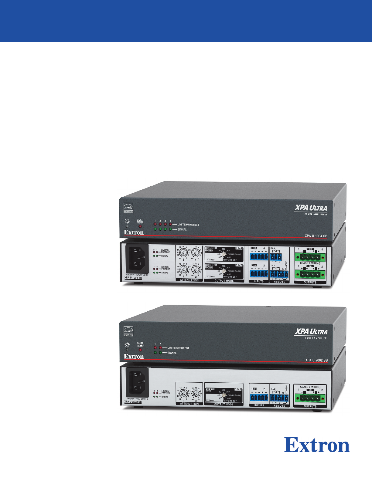
XPA U 1004 SB and
XPA U 2002 SB
Half-Rack Audio Power Amplifiers
User Guide
XPA Ultra Series
68‑3579‑01 Rev. A
02 21
Page 2
Safety Instructions
Safety Instructions • English
WARNING: This symbol, , when used on
the product, is intended to alert the user of the
presence of uninsulated dangerous voltage within
the product’s enclosure that may present a risk of
electric shock.
ATTENTION: This symbol, , when used on the
product, is intended to alert the user of important
operating and maintenance (servicing) instructions in
the literature provided with the equipment.
For information on safety guidelines, regulatory compliances, EMI/EMF
compatibility, accessibility, and related topics, see the Extron Safety and
Regulatory Compliance Guide, part number 68‑290‑01, on the Extron website,
www.extron.com.
Sicherheitsanweisungen • Deutsch
WARUNG: Dieses Symbol auf demProdukt soll
den Benutzer darauf aufmerksam machen, dass im
Inneren des Gehäuses dieses Produktes gefährliche
Spannungen herrschen, die nicht isoliert sind und
die einen elektrischen Schlag verursachen können.
VORSICHT: Dieses Symbol auf dem Produkt soll
dem Benutzer in der im Lieferumfang enthaltenen
Dokumentation besonders wichtige Hinweise zur
Bedienung und Wartung (Instandhaltung) geben.
Weitere Informationen über die Sicherheitsrichtlinien, Produkthandhabung,
EMI/EMF‑Kompatibilität, Zugänglichkeit und verwandte Themen finden Sie in den
Extron‑Richtlinien für Sicherheit und Handhabung (Artikelnummer
68‑290‑01) auf der Extron‑Website, www.extron.com.
Instructions de sécurité • Français
AVERTISSEMENT : Ce pictogramme, , lorsqu’il
est utilisé sur le produit, signale à l’utilisateur la
présence à l’intérieur du boîtier du produit d’une
tension électrique dangereuse susceptible de
provoquer un choc électrique.
ATTENTION : Ce pictogramme, , lorsqu’il
est utilisé sur le produit, signale à l’utilisateur
des instructions d’utilisation ou de maintenance
importantes qui se trouvent dans la documentation
fournie avec l’équipement.
Pour en savoir plus sur les règles de sécurité, la conformité à la réglementation,
la compatibilité EMI/EMF, l’accessibilité, et autres sujets connexes, lisez les
informations de sécurité et de conformité Extron, réf. 68‑290‑01, sur le site
Extron, www.extron.com.
Istruzioni di sicurezza • Italiano
AVVERTENZA: Il simbolo, , se usato sul prodotto,
serve ad avvertire l’utente della presenza di tensione
non isolata pericolosa all’interno del contenitore del
prodotto che può costituire un rischio di scosse
elettriche.
ATTENTZIONE: Il simbolo, , se usato sul
prodotto, serve ad avvertire l’utente della presenza
di importanti istruzioni di funzionamento e
manutenzione nella documentazione fornita con
l’apparecchio.
Instrucciones de seguridad • Español
ADVERTENCIA: Este símbolo, , cuando se utiliza
en el producto, avisa al usuario de la presencia
de voltaje peligroso sin aislar dentro del producto,
lo que puede representar un riesgo de descarga
eléctrica.
ATENCIÓN: Este símbolo, , cuando se utiliza
en el producto, avisa al usuario de la presencia de
importantes instrucciones de uso y mantenimiento
estas estan incluidas en la documentación
proporcionada con el equipo.
Para obtener información sobre directrices de seguridad, cumplimiento
de normativas, compatibilidad electromagnética, accesibilidad y temas
relacionados, consulte la Guía de cumplimiento de normativas y seguridad de
Extron, referencia 68‑290‑01, en el sitio Web de Extron, www.extron.com.
Per informazioni su parametri di sicurezza, conformità alle normative,
compatibilità EMI/EMF, accessibilità e argomenti simili, fare riferimento alla Guida
alla conformità normativa e di sicurezza di Extron, cod. articolo 68‑290‑01, sul
sito web di Extron, www.extron.com.
Instrukcje bezpieczeństwa • Polska
OSTRZEŻENIE: Ten symbol, , gdy używany na produkt, ma na celu
poinformować użytkownika o obecności izolowanego i niebezpiecznego
napięcia wewnątrz obudowy produktu, który może stanowić zagrożenie
porażenia prądem elektrycznym.
UWAGI: Ten symbol, , gdy używany na produkt, jest przeznaczony do
ostrzegania użytkownika ważne operacyjne oraz instrukcje konserwacji
(obsługi) w literaturze, wyposażone w sprzęt.
Informacji na temat wytycznych w sprawie bezpieczeństwa, regulacji wzajemnej
zgodności, zgodność EMI/EMF, dostępności i Tematy pokrewne, zobacz Extron
bezpieczeństwa i regulacyjnego zgodności przewodnik, część numer 68-290-01,
na stronie internetowej Extron, www.extron.com.
Page 3

Инструкция по технике безопасности • Русский
ПРЕДУПРЕЖДЕНИЕ: Данный символ, , если указан
на продукте, предупреждает пользователя о наличии
неизолированного опасного напряжения внутри корпуса
продукта, которое может привести к поражению электрическим
током.
ВНИМАНИЕ: Данный символ, , если указан на продукте,
предупреждает пользователя о наличии важных инструкций по
эксплуатации и обслуживанию в руководстве, прилагаемом к
данному оборудованию.
Для получения информации о правилах техники безопасности,
соблюдении нормативных требований, электромагнитной
совместимости (ЭМП/ЭДС), возможности доступа и других вопросах
см. руководство по безопасности и соблюдению нормативных
требований Extron на сайте Extron: , www.extron.com,
номер по каталогу - 68-290-01.
安全说明 • 简体中文
警告: 产品上的这个标志意在警告用户, 该产品机壳内有暴露的危险
电 压 ,有 触 电 危 险 。
注意: 产品上的这个标志意在提示用户, 设备随附的用户手册中有重
要的操作和维护(维修)说明。
关于我们产品的安全指南、遵循的规范、EMI/EMF 的兼容性、无障碍使
用的特性等相关内容,
敬请访问 Extron 网站 , www.extron.com,参见 Extron 安全规范指南,产品编号
68-290-01。
安全記事 • 繁體中文
警告: 若產品上使用此符號,是為了提醒使用者,產品機殼內存 在未隔離的危險
電壓,可能會導致觸電之風險。
注意 若產品上使用此符號,是為了提醒使用者,設備隨附的用戶手冊中有重要
的 操 作 和 維 護( 維 修 )説 明 。
有關安全性指導方針、法規遵守、EMI/EMF 相容性、存取範圍和相關主題的詳細資訊,
請瀏覽 Extron 網站:www.extron.com,然後參閱《Extron 安全性與法規遵守手
冊》,準則編號 68-290-01。
안전 지침 • 한국어
경고: 이 기호 가 제품에 사용될 경우, 제품의 인클로저 내에 있는
접지되지 않은 위험한 전류로 인해 사용자가 감전될 위험이 있음을
경고합니다.
주의: 이 기호 가 제품에 사용될 경우, 장비와 함께 제공된 책자에 나와
있는 주요 운영 및 유지보수(정비) 지침을 경고합니다.
안전 가이드라인, 규제 준수, EMI/EMF 호환성, 접근성, 그리고 관련 항목에 대한 자세한 내용은 Extron 웹 사이트(www.extron.com)의 Extron 안전 및 규제 준수 안내서, 68290-01 조항을 참조하십시오.
Copyright
© 2021 Extron. All rights reserved. www.extron.com
Trademarks
All trademarks mentioned in this guide are the properties of their respective owners.
The following registered trademarks (®), registered service marks (SM), and trademarks (TM) are the property of RGBSystems, Inc. or Extron (see the
current list of trademarks on the Terms of Use page at www.extron.com):
Registered Trademarks (
®
)
Extron, Cable Cubby, ControlScript, CrossPoint, DTP, eBUS, EDID Manager, EDID Minder, eLink, Flat Field, FlexOS, Glitch Free, GlobalConfigurator,
GlobalScripter, GlobalViewer, Hideaway, HyperLane, IPIntercom, IPLink, KeyMinder, LinkLicense, LockIt, MediaLink, MediaPort, NAV,
NetPA, PlenumVault, PoleVault, PowerCage, PURE3, Quantum, ShareLink, Show Me, SoundField, SpeedMount, SpeedSwitch, StudioStation,
SystemINTEGRATOR, TeamWork, TouchLink, V‑Lock, VideoLounge, VN‑Matrix, VoiceLift, WallVault, WindoWall, XPA, XTP, XTPSystems, and ZipClip
Registered Service Mark
(SM)
: S3 Service Support Solutions
Trademarks (™
)
AAP, AFL (Accu‑RATEFrameLock), ADSP(Advanced Digital Sync Processing), Auto‑Image, AVEdge, CableCover, CDRS(ClassD Ripple
Suppression), Codec Connect, DDSP(Digital Display Sync Processing), DMI (DynamicMotionInterpolation), DriverConfigurator, DSPConfigurator,
DSVP(Digital Sync Validation Processing), EQIP, Everlast, FastBite, Flex55, FOX, FOXBOX, IP Intercom HelpDesk, MAAP, MicroDigital, Opti‑Torque,
PendantConnect, ProDSP, QS‑FPC(QuickSwitch Front Panel Controller), RoomAgent, Scope‑Trigger, SIS, SimpleInstructionSet, Skew‑Free,
SpeedNav, Triple‑Action Switching, True4K, True8K, Vector™ 4K, WebShare, XTRA, and ZipCaddy
Page 4
FCC Class B Notice
This equipment has been tested and found to comply with the limits for a Class B digital
device, pursuant to part15 of the FCC rules. These limits provide reasonable protection
against harmful interference in a residential installation. This equipment generates, uses,
and can radiate radio frequency energy and, if not installed and used in accordance with
the instructions, may cause harmful interference to radio communications. There is no
guarantee that interference will not occur. If this equipment does cause interference to radio
or television reception, which can be determined by turning the equipment off and on, you
are encouraged to try to correct the interference by one or more of the following measures:
• Reorient or relocate the receiving antenna.
• Increase the separation between the equipment and receiver.
• Connect the equipment into an outlet on a circuit different from that to which the
• Consult the dealer or an experienced radio/TV technician for help.
In order to maintain compliance with FCC regulations, shielded cables must be used with
this equipment. Operation with non-approved equipment or unshielded cables is likely to
result in interference to radio and TV reception. The user is cautioned that changes and
modifications made to the equipment without the approval of the manufacturer could void
the user’s authority to operate this equipment.
NOTE: This device complies with part 15 of the FCC rules. Operation is subject to the
following two conditions: (1) This device may not cause harmful interference, and (2)
This device must accept any interference received, including interference that may
cause undesired operation.
receiver is connected.
NOTE: For more information on safety guidelines, regulatory compliances, EMI/EMF
compatibility, accessibility, and related topics see the Extron Safety and Regulatory
Compliance Guide on the Extron website.
Page 5
Conventions Used in this Guide
Notifications
The following notifications are used in this guide:
CAUTION: Risk of minor personal injury.
ATTENTION : Risque de blessuremineure.
ATTENTION: Risk of property damage.
Risque de dommages matériels.
NOTE: A note draws attention to important information.
TIP: A tip provides a suggestion to make working with the application easier.
Specifications Availability
Product specifications are available on the Extron website, www.extron.com.
Extron Glossary of Terms
A glossary of terms is available at http://www.extron.com/technology/glossary.aspx.
Page 6

Contents
Introduction ................................................1
About this Guide .................................................. 1
Features .............................................................. 2
Installation .................................................. 4
Mounting the XPA Ultra Series Amplifier ............... 4
Tabletop Use ................................................... 5
UL Rack Mounting Guidelines .......................... 6
Rack Mounting ................................................ 5
Rack Ear Mounting .......................................... 5
Bridge Plate Rack Mounting ............................ 6
Rack Shelf Mounting........................................ 7
Flexible Conduit Adapter Kit Installation ............... 8
Operation..................................................12
Front Panel Features .......................................... 12
Rear Panel Features .......................................... 13
Remote Standby Port ........................................ 17
Troubleshooting ........................................ 17
Amplifier Fails to Exit Standby Mode Promptly ... 17
Amplifier Enters Standby Mode Too Early .......... 19
Limiter/Protect LED Warning Indicators ............. 19
Over Temp Indicator LED ................................... 19
Extron Warranty ........................................20
viXPA U 1004 SB and XPA U 2002 SB • Table of Contents
Page 7

Page 8

Introduction
This section gives an overview of the Extron XPA Ultra Series: XPA U 1004 SB and XPA U
2002 SB Half-Rack Four-Channel/Two-Channel audio power amplifiers. Topics include:
• About this Guide
• About the XPA U 1004 SB and XPA U 2002 SB
• Features
About this Guide
This guide describes the XPA U 1004 SB and XPA U 2002 SB Half Rack Four-Channel/TwoChannel audio power amplifiers and discusses how to install, configure, and operate them.
In this guide, the terms “unit”, “amplifier”, and “power amplifier” refer to the
XPA U 1004 SB and XPA U 2002 SB.
About the XPA U 1004 SB and XPA U 2002 SB
The Extron XPA U 1004 SB and XPA U 2002 SB are ENERGY STAR qualified four- and
two-channel audio power amplifiers with flexible channel pairs that can drive 8 ohm, 4 ohm,
70volt, or 100 volt loads. The XPA U 1004 SB’s two individually bridgeable pairs can deliver
two 100 watt channels into low-impedance systems or one 200 watt channel into low- or
high-impedance systems. The XPA U 2002 SB’s bridgeable output pair can deliver two
200 watt channels into low-impedance systems or one 400 watt channel into low- or highimpedance systems.
Output mode selection is made via a rear panel rotary switch for quick and easy setup.
The convection-cooled, plenum-rated enclosures of the XPA U 1004 SB and XPA U 2002
SB don’t require empty rack spaces for ventilation and include rack mount hardware. They
feature a highly efficient advanced Class D amplifier design with defeatable auto standby,
fast wake up from standby, and patented Extron CDRS (Class D Ripple Suppression)
technology. Remote volume and mute control is possible per channel pair from Extron VCM,
VC, and select MediaLink controllers.
XPA U 1004 SB and XPA U 2002 SB • Introduction 1
Page 9

Features
• Selectable output modes per channel pair:
• XPA U 1004 SB
• Two 100 watt channels into 8 ohms or 4 ohms
• One 200 watt bridged channel into 70V or 100V, with or without HPF
• One 200 watt bridged channel into 8 ohms or 16 ohms
• — Allows this amplifier model to be used in a wide variety of system configurations
• XPA U 2002 SB
• Two 200 watt channels into 8 ohms or 4 ohms
• One 400 watt bridged channel into 70V or 100V, with or without HPF
• One 400 watt bridged channel into 8 ohms or 16 ohms
• — Allows this amplifier model to be used in a wide variety of system configurations
• ENERGY STAR
®
qualified amplifiers — The XPA U 1004 SB and the XPA U 2002 SB
are ENERGY STAR qualified and energy efficient amplifiers, conserving energy and reducing
costs.
• Extron Patented CDRS (Class D Ripple Suppression) Technology — CDRS is an
Extron pantented technology providing a smooth and clean audio waveform, and improving
signal fidelity over Class D amplifier designs.
• CDRS eliminates the high frequency switching ripple characteristics of Class D
amplifiers, a source of RF emissions which can interfere with sensitive AV equipment
like wireless mircophones.
• Convection cooled and fanless operation ‑ can be stacked without extra rack space for
• ventilation — The XPA U 1004 SB and the XPA U 2002 SB do not have internal fans or
vents for cooling, ensuring quiet reliable operation. The units generate substantially less
heat than conventional power amplifiers, making the XPA Ultra Series ideal for rack-mount
applications where space is limited.
• See Rack Mounting Ventilation Recommendations on page7.
• Defeatable auto-standby with fast wake up — The amplifiers meet ENERGY STAR
qualification requirements with an auto-standby feature that automatically places the
units into standby after 25 minutes of in activity; thereby dramatically reducing power
consumption. The XPA U 1004 SB and XPA U 2002 SB quickly return to full power in less
100 ms upon signal detection, with minimal inrush current. Auto-standby can be disabled if
required.
• UL 2043 Plenum rated when used with the optional Flexible Conduit Adapter Kit/
AV equipment — The XPA U 1004 SB and XPA U 2002 SB amplifiers meet UL 2043
when installed with the Flexible Conduit Adapter Kit, part # 70-228-02. The amplifiers must
meet this requirement for heat and smoke release for installation within a plenum airspace.
Above-the-ceiling placement conceals the amplifier to prevent theft, and it is convenient for
installing when space inside the room is limited.
• Remote volume and mute control per channel pair — With Extron VCM, VC, and
select MediaLink controllers.
• All rated watts are usable with all channels driven — With a XPA Ultra, designs can
utilize 100% of the rated power.
• Professional grade signal-to-noise and THD+N performance — The XPA U 1004 SB
and the XPA U 2002 SB both deliver professional grade performance, featuring 100 dB
signal-to-noise ratio and THD+N of less than 0.1%.
XPA U 1004 SB and XPA U 2002 SB • Introduction 2
Page 10

• Ultra low inrush current at power up - no need for power sequencing — Allows
multiple XPA Ultra amplifier to be powered on simultaneously without overloading power
circuits. This eliminates the need for power sequencing.
• Power factor correction - removes harmonic content on AC line — The XPA U
1004 SB and XPA U 2002 SB features power factor correction technology that smooths
out the high peak currents of the amplifier’s current draw, minimizing the presence of
high frequency harmonics on the AC power line, preventing audible artifacts from being
transmitted to other audio equipment in the system.
• Rear panel recessed, detented level controls — Provides attenuation of input signal
for adjusting audio system gain staging. These controls are lcoated on the rear panel to
prevent tampering with the level adjustments. Laser etched markings provide enhanced
visibility of settings for ease of configuration.
• Remote standby port — Enables the XPA U 1004 SB and XPA U 2002 SB to be
remotely powered down when not in use, reducing operating cost.
• Automatic clip limiter — Detects actual onset of clipping. Gain is automatically
reduced without audible artifacts to prevent clipping distortion.
• Multiple protection circuits — Activate during output shorts, thermal overload, or DC
faults to prevent damage to the amplifier and speakers.
• 5 mm screw-lock captive screw speaker connectors — Enable simple, secure
connections with 22 to 12 AWG speaker cables.
• Front and rear-mounted signal and protection indication LEDs — Provide
convenient indication of input signal presence and protection circuit activation from both
sides of an equipment rack.
• Front panel over-temperature LED — Provides visual indication that the amplifier’s
temperature has exceeded the optimal value, well in advance of the onset of thermal
protection circuitry.
• Internal Extron Everlast
™
power supply — Provides worldwide power compatibility,
with high-demonstrated reliability and low power consumption for reduced operating
cost.
• Extron Everlast Power Supply is covered by a 7-year parts and labor warranty.
XPA U 1004 SB and XPA U 2002 SB • Introduction 3
Page 11

Installation
This section describes the installation and setup of the XPA U 1004 SB and XPA U 2002 SB.
Topics include:
• Mounting the XPA Ultra Series Amplifiers
• Flexible Conduit Adapter Kit Installation
Mounting the XPA Ultra Series Amplifiers
The XPA U 1004 SB and XPA U 2002 SB can be mounted in a rack using rack ears,
mounted on a rack shelf, set on a table, or mounted in the plenum space above a ceilingmounted projector. Also, two amplifiers can be connected using the bridging plate to create
a full rack-width unit.
This guide uses images of the XPA U 1004 SB to describe installation, but both amplifiers
are installed the same way.
Tabletop Use
Four self-adhesive rubber are included. Attach one foot at each corner on the bottom side
of the amplifier and place the unit in a desired location.
UL Rack Mounting Guidelines
The following Underwriters Laboratories (UL) guidelines pertain to the safe installation of the
equipment in a rack.
• Elevated operating ambient temperature — If the equipment is installed in a closed
or multi-unit rack assembly, the operating ambient temperature of the rack environment
may be greater than room ambient temperature. Therefore, install the equipment in an
environment compatible with the maximum ambient temperature (TMA = +32° F to
+122° F (0° C to +50° C)/ 10% to 90%, noncondensing) specified by Extron.
• Reduced air flow — Install the equipment in a rack so the amount of air flow required
for safe operation of the equipment is not compromised.
• Mechanical loading — When mounting the equipment in the rack, ensure uneven
mechanical loading does not cause a hazardous condition.
• Circuit overloading — When connecting the equipment to the supply circuit, consider
the effect circuit overloading might have on overcurrent protection and supply wiring.
Consider equipment nameplate ratings when addressing this concern.
• Reliable earthing (grounding) — Maintain reliable grounding of rack-mounted
equipment. Pay particular attention to supply connections other than direct connections
to the branch circuit (for example, use of power strips).
XPA U 1004 SB and XPA U 2002 SB • Installation 44
Page 12

Rack Mounting
The XPA U 1004 SB and XPA U 2002 SB can both be mounted onto a rack using one of
the following methods.
Rack Ear Mounting
The XPA U 1004 SB and XPA U 2002 SB ship with a set of rack ears, so that the half rack-
width amplifiers can be installed in a full rack-width space.
Mount the amplifier with the rack ears by doing the following:
1. Remove the rubber feet from the bottom of the amplifier if previously installed.
2. Attach the included rack ears to the sides of the amplifier with the four provided #6
3. Insert the amplifier into the rack and align the holes in the rack ear with the holes on the
4. Secure the amplifier to the rack using four provided 10-32 x 3/4” screws (see figure 2,
machines screws (1).
1
OV
ER
TEMP
e
1 2 3 4
LIMITER/PROTECT
SIGNAL
POWER A
MPLIFIER
S
XPA U
100
4 SB
Figure 1. Installing XPA Ultra Rack Ears
rack.
).
2
2
OVER
TEMP
e
1 2 3
4
L
IMITER/PR
SIGN
OTEC
AL
T
PO
WE
R
A
MP
L
I
FIER
S
XP
A
U
100
4 SB
Figure 2. Secure XPA Ultra Amplifier to Rack
Bridge Plate Rack Mounting
The XPA U 1004 SB and XPA U 2002 SB ships with a bridge plate connector to allow two
amplifiers to be connected together and form a full rack-width unit.
Mount two XPA Ultra Series amplifiers by doing the following:
1. If the rubber feet are installed on the bottom of the amplifier, remove them.
2. Position two amplifiers upside down and next to each other.
3. Use the bridge plate connector and the four provided #4 machine screws to connect
the two amplifiers together (see figure 3, 1).
4. Attach the two short rack ears to the amplifiers with four provided #6 machine screws
(2).
XPA U 1004 SB and XPA U 2002 SB • Installation 5
Page 13

Mounting
screws (4)
XPA U 1004 SB
POWER AMPLIFIERS
SIGNAL
LIMITER/PROTECT
1 2 3 4
e
TEMP
OVER
XPA U 1004 SB
POWER AMPLIFIERS
1
SIGNAL
LIMITER/PROTECT
1 2 3 4
2
e
TEMP
OVER
Figure 3. Installing XPA Ultra Series Bridge Plate
5. Insert the amplifiers into the rack and align the holes in the rack ears with the holes in
the rack.
6. Secure the amplifiers to the rack using four provided 10-32 3/4” screws (see figure 4,
)
3
3
OVER
TEMP
e
1 2 3 4
LIMITER/PROTECT
SIGNAL
POWER AMPLIFIERS
XPA U 1004 SB
OVER
TEMP
e
1 2 3 4
LIMITER/PROTECT
SIGNAL
POWER AMPLIFIERS
XPA U 1004 SB
Figure 4. Secure Connected XPA Ultra Amplifiers to Rack
Rack Shelf Mounting
The XPA U 1004 SB and XPA U 2002 SB can both be mounted in a shelf using the optional
RSU 129 1U Universal Rack Shelf Kit.
Mount the amplifier with the shelf as follows:
1. If the rubber feet are installed on the bottom of the amplifier, remove them.
2. Place the amplifier on one half of the rack shelf.
3. Align the front of the amplifier with the front of the shelf, and align the threaded holes on
the bottom of the amplifier with the holes in the rack shelf.
4. Attach the amplifier to the rack shelf with the two provided 4-40 x 3/16” machine
screws. Fasten them into diagonally opposite corners by inserting the screws from the
underside of the shelf.
5. Either attach the false front panel, which is provided with the rack shelf, to the
unoccupied side of the rack, or install a second half rack-width device to that side.
Repeat steps 1 through 5 if a second device is being installed.
XPA U 1004 SB and XPA U 2002 SB • Installation 6
Page 14

6. Attach the rack to the shelf by using the four 10-32 x 3/4” screws provided with the
shelf. Insert the screws through #10 beveled washers, then through the holes in the
rack (see Figure 5, below).
RSU 129
1U Universal Rack Shelf
False faceplate
uses 2 screws.
OVER
TEM
P
e
1
2
3 4
LI
M
I
TE
R
/PROTECT
SIG
N
AL
P
OWE
R
A
M
P
LI
FI
E
RS
4
S
E
RIES
Use 2 mounting holes
on opposite corners.
X
P
A
U
1
00
Figure 5. Mounting the Amplifier onto a Rack Shelf
ATTENTION:
• Using screws longer than 3/16” will damage the unit and void the warranty.
• L’utilisation de vis plus longues que 3/16” endommagera l’unité et annulera la
garantie.
Rack Mounting Ventilation Recommendations
Excessive heat decreases the optimal lifetime of the power amplifier. An Over Temp indicator
LED on the front panel of the amplifier lights red whenever the recommended operating
temperature has been exceeded.
The XPA Ultra amplifiers need to be arranged in a rack environment, so that the environment
around the amplifier does not reach or go beyond +122 °F (+50 °C). No more than four
amplifiers should be stacked vertically without an open space in between, as seen in figure
6.
(2) 4-40 x 3/16"
Screws
Vent Space
Vent Space
Vent Space
Vent Space
Vent Space
Vent Space
Vent Space
Figure 6. Vent Space Example
The XPA Ultra amplifiers can be arranged above or below another non-XPA Ultra device. The
environment around the amplifier should still not reach or go beyond +122 °F (+50 °C).
XPA U 1004 SB and XPA U 2002 SB • Installation 7
Page 15

Flexible Conduit Adapter Kit Installation
WARNING :
AVERTISSEMENT :
• The circuit breaker used for this connection should be rated no lower than 20 amps and no
greater than 30 amps.
• Le disjoncteur utilisé pour cette connexion devrait avoir une cote comprise entre 20 et
30 amps.
• This unit must be installed in accordance with the National Electrical Code and with all
local codes.
• Cet appareil doit être installé conformément au National Electrical Code et à tous les
codes locaux.
• An ALL-POLE MAINS SWITCH with a contact separation of at least 3 mm in each
pole shall be incorporated in the electrical installation of the building, The installation
shall be carried out in accordance with all applicable installation rules.
• Un interrupteur omnipolaire avec une séparation contact d’au moins 3 mm dans
chaque pôle, devra être incorporée dans l’installation électrique du bâtiment.
L’installation doit être réalisée conformément à toutes les règles d’installation
applicables.
• Installation and service must be performed by a qualified electrician only.
• L’installation et l’entretien doivent être effectués uniquement par un électricien qualifié.
• Make sure the source device and the XPA are turned off and disconnected from the
power source before you begin.
• Vérifiez que l’appareil source et le périphérique source sont éteints et déconnectés de
la source d’alimentation avant de commencer.
• To reduce the risk of fire or electric shock, do not expose this apparatus to rain or
moisture.
• Afin de réduire les risques d’incendie ou de choc électrique, protégez cet appareil de
la pluie ou de l’humidité.
• The product is a Class I product, which must be connected only to a mains socket
outlet with a protective earthing (grounding) connection.
• Ce produit est un produit de Classe I, qui doit être connecté seulement à une prise
femelle secteur équipée d’une connexion de mise à la terre.
• The mains plug/appliance coupler is used as the disconnect device and shall remain
readily operable.
• La fiche secteur / le coupleur d’appareil est utilisé comme dispositif de déconnexion et
doit rester facilement utilisable.
ATTENTION:
• A UL-Listed electrical distribution box is recommended for the termination of
the conduit opposite the PS 124 power supply or the XPA amplifier. See UL
Requirements below.
• Un boîtier de distribution électrique certifié UL est recommandé pour la terminaison du conduit à
l’opposé de l’alimentation PS 124 ou de l’amplificateur XPA. Voir “UL Requirements” on page
9.
The optional Flexible Conduit Adapter Kit includes the following parts:
• One conduit adapter plate (pre-attached), for PS 124 and XPA Series amplifiers
• One conduit adapter plate for XPA Ultra Series and NetPA Ultra Series amplifiers
(not attached)
XPA U 1004 SB and XPA U 2002 SB • Installation 8
Page 16

• One 6 foot long electrical conduit
Remove (8)
Slide cover forward and
• Three 7.5 foot, 18-gauge power wires with spade connectors
• Three auxiliary crimp-style spade connectors designed for 14- to 16-gauge wires
• One UL-rated zip tie wrap
The kit provides a way to replace the IEC power cord with a conduit, where required by
local codes.
NOTE: If needed, Extron recommends using a UL-rated crimp tool to terminate the spade
connectors. One recommended choice is the Molex crimp tool.
UL Requirements
The Underwriters Laboratories (UL) requirements listed below pertain to the installation
of the flexible conduit onto an XPA U 1004 SB and XPA U 2002 SB.
• This unit must not be used beyond its rated voltage range.
• This unit must be wired to a UL-Listed distribution box.
NOTE: The UL-approved electrical distribution box is not included with either the XPA
Ultra or the Flexible Conduit Adapter Kit. The installer is responsible for obtaining and
installing the box.
Installing the Flexible Conduit Adapter Kit
WARNING: Electrostatic discharge (ESD) can damage IC chips even though you cannot feel
it. You must be electrically grounded before touching anything inside the XPA. A grounding
wrist strap is recommended.
AVERTISSEMENT : Les décharges électrostatiques peuvent endommager les puces de circuit
même si vous ne pouvez pas les sentir. Vous devez être électriquement relié à la terre avant
de toucher un élément à l’intérieur du XPA. Un braceletde mise à la terreest recommandé.
Install the flexible conduit to the XPA Ultra Amplifier as follows:
1. Unplug the IEC power cord from the amplifier.
2. Remove the 8 screws from the top, sides, and bottom of the amplifier then slide and lift
the cover off.
lift straight up.
screws
BR
3 4
2
BR
CLASS 2 WIRING
3&4
1
4
)
GC
BR
(
3
STANDBY
V
G
1&2
&4
3
100-240V
XPA U 1004 SB
BRIDGED
MONO
8
10
6
12
4
8
2
14
STEREO
10
6
12
4
0
2
BRIDGED
14
4
∞
MONO
18
8
0
10
6
26
12
4
3
∞
LIMITER/
8
2
14
10
STEREO
6
PROTECT
12
3 4
4
0
SIGNAL
2
14
2
∞
18
0
26
1
∞
LIMITER/
PROTECT
2
ATTENUATION
1
SIGNAL
--A, 50-60 Hz
8Ω
8Ω
OUTPUT MODE
2
)
GCV
BR
70V HPF OFF )
(
1
100V
70V
8Ω
8Ω/4Ω
70V
8Ω
8Ω/4Ω
REMOTE OUTPUTS
100V (HP F O FF)
&2
1
INPUTS
70V HPF OFF )
100V
100V (HP F O FF)
Figure 7. Removing the Cover
XPA U 1004 SB and XPA U 2002 SB • Installation 9
Page 17

3. Remove the two screws holding the blue hot line and the brown neutral wires from the
Disconnect cables
and r
connector
e
Washer-B
Place the adapter plate
terminal block on the PCB. Put the screws to the side to be used later (see figure 8 on
page10).
4. Remove the ground wire nut from the grounding stud located on the bottom of the
enclosure as shown in figure 8, below. Place the nut with the other screws to be used
later.
5. Remove the wires attached to the IEC connector from the body of the amplifier, and
slide the IEC connector and wire up and out of the amplifier’s enclosure (see figure 8,
below).
emove IEC
.
Blue Wire
Brown Wir
Remove nut
Figure 8. Removing the IEC Connector
6. Remove the washer at the end of the conduit (see Washer-B in figure 9), and remove
the conduit adapter plate that ships attached to the conduit.
Separate adapter plate
and washer from conduit
Conduit Adapter Plate
Washer-A
Figure 9. Removing the Existing Adapter Plate
7. Place the adapter plate that ships with the conduit kit on the conduit itself with the flat
side of the plate facing the hexgonal nut, and secure the new plate to the conduit with
the washer that was removed in step 6 (see figure 10).
with the flat side against
washer-A and secure with
Washer-B
NetPA Ultra Series Conduit
Adapter Plate
Washer-A
washer-B.
Figure 10. Secure XPA Ultra Series Adapter Plate to Conduit
8. Thread the blue, brown, and green 18-gauge power wires that are included with the
flexible conduit adapter kit through the length of the electrical conduit.
XPA U 1004 SB and XPA U 2002 SB • Installation 10
Page 18

9. Install the conduit with the new conduit plate attached into the opening from where the
Tie Wrap
IEC connector removed in step 5 (see figure 8 on page10).
10. Connect the blue hot (line) and the brown neutral wires to the terminal block on the PCB
using the two screws removed back in step 3. Use the included zip tie wrap to secure
the two wires together close to the terminals (see figure 11).
WARNING: Ensure that you observe correct wire polarity. The following illustration
shows the location of the hot (line) and neutral terminals.
AVERTISSEMENT : Respecter la polarité correcte des câble. L’illustration suivante
indique l’emplacement des bornes de ligne et de neutre.
Blue Wire
Slide IEC
connector
plate and
conduit into
enclosue.
100-240V 1.3A
50-60Hz
L
N
Grounding Nut
Brown Wire
Figure 11. Install the Conduit Assembly
11. Connect the ground wire, as shown in figure 13 above, to the grounding stud located
on the bottom of the enclosure using the nut removed in step 4. Remove the ground
wire nut from the grounding stud located on the bottom of the enclosure as shown in
figure 11, above. Place the nut with the other screws to be used later.
12. Replace the cover of the XPA Ultra amplifier by reattaching the eight screws removed in
step 2. Remove the 8 screws from the top, sides, and bottom of the amplifier then slide
and lift the cover off.
XPA U 1004 SB and XPA U 2002 SB • Installation 11
Page 19

Operation
This section describes the installation and setup of the XPA U 1004 SB and XPA U 2002 SB.
Topics include:
• Front Panel Features
• Rear Panel Features
• Troubleshooting
Front Panel Features
A
B
OVER
TEMP
e
B
A
OVER
TEMP
e
Power/Standby Indicator
A
C
1234
C
12
LIMITER/PROTECT
SIGNAL
LIMITER/PROTECT
SIGNAL
Over Temp Indicator
B
POWER AMPLIFIERS
XPA U 1004 SB
POWER AMPLIFIERS
XPA U 2002 SB
Channel Status LEDs
C
Figure 12. XPA U 1004 SB and XPA U 2002 SB Front Panels
Power/Standby LED — A single LED that lights green when the unit is on and active,
A
and lights amber when:
• The unit is in standby mode, which turns off all outputs from the amplifier although
the amplifier still receives power.
• The unit will not come out of standby when DC voltage is detected. The amplifier
only comes out of standby mode by either resetting the device or powering it down.
NOTE: Power indicator LED may stay lit amber for a short time after removing the AC
Power Supply. This is normal.
Over Temp Indicator — A single LED that lights red when the amplifier has exceeded
B
the maximum recommended operating temperature. The amplifier recovers once the
unit has cooled down to below the maximum recommended operating temperature.
Power limiting may occur, but it depends on the unit’s temperature.
XPA U 1004 SB and XPA U 2002 SB • Installation 1212
Page 20

Channel Status LEDs — (see figure 12 on page12) Two rows of LEDs that
34
C
represent the amplifier’s channels.
• Limiter/Protect LED — The LEDs lights red when the channel is in protection
• Signal LED — The LEDs light green when the input signal is detected.
NOTE: The LEDs are also located on the rear panel.
Rear Panel Features
mode, which is triggered by any of the limiter protection circuits such as:
• When the clip limiter is activiated due to excessive clipping.
• When the output short circuits.
A
--A, 50-60 Hz
100-240V
XPA U 1004 SB
A
--A, 50-60 Hz
100-240V
XPA U 2002 SB
Removable IEC
A
Power Receptacle
E
Line Input
B
B
1
34
1
2
2
LIMITER/
PROTECT
SIGNAL
LIMITER/
PROTECT
SIGNAL
LIMITER/
PROTECT
SIGNAL
C
10
10
8
12
12
8
14
18
26
0
∞
10
12
8
14
18
26
0
∞
1
ATTENUATION OUTPUT MODE
C
10
12
8
6
14
18
4
26
2
0
∞
ATTENUATION OUTPUT MODE
B
F
BRIDGED
6
14
6
4
4
2
2
0
∞
43
10
12
8
6
14
6
4
4
2
2
0
∞
2
MONO
STEREO
BRIDGED
MONO
STEREO
8Ω
8Ω
4Ω
8Ω
8Ω
4Ω
D
10
12
8
BRIDGED
6
14
4
2
0
∞
21
Channel Status
LEDs
Speaker Output
Connectors
MONO
STEREO
8Ω
8Ω
4Ω
D
16Ω
70V
70V (HPF OFF)
100V
100V (HPF OFF)
16Ω
70V
70V (HPF OFF)
100V
100V (HPF OFF)
16Ω
70V
70V (HPF OFF)
100V
100V (HPF OFF)
1
&2
1
&2
1
&2
1
Attenuators
C
Remote Ports
G
BR
(
3
BR
(
1
INPUTS
E
BR
(
)
INPUTS
E
3&4
)
4
V
1&2
)
2
REMOTEOUTPUTS
G
1&2
2
REMOTEOUTPUTS
Figure 13. XPA U 1004 SB and XPA U 2002 SB Rear Panels
G
GCV
GC
GCV
STANDBY
G
G
CLASS 2 WIRING
1
STANDBY
CLASS 2 WIRING
1
Output Mode
D
Selector Switches
F
BR
BR
F
BR
2
2
Removable IEC Power Receptacle — Connect the supplied IEC power cord here
A
for power input (100 VAC to 240 VAC, 50-60 Hz) to the internal power supply. The
connector can be replaced by a Flexible Conduit Adapter Kit (see Flexible Conduit
Adapter Kit Installation on page8).
Channel Status LEDs — The 1004 SB has four double-stacked LEDs, while the 2002
B
SB has two double-stacked LEDs.
The top red LEDs indicate limiter/protect status, and the bottom green LEDs indicate
signal status. These LEDs share the same function as the front panel LEDs.
Attenuators — Use a small screwdriver to adjust the gain structure for a corresponding
C
channel. Each channel has its own potentiometer, ranging from ∞ (full attenuation) to 0
dB (no attenuation)
To adjust the attenuation level on the amplifier, perform the following:
When volume is controlled at the source:
1. If connecting to a source device with volume control (variable output), ensure the
volume on the source device is set to its lowest point, then adjust the attenuation of
the amplifier fully counterclockwise.
XPA U 1004 SB and XPA U 2002 SB • Operation 13
Page 21

2. Set the source device volume to the maximum level. No sound should come out.
Stereo 8Ω or 4Ω Output Modes
Bridged Mono 8Ω/16Ω/70V/100V Modes
or 100V Speaker Loads
3. Raise the attenuation on the XPA Ultra Series amplifier until sound distortion occurs,
then lower the attenuation level slowly until distortion disappears. This setting
ensures no clipping occurs, whatever the source device volume setting is.
NOTE: When setting volume control through a source device, make sure the
device’s volume is set to variable out. Consult the device’s user manual for
detailed instructions on its calibration.
When volume is controlled at the amplifier:
1. If volume will be controlled at the amplifier using a remote volume control
(see section G for details), ensure the volume on the source device is set to its
lowest point, then adjust the attenuation of the amplifier fully counterclockwise.
2. Set the source device’s volume to its maximum level.
3. Set the remote volume control to its maximum level. No sound should come out.
4. Raise the attenuation on the XPA Ultra Series amplifier until sound distortion occurs,
then lower the attenuation level slowly until distortion disappears. This setting
ensures no clipping occurs, whatever the source device volume setting is.
NOTE: When volume will be controlled at the amplifier using a remote volume
control, make sure the source device’s audio output is set to fixed out (local
volume control is disabled). Consult the device’s user manual for detailed
instructions on its calibration.
Use both CH 1 and CH 2
Attenuators (set
levels independently)
--A, 50-60 Hz
100-240V
XPA U 2002 SB
Tip
Ring
Sleeves
Tip
Ring
Stereo
Balanced Input
Use CH 1 Attenuator to
set level for bridged
output (CH 2 is ignored)
--A, 50-60 Hz
100-240V
XPA U 2002 SB
Tip
Ring
Sleeves
Set Output Mode to
appropriate stereo
setting (8Ω or 4Ω)
10
10
12
8
12
8
BRIDGED
16Ω
6
14
6
14
1
2
LIMITER/
18
4
PROTECT
26
2
SIGNAL
0
∞
ATTENUATION OUTPUT MODE
Tip
Sleeves
Tip
Stereo
Unbalanced Input
Set Output Mode to appropriate
bridged mono setting (8Ω,16Ω,
70V, 100V). Use HPF OFF only
if HPF present in upstream DSP.
10
12
8
14
1
2
LIMITER/
18
PROTECT
26
SIGNAL
∞
ATTENUATIONOUTPUT MODE
Mono
Balanced Input
8Ω
MONO
4
8Ω
2
4Ω
0
∞
STEREO
21
10
12
8
BRIDGED
6
14
6
4
2
0
8Ω
MONO
4
8Ω
2
4Ω
0
∞
STEREO
21
Tip
Sleeves
Wire CH 1 and CH 2
input connector based
on source as shown below
1&2
BR
(
)
1
&2
1
Ring
Sleeves
1
&2
70V (HPF OFF)
2
INPUTS
Tip
Dual Mono
Balanced Input
Wire CH 1 input
connector based on
source as shown below
BR
(
)
1
2
INPUTS
REMOTE OUTPUTS
1&2
70V
70V (HPF OFF)
100V
100V (HPF OFF)
16Ω
70V
100V
100V (HPF OFF)
Mono
Unbalanced Input
Wire output connector
to speaker loads as
shown to the right
CLASS 2 WIRING
STANDBY
BR
1
G
GCV
Sleeves
CLASS 2 WIRING
STANDBY
1
G
GCV
REMOTE OUTPUTS
Do not tin
the wires!
3
"
(5 mm) MAX.
16
2
Tip
Dual Mono
Unbalanced Input
Wire output connector
to mono speaker load
as shown to the right
BR
2
Stereo 8Ω or 4Ω
Speaker Loads
CH 2
CH 1
Do not tin
the wires!
3
"
(5 mm) MAX.
16
Mono 8Ω, 16Ω, 70V,
CH 1
Figure 14. XPA SB Configuration Based on Output Mode
XPA U 1004 SB and XPA U 2002 SB • Operation 14
Page 22

NOTE: XPA U 2002 SB shown. Channels 3 and 4 of the XPA U 1004 SB are
configured in the same way.
Output Mode Selector Switches — (see figure 14 on
D
page14) Each channel features a 8-position rotary switch
to set the output mode for specific channels (see figure on
the right). The bottom switch controls channels 1 and 2,
and the XPA U 1004 SB has a top switch that controls
BRIDGED
MONO
STEREO
OUTPUT MODE
16Ω
8Ω
8Ω
4Ω
100V (HPF OFF)
70V
70V (HPF OFF)
100V
channels 3 and 4. There are eight settings that are divided
into stereo and bridged mono:
• Stereo Mode (4 ohm/8 ohm) — Each channel of a output pair behaves
independently, and each input is routed to its respective output. A channel’s level is
set by its dedicated attenuator.
• Bridged Mono Modes — There are six bridged mono modes: two low-impedance
(8 ohm and 16 ohm bridged) and four high-impedance (70V, 70V with no HPF,
100V, and 100V with no HPF)
In all six mono modes, the outputs of a pair are bridged, and the lowest-numbered
channel is fed to the pair’s positive pins. The bridged output’s positive pin is now
the lowest-numbered channel’s pin. And the higher-numbered output’s positive pin
becomes the bridged output’s negative pin.
The level is set by using the attenuator on the lowest-numbered channel. The
higher-numbered channel’s input and attenuator are not used in bridged mono
mode.
In either 70V or 100V modes, an 80 Hz, 12 dB/octave high-pass filter is applied
to the signal. This can be disabled by selecting (HPF OFF) for either 70V or 100V
mode. On 8 ohm and 16 ohm bridged modes, the filter is disabled.
1
& 2
NOTE: In 70V/100V output modes, HPF should be disabled at the amplifier
only if a high-pass filter will be applied upstream of the amplifier.
Line Input — (see figure 14 on page14) Wire the amplifier input connectors based
E
on the output. See Figure 16 for details on how to wire the input connectors.
NOTE: In bridged mono output modes, even-numbered channels are not used in
the connector.
Speaker Output Connectors — (see figure 14 on page14)
F
Connect up to two 4-pin, 5mm captive screw connectors for up to
four channels of speaker outputs. Each port has a screw flange to
secure the plug to the connector. Observe the correct polarities for
each channel as shown to the right.
XPA U 1004 SB and XPA U 2002 SB • Operation 15
Page 23

WARNING:
Resistor
AVERTISSEMENT :
• Do not tie channel output pins to each other or to ground. Doing so will short
out the outputs, damage the amplifier, or both.
• Ne pas lier les sorties 1 et 2 des canaux entre elles ou à la terre. Les sorties
pourraient être court-circuitées et/ou l’amplificateur pourrait être endommagé.
• To avoid risk of damage to the amplifier or the speakers, always connect low
impedance speaker loads (8Ω/4Ω) and high-impedance speaker loads (70V)
to the appropriately marked output connectors on the amplifier.
• Pour éviter tout risque de détérioration de l’amplificateur ou des enceintes,
connectez toujours les charges de l’enceinte faible impédance (8 Ω/ 4 Ω) et
les charges de l’enceinte haute impédance (70 V) aux connecteurs de sortie
correctement identifiés sur l’amplificateur.
NOTE: You must use Class 2 wiring for this output to comply with UL requirements.
To wire the stereo audio output, do the
following steps:
1. Strip and insert the speaker wires into the
connector and tighten the captive screws.
Make sure to observe correct polarity.
Do not tin the wires!
2. Insert the wired connector into the amplifier output,
and secure the plug by tightening the screws on
either side..
G Remote Ports — (see figure 14 on page14) On the XPA U 1004 SB, connect a
3-pole, 3.5mm captive screw connector for remote volume control on channels three
and four. On both amplifiers, there is a 5-pole captive screw port. The bottom port use
a 3-pin captive screw plug for volume control of channels 1 and 2 on the V, C, and G
pins, and a 2-pin captive screw for standby on the STANDBY and G pins.
Remote Volume Control Port
Pins V, C, and G (1, 2, and 3) control
volume by varying the DC voltage from
0 V (full attenuation) to 10 V (maximum
volume) with full muting in effect when
pin C is connected to ground (pin G).
To Control System
CLASS 2 WIRING
1
O
/
2-pole Captive
Screw Connector
10 kΩ
2
S
T
U
P
T
U
V
REMOTE
GC
STANDBY
G
1
XPA U 1004 SB and XPA U 2002 SB • Operation 16
Page 24

Options for remote control include the Extron VC 50, VCM 110 AAP, VCM 200 series, MLA
GND (Pin 3)
V
10K Ohms
1
REMO
G
C
V
1
S
VC10 Plus, and select MLC controllers. For information on these devices, including part
numbers, go to www.extron.com. Third party 10k potentiometer volume controllers can
also be used for remote volume and mute control (see figure above for details)
1 & 2
STANDBY
G
V
10 V (Pin 1)
GC
REMOTE
olume Pot
Figure 15. Remote Volume Control Connector
Remote Standby Port
The 3.5 mm 2-pole captive screw port is used to remotely place the amplifier into standby.
Connecting the Standby pin to the Ground pin places the amplifier in standby mode.
Standby mode turns off all output, although the amplifier is still receiving power. Use the
included 3.5 mm 2-pole captive screw connector to remotely ground the Standby pin. The
power indicator LED lights amber when the amplifier is in standby mode.
STANDBY
G
V
GC
REMOTE
Ground
Standby
2K
Mute
Switch
Vol/Mute
(Pin 2)
Figure 16. Remote Standby Port
The amplifier will automatically enter standby mode after 25-minutes of inactivity from
a loss of signal. The inactivity timer can be disabled by wiring a 10 kΩ resistor between
the Standby and Ground pins. The amplifier can still be forced into standby mode via the
remote standy connector.
The following table summarizes the amplifier’s behavior in various scenarios.
Remote Port Action Inactivity
Timer
Time Since Last Detected Signal
<25 min >25 min
Defeated
No action (open) N Amp remains active Amp enters standby
Open to close N Amp enters standby Amp remains in standby
Close to open N Amp becomes active;
timer restarts
No action (open) Y Amp remains active —
Open to close Y Amp enters standby —
Close to open Y Amp becomes active —
XPA U 1004 SB and XPA U 2002 SB • Operation 17
Amp becomes active;
timer restarts
Page 25

Troubleshooting
Amplifier Fails to Exit Standby Mode Promptly
The front and rear panels have LED warning indicators, as described below.
The input channel signal LED lights green when an input signal is detected.
Power LED Color Signal LED State Problem Description Problem Solution
Amber Not lit No output signal
No input detected,
verify the input
signal. If input signal
is present, raise
input level until
signal LED lights.
Green or Amber Lit intermittently Unit does not promptly
exist standby mode when
input signal is present
The output signal
level of the source
may be too low to
cross the signal
detection threshold
of the amplifier (see
amplifier specs for
details). Increase
the signal level of
the source until the
signal LED lights
consistently, or
defeat the standby
timer.
Amber Lit No output signal
Ampilifer has been
placed in standby
mode and the
output has been
turned off. Check
remote port. DC
Fault may have
been detected (see
below).
Amber Lit DC Fault is detected. Unit
does not exit standby.
Disconnect power
then disconnect
the remote port.
Then, reconnect
power to the unit to
determine if the unit
immediately goes
into standby upon
power up. In such
a case, service the
unit.
XPA U 1004 SB and XPA U 2002 SB • Operation 18
Page 26

Amplifier Enters Standby Mode Too Early
The input channel signal LED lights green per indicated input channel when an input signal
is detected.
Power LED Color Signal LED State Problem Description Problem Solution
Green or Amber Lit intermittently Enters standby mode early
Limiter/Protect LED Warning Indicators
The output channel Limiter/Protect LED lights red per indicated output channel as shown in
the following diagnostic information.
The output signal
level of the source
may be too low to
cross the signal
detection threshold
of the amplifier (see
amplifier specs for
details). Increase
the signal level of
the source until the
signal LED lights
consistently, or
defeat the standby
timer.
LED State Problem Description Problem Solution
Blinks Audio clipping is occurring at the
rate of one blink per clip.
Lights steadily The amplifier may be overheating. Determine the reason for the overheated
Output channel leads are shorted. Check speakers and speaker wiring for shorts.
Over Temp Indicator LED
This indicator does not represent a hard failure of the unit. It is a warning the amplifier has
exceeded the recommended operating temperature for optimal product lifetime.
LED State Problem Description Problem Solution
Lights steadily Amplifier has exceeded the
recommended operating
temperature. The LED turns off
after the amplifier cools down.
Reduce the power output to avoid overdriving
the amplifier and causing clipping.
state and allow the amplifier to cool. The LED
will not be lit after the amplifier recovers from
the overheated state.
Verify the placement of the amplifier allows
for sutible ventilation and airflow.
Avoid placing equipment on top or below
the amplifier.
Verify the operating temperature is within
the specified range.
XPA U 1004 SB and XPA U 2002 SB • Operation 19
Page 27

Extron Warranty
Extron warrants this product against defects in materials and workmanship for a period of three years from the date of
purchase. In the event of malfunction during the warranty period attributable directly to faulty workmanship and/or materials,
Extron will, at its option, repair or replace said products or components, to whatever extent it shall deem necessary to restore
said product to proper operating condition, provided that it is returned within the warranty period, with proof of purchase and
description of malfunction to:
USA, Canada, South America,
and Central America:
Extron
1230 South Lewis Street
Anaheim, CA 92805
U.S.A.
Europe:
Extron Europe
Hanzeboulevard 10
3825 PH Amersfoort
The Netherlands
Africa:
Extron South Africa
South Tower
160 Jan Smuts Avenue
Rosebank 2196, South Africa
This Limited Warranty does not apply if the fault has been caused by misuse, improper handling care, electrical or mechanical
abuse, abnormal operating conditions, or if modifications were made to the product that were not authorized by Extron.
NOTE: If a product is defective, please call Extron and ask for an Application Engineer to receive an RA (Return
Authorization) number. This will begin the repair process.
USA: 714.491.1500 or 800.633.9876 Asia: 65.6383.4400
Europe: 31.33.453.4040 or 800.3987.6673 Japan: 81.3.3511.7655
Africa: 27.11.447.6162 Middle East: 971.4.299.1800
Asia:
Extron Asia Pte Ltd
135 Joo Seng Road, #04-01
PM Industrial Bldg.
Singapore 368363
Singapore
China:
Extron China
686 Ronghua Road
Songjiang District
Shanghai 201611
China
Japan:
Extron, Japan
Kyodo Building, 16 Ichibancho
Chiyoda-ku, Tokyo 102-0082
Japan
Middle East:
Extron Middle East
Dubai Airport Free Zone
F13, PO Box 293666
United Arab Emirates, Dubai
Units must be returned insured, with shipping charges prepaid. If not insured, you assume the risk of loss or damage during
shipment. Returned units must include the serial number and a description of the problem, as well as the name of the person
to contact in case there are any questions.
Extron makes no further warranties either expressed or implied with respect to the product and its quality, performance,
merchantability, or fitness for any particular use. In no event will Extron be liable for direct, indirect, or consequential damages
resulting from any defect in this product even if Extron has been advised of such damage.
Please note that laws vary from state to state and country to country, and that some provisions of this warranty may not apply
to you.
Worldwide Headquarters: Extron USA West, 1025 E. Ball Road, Anaheim, CA 92805, 800.633.9876
 Loading...