

Page 1

IMPORTANT:
IMPORTANT:
Go to www.extron.com for the
complete user guide, installation
instructions, and specifications.
XPA U 1004 SB and XPA U 2002 SB • Setup Guide
The Extron XPA U 1004 SB is a 4-channel power amplifier for use in low-impedance speaker systems or high-impedance line
distribution audio systems, while the XPA U 2002 SB is a 2-channel power amplifier with the same usage.
The XPA U 1004 SB and XPA U 2002 SB are 1U high, half rack width, and rack mountable. The amplifiers have mounting holes for 9”
and deeper rack shelves, and are plenum rated with an optional flex conduit adaptor. The units are convection cooled.
This guide provides instructions for an experienced installer to set up and operate both the XPA U 1004 SB and XPA U 2002 SB power
amplifiers. For full installation, configuration, and operation details, see the XPA U 1004 SB and XPA U 2002 SB User Guide available at
www.extron.com.
Installation Steps
Step 1 — Mounting
Turn off all of the equipment and disconnect it from the power source. Mount the amplifier as required; the unit can be securely
mounted in a variety of locations using optional Extron Mounting Brackets and accessories (see the Extron website for compatible
optional mounting accessories) or using the included 3-piece bracket system. The brackets do not come attached to the amplifier.
Below are two methods of rack mounting the amplifiers.
Rack Ear Mounting (Single Unit)
The XPA U 1004 SB and XPA U 2002 SB ship with a set of rack ears, allowing the amplifier to be installed in a full rack-width space.
Mount the amplifier with rack ears as follows:
1. If the amplifier has its flat bottom rubber feet installed, remove them.
2. Attach the rack ears to the sides with the four provided #6 machine screws (
1
).
3. Insert the amplifier into the rack and align the holes in the rack ears with the holes on the rack.
4. Secure the amplifier to the rack using the four provided 10-32 x 3/4” screws (
2
).
1
OVE
R
TEMP
e
1 2 3 4
LIMITER/PROTECT
SIGNAL
POWER AMP
LIFIERS
XPA U 1004 SERIES
2
O
VER
TEMP
e
1
2
3 4
LIMITER/PROTECT
SIGNAL
POWER AMPLIFIERS
XPA U 1004 SERIES
Figure 1. XPA U 1004 SB and XPA U 2002 SB Rack Ear Mounting
1
Page 2

e
ES
RS
XPA U 1004 SB and XPA U 2002 SB • Setup Guide (Continued)
Bridge Plate Rack Mounting (Side-by-Side)
The XPA U 1004 SB and XPA U 2002 SB ship with a bridge plate connector to connect two amplifiers together and form a full rackwidth unit. Mount and connect two amplifiers as follows:
1. If the amplifier has its flat bottom rubber feet installed, remove them.
2. Position two amplifiers upside down and next to each other as shown below.
3. Use the bridge plate connector and the four provided #4 machine screws to connect the two units together (
4. Attach the two short rack ears to the units with the four provided #6 machine screws (
2
).
5. Insert the amplifier into the rack and align the holes in the rack ears with the holes on the rack.
6. Secure the amplifier to the rack using the four provided 10-32 x 3/4” screws (
Mounting
screws (4)
1
3
).
1
).
XPA U 1004 SERIES
FIERS
WER AMPLI
PO
SIGNAL
LIMITER/PROTECT
4
1 2 3
e
TEMP
OVER
XPA U 1004 SERIES
IERS
POWER AMPLIF
ROTECT
SIGNAL
MITER/P
I
L
4
2 3
1
2
e
TEMP
OVER
Figure 2. XPA U 1004 SB/XPA U 2002 SB Bridge Plate
Rack Mounting
Ventilation Recommendation
Excessive heat can decrease a power amplifier’s lifetime. An Over
Temp LED indicator on the front panel lights red when the maximum
recommended operating temperature of +122 °F (+50 °C) has been
surpassed.
To minimize the chances of overheating, the amplifier should be arranged
in a rack so that the evironment does not reach or surpass +122 °F (+50
°C). See the image to the right to see the most optimal way to arrange the
XPA U 1004 or XPA U 2002 SB. No more than four stacks of amplifiers
in a one-on-top-of-the-other arrangement should occur without an open
between the stacks.
The XPA U 1004 SB and XPA U 2002 SB can also be arranged directly
above or below a non-XPA Ultra device, but in any case, the environment
should still not reach or exceed +122 °F (+50 °C).
3
OVER
TEMP
e
1 2 3 4
LIMITER/PROTECT
SIGNAL
Vent Space
Vent Space
Vent Space
Vent Space
Vent Space
XPA U 1004 SERIES
POWER AMPLIFIERS
OVER
TEMP
e
1
2 3
4
LIMIT
ER/PROTECT
SIGNAL
POW
ER
A
MPLIFI
ER
S
XPA U
1004 SERI
ES
Vent Space
Vent Space
2
Page 3
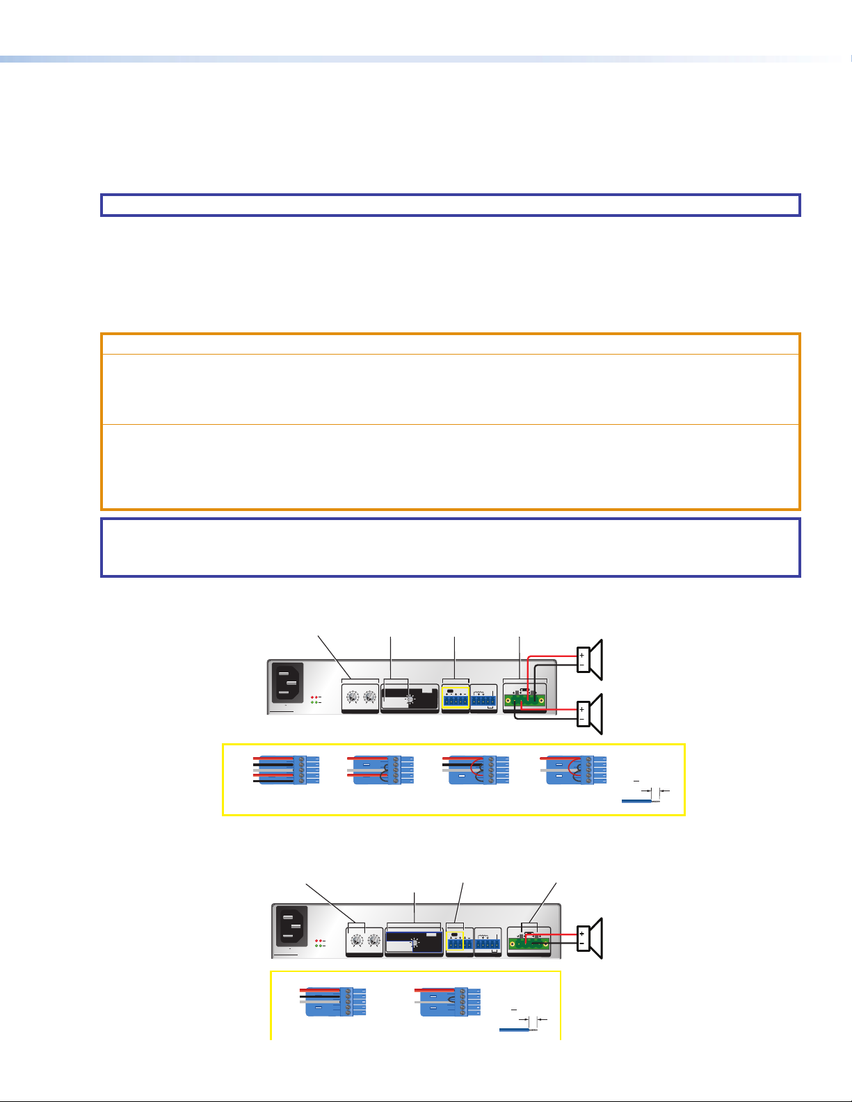
Stereo 8Ω or 4Ω Output Modes
Bridged Mono 8Ω/16Ω/70V/100V Modes
or 100V Speaker Loads
XPA U 1004 SB and XPA U 2002 SB • Setup Guide (Continued)
Set Amplifier Output Mode
Step 2 — Rear Panel Configuration
Follow the instructions below to learn how to configure the rear panel for both the XPA U 2002 SB and XPA U 1004 SB. Both units are
configured in the same way.
• Wire the source output to the Line Input 3.5mm captive screw port as shown below. Figure 3 shows both balanced and
unbalanced inputs.
NOTE: In bridged mono output modes, only the odd-numbered input connector is used.
• Set the output mode for a selected channel pair by adjusting the 8-position rotary switch. There are two Stereo modes and six
Bridged Mono modes.
• For stereo modes, connect a four 4-pin, 5 mm captive screw connector for two channels of speaker outputs. Each port has a
screw ange to secure the plug to the connector.
• For mono modes, connect the same 4-pin, 5 mm captive screw connector but wire only the middle speaker output pins for a
single channel of speaker output. See Figure 3 to learn how to wire the speaker output.
ATTENTION:
• Do not tie channel output pins to each other or to ground. Doing so will short out the outputs, damage the amplifier, or
both.
• Ne pas lier les sorties 1 et 2 des canaux entre elles ou à la terre. Les sorties pourraient être court-circuitées et/ou
l’amplificateur pourrait être endommagé.
• To avoid risk of damage to the amplifier or the speakers, always connect low-impedance speaker loads (8Ω/4Ω) and
high-impedance speaker loads (70V) to the appropriately marked output connectors on the amplifier.
• Pour éviter tout risque de détérioration de l’amplificateur ou des enceintes, connectez toujours les charges de l’enceinte
faible impédance (8Ω/4Ω) et les charges de l’enceinte haute impédance (70V) aux connecteurs de sortie correctement
identifiés sur l’amplificateur.
NOTE:
• You must use Class 2 wiring for this output to comply with UL requirements.
• XPA U 2002 SB is shown. Channels 3 and 4 of the XPA U 1004 SB are congured in the same way.
Use both CH 1 and CH 2
Attenuators (set
levels independently)
--A, 50-60 Hz
100-240V
XPA U 2002 SB
Tip
Ring
Sleeves
Tip
Ring
Stereo
Balanced Input
Use CH 1 Attenuator to
set level for bridged
output (CH 2 is ignored)
--A, 50-60 Hz
100-240V
XPA U 2002 SB
Set Output Mode to
appropriate stereo
setting (8Ω or 4Ω)
10
10
12
8
12
8
BRIDGED
6
14
6
14
1
2
LIMITER/
PROTECT
SIGNAL
Tip
Sleeves
Tip
Set Output Mode to appropriate
bridged mono setting (8Ω,16Ω,
70V, 100V). Use HPF OFF only
if HPF present in upstream DSP.
1
2
LIMITER/
PROTECT
SIGNAL
MONO
18
4
4
2
26
2
0
0
∞
∞
STEREO
21
ATTENUATION OUTPUT MODE
Stereo
Unbalanced Input
10
10
12
8
12
8
6
14
6
14
18
4
4
2
26
2
0
0
∞
∞
21
ATTENUATIONOUTPUT MODE
Wire CH 1 and CH 2
input connector based
on source as shown below
1
&2
16Ω
8Ω
70V
8Ω
70V (HPF OFF)
100V
4Ω
100V (HPF OFF)
Tip
Ring
Sleeves
1
8Ω
8Ω
4Ω
16Ω
70V
70V (HPF OFF)
100V
100V (HPF OFF)
&2
BRIDGED
MONO
STEREO
STANDBY
1&2
BR
(
)
1
2
G
GCV
INPUTS
REMOTE OUTPUTS
Dual Mono
Balanced Input
Wire CH 1 input
connector based on
source as shown below
STANDBY
1&2
BR
(
)
1
2
G
GCV
INPUTS
REMOTE OUTPUTS
Wire output connector
to speaker loads as
shown to the right
CLASS 2 WIRING
BR
1
2
Tip
Sleeves
Dual Mono
Unbalanced Input
Wire output connector
to mono speaker load
as shown to the right
CLASS 2 WIRING
BR
1
2
Do not tin
the wires!
3
"
(5 mm) MAX.
16
Sleeves
Ring
Tip
Mono
Balanced Input
Tip
Sleeves
Mono
Unbalanced Input
Figure 3. XPA SB Configuration Based on Output Mode
Stereo 8Ω or 4Ω
Speaker Loads
CH 2
CH 1
Do not tin
the wires!
3
"
(5 mm) MAX.
16
Mono 8Ω, 16Ω, 70V,
CH 1
3
Page 4

XPA U 1004 SB and XPA U 2002 SB • Setup Guide (Continued)
Step 3 — Remote Ports
XPA U 2002 SB XPA U 1004 SB
1 & 2
V
REMOTE
STANDBY
G
GC
3 & 4
1 & 2
GV C
G
STANDBY
GV C
REMOTE
Figure 4. Remote Volume Control and Standby Ports
The 3.5 mm 5-pin captive screw remote control port (shown above) is used to control volume on channels 1 & 2 on pins 1, 2, and 3,
and standby mode through contact closure on the pins 4 and 5. The XPA U 1004 SB has a an additional 3-pole captive screw port
directly above this port to control the volume on channels 3 & 4.
The volume control ports can be wired to Extron remote volume controllers such as an Extron VC 50, VCM 110 AAP, VCM 200 series,
MLA VC10 Plus, and select MLC controllers. For more details on wiring the volume control ports see the XPA U 1004 SB and XPA U
2002 SB User Guide.
When the STANDBY pin (pin 5) is shorted to ground (Pin 4), the amplifier goes into standby mode. Standby mode turns off all the
outputs, although the amplifier still receives power. The power LED on the front panel lights amber when the amplifier is in Standby
mode.
NOTE: A 10k ohm resistor is included with the amplifier. If the resistor is connected between the STANDBY and Ground
pin, the auto-standby timer is suppressed. The STANDBY pin can still be shorted to the Ground pin to put the amplifier in
standby.
Step 4 — Powering on Equipment
ATTENTION:
• The amplifier must be powered on last.
• L’amplificateur doit être mis sous tension en dernier.
Reconnect all the power cables and switch on all of the other equipment before attaching the IEC power cable and powering on the
unit. The power LED will light green.
Step 5 — Adjusting Attenuation
NOTE: Set the volume control on the connected control device(s) to maximum and ensure that the amplifier
is not currently forced into standby mode via the standby pin prior to making adjustments.
NOTE: When a channel pair is in bridged mono mode, only the odd channel’s attenuator knob is used.
Adjust audio attenuation using the rear panel adjustment attenuators as seen to the right.
See Rear Panel Features in the XPA U 1004 SB and XPA U 2002 SB User Guide for more information.
Step 6 — Checking LEDs
Check the Limiter/Protect and Signal LEDs on the front and rear panels to see if any problems are encountered (see Front Panel
Features and Troubleshooting in the XPA U 1004 SB and XPA U 2002 SB User Guide for more information)
10
12
8
6
14
18
4
26
2
0
∞
10
12
8
6
14
18
4
26
2
0
∞
1
ATTENUATION
10
8
12
6
14
4
2
0
∞
43
10
12
8
6
14
4
2
0
∞
2
For information on safety guidelines, regulatory compliances, EMI/EMF compatibility, accessibility, and related topics, see the
Extron Safety and Regulatory Compliance Guide on the Extron website.
© 2020 Extron Electronics — All rights reserved. www.extron.com
All trademarks mentioned are the property of their respective owners.
Worldwide Headquarters: Extron USA West, 1025 E. Ball Road, Anaheim, CA 92805, 800.633.9876
68-1351-50 Rev. A
07 20
 Loading...