

Page 1
XMP240CAT
Expansion Matrix Processor
User Guide
Audio Products
Mixers and Processors
68-3434-01 Rev. A
06 20
Page 2

Safety Instructions
Safety Instructions • English
WARNING: This symbol, , when used on the product, is intended
to alert the user of the presence of uninsulated dangerous voltage within
the product’s enclosure that may present a risk of electric shock.
ATTENTION: This symbol, , when used on the product, is intended
to alert the user of important operating and maintenance (servicing)
instructions in the literature provided with the equipment.
For information on safety guidelines, regulatory compliances, EMI/EMF
compatibility, accessibility, and related topics, see the Extron Safety and
Regulatory Compliance Guide, part number 68-290-01, on the Extron
website, www.extron.com.
Sicherheitsanweisungen • Deutsch
WARNUNG: Dieses Symbol auf dem Produkt soll den Benutzer darauf
aufmerksam machen, dass im Inneren des Gehäuses dieses Produktes
gefährliche Spannungen herrschen, die nicht isoliert sind und die einen
elektrischen Schlag verursachen können.
VORSICHT: Dieses Symbol auf dem Produkt soll dem Benutzer in
der im Lieferumfang enthaltenen Dokumentation besonders wichtige
Hinweise zur Bedienung und Wartung (Instandhaltung) geben.
Weitere Informationen über die Sicherheitsrichtlinien, Produkthandhabung,
EMI/EMF-Kompatibilität, Zugänglichkeit und verwandte Themen finden Sie in
den Extron-Richtlinien für Sicherheit und Handhabung (Artikelnummer
68-290-01) auf der Extron-Website, www.extron.com.
Istruzioni di sicurezza • Italiano
AVVERTENZA: Il simbolo, , se usato sul prodotto, serve ad
avvertire l’utente della presenza di tensione non isolata pericolosa
all’interno del contenitore del prodotto che può costituire un rischio di
scosse elettriche.
ATTENTZIONE: Il simbolo, , se usato sul prodotto, serve ad avvertire
l’utente della presenza di importanti istruzioni di funzionamento e
manutenzione nella documentazione fornita con l’apparecchio.
Per informazioni su parametri di sicurezza, conformità alle normative,
compatibilità EMI/EMF, accessibilità e argomenti simili, fare riferimento
alla Guida alla conformità normativa e di sicurezza di Extron, cod. articolo
68-290-01, sul sito web di Extron, www.extron.com.
I
Instrucciones de seguridad • Español
ADVERTENCIA: Este símbolo, , cuando se utiliza en el producto,
avisa al usuario de la presencia de voltaje peligroso sin aislar dentro del
producto, lo que puede representar un riesgo de descarga eléctrica.
ATENCIÓN: Este símbolo, , cuando se utiliza en el producto, avisa
al usuario de la presencia de importantes instrucciones de uso y
mantenimiento recogidas en la documentación proporcionada con el
equipo.
Para obtener información sobre directrices de seguridad, cumplimiento
de normativas, compatibilidad electromagnética, accesibilidad y temas
relacionados, consulte la Guía de cumplimiento de normativas y seguridad
de Extron, referencia 68-290-01, en el sitio Web de Extron, www.extron.com.
Instructions de sécurité • Français
AVERTISSEMENT : Ce pictogramme, , lorsqu’il est utilisé sur le
produit, signale à l’utilisateur la présence à l’intérieur du boîtier du
produit d’une tension électrique dangereuse susceptible de provoquer
un choc électrique.
ATTENTION : Ce pictogramme, , lorsqu’il est utilisé sur le produit,
signale à l’utilisateur des instructions d’utilisation ou de maintenance
importantes qui se trouvent dans la documentation fournie avec le
matériel.
Pour en savoir plus sur les règles de sécurité, la conformité à la
réglementation, la compatibilité EMI/EMF, l’accessibilité, et autres sujets
connexes, lisez les informations de sécurité et de conformité Extron, réf.
68-290-01, sur le site Extron, www.extron.com.
Page 3
Copyright
© 2020 Extron Electronics. All rights reserved. www.extron.com
Trademarks
All trademarks mentioned in this guide are the properties of their respective owners.
The following registered trademarks (®), registered service marks (SM), and trademarks (TM) are the property of RGBSystems, Inc. or
ExtronElectronics (see the current list of trademarks on the Terms of Use page at www.extron.com):
Registered Trademarks (
®
)
Extron, Cable Cubby, ControlScript, CrossPoint, DTP, eBUS, EDID Manager, EDID Minder, Flat Field, FlexOS, Glitch Free. Global
Configurator, GlobalScripter, GlobalViewer, Hideaway, HyperLane, IPIntercom, IPLink, KeyMinder, LinkLicense, LockIt, MediaLink,
MediaPort, NAV, NetPA, PlenumVault, PoleVault, PowerCage, PURE3, Quantum, ShareLink, Show Me, SoundField, SpeedMount,
SpeedSwitch, StudioStation, SystemINTEGRATOR, TeamWork, TouchLink, V-Lock, VideoLounge, VN-Matrix, VoiceLift, WallVault, WindoWall,
XPA, XTP, XTPSystems, and ZipClip
Registered Service Mark
(SM)
: S3 Service Support Solutions
Trademarks (™
)
AAP, AFL (Accu-RATEFrameLock), ADSP(Advanced Digital Sync Processing), Auto-Image, AVEdge, CableCover, CDRS(ClassD
Ripple Suppression), Codec Connect, DDSP(Digital Display Sync Processing), DMI (DynamicMotionInterpolation), DriverConfigurator,
DSPConfigurator, DSVP(Digital Sync Validation Processing), eLink, EQIP, Everlast, FastBite, Flex55, FOX, FOXBOX, IP Intercom
HelpDesk, MAAP, MicroDigital, Opti-Torque, PendantConnect, ProDSP, QS-FPC(QuickSwitch Front Panel Controller), RoomAgent,
Scope-Trigger, SIS, SimpleInstructionSet, Skew-Free, SpeedNav, Triple-Action Switching, True4K, True8K, Vector™ 4K, WebShare, XTRA,
and ZipCaddy
Page 4
FCC Class A Notice
This equipment has been tested and found to comply with the limits for a Class A digital
device, pursuant to part15 of the FCC rules. The ClassA limits provide reasonable
protection against harmful interference when the equipment is operated in a commercial
environment. This equipment generates, uses, and can radiate radio frequency energy and,
if not installed and used in accordance with the instruction manual, may cause harmful
interference to radio communications. Operation of this equipment in a residential area is
likely to cause interference. This interference must be corrected at the expense of the user.
ATTENTION:
• The Twisted Pair Extension technology works with unshielded twisted pair (UTP)
• La technologie extension paires torsadées fonctionne avec les câbles paires
NOTES:
• This unit was tested with shielded I/O cables on the peripheral devices. Shielded
• For more information on safety guidelines, regulatory compliances, EMI/EMF
or shielded twisted pair (STP) cables; but to ensure FCC Class A and CE
compliance, STP cables and STP Connectors are required.
torsadées blindées(UTP) ou non blindées(STP). Afin de s’assurer de la
compatibilité entre FCC ClasseA et CE, les câbles STP et les connecteurs STP
sont nécessaires.
cables must be used to ensure compliance with FCC emissions limits.
compatibility, accessibility, and related topics, see the Extron Safety and
Regulatory Compliance Guide on the Extron website.
Battery Notice
This product contains a battery. Do not open the unit to replace the battery. If the
battery needs replacing, return the entire unit to Extron (for the correct address, see the
Extron Warranty section on the last page of this guide).
CAUTION: Risk of explosion. Do not replace the battery with an incorrect type.
Dispose of used batteries according to the instructions.
ATTENTION : Risque d’explosion. Ne pas remplacer la pile par le mauvais type de
pile. Débarrassez-vous des piles usagées selon le mode d’emploi.
Page 5

Conventions Used in this Guide
Notifications
The following notifications are used in this guide:
CAUTION: Risk of minor personal injury.
ATTENTION : Risque de blessuremineure.
ATTENTION:
• Risk of property damage.
• Risque de dommages matériels.
NOTE: A note draws attention to important information.
TIP: A tip provides a suggestion to make working with the application easier.
Software Commands
Commands are written in the fonts shown here:
^AR Merge Scene,,0p1 scene 1,1 ^B 51 ^W^C.0
[01] R 0004 00300 00400 00800 00600 [02] 35 [17] [03]
E X! *X1&* X4!* X5@* X2! CE}
NOTE: For commands and examples of computer or device responses used in
this guide, the character “0” is used for the number zero and “O” is the capital
letter “o.”
Computer responses and directory paths that do not have variables are written in the font
shown here:
Reply from 208.132.180.48: bytes=32 times=2ms TTL=32
C:\Program Files\Extron
Variables are written in slanted form as shown here:
ping xxx.xxx.xxx.xxx —t
SOH R Data STX Command ETB ETX
Selectable items, such as menu names, menu options, buttons, tabs, and field names are
written in the font shown here:
From the File menu, select New.
Click the OK button.
Specifications Availability
Product specifications are available on the Extron website, www.extron.com.
Extron Glossary of Terms
A glossary of terms is available at http://www.extron.com/technology/glossary.
aspx.
XMP 240 C AT • Introduction iii
Page 6

Contents
Introduction ................................................1
About this Guide .................................................. 1
About the XMP240CAT .................................... 1
Features .............................................................. 1
Application Diagram ............................................ 3
Installation .................................................. 4
Mounting ............................................................. 4
Rear Panel Features and Cabling ......................... 5
Front Panel Features ............................................ 8
Hardware Reset Modes ....................................... 9
Mode 1 — Firmware Reset .............................. 9
Mode 4 — IP Reset ......................................... 9
Mode 5 — Factory Default Reset ..................... 9
DSP Configurator Software .......................10
Downloading and Installing DSP Configurator .... 10
Accessing the DSP Configurator Help File ......... 11
DSP Configurator Main Workspace ................... 11
Menu Bar .......................................................... 12
File ................................................................ 12
Edit ................................................................ 13
View .............................................................. 13
Tools .............................................................. 14
Window ......................................................... 15
Help .............................................................. 15
Macros Drop-Down ....................................... 16
Presets Drop-Down ....................................... 16
DSP Configurator Status Panel ...................... 16
Live and Emulate Panel.................................. 17
DSP Configurator Inputs .................................... 20
Inputs ................................................................ 20
Renaming an Input ........................................ 20
Inputs Overview ............................................. 21
Input Building Blocks ..................................... 22
Input Processing ................................................ 23
Input Gain Block ............................................ 24
Input Filter Block ............................................ 25
Input AEC Block ............................................ 27
Input Dynamics Blocks .................................. 30
Input Delay Block ........................................... 35
Input Ducking Block ...................................... 36
Input Automix Block ...................................... 39
Input Pre-Mixer Gain Block ............................ 40
Virtual Returns ................................................... 41
Renaming a Virtual Return ............................. 42
Virtual Return Building Blocks ........................ 42
Virtual Return Processing .................................. 42
Virtual Return Feedback Suppressor Block .... 43
Virtual Return Filter Block ............................... 47
Virtual Return Dynamics Block ....................... 47
Virtual Return Delay Block ............................. 47
Virtual Return Pre-Mixer Gain Block ............... 47
Mix-Points ......................................................... 47
Mix-Point Dialog Box ..................................... 49
Mix-Point Context Menu ................................ 50
DSP Configurator Outputs ................................. 50
Outputs ............................................................. 51
Naming an Output ......................................... 51
Output Building Blocks .................................. 51
Output Processing ............................................. 53
Output Trim Block .......................................... 53
Output Delay Block ........................................ 54
Output Filter Block ......................................... 54
Output Dynamics Block ................................. 54
Output Attenuation Block............................... 54
Virtual Send Bus ................................................ 55
ivXMP 240 C AT • Contents
Page 7

Configuration Tools ................................... 67
Presets .............................................................. 67
Methods for Marking Items ............................ 68
Configuring Presets ....................................... 68
Groups .............................................................. 69
Configuring Groups ....................................... 70
Macros .............................................................. 72
Configuring a Macro ...................................... 73
Device Manager ................................................ 76
Managing Devices in Device Manager ............ 77
Connect to or Disconnect from Device .............. 78
Firmware Loader ............................................... 79
Downloading Firmware Updates .................... 79
Organize Building Blocks ................................... 82
Device Settings.................................................. 83
Unit Info ......................................................... 83
IP Settings .................................................... 84
Passwords .................................................... 84
Serial Settings ............................................... 85
Date/Time .................................................... 85
Dante Device ................................................ 86
Options ............................................................. 87
Expansion Bus .................................................. 88
Connecting the EXP Ports ............................. 88
Dante Controller ........................................89
Overview ........................................................... 89
Downloading and Installing Dante Controller ...... 90
Configuring the XMP240CAT in
Dante Controller ............................................... 90
Device Name ................................................. 90
Receiver and Transmitter Names ................... 91
Dante Controller Naming Conventions ........... 91
Renaming the XMP240CAT in
Dante Controller ........................................... 91
Renaming a Receiver or Transmitter............... 93
Finding a Dante Device IP Address ................ 95
Physical Dante Network Setup .......................... 96
Redundant Configuration ............................... 96
Dante Controller Operation ................................ 98
Dante Transmitters and Receivers .................. 98
Dante Routing Operation ............................... 98
Routing Devices............................................. 98
Disconnecting Inputs from Outputs .............. 100
Sending SIS Commands to Dante Audio
Interface Devices through the XMP ............. 100
Dante Troubleshooting ..................................... 101
Simplifying the Network for
Troubleshooting .......................................... 101
Troubleshooting the Network Interface ......... 101
Restarting Dante Controller .......................... 102
Remote Communication and Control .......103
Connection Options ......................................... 103
RS-232 Port ................................................ 104
LAN Port ..................................................... 104
USB Config Port .......................................... 105
Verbose Modes ........................................... 105
Host-to-Device Communications ..................... 106
XMP240CAT-initiated Messages ............... 106
SIS Overview ................................................... 107
Using the Command and Response
Tables ......................................................... 107
Symbol Definitions ....................................... 107
Error Responses .............................................. 108
Simple Control Port Commands ...................... 108
Command and Response Table Sections ........ 109
Command and Response Table for
Basic SIS Commands ................................. 109
DSP SIS Commands ................................... 123
Symbol Definitions ....................................... 123
Special Characters ...................................... 123
Command and Response Table for
DSP SIS Commands .................................. 124
Object ID (OID) Number Tables ........................ 129
Input Path OIDs ........................................... 129
Output Attenuation Block OIDs .................... 131
Output Path OIDs ........................................ 132
Mix-point OIDs............................................. 133
Web Pages .............................................. 142
XMP240CAT Web Page .............................. 142
Accessing the Embedded Web Page ........... 142
Using the Web Page .................................... 143
XMP 240 C AT • Contents v
Page 8

Introduction
This section describes this user guide and the XMP240CAT. The following topics are
covered:
• About this Guide
• About the XMP240CAT
• Features
• Application Diagram
About this Guide
This guide contains installation, configuration, and operating information for the Extron
XMP240CAT Expansion Matrix Processor. In this guide, the XMP240CAT may also be
referred to as “XMP” or “device”.
About the XMP240CAT
Features
The XMP 240 Expansion Matrix Processor features an extensive mix matrix with 24
channels of AEC and 48x48 Dante® connectivity in only a half rack space. The XMP
240 can also be used standalone for matrix processing in an all network audio system.
When connected to a DMP Plus Series processor via Dante or the EXP expansion port, a
complete system is created that features up to 36 channels of AEC, a USB audio interface,
analog connectivity, and optional VoIP. A system expanded with an XMP 240 is capable
of supporting multiple beam forming microphone arrays alongside numerous other Dante
sources, with enough outputs to support multiple zones and destination devices. Ideal for
network audio systems based on Dante or AES67, the XMP 240 allows for high channel
count audio input and output processing.
• 24 channels of AEC - acoustic echo cancellation — The XMP 240 includes
24 independent channels of high performance AEC, as well as selectable noise
cancellation. Extron AEC features advanced algorithms that deliver fast echo canceler
convergence for optimal intelligibility in situations that challenge AEC performance.
• Dante audio networking with Dante Domain Manager and AES67 support —
Dante audio networking provides scalability for creating larger audio matrixes over a
local area network using standard protocols. A built-in two-port Gigabit switch can be
configured to support primary and redundant Dante audio networks.
• Extensive mix matrix with input and output processing — Allows all inputs to be
discretely routed to any or all outputs, with processing.
• FlexInput capability on all inputs for input source selection — All 48 inputs
offer FlexInput capability to select a Dante channel or expansion input. This allows
incorporating the full range of DSP capabilities, including AEC, for any incoming signal.
XMP 240 C AT • Introduction 1
Page 9

• Macros allow the sequencing of commands that can be sent to the local device
or external devices via the LAN port — A single XMP 240 can act as the central
interface from a control system, sending commands to other DMP Plus, AXI AT, and
DTP CrossPoint devices.
• Compact half rack size — Allows more input and output channels, with more
processing power, to be installed in less space.
• Advanced audio processing on all outputs — Up to 48 speaker zones can be
implemented on one XMP 240 with full processing for each zone, making it ideal for full
mix-minus implementations.
• Adaptive Gain Processing — An adaptive gain processor block allows a specified
microphone input to affect levels on any one or all other inputs and virtual returns.
• Built-in two-port Gigabit switch — Provides redundant or daisy-chain operation with
other Dante-enabled devices.
• Automixer with eight groups — The XMP 240 features an automixer with gated and
gain sharing modes for managing up to eight groups of microphone signals. Gating
threshold, signal level reduction, and timing parameters are user-adjustable per channel,
allowing for fine-tuning to avoid the “chopped” sound characteristic of a traditional
automixer when a mic is gated off.
• ProDSP 64-bit floating point signal processing — The XMP 240 features 64-bit
floating point audio DSP processing, which maintains very wide dynamic range and
audio signal transparency, to simplify management of gain staging while reducing the
possibility of DSP signal clipping.
• DSP Configurator™ Software — A powerful yet user-friendly PC-based software
tool for managing all audio operations of the XMP 240. It enables complete setup
and configuration of digital audio processing tools on the ProDSP platform, as well as
routing and mixing.
• Building Blocks for channel processor settings — A collection of pre-designed
processor settings optimized for a specific type of input and output devices, such as
microphones and speakers. Flexible Building Blocks are available on each input strip
and allow system designers to fully customize and save their own Building Blocks,
further streamlining audio system design and integration.
• Live and Emulate operation modes with configuration file saving — Live mode
allows integrators to connect to the XMP 240 and make live parameter adjustments
while hearing or metering them in real-time. This avoids the need to compile and upload
a configuration file to the DSP. Emulate mode allows settings to be configured offline,
then uploaded to the XMP 240. Additionally, current settings on a XMP 240 can be
backed up to a configuration file for archiving.
• Group masters — The XMP 240 provides the capability to consolidate gain or mute
control throughout the system. Gain or mute controls can be selected and added
to a group master, which can then be controlled by a single master fader or mute
control. Loudness filters can also be added to a group master, which enables the
loudness curve to track with the program volume control. Bass and Treble filters can
be configured in a group master to provide boost and cut as user controls. Additionally,
Meters can be added to a group, providing a control to enable and disable multiple
meters at once. Each group master can have up to 128 members, and up to 64 group
masters can be created.
XMP 240 C AT • Introduction 2
Page 10
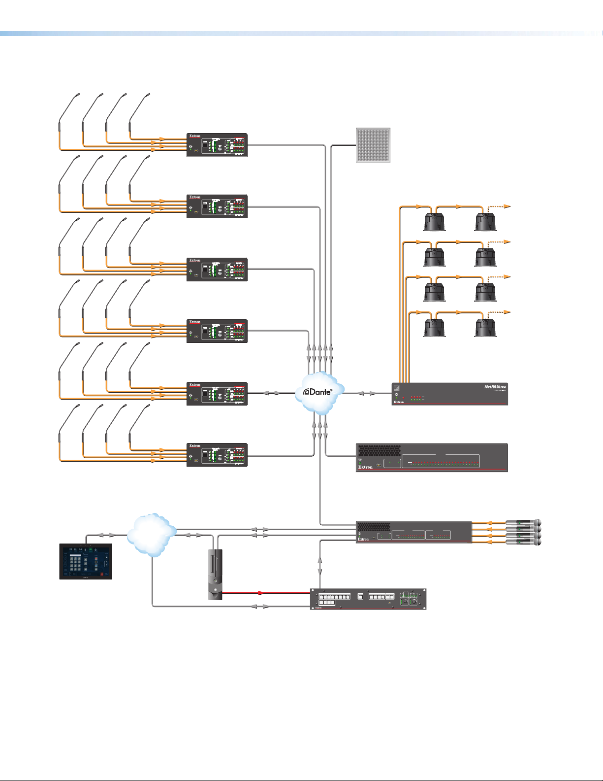
Application Diagram
DIGITAL PRESENTATION MATRIX
Multi-Purpose Room - Table Mics
Ethernet/PoE
Extron
TLP Pro 1025T
10" Tabletop
TouchLink Pro
Touchpanel
Tabl e M ics
CONFIG
AXI 44 AT
Extron
AXI 44 AT
Dante Audio Interface
Tabl e M ics
CONFIG
AXI 44 AT
Extron
AXI 44 AT
Dante Audio Interface
Tabl e M ics
CONFIG
AXI 44 AT
Extron
AXI 44 AT
Dante Audio Interface
Tabl e M ics
CONFIG
AXI 44 AT
Extron
AXI 44 AT
Dante Audio Interface
Tabl e M ics
CONFIG
AXI 44 AT
Ethernet
Extron
AXI 44 AT
Tabl e M ics
Dante Audio Interface
AXI 44 AT
CONFIG
Ethernet
Extron
AXI 44 AT
Dante Audio Interface
Ethernet
LAN/VoIP
Ethernet
USB Audio
EXP
PC (with
USB Audio
HDMI
and Zoom)
Ethernet
Figure 1. XMP240CAT Application Diagram
2
1
2
1
INPUTS
4
3
4
3
OUTPUTS
Ceiling
Array Mic
6 Speakers per Ch./Zone
Tapped @ 16W
6x16W = 96 watts per ch.
Extron
Ethernet
SF 26CT
Two-Way Ceiling Speakers
OVER
TEMP
2
1 3 4
LIMITER/PROTECT
Ethernet
SIGNAL
Extron
NetPA U 1004-70V
Power Amplier
ACTIVITY
1 2 3 4 5 6 7 8 9 10 11 12 13 14 15 16 17 18 19 20 21 22 23 24
CLIP
EXP LAN
CONFIG
SIGNAL
Extron
XMP 240 C AT
Expansion Matrix Processor
ACTIVITY
1 2 3 4 5 6 7 8 1 2 3 4 5 6 7 89 10 1112
CLIP
EXP
LAN 1
CONFIG
SIGNAL
USB
LAN 2
Extron
DMP 128 FlexPlus C V AT
Dante Digital Matrix Processor
CONTROL I/O
LOGO
SELECT
7
6
5
8
AUDIO
ESC
ENTER PRESET
VIDEO
VIEW
CONFIG
COM
RTS
eBUS
CTS
S LIMIT
Tx
Rx
OVER
1 2 23 3 4
MIC VOLUME VOLUME
DTP CROSSPOINT 4K SERIES
CLIP
SIGNAL
IR/S I/O
RELAYS
1 1 2
1 2
3 4
NetPA U 1004 SERIES
INPUTS
XMP 240 C AT
EXPANSION MATRIX PROCESSOR
Audio
OUTPUTSINPUTS
DMP 128 FlexPlus
DIGITAL MATRIX PROCESSOR
mut
e
select mut
e
select mut
e
select mut
e
select
Wireless
Mics
Extron
DTP CP 84 4K IPCP SA
Presentation Matrix Switcher
XMP 240 C AT • Introduction 3
Page 11

Installation
This section describes the installation of the XMP240CAT and covers the following topics:
• Mounting
• Rear Panel Features and Cabling
• Front Panel Features
• Hardware Reset Modes
Mounting
The 1U high, half rack width, 9.5 inch deep XMP240CAT mounts in the following manners:
• Rack mounting — Attach the XMP240CAT to a standard 19-inch rack shelf. The
following Underwriters Laboratories (UL) guidelines pertain to the installation of the
XMP240CAT in a rack:
• Reduced air flow — Install the equipment in the rack so that the amount of air
flow required for safe operation of the equipment is not compromised.
• Mechanical loading — Mount the equipment in the racks so that uneven
mechanical loading does not create a hazardous condition.
• Circuit overloading — When connecting the equipment to the supply circuit,
consider the effect that circuit overloading might have on overcurrent protection
and supply wiring. Consider equipment nameplate ratings when addressing this
concern.
• Reliable earthing (grounding) — Maintain reliable grounding of rack-mounted
equipment. Pay particular attention to power supply connections other than direct
connections to the branch circuit (such as the use of power strips).
• Under-furniture mounting — Mount the XMP240CAT under the surface of a desk,
table, or podium.
• Free-standing — Attach the four rubber feet provided with the device to the bottom of
the XMP240CAT in the four corners and place the unit on furniture as desired.
NOTE: To mount the XMP240CAT using an Extron mounting kit, see the instructions
provided with the kit.
XMP 240 C AT • Installation 4
Page 12
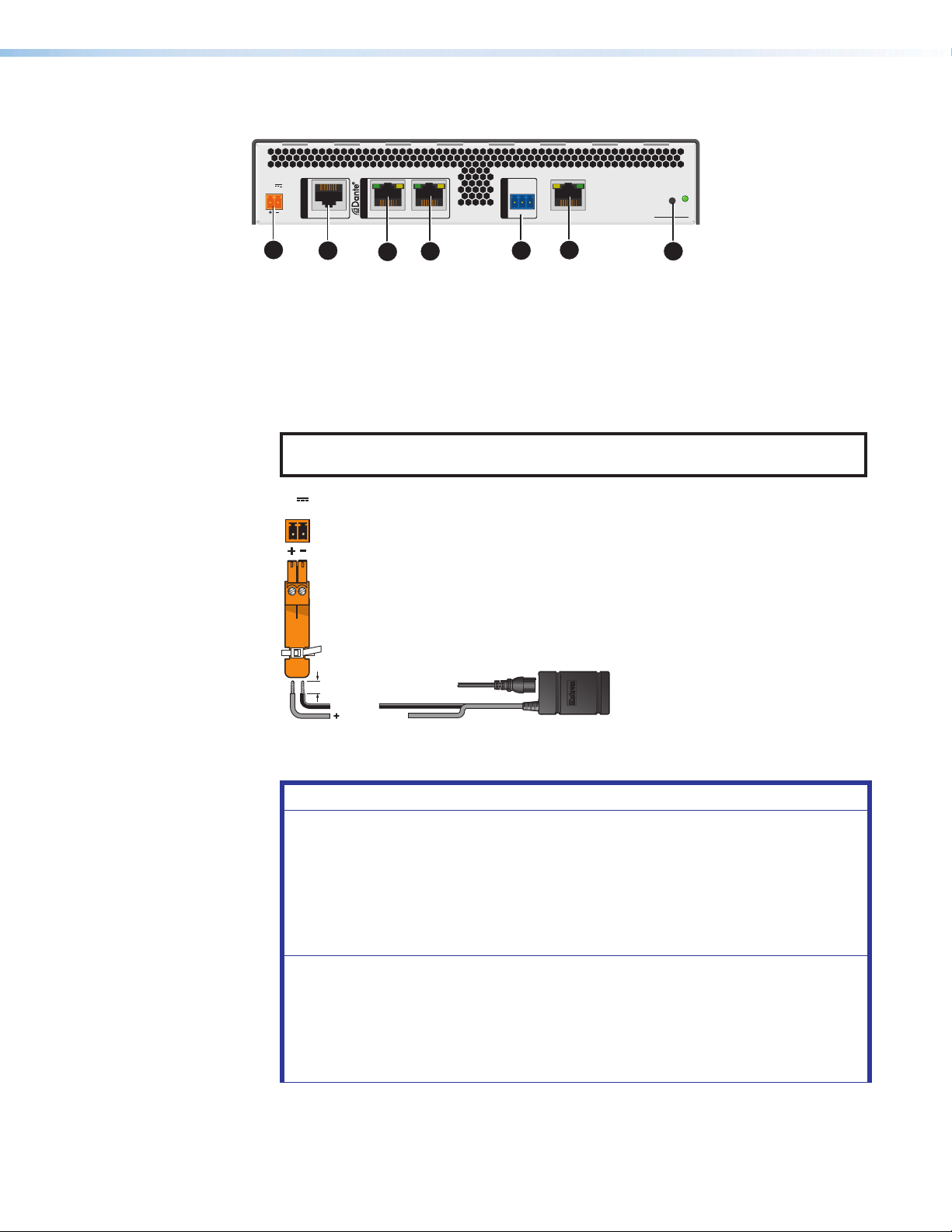
Rear Panel Features and Cabling
y
(12 VDC, 2.0 A max.)
POWER
12
2.0A MAX
POWER
12V
1.0A MAX
DMP EXP
AT
1 (PRI) PoE 2 (SEC)
RS-232
REMOTE
Tx Rx G
LAN
R
XMP 240 C AT
A
Power Input
A
EXP Port
B
AT Ports
C
B
C
C
D
E
RS-232 Port
D
LAN Port
E
Reset Button and LED
F
F
Figure 2. XMP240CAT Rear Panel
Power Input — Connect the included external 2-pole captive screw power supply (see
A
the figure below for power supply wiring information).
NOTE: If a power supply is not provided, use a UL Listed power supply with rated
output 12 VDC, minimum 1.5 A, and marked “Class 2” or “LPS”.
V
Rear Panel
Power Receptacle
DC Power Cord
Captive Screw
Connector
3/16"
(5 mm) Max.
Ground
G
+12 VDC input
Ground all
Devices
External Power Suppl
Figure 3. Power Input Wiring
ATTENTION:
• Always use a power supply provided by or specied by Extron. Use of an
unauthorized power supply voids all regulatory compliance certication
and may cause damage to the supply and the end product.
• Utilisez toujours une source d’alimentation fournie ou recommandée par
Extron. L’utilisation d’une source d’alimentation non autorisée annule toute
certication de conformité réglementaire, et peut endommager la source
d’alimentation et l’unité.
• The installation must always be in accordance with the applicable
provisions of National Electrical Code ANSI/NFPA 70, article 725 and the
Canadian Electrical Code part 1, section 16.
• L’installation doit toujours être conforme aux dispositions applicables du
Code américain de l’électricité (National Electrical Code) ANSI/NFPA 70,
article 725, et du Code canadien de l’électricité.
XMP 240 C AT • Installation 5
Page 13

• These products are intended for use with a UL Listed power source
Connected RS-232
marked “Class 2” or “LPS” and rated 12 VDC, minimum 1.0 A. or 48 VDC
(PoE), minimum 0.35 A, or 56 VDC (PoE), minimum 0.8 A.
• Ces produits doivent être utilisés avec une source d’alimentation certiée
UL de classe 2 ou LPS avec une tension nominale 12 Vcc, 1,0 A minimum,
ou 48 Vcc (PoE), 0,35 A minimum, ou 56 Vcc (PoE), 0,8 A minimum.
• The power supply shall not be permanently xed to building structure or
similar structure.
• La source d’alimentation ne devra pas être xée de façon permanente à la
structure de bâtiment ou à d’autres structures similaires.
• Power over Ethernet (PoE) is intended for indoor use only. It is to be
connected only to networks or circuits that are not routed to the outside
plant or building.
• L’alimentation via Ethernet (PoE) est destinée à une utilisation en intérieur
uniquement. Elle doit être connectée seulement à des réseaux ou des
circuits qui ne sont pas routés au réseau ou au bâtiment extérieur.
• The XMP is intended for connection to a Power over Ethernet circuit
for intra-building use only and are considered to be part of a Network
Environment 0 per IEC TR62101.
• Le XMP est conçu pour une connexion à un circuit PoE pour une
utilisation intérieure seulement et est considéré comme faisant partie d’un
environnement réseau 0 par IECTR62101.
EXP Port — One RJ-45 port allows two units to be connected via a shielded CAT 6
B
cable to form a larger matrix system (1 foot cable included). Any Extron device with EXP
capability can exchange audio with a XMP240CAT via the EXP port.
AT Ports — Two RJ-45 ports form a Gigabit switch for use with a Dante network. The
C
AT ports use Dante protocol for digital audio transport (AT) and allow the XMP240CAT
to connect to a Dante audio network to form a larger matrix (Dante Controller on
page89). The 2-port switch can be configured as one primary and one secondary
port for redundant Dante configurations. In redundant configuration, audio traffic is
duplicated. Port 1 is the primary port (PRI) and Port 2 is the secondary switch (SEC)
(see Redundant Configuration on page96).
The AT port LEDs indicate the following:
• Green only = 100 Mbps connection
• Amber only = 1 Gb connection
RS-232 Port — Use a 3-pole 3.5 mm captive screw connector to connect the host
D
RS-232 cable for bidirectional RS-232 (±5V) serial control (see figure 5 for wiring). The
default baud rate is 38400.
Device Pins
Receive
Transmit
Ground
RS-232
REMOTE
Tx Rx G
Figure 4. RS-232 Wiring Example
XMP 240 C AT • Installation 6
Page 14

LAN Port — One RJ-45 port provides a Gigabit network connection for control. The
E
host PC or control system and the XMP240CAT must be connected to the same
network. Two LEDs indicate status.
LAN defaults:
IP Address Subnet Mask Default Gateway DHCP
192.168.254.254 255.255.255.0 0.0.0.0 OFF
Reset Button and LED —The reset button returns the XMP240CAT to different tiers
F
of default states. When using the reset button, the LED blinks to signify the different
reset modes (Hardware Reset Modes on page8). When not displaying reset
modes, the LED operates as a power indicator, matching the front panel power LED.
Front Panel Features
CONFIG
B C DA
ACTIVITY
EXP LAN
INPUTS
1 2 3 4 5 6 7 8 9 10 11 12 13 14 15 16 17 18 19 20 21 22 23 24
CLIP
SIGNAL
XMP 240 C AT
EXPANSION MATRIX PROCESSOR
Power LED
A
USB Config Port
B
Activity Indicator LEDs
C
Input Indicator LEDs
D
Figure 5. XMP240CAT Front Panel
Power LED — Blinks during boot up and lights steadily when the XMP240CAT is
A
operational.
USB Config Port — One USB mini-B port is used for configuration. This port can also
B
be used for firmware updates.
Activity Indicator LEDs — These green activity LEDs indicate port activity on the
C
XMP240CAT:
• EXP Indicator LED —
• On — The unit is connected to a second EXP device and is configured as the
primary unit.
• Blinking — The unit is not connected to a second device.
• LAN Activity Indicator LED — Blinks to indicate rear panel LAN port activity.
Input Indicator LEDs — 24 stacked pairs of green and red LEDs display input signal
D
presence and input signal clipping.
The green signal presence LED varies in brightness, corresponding to the real-time
input signal level. It lights at -60 dBFS and increases in brightness until signal level
reaches -3 dBFS. When the signal reaches or exceeds -3 dBFS, the red clip LED lights.
The clip LED remains lit for 200 ms after the signal last clipped.
XMP 240 C AT • Installation 7
Page 15

Hardware Reset Modes
NOTE: The reset modes listed below close all IP connections, Telnet connections, and
sockets.
Mode 1 — Firmware Reset
Hold the Reset button (see figure 2 on page5) while applying power to restore the unit
firmware back to the default factory firmware. This recovers a unit that has incorrect code or
updated firmware running. All user files and settings are maintained.
Mode 4 — IP Reset
With power on, press and hold the Reset button until the reset LED blinks twice
(~6 seconds). Release the button and, within 1 second, press it again to reset all IP address
settings to factory default.
The following changes take place:
• ARP program capability is enabled
• Sets IP addresses for LAN port back to factory default (192.168.254.254)
• Sets subnet masks for LAN port back to factory default (255.255.255.0)
• Sets gateways for LAN port back to factory default
• Turns DHCP off for LAN port
If a second momentary press does not occur within 1 second, Mode 4 is exited.
Mode 5 — Factory Default Reset
With power on, press and hold the Reset button until the reset LED blinks 3 times
(~9 seconds). Release the button and, within 1 second, press it again to return the
XMP240CAT to factory default conditions.
The following changes take place:
• Sets all IP settings back to factory default (see Mode 4 above)
• Mix-points are set to unity gain (0 dB)
• All audio inputs are set to unity gain
• All outputs are unmuted and set to unity gain
• Any inserted or active DSP is removed
• All preset, group master, and macro memory is cleared
XMP 240 C AT • Installation 8
Page 16

DSP Configurator Software
The XMP240CAT has no front panel hardware controls. To configure and operate the XMP,
use a PC running Microsoft® Windows® 7 or newer and Extron DSPConfigurator software.
This section describes Extron DSP Configurator software and covers the following topics:
• Downloading and Installing DSP Configurator • Mix-Points
• Accessing the DSP Configurator Help File • DSP Configurator Outputs
• DSP Configurator Main Workspace • Outputs
• Menu Bar • Output Processing
• DSP Configurator Inputs • Expansion Outputs
• Input Processing • Expansion Output Processing
• Virtual Returns • Virtual Send Bus
• Virtual Return Processing
Downloading and Installing DSP Configurator
1. From www.extron.com, hover over the Download tab at the top of the page.
2. From the Featured Software list, select DSP Configurator Software.
3. From the DSP Configurator Software product page, click the blue Download button.
4. Select Run to run the DSP Configurator installer. Select Save to save the install file to run
at a later time.
5. To run DSP Configurator from the default install location, click
Start> Programs > Extron Electronics > DSP Configurator> DSP Configurator.
6. From the DSP Configurator splash screen drop-down menu (figure 10, 1), select the
model of XMP240CAT being connected to the host PC and click OK(2).
Figure 6. DSP Configurator Splash Screen
XMP 240 C AT • DSP Configurator Software 10
Page 17
Accessing the DSP Configurator Help File
DSP Configurator comes loaded with a context-sensitive help file that can be accessed by
clicking the help icon ( ) in the top right corner of any dialog box in DSP Configurator.
Alternatively, click Help > Contents in the menu bar at the top of the main workspace,
or press <F1> on your keyboard. This help file contains detailed procedures and further
instruction on all DSP Configurator features.
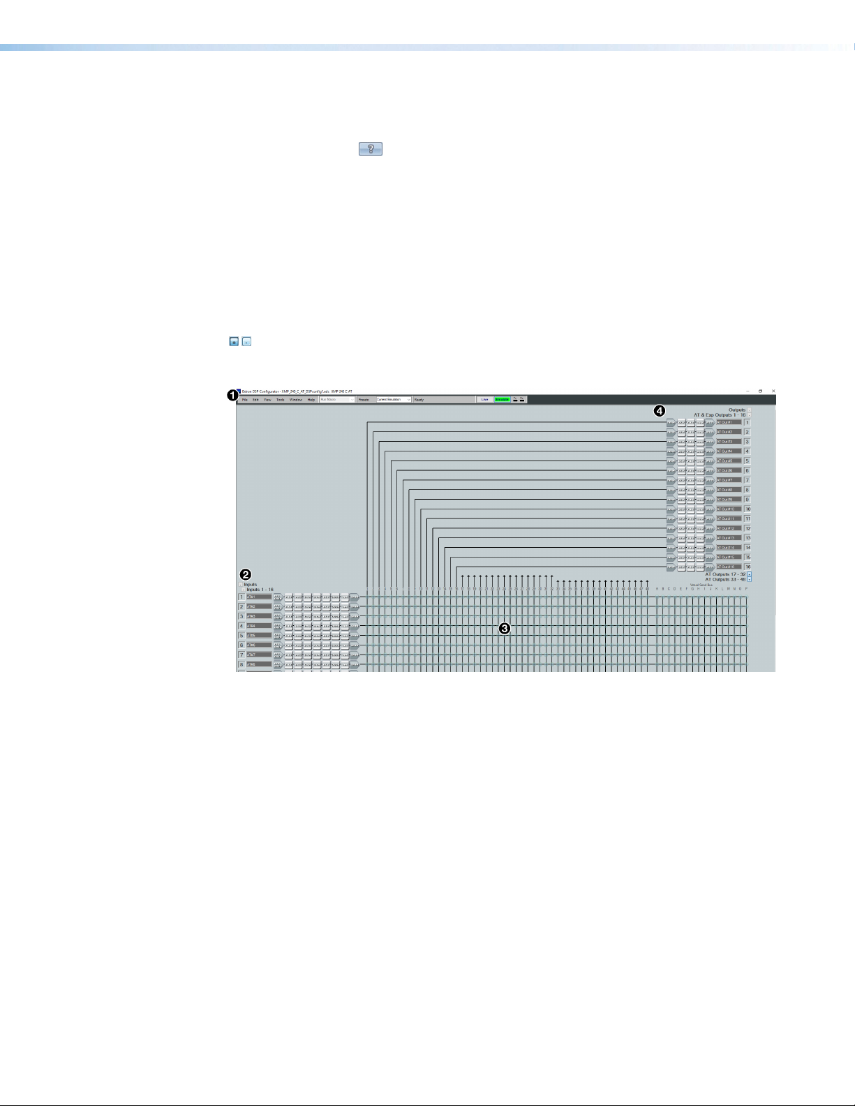
DSP Configurator Main Workspace
The DSP Configurator main workspace can be divided up into four main sections (see
figure 7). Each section contains various functions to configure the XMP240CAT. Due to the
large number of inputs and outputs available on the XMP240CAT, not all channels can be
viewed at the same time in a single window. Use the expand and collapse buttons
( ) next to the input and output group names to show or hide input and output groups
and their corresponding mix matrices. If necessary, scroll through the window by using the
mouse wheel or the scroll bar at the right side of the DSP Configurator main workspace.
Menu Bar on the next page
1
Inputs on page20
2
Figure 7. DSP Configurator Main Workspace
XMP 240 C AT • DSP Configurator Software 11
Mix-Points on page47
3
Outputs on page51
4
Page 18
Menu Bar
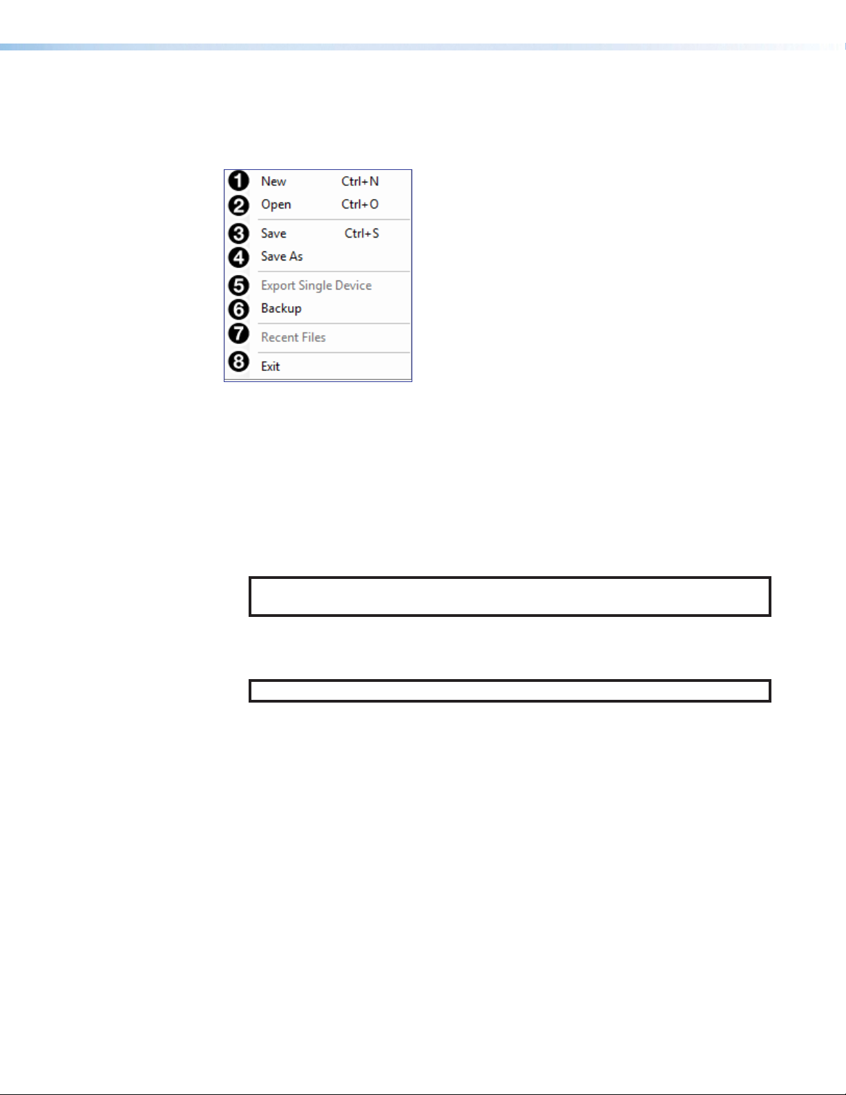
File
Figure 8. File Menu
New — Opens a new configuration file. This option is only available in Emulate mode
1
(Emulate Mode on page17). If the current configuration has not been saved,
the Save dialog box opens and asks to save the current configuration before a new
configuration is opened. Click Yes to save the current configuration. Click No to delete
the current configuration and open the new configuration. Click Cancel to return to the
current configuration.
Open — Opens an existing configuration or template file. When selected, the Browse
2
dialog box opens to search for saved configuration or template files. Double-click a
configuration or template file to load it.
NOTE: Configuration files have a .EDC file extension and template files have a .EDCT
file extension.
Save — Saves the current configuration to a configuration file. If this is the first time the
3
configuration is being saved, the Save Configuration As... dialog box opens. Enter a
name and save location for the configuration file.
TIP: It is best to create and save configuration files while in Emulate mode.
Save As — Saves the current configuration file under a new name and location or as a
4
template file. When selected, the Save Configuration As... dialog box opens.
Export Single Device — Saves the currently selected device in Device Manager as
5
a configuration file. This function is used to save an individual device when there are
multiple devices listed in the Device Manager (Device Manager on page76).
Backup — Recalls and transfers all partial presets of a XMP240CAT to the
6
configuration file or template file within DSP Configurator.
Recent Files — Lists the five most recently opened configuration files. These files can
7
be selected and loaded into DSP Configurator.
Exit — Closes DSP Configurator. If the current configuration has not been saved, the
8
Save dialog box opens and prompts the user to save the current configuration before
closing the software. Click Yes to save the file. Click No to exit the application without
saving. Click Cancel to return to the main workspace and keep the software running.
XMP 240 C AT • DSP Configurator Software 12
Page 19
Edit
View
Figure 9. Edit Menu
Cut — Removes the configuration of selected elements in the workspace to be pasted
1
to other elements.
Copy — Copies the configuration of selected elements in the workspace to be pasted
2
to other elements.
Paste — Applies the cut or copied configuration of elements to the selected elements
3
in the workspace.
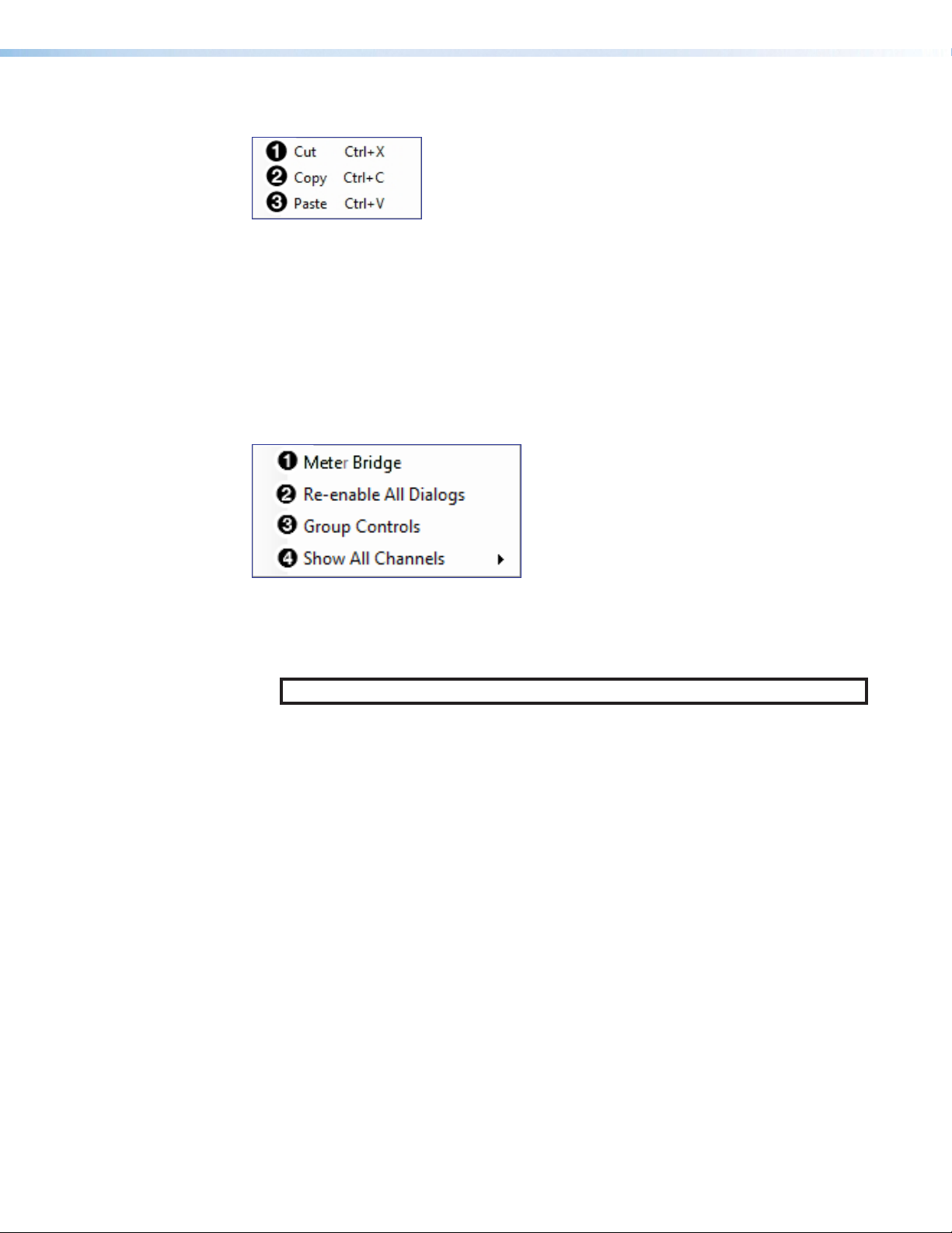
Figure 10. View Menu
Meter Bridge — Opens a meter bridge to view input and output activity. The meter
1
bridge is a floating window, allowing use of the DSP Configurator workspace while
simultaneously monitoring input and output activity.
NOTE: The meter bridge is only available in Live mode with a TCP/IP connection.
Re-enable All Dialogs — This option re-enables all dialog boxes that no longer
2
appear based on user selection (certain dialog boxes that appear are user-defeatable by
selecting a checkbox that reads Do Not Show This Dialog Again).
Group Controls — Opens the Group Controls dialog box to access existing group
3
controls and add new groups.
Show All Channels — Individual channels can be hidden by user selection. This
4
provides options for the user to select which input and output groups are visible in the
main workspace.
XMP 240 C AT • DSP Configurator Software 13
Page 20
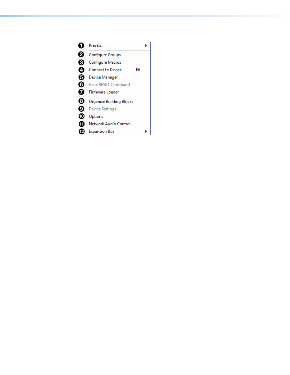
Tools
Figure 11. Tools Menu
Presets — Contains a submenu to mark and clear elements in the main workspace as
1
well as an option to save marked elements to a preset (Presets on page67).
Configure Groups — Opens the Configure Groups dialog box to create, edit, and
2
delete Gain, Mute, Bass, Treble, Loudness, and Meter Groups (Groups on page69).
Configure Macros — Opens the Configure Macros dialog box for creating, editing,
3
and deleting macro functions (Macros on page72).
Connect/Disconnect from Device — When in Emulate mode, this reads Connect to
4
Device and opens the Connect to Device dialog box (Connect to or Disconnect
from Device on page78). When in Live mode, this reads Disconnect from Device
and returns the software to Emulate mode.
Device Manager — Opens the Device Manager dialog box (Device Manager on
5
page76).
Issue RESET Command — Clears the XMP240 of all processors and other configuration
6
settings. This command does not reset general settings such as IP address.
Firmware Loader — Opens the Firmware Loader application, if it is installed (Firmware
7
Loader on page79). Visit www.extron.com to download the software.
Organize Building Blocks – Opens the Organize Building Blocks dialog box (Organize
8
Building Blocks on page82).
Device Settings — Opens the Device Settings dialog box to edit date and time, IP
9
address, DHCP status, and other settings (Device Settings on page83).
Options – Opens the Options dialog box to configure DSP Configurator appearance, default
¢
settings, DSP value defaults, and so on (Options on page87).
Network Audio Control — Opens the Dante Controller application by Audinate for routing
£
audio over a Dante network (Dante Controller on page89).
Expansion Bus — Contains a submenu to show that the XMP 240 is set as the primary unit
¤
(Expansion Bus on page88).
XMP 240 C AT • DSP Configurator Software 14
Page 21
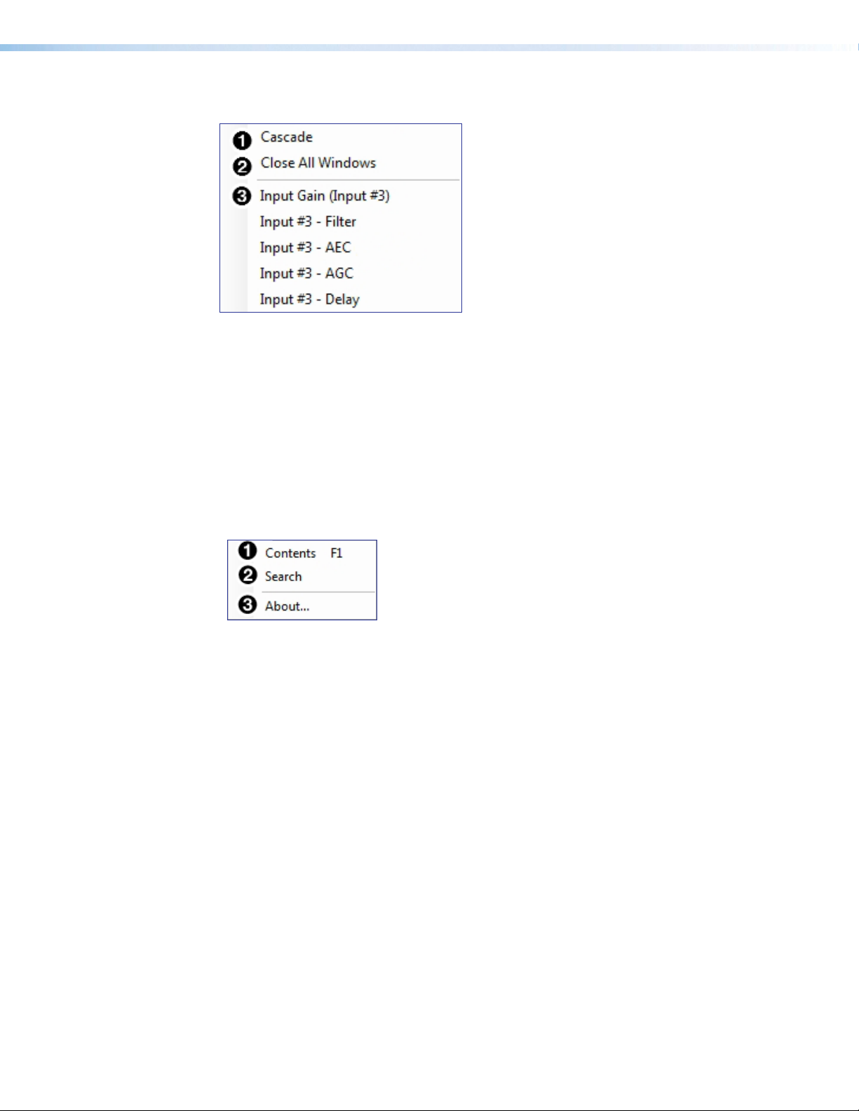
Window
Figure 12. Window Menu
Cascade — Organizes windows by cascading them in the same order they were
1
opened.
Close All Windows — Closes all open windows, leaving only the main workspace
2
visible. When all windows are closed, changes to parameters in the open windows are
saved before the window is closed.
List of Open Windows — Below the dividing line is a list of all open windows. Select
3
a window from the list to bring it into focus and to the forefront of the workspace.
Windows appear in the order they were opened.
Help
Figure 13. Help Menu
Contents — Opens the DSP Configurator Help file where detailed information
1
about DSP Configurator can be found.
Search — Opens the DSP Configurator Help file with the Search field in focus.
2
About — Opens a window displaying software version number, copyright
3
information, and part number for the installed copy of DSP Configurator. Click the
Details button for a list of advanced details, such as build number.
XMP 240 C AT • DSP Configurator Software 15
Page 22
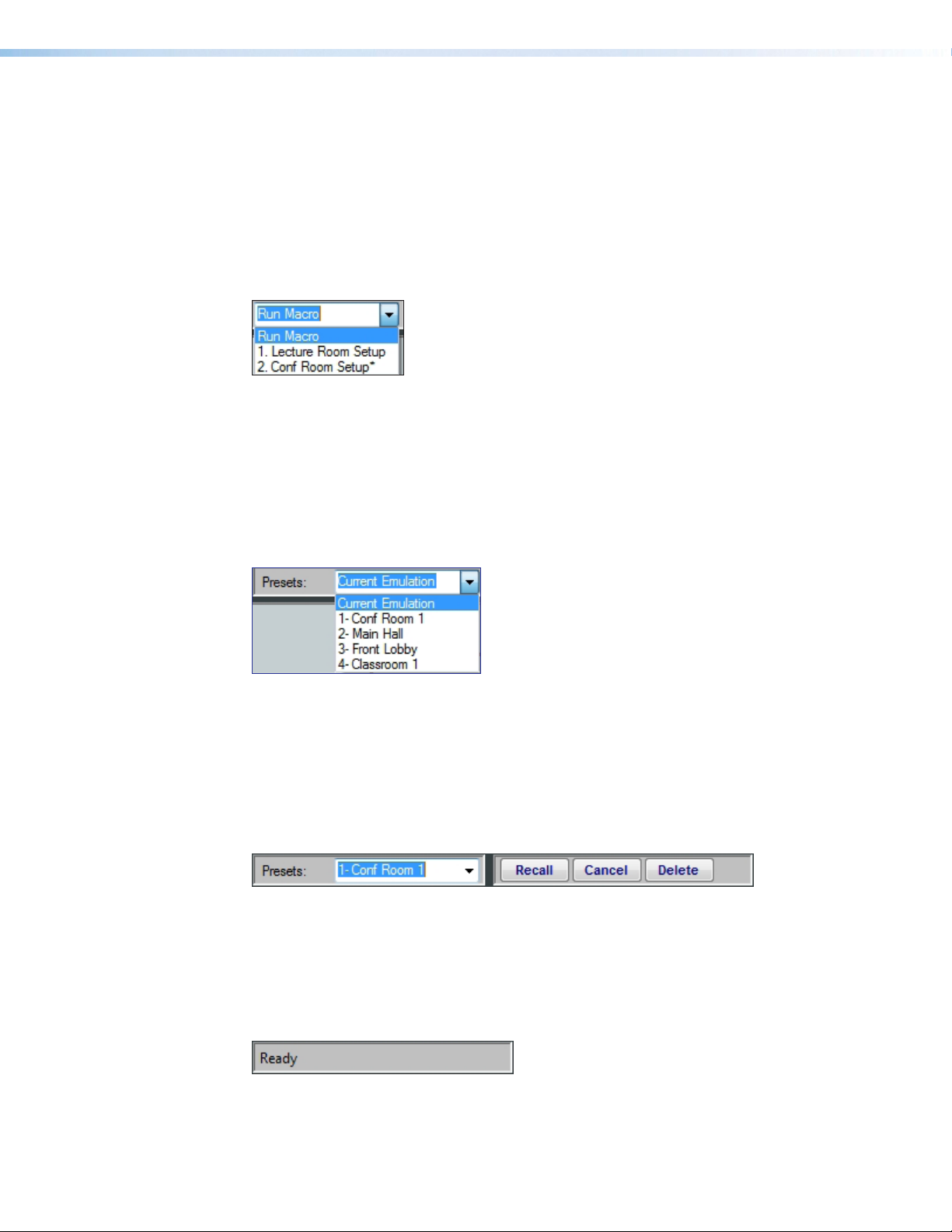
Macros Drop-Down
The Run Macro drop-down menu is available when connected to the XMP240CAT in Live
mode. The drop-down list is unavailable in Emulate mode.
The Run Macro drop-down list allows the user to view and run all macros that have been
pushed to the device. The list of macros updates dynamically when a new macro is created.
Macros created in DSP Configurator that have not been pushed to the device appear in the
list with an asterisk to the right of the macro name. Only macros that have been pushed
to the device can be run from the Run Macro drop-down list (Macros on page72 for
information on configuring macros).
Figure 14. Macros Drop-Down Menu
Presets Drop-Down
The Presets drop-down menu allows the user to view and apply presets saved in the
current configuration file or on a device connected in Live mode. Presets with an asterisk
next to them are on the XMP240CAT, but not in the current configuration file. Run a preset
to load it into the configuration file. Alternatively, perform a backup to run all presets and
load them into the current configuration file (File on page12).
Figure 15. Presets Drop-Down Menu
After selecting a preset from the list, choose one of the following actions from the
DSPConfigurator status panel:
Recall — Recalls the selected preset and applies settings to the main workspace.
Cancel — Cancels the preset recall and returns to the main workspace with the current
emulation or state intact.
Delete — Deletes the selected preset from the configuration.
Figure 16. Preset and Action Selection
DSP Configurator Status Panel
This panel displays the current status of DSP Configurator and shows when data is being
pushed to or pulled from the device. When the software is ready to perform actions, the
panel reads Ready.
Figure 17. DSP Configurator Status Panel
XMP 240 C AT • DSP Configurator Software 16
Page 23
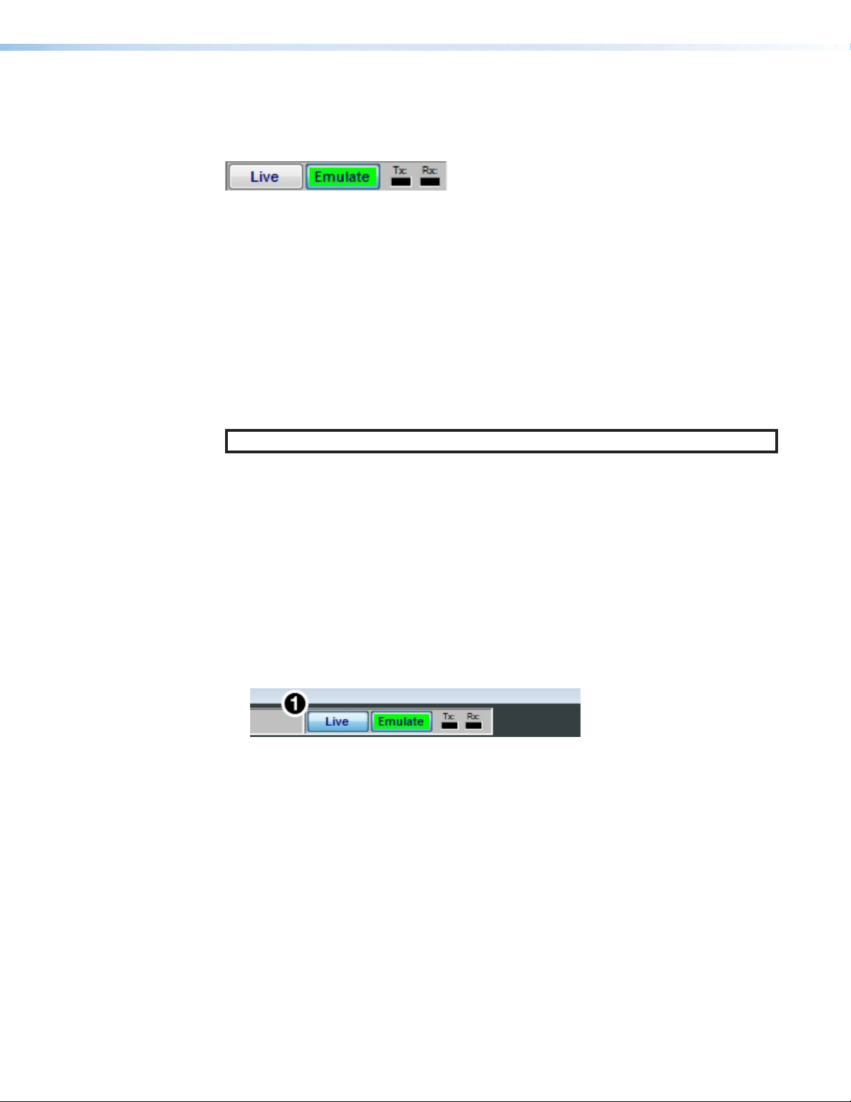
Live and Emulate Panel
The Live and Emulate buttons allow users to switch between Live and Emulate mode and
displays transmit activity (Tx) and receive activity (Rx) when in Live mode.
Figure 18. Mode Panel
Emulate Mode
While in Emulate mode, DSP Configurator is functioning in an “offline” state. Changes made
to the configuration file are not applied to a XMP240CAT.
In Emulate mode, the user can create and configure the software as though a device was
connected, except for any actions that require direct connection to the device or information
that is stored only on the device. Once configuration is complete, the user can switch to
Live mode and apply the configuration to the device or save the configuration file to be
loaded onto one or multiple devices at a later time.
Creating configuration files in Emulate mode saves time by not requiring a device to be
connected or present in order for the bulk of DSP configuration to be completed.
NOTE: Not all menu options or actions are available in Emulate mode.
Live Mode
Enter Live mode to connect to a XMP240CAT and push or pull configurations between the
device and host PC. In Live mode, changes made in DSP Configurator are directly applied
to the XMP240CAT. Additionally, presets and macros can be created and stored on the
device.
When entering Live mode, the user is prompted with the Connect to device dialog box.
Connect to a XMP240CAT in Live Mode
1. Click the Live button in the menu bar of DSP Configurator (see figure 19 , 1).
Alternatively, select Tools > Connect to Device or press <F6> on the keyboard. The
Connect to device dialog box opens.
Figure 19. Live Button
2. Connect to the XMP240CAT.
a. To connect via TCP/IP (recommended):
Click the TCP/IP tab in the dialog box. Enter the IP address of the device in the
Hostname or IP Address field. If necessary, enter the device password in the
Password field (see figure 20,
b. To connect via USB:
Click the USB tab in the dialog box. Select the device from the USB Devices
drop-down menu (b).
c. To connect via RS-232:
Click the RS-232 tab in the dialog box. Select the com port the device is connected
to on the host PC from the Com Port drop-down (c).
on the next page).
a
XMP 240 C AT • DSP Configurator Software 17
Page 24
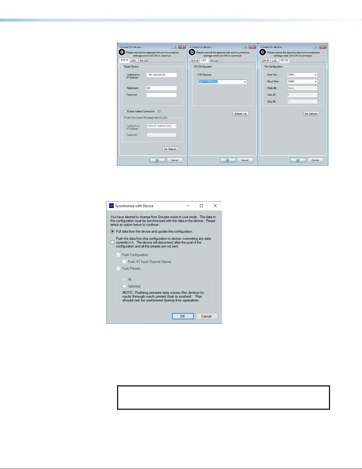
Figure 20. Connect to device... TCP/IP, USB, and RS-232 Dialog Box
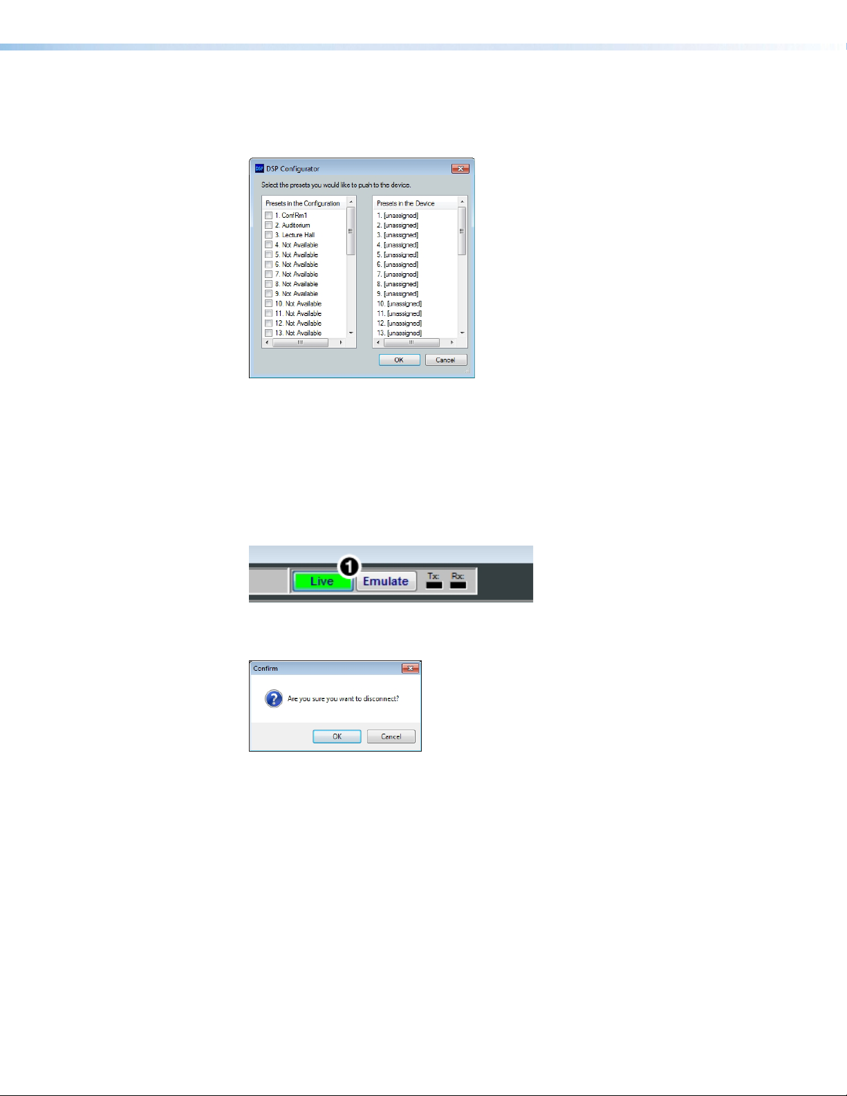
3. When a connection with a device is established, the Synchronize with Device dialog
box opens.
Figure 21. Synchronize with Device Dialog Box
a. Pull — Pulls the configuration file, presets, macros, and ACP configurations from
the device and displays it in the DSP Configurator main workspace.
b. Push — Pushes the configuration file, presets, macros, and ACP configurations
open in DSP Configurator to the connected XMP240.
The check boxes indicate what will be pushed when OK is selected. Pushing a
selected item will overwrite that item on the device.
NOTE: If only pushing selected presets, the preset selection dialog box opens
after clicking OK. This dialog allows you to select which preset to push to the
device.
XMP 240 C AT • DSP Configurator Software 18
Page 25
If only pushing selected presets, select them in the dialog box shown in the figure
below.
Figure 22. Preset Selection Dialog Box
4. Once a push or pull is completed, the current state of the connected XMP240CAT
is displayed in the DSP Configurator status panel and the device is ready for further
configuration.
Exit Live Mode and Enter Emulate Mode
1. Click the Emulate button in the DSP Configurator menu bar (see figure 23, 1).
Alternatively, select Tools > Disconnect from Device or press <F6> on the keyboard.
Figure 23. Emulate Button
2. Click OK to confirm.
Figure 24. Confirm Disconnect
XMP 240 C AT • DSP Configurator Software 19
Page 26
DSP Configurator Inputs
All available inputs are listed vertically along the left side of the DSP Configurator main
workspace. The input groups can be expanded or collapsed by clicking the (expand) or
(collapse) buttons next to the input group names.
There are two types of inputs available:
• Inputs • Virtual Returns
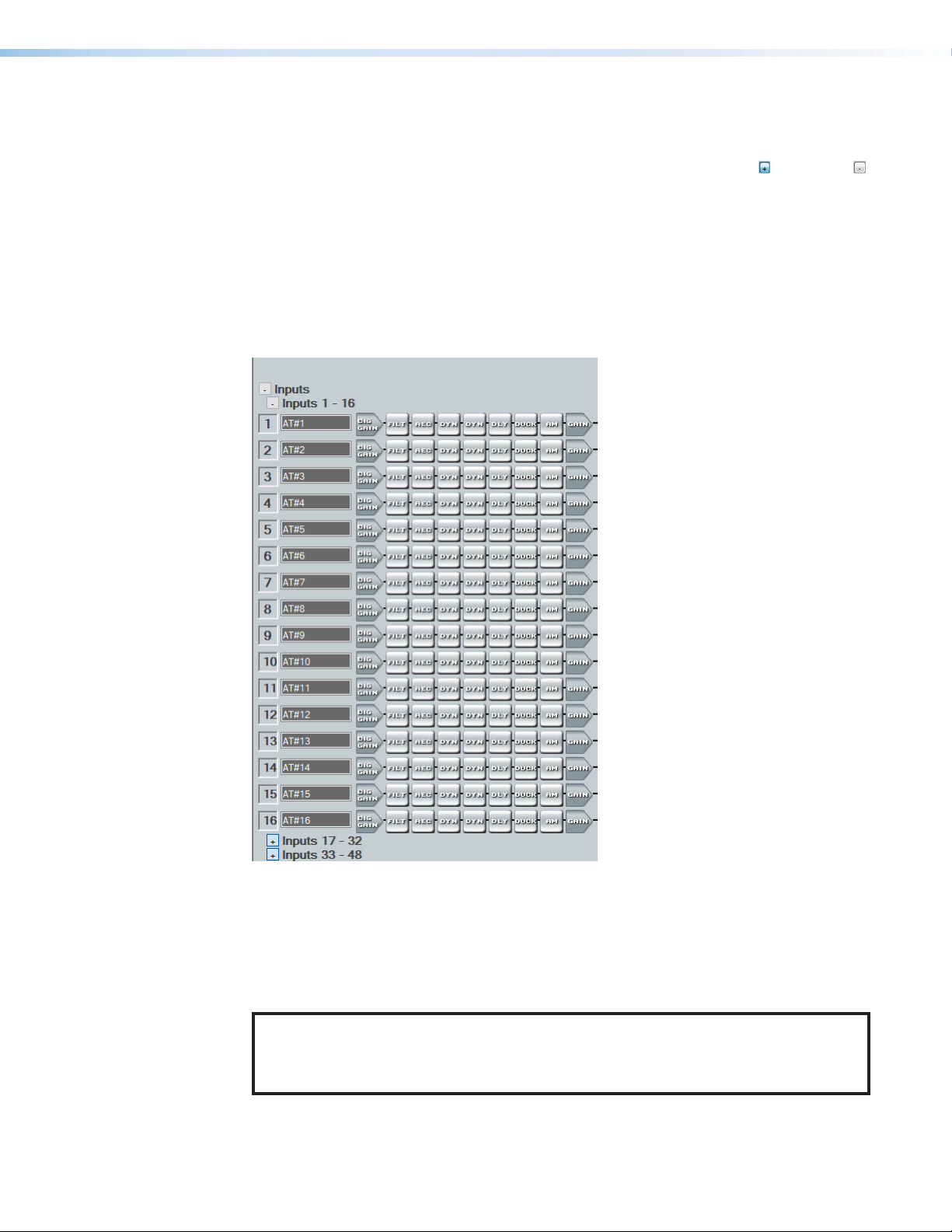
Inputs
The 48 mic/line input channels on the XMP 240 are shown in DSP Configurator under the
Inputs panel.
Figure 25. Inputs
Inputs 1 - 24 offer AEC (Acoustic Echo Cancellation) DSP capability. Inputs 25 - 48 do not
have AEC. The 48 channels of Dante inputs and 16 channels of audio via the EXP port are
available as digital sources for the XMP 240 inputs.
Renaming an Input
NOTE: Renaming an AT input in DSP Configurator affects the receiver name in
DanteController. Alternatively, renaming a receiver channel in Dante Controller affects
the name displayed in DSPConfigurator (see Renaming a Receiver or Transmitter
on page93).
XMP 240 C AT • DSP Configurator Software 20
Page 27
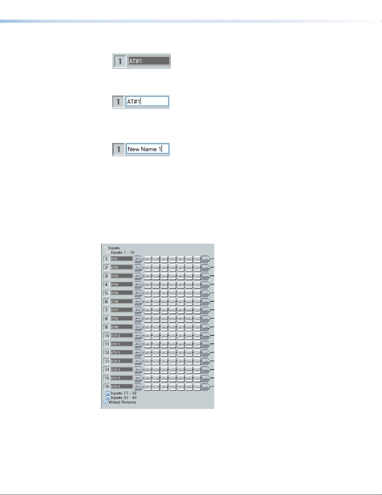
1. Click the expansion or input name field.
2. Delete or highlight the text, and type the desired name.
3. Press the <Enter> key or navigate away from the field to confirm and apply the new
Inputs Overview
With the Extron Expansion Port (EXP), two EXP enabled devices can be connected for
bidirectional communication. When two units are connected, one unit must be set as the
Primary Unit and the other must be set as the Secondary Unit (see Expansion Bus on
page88). This synchronizes the sampling clocks of the two units.
AT inputs allow a XMP240CAT model to receive signal from the audio network. Network
audio routing is done with Dante Controller (see Dante Controller on page89).
Figure 26. Input Name Field
Figure 27. Input Name
name. Press the <Down Arrow> key to navigate to and highlight the next name field.
Figure 28. Renamed Input
Figure 29. AT Inputs
XMP 240 C AT • DSP Configurator Software 21
Page 28
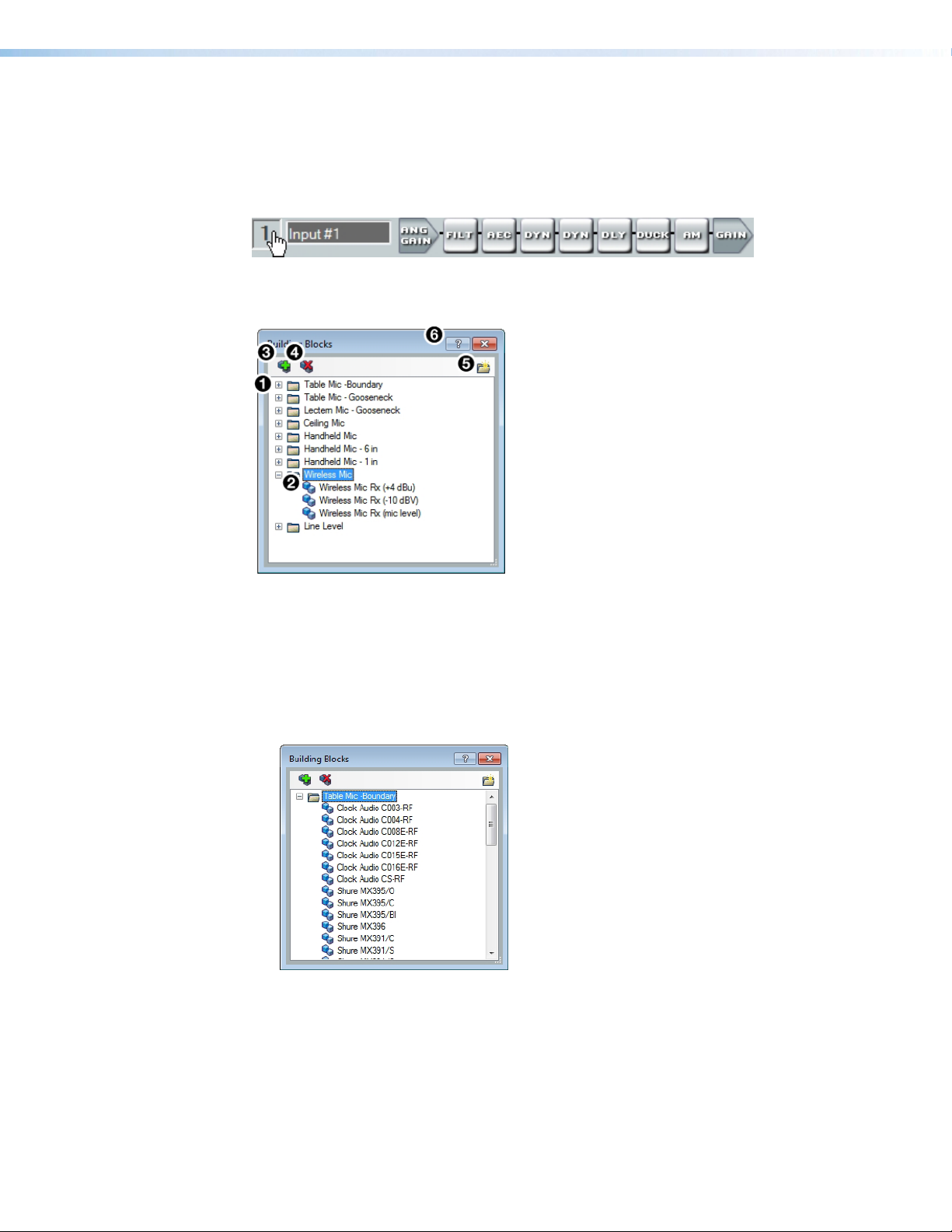
Input Building Blocks
Extron building blocks are a quick configuration tool that can significantly reduce
configuration time. An input building block is a collection of processor and gain settings for
an input processing chain. These building blocks have been designed by Extron based on
extensive use and testing with each intended application or specific device.
Figure 30. Accessing Input Building Blocks
Click the input number (see figure 30) to open the Building Blocks dialog box.
Building Block Folders
1
General Building Blocks
2
Add a Building Block Button
3
Figure 31. Input Building Blocks Dialog Box
Building Block Folders — These folders group input types together, such as table or
1
handheld mics, for easy access (see figure 32).
Figure 32. Mic Building Block Folder Contents
General Building Blocks — These building blocks provide quick setup for input
2
sources. General building blocks provide a useful starting point for devices in the same
product category as the name of the building block, such as handheld microphones,
line level sources, and so on.
Delete a Building Block Button
4
New Folder Button
5
Building Blocks Help Button
6
XMP 240 C AT • DSP Configurator Software 22
Page 29
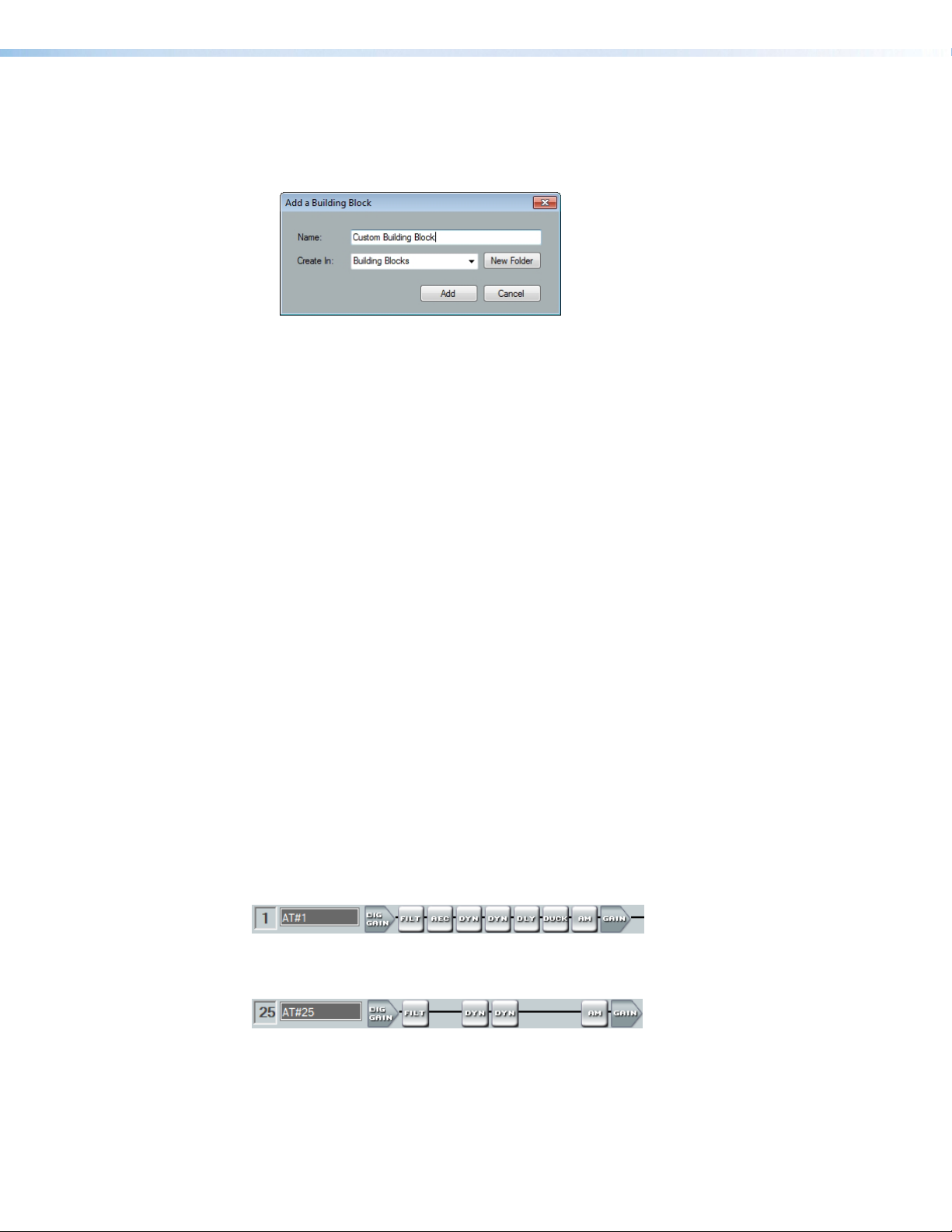
Add a Building Block Button — Creates a custom building block from the current
3
gain and processor settings on the selected channel. When this button is clicked, the
Add a Building Block dialog box opens. Name the new custom building block and
choose a folder to save the block to, or create a new folder (see figure 33).
Figure 33. Add a Building Block Dialog Box
Delete a Building Block Button — Deletes the currently selected building block or
4
building block folder. If default building blocks are deleted, they can be restored from the
Organize Building Blocks dialog box. Custom building blocks can be saved to a file
from the same dialog box (Organize Building Blocks on page82).
New Folder Button —Creates a new folder or sub-folder in the Building Blocks
5
dialog box.
Building Blocks Help Button — Opens the Building Blocks topic of the
6
DSPConfiguratorHelp file. This topic contains more information on the different types
of building blocks for inputs and outputs.
Input Processing
The input processing chain in DSP Configurator is visually represented by a string of
blocks(see figure 34). Each block contains a specific processor or type of processor. For
example, the Input Gain block contains a fader to boost or attenuate incoming signal, the
Filter block contains several types of filters, and so on. Inputs 1 - 24 contain the following
processing chain:
1. Input Gain Block
2. Input Filter Block
3. Input AEC Block
4. Input Dynamics Blocks (2)
5. Input Delay Block
6. Input Ducking Block
7. Input Automix Block
8. Input Pre-Mixer Gain Block
Figure 34. Input 1 - 24 Processing Chain
Inputs 25 - 48 contain the following processing chain:
Figure 35. Input 25 - 48 Processing Chain
XMP 240 C AT • DSP Configurator Software 23
Page 30

Input Gain Block
Double-click the DIG GAIN (Input Gain) block to open the Input Gain dialog box.
Figure 36. Input Gain Block
The Input Gain dialog box provides controls to configure the input gain stage of the input
processing path.
Input Name
1
Gain Fader
2
dBFS Meter
3
dBFS Numeric Readout
4
Input Gain Text Field
5
Polarity Toggle Button
6
Figure 37. Input Gain Dialog Box
Input Name — This name changes to match the default or user defined input name.
1
Gain Fader — Provides up to 24 dB of gain or 18dB of attenuation in 0.1 dB steps.
2
Click the fader once and press the <Up Arrow> or <Down Arrow> keys to adjust the
fader up or down in 1 dB steps. Press the <Page Up> or <Page Down> keys to adjust
the fader up or down in 10 dB steps.
dBFS Meter — This meter displays the input signal level in dBFS ranging from
3
-60dBFS to 0dBFS. Once the signal reaches or passes -1dBFS (default) or the clip
threshold defined in the Options dialog box (Options on page87), the clip box
located at the top of the meter lights red.
dBFS Numeric Readout — This read-only text box displays the numerical value of the
4
input signal level in dBFS.
Input Gain Text Field — This text field allows the user to enter a gain or attenuation
5
value in 0.1 dB steps.
Polarity Toggle Button — Inverts the signal polarity of the selected input. When the
6
button displays the black + symbol on a gray field ( ), the polarity is normal. When the
button displays the black - symbol on a yellow field ( ), the polarity is inverted.
Mute Button — Mutes signal at the input stage, preventing it from going any further in
7
the signal processing chain.
Source Drop-Down Menu — Selects the input audio source for the channel. Source
8
options are any of the 48 AT Inputs or 16 EXP inputs.
OK Button — Confirms changes and closes the Input Gain dialog box.
9
Mute Button
7
Source Drop-Down Menu
8
OK Button
9
Cancel Button
¢
Input Gain Help Button
£
XMP 240 C AT • DSP Configurator Software 24
Page 31

Cancel Button — Reverts any changes made to the contained parameters back to
¢
their states when the current instance of the Input Gain dialog box was opened and
closes the dialog box.
Input Gain Help Button — Opens the Mic/Line Input Gain topic in the
£
DSPConfiguratorHelp file for further assistance in configuring input gain.
Input Filter Block
Double-click the Filter block to open the filter drop-down menu. Select one of the eleven
available filters to insert into the block.
Figure 38. Filter Block and Drop-Down Menu
Alternatively, right-click the Filter block and select Insert, then select a filter to insert it
into the block.
Figure 39. Insert Filter Drop-Down Menu
Once an initial filter is selected, the Filter block changes to display the type of filter applied.
For example, if High Pass Filter is selected, the Filter block would display HIGH PASS
instead of FILT. If multiple filters are applied, the Filter block displays FILT over a dark
green field.
Figure 40. Filter Block Icons
Once a filter is applied to the Filter block, double-click the block to open the Filter
dialog box.
XMP 240 C AT • DSP Configurator Software 25
Page 32

Filter Channel Name
1
Filter Graph
2
Filter List
3
Set Defaults Button
4
Figure 41. Filter Dialog Box
Filter Channel Name — This name changes to match the default or user defined input
1
name.
Filter Graph — Graphically displays the applied filter curve and provides handles for
2
adjusting filter parameters. Numbers along the top of the graph represent the filter curve
of the corresponding slot in the filter list below the graph. The number appears over the
center frequency of the filter.
If a filter is active (unbypassed), it appears as a solid red curve. If a filter is bypassed, it
appears as a broken orange curve (such as the bass filter in slot 2).
NOTE: All filters are bypassed by default.
Filter List — Provides filter drop-down menus for all 5 available filter slots. Frequency,
3
Slope, Boost/Cut, Q, and Bypass controls are also available in this list.
Available filters include:
• High Pass Butterworth • High Pass Linkwitz-Reily
• Low Pass Butterworth • Low Pass Linkwitz-Reily
• Bass • High Pass Bessel
• Treble • Low Pass Bessel
• Parametric • Loudness
• Notch
OK Button
5
Cancel Button
6
Filters Help Button
7
NOTE: See the DSP Configurator Help file for more information on each of the
filters. Click the Filters Help button to open the help file topic discussing filters.
XMP 240 C AT • DSP Configurator Software 26
Page 33

Set Defaults Button — Resets all filter parameters of all filters in the filter list to their
4
default values.
To reset a single filter to default parameters, right-click the filter number on the left side
of the Filter dialog box, and select Set to Default (see figure 42).
Figure 42. Set Single Filter Parameters to Default
OK Button — Confirms changes made to the contained parameters and closes the
5
Filter dialog box.
Cancel Button — Reverts any changes made to the contained parameters back to
6
their states when the current instance of the Filter dialog box was opened and closes
the dialog box.
Filters Help Button — Opens the About Filters topic in the DSPConfiguratorHelp
7
file. This help file topic discusses each filter type in greater detail.
Input AEC Block
About AEC
Echo occurs when audio from a talker in the far end is received and amplified into the near
end listener’s room, with that sound then being picked up by microphones in the near end
acoustic space and sent back to the far end. The amount of signal sent back to the far end
talker can be substantial, and with the added transmission delay, the result is an echo effect
that can seriously compromise communication in a teleconference or videoconference.
The Extron Acoustic Echo Cancellation (AEC) processor removes the potential echo
signal at the near end mic channel by comparing it to the received signal from the far end,
designated as the “reference,” and then creating an adaptive filter to cancel the potential
echo before it is sent back to the far end.
Successful operation of the AEC processing block is mainly a function of proper gain
structure and selection of an AEC reference. This section provides an overview of those two
elements.
Proper gain structure involves the relationship between the signal at the selected reference
and the signal at the mic input, within the context of proper levels for the reference and mic
inputs independently. The mic input gain setting will naturally be optimized for the voice level
of the talker in that room. Therefore, the amount of signal from the far end picked up by the
mic is dependent on how much far end signal is being amplified in the near end room and
the distance from the mic to the speakers.
XMP 240 C AT • DSP Configurator Software 27
Page 34

AEC Operation
Double-click the AEC block to open the AEC drop-down menu. Select AEC to insert the AEC
processor.
Figure 43. AEC Block and Drop-Down Menu
NOTE: Insert the AEC processor on the input with the near end microphone connected.
Once the AEC processor is inserted, double-click the AEC block to open the AEC dialog box.
Activity Panel
1
ERL Meter
2
ERLE Meter
3
TER Meter
4
Reference Selection Drop-Down
5
Noise Cancellation Panel
6
Figure 44. AEC Dialog Box
Activity Panel — Far lights when signal activity is detected from the far end. Near
1
lights when activity is detected from the near end. Update lights when AEC is updating,
converging, or reconverging.
ERL Meter — ERL (echo return loss) is the ratio of the far end signal at the reference
2
input to the far end signal received at the mic input and is expressed in dB. This meter
should read between -10 dB and +10 dB for proper AEC operation.
ERLE Meter — ERLE (echo return loss enhancement) is the amount of potential
3
echo signal that the AEC algorithm is cancelling (not including NLP processing) and is
expressed in dB.
TER Meter — TER (total echo reduction) is the sum of ERL and ERLE and represents
4
the total amount of echo reduction and is expressed in dB.
Bypass Button
7
OK Button
8
Cancel Button
9
Show/Hide Advanced Options Button
¢
AEC Help Button
£
XMP 240 C AT • DSP Configurator Software 28
Page 35

Reference Selection Drop-Down Menu — (See figure 44 on the previous page)
5
Provides all inputs, outputs, and virtual returns for reference selection. When a channel
is selected as the reference, the AEC processor compares the reference channel signal
to the current input channel.
Noise Cancellation Panel — Provides a checkbox to engage the noise canceller
6
(engaged by default) and text field to enter the amount of noise reduction in dB.
Bypass Button — Bypasses the AEC processor. When the button is red, bypass is
7
enabled.
OK Button — Confirms changes made to the contained parameters and closes the
8
AEC dialog box.
Cancel Button — Reverts any changes made to the contained parameters back to
9
their states when the current instance of the AEC dialog box was opened and closes the
dialog box.
Show/Hide Advanced Options Button — Shows or hides the advanced
¢
configuration options for the AEC processor (AEC Advanced Options below).
AEC Help Button — Opens the Acoustic Echo Cancellation topic of the
£
DSPConfiguratorHelp file for further assistance in operating AEC processor.
AEC Advanced Options
The AEC dialog box provides advanced NLP (non-linear processing) options for fine tuning
echo cancellation. These options are hidden by default. Click the Show/Hide Advanced
Options button to access them (see figure 44,
on the previous page).
¢
Enable NLP Checkbox
1
NLP Presets
2
NLP Reduction Parameters
3
Double Talk Echo Reduction
4
Comfort Noise
5
Figure 45. AEC Advanced Options
Enable NLP Checkbox — Checked by default, NLP (non-linear processing) is required
1
to completely remove echo.
NLP Presets — Offers three preset options for NLP parameters.
2
• Soft — Applies soft preset values to the NLP reduction parameters for light echo
cancellation.
• Normal (default) — Applies normal preset values to the NLP reduction parameters
for the widest array of echo cancellation needs.
• Aggressive — Applies aggressive preset values to the NLP reduction parameters
for aggressive echo cancellation.
NLP Reduction Parameters — Provides text boxes for Max NLP Reduction, Attack
3
XMP 240 C AT • DSP Configurator Software 29
Page 36

Time, and Release Time to customize NLP reduction parameters.
Double Talk Echo Reduction — Provides a text box to enter a reduction value (in dB)
4
when double talk occurs. Double talk is when near end talkers and far end talkers are
speaking simultaneously while AEC is engaged.
Comfort Noise Text Box — Provides an ambient noise signal to prevent states of
5
complete silence that may be perceived as a failed or dropped connection. 0 dB is the
default.
Input Dynamics Blocks
Double-click the Dynamics block to open the dynamics drop-down menu.
Figure 46. Dynamics Block and Drop-Down Menu
From the Dynamics drop-down menu, four types of dynamics processors are available.
Select a dynamics processor type to insert it into the Dynamics block.
There are two Dynamics blocks available per mic/line input channel. Each block can be
configured with any of the processor types.
The four types of dynamics processors available are:
• AGC (Automatic Gain Control) on the next page
• Compressor on page32
• Limiter on page33
• Noise Gate on page34
Once a dynamics processor is inserted, double-click the dynamics block icon to open the
corresponding dialog box.
Figure 47. AGC, Compressor, Limiter, and Noise Gate Icons
If a dynamics processor has been inserted and needs to be changed to a different dynamics
processor, right-click the dynamics block, hover over Insert, and select a new processor to
insert it (see figure 48).
XMP 240 C AT • DSP Configurator Software 30
Page 37

Figure 48. Changing Dynamics Processors
AGC (Automatic Gain Control)
Dynamics Channel Name
1
AGC Graph
2
AGC Parameters List and Control
3
Bypass Button
4
Set Defaults Button
5
OK Button
6
Cancel Button
7
Dynamics Help Button
8
Figure 49. AGC Dialog Box
Dynamics Channel Name — This name changes to match the default or user defined
1
input name.
AGC Graph — Graphically displays AGC parameter settings. Parameters can also be
2
adjusted using this graph. Click and drag the yellow lines to adjust the Window parameter.
Click and drag the bottom dot to adjust the Threshold parameter. Click and drag the
middle dot to adjust the Maximum Gain parameter. Click and drag the top dot to adjust
the Target parameter.
AGC Parameters List and Control — Provides text boxes to adjust all AGC
3
parameters. Attack Time, Hold Time, and Release Time also have sliders that adjust
their respective parameters. Click a slider once and use the <Left Arrow> and
<Right Arrow> keys to adjust the respective parameter in 1 ms steps.
Bypass Button — Bypasses the AGC processor. When the button is red, bypass is
4
enabled.
Set Defaults Button — Resets all AGC parameters to their default values. To view
5
individual parameter default values, see the DSP Configurator Help file by clicking the
Dynamics Help button (
OK Button — Confirms changes made to the contained parameters and closes the
6
AGC dialog box.
Cancel Button — Reverts any changes made to the contained parameters back to
7
their states when the current instance of the AGC dialog box was opened and closes the
dialog box.
Dynamics Help Button — Opens the Dynamics Operation topic of the
8
DSPConfiguratorHelp file for further assistance in operating dynamics processors.
) and opening the About Dynamics topic.
8
XMP 240 C AT • DSP Configurator Software 31
Page 38

Compressor
Compressor Channel Name
1
Compressor Graph
2
Compressor Parameter List and Control
3
Bypass Button
4
Set Defaults Button
5
OK Button
6
Cancel Button
7
Dynamics Help Button
8
Figure 50. Compressor Dialog Box
Compressor Channel Name — This name changes to match the default or user
1
defined input name.
Compressor Graph — Graphically displays compressor parameter settings.
2
Parameters can also be adjusted using this graph. Click and drag the dot within the
green area of the graph to adjust the compressor Threshold. Click and drag the dot
outside the green box to adjust the compressor Ratio.
Compressor Parameter List and Control — Lists all configurable parameters for
3
the compressor. Text fields are available to adjust Threshold, Ratio, Attack Time,
Hold Time, and Release Time. Click and drag sliders to adjust Attack Time, Hold Time,
and Release Time. Click a slider once and use the <Left Arrow> and <Right Arrow>
keys to adjust the respective parameter in 1 ms steps. Select the Soft Knee checkbox
to provide a more natural implementation of compression when the signal reaches the
threshold.
Bypass Button — Bypasses the compressor. When the button is red, bypass is
4
enabled.
Set Defaults Button — Resets all compressor parameters to their default values. To
5
view individual parameter default values, see the DSP Configurator Help file by clicking
the Dynamics Help button (8) to open the About Dynamics topic.
OK Button — Confirms changes made to the contained parameters and closes the
6
Compressor dialog box.
Cancel Button — Reverts any changes made to the contained parameters back to
7
their states when the current instance of the Compressor dialog box was opened and
closes the dialog box.
Dynamics Help Button — Opens the Dynamics Operation topic of the
8
DSPConfiguratorHelp file for further assistance in operating dynamics processors.
XMP 240 C AT • DSP Configurator Software 32
Page 39

Limiter
Limiter Channel Name
1
Limiter Graph
2
Limiter Parameter List and Control
3
Bypass Button
4
Set Defaults Button
5
OK Button
6
Cancel Button
7
Dynamics Help Button
8
Figure 51. Limiter Dialog Box
Limiter Channel Name — This name changes to match the default or user defined
1
input name.
Limiter Graph — Graphically displays limiter parameter settings. Parameters can also
2
be adjusted using this graph. Click and drag the dot on the graph to adjust the limiter
Threshold.
Limiter Parameter List and Control — Lists all configurable parameters for the
3
limiter. Text fields are available to adjust Threshold, Attack Time, Hold Time, and
Release Time. Click and drag sliders to adjust Attack Time, Hold Time, and Release
Time. Click a slider once and use the <Left Arrow> and <Right Arrow> keys to adjust
the respective parameter in 1 ms steps. Select the Soft Knee checkbox to provide a
more gradual implementation of limiting when the signal reaches the threshold.
Bypass Button — Bypasses the limiter. When the button is red, bypass is enabled.
4
Set Defaults Button — Resets all limiter parameters to their default values. To view
5
individual parameter default values, see the DSP Configurator Help file by clicking the
Dynamics Help button (
OK Button — Confirms changes made to the contained parameters and closes the
6
Limiter dialog box.
Cancel Button — Reverts any changes made to the contained parameters back
7
to their states when the current instance of the Limiter dialog box was opened and
closes the dialog box.
Dynamics Help Button — Opens the Dynamics Operation topic of the
8
DSPConfiguratorHelp file for further assistance in operating dynamics processors.
) and navigate to the About Dynamics topic.
8
XMP 240 C AT • DSP Configurator Software 33
Page 40

Noise Gate
Noise Gate Channel Name
1
Noise Gate Graph
2
Noise Gate Parameter List and Control
3
Bypass Button
4
Set Defaults Button
5
OK Button
6
Cancel Button
7
Dynamics Help Button
8
Figure 52. Noise Gate Dialog Box
Noise Gate Channel Name — This name changes to match the default or user
1
defined input name.
Noise Gate Graph — Graphically displays noise gate parameter settings. Parameters
2
can also be adjusted using this graph. Click and drag the upper dot to adjust Ratio.
Click and drag the middle dot to adjust Threshold. Click and drag the bottom dot (out of
view at default settings) to adjust Max Attenuation.
Noise Gate Parameter List and Control — Lists all configurable parameters
3
for the noise gate. Text fields are available to adjust Threshold, Max Attenuation,
Ratio, Attack Time, Hold Time, and Release Time. Click and drag the sliders to
adjust Attack Time, Hold Time, and Release Time. Click a slider once and use the
<Left Arrow> and <Right Arrow> keys to adjust the respective parameter in 1 ms
steps.
Bypass Button — Bypasses the noise gate. When the button is red, bypass is
4
enabled.
Set Defaults Button — Resets all noise gate parameters to their default values. To
5
view individual parameter default settings, see the DSP Configurator Help file by clicking
the Dynamics Help button (8) and navigate to the About Dynamics topic.
OK Button — Confirms changes made to the contained parameters and closes the
6
Noise Gate dialog box.
Cancel Button — Reverts any changes made to the contained parameters back to
7
their states when the current instance of the Noise Gate dialog box was opened and
closes the dialog box.
Dynamics Help Button — Opens the Dynamics Operation topic of the
8
DSPConfiguratorHelp file for further assistance in operating dynamics processors.
XMP 240 C AT • DSP Configurator Software 34
Page 41

Input Delay Block
Double-click the Delay block to open the delay drop-down. Click Delay to insert the delay
processor into the block.
Figure 53. Delay Block and Drop-Down Menu
Once a delay processor is inserted into the Delay block, double-click the block to open the
Delay dialog box.
Delay Channel Name
1
Units of Measurement
2
Delay Fader and Text Box
3
Temperature Panel
4
OK Button
5
Set Defaults Button
6
Cancel Button
7
Bypass Button
8
Delay Help Button
9
Figure 54. Delay Dialog Box
Delay Channel Name — This name changes to match the default or user defined input
1
name.
Units of Measurement — Radio buttons change the unit of measurement used by
2
the delay fader and text box. Samples, Milliseconds, Feet, and Meters are available
units of measurement. Values are converted when the unit of measurement is changed.
Changing the unit of measurement does not alter the amount of delay applied to the
signal.
Delay Fader and Text Box — Adjusts the amount of delay applied to the signal. Click
3
and drag the fader up or down to increase or decrease the amount of delay. Click the
fader once and use the <Up Arrow> or <Down Arrow> to adjust delay in 1 sample steps
(or the 1 sample equivalent in milliseconds, feet, or meters). Use the text box below the
fader to input a delay value.
Temperature Panel — Becomes available when using delay in feet or meters.
4
Compensates delay for ambient temperature in the acoustic space. Temperature is not
available when using samples or milliseconds as the unit of measurement.
OK Button — Confirms changes made to the contained parameters and closes the
5
Delay dialog box.
Set Defaults Button — Resets the delay to 4800 samples.
6
Cancel Button — Reverts any changes made to the contained parameters back to
7
their states when the current instance of the Delay dialog box was opened and closes
the dialog box.
Bypass Button — Bypasses the delay. When the button is red, bypass is enabled.
8
Delay Help Button —Opens the Delay Operation topic of the DSPConfiguratorHelp
9
file for further assistance in understanding operating the delay processor.
XMP 240 C AT • DSP Configurator Software 35
Page 42

Input Ducking Block
The duck block contains a ducking processor as well as an adaptive gain processor.
• Ducker (see the next page) — Decreases levels on specified channels when signal is
present above a set threshold on the duck source (trigger).
• Adaptive Gain (see page 38) — Increases levels on specified channels when signal
is present above a set threshold on the adaptive gain source channel (trigger).
Double-click the Duck block to open the drop-down menu where the Ducker and Adaptive
Gain processors can be selected.
Figure 55. Duck Block and Drop-Down Menu
Select Ducker to insert a ducking processor into the duck block. Select Adaptive Gain
to insert an adaptive gain processor into the duck block. Depending on the processor
selected, the duck block displays DUCK for a ducker or AG for adaptive gain.
Figure 56. Ducking Block Icons
If a ducking processor has been inserted and needs to be changed to an adaptive gain
processor, or vice versa, right-click the block and hover over Insert to insert a different
processor (see figure 57).
Figure 57. Changing Ducking Processor
XMP 240 C AT • DSP Configurator Software 36
Page 43

Ducker
After inserting a ducker processor, double-click the Duck icon to open the
Ducker Configuration dialog box.
Duck Source Configuration
1
Duck Parameter Settings
2
Duck Priority Tree
3
Ducking Operation Help Button
4
Figure 58. Ducker Configuration Dialog Box
Duck Source Configuration — The Enable Source Mic/Line checkbox is checked
1
when a ducker is inserted (default). In the Duck column, check the inputs that will be
ducked. In the by (dB) column, enter the amount of ducking that will occur on each
channel selected in the Duck column. When the threshold is exceeded on the duck
source, ducking occurs on the selected channels.
Duck Parameter Settings — Contains controls for setting Threshold, Attack Time,
2
Hold Time, and Release. Click the Ducking Operation Help button (
Ducking Operation topic in the DSP Configurator Help fie.
Duck Priority Tree — Displays the ducking priority for all Input and Aux In channels.
3
Select another input to populate the Ducker Configuration dialog with the ducker
information for that channel. Channels with an adaptive gain processor are appended
with an (AG). Channels with adaptive gain processors cannot be selected from this
dialog box.
Ducking Operation Help Button —Opens the Ducking Operation topic of the
4
DSPConfiguratorHelp file for further assistance in ducker configuration.
) to open the
4
XMP 240 C AT • DSP Configurator Software 37
Page 44

Adaptive Gain
After inserting an adaptive gain processor, double-click the AG icon to open the
Adaptive Gain dialog box.
Adaptive Gain Source Configuration
1
Adaptive Gain Parameter Settings
2
Adaptive Gain Operation Help Button
3
Figure 59. Adaptive Gain Dialog Box
Adaptive Gain Source Configuration — In the Add Gain To column, check the inputs
1
that will have gain added by the adaptive gain processor. In the Max Gain (dB) column,
enter the maximum amount of gain that will be applied to each channel selected in the
Add Gain To column. When a box is checked, gain is applied to that channel when
signal exceeds the threshold on the adaptive gain trigger channel.
NOTE: For every 1 dB of signal beyond the level set in the Threshold field, 1 dB
of gain will be added to the channels selected in the Add Gain To column. This
occurs until the maximum gain set in the Max Gain (dB) field has been applied.
Adaptive Gain Parameter Settings — Contains controls for Threshold, Attack Time,
2
Hold Time, and Release Time.
Adaptive Gain Operation Help Button — Opens the Adaptive Gain Operation topic
3
of the DSPConfiguratorHelp file for further assistance in adaptive gain configuration.
XMP 240 C AT • DSP Configurator Software 38
Page 45

Input Automix Block
Double-click the Automix block to open a drop-down menu. Select Auto-mixer to insert the
automix processor into the block.
Figure 60. Automix Block and Drop-Down
Once the automix processor is inserted into the Automix block, double-click the block to
open the Automix dialog box.
Automix Channel Name
1
AM Group Assignment Panel
2
Show AM Group Details Button
3
Automix Parameters
4
dBFS Meter
5
Gate Status Indicator
6
Monitor Gate Checkbox
7
Set Defaults Button
8
Bypass Button
9
OK Button
¢
Cancel Button
£
Automix Help Button
¤
Figure 61. Automix Dialog Box
Automix Channel Name — This name changes to match the default or user-defined
1
input name.
AM Group Assignment Panel — Provides nine radio buttons to assign the current
2
automix processor to an AM (automix) group. The default is None and leaves the
automixer unassigned.
Show AM Group Details Button — Opens the Automix Groups dialog box (click the
3
Automix Help button for more information regarding Automix Groups).
Automix Parameters — Provides configuration controls for all automix parameters.
4
dBFS Meter — Displays the post-automix signal level.
5
Gate Status Indicator — This LED lights when monitoring is enabled and the gate is
6
open.
Monitor Gate Checkbox — Click the Monitor Gate checkbox to enable SIS
7
responses regarding gate status (see Automixer Gate Monitoring on the next page).
Set Defaults Button — Resets all automix parameters to their default settings.
8
Bypass Button — Bypasses the automix processor. When the button is red, bypass is
9
enabled.
OK Button — Confirms changes made to the contained parameters and closes the
¢
Automix dialog box.
XMP 240 C AT • DSP Configurator Software 39
Page 46

Cancel Button — Reverts any changes made to the contained parameters back to
£
their states when the Automix dialog box was opened and closes the dialog box.
Automix Help Button — Opens the Automix topic of the DSPConfiguratorHelp file for
¤
further assistance in configuring the automix processor.
Automixer Gate Monitoring
Automixer gate monitoring allows the user to track when an automixer gate opens or
closes. This feature can be enabled by checking the Monitor Gate checkbox in an Automix
dialog (figure 61, 7 on the previous page). When automixer gate monitoring is enabled
for a channel, an unsolicited message is sent when the gate has opened or closed. The
response will include the Automixer OID, gate open or closed status, and the signal level
immediately after the status has changed (see Automixer Gate Monitoring on page125
for SIS response syntax).
Comparing the automixer gate threshold setting to the gate status in the response will
indicate whether the automixer gate has opened or closed. When the gate status in the
response is 1024 or greater, the gate has opened, and when the gate status in the response
is less than 1024, the gate has closed.
Input Pre-Mixer Gain Block
Double-click the pre-mixer Gain block to open the Pre-mixer Gain dialog box.
Figure 62. Input Pre-mixer Gain Block
The Pre-mixer Gain dialog box provides controls to boost, attenuate, and mute the signal
after input processing occurs and before it is sent to the mix matrix.
Input Name
1
Pre-mixer Gain Fader
2
Pre-mixer Gain Text Box
3
Mute Button
4
OK Button
5
Cancel Button
6
Pre-mixer Gain Help Button
7
Figure 63. Input Pre-mixer Gain Dialog Box
Input Name — This name changes to match the default or user defined input name.
1
XMP 240 C AT • DSP Configurator Software 40
Page 47

Virtual Returns
Pre-mixer Gain Fader — Click and drag the gain fader to provide up to 12 dB of
2
gain or 100dB of attenuation in 1 dB steps. Click the fader and use the <Up Arrow> or
<Down Arrow> keys to adjust the fader up or down in 1 dB steps.
Pre-mixer Gain Text Box — Enter a gain or attenuation value in 0.1 dB steps.
3
Mute Button — Mutes signal at the pre-mixer stage, preventing it from reaching the
4
mix matrices.
OK Button — Confirms changes made to the contained parameters and closes the
5
Pre-mixer Gain dialog box.
Cancel Button — Reverts any changes made to the contained parameters back to
6
their states when the current instance of the Pre-mixer Gain dialog box was opened
and closes the dialog box.
Pre-mixer Gain Help Button — Opens the Pre-mixer Gain topic of the
7
DSPConfiguratorHelp file for further assistance in understanding operating the
Pre-mixer Gain dialog.
Virtual returns receive signal when inputs are routed to the virtual send bus (see Virtual
Send Bus on page55). Sixteen virtual return channels are available and are labeled A
through P. These channels can be used in a number of applications. For example, they can
act as an AEC reference channel or be used for sub-mix processing.
Figure 64. Virtual Returns Input Panel
XMP 240 C AT • DSP Configurator Software 41
Page 48

Renaming a Virtual Return
1. Click the virtual return name field.
Figure 65. Virtual Return Name Field
2. Delete or highlight the text and type the desired name.
Figure 66. New Virtual Return Name
3. Press the <Enter> key or navigate away from the field to confirm and apply the new
name. Press the <Down Arrow> key to navigate to and highlight the next name field.
Figure 67. Renamed Virtual Return
Virtual Return Building Blocks
Building blocks can be applied to all 16 virtual return channels (see Input Building Blocks
on page22 for more information on configuring virtual return building blocks).
Virtual Return Processing
Virtual returns A through H contain the following signal processing chain:
1. Virtual Return Feedback Suppressor Block
2. Virtual Return Filter Block
3. Virtual Return Dynamics Block
4. Virtual Return Delay Block
5. Virtual Return Pre-Mixer Gain Block
Virtual returns I through P contain the following signal processing chain:
1. Virtual Return Filter Block
2. Virtual Return Dynamics Block
3. Virtual Return Delay Block
4. Virtual Return Pre-Mixer Gain Block
NOTE: Only Virtual Return channels A through H contain Feedback Suppression
processing blocks.
XMP 240 C AT • DSP Configurator Software 42
Page 49

Virtual Return Feedback Suppressor Block
Use the feedback suppressor when there is an indication of feedback during live operation.
Dynamic filters automatically detect feedback on a live mic channel, and engage a set of
up to 5 fixed and 15 dynamic filters to counteract feedback at the detected frequencies.
The dynamic filters act in a “first in, first out” rotation. If all 15 dynamic filters are employed
and an additional feedback frequency is detected, the first feedback frequency detected is
overwritten.
To avoid a new feedback frequency overwriting a previously detected frequency, up to 5
dynamic filters can be transferred into fixed filters. Once a dynamic filter is transferred into a
fixed filter, it can only be overwritten by manually assigning a new frequency to the filter.
Double-click the feedback suppressor block to show the feedback suppressor drop-down
menu. Select Feedback Suppressor to insert a feedback suppressor processor into the
signal chain.
Figure 68. Feedback Suppressor Block and Drop-Down Menu
After inserting the feedback suppressor in the signal chain, double-click the FBS block to
open the Feedback Suppressor dialog box.
Feedback Suppressor Dialog Box
The Feedback Suppressor dialog box contains three tabs for configuring feedback
suppression.
• Settings Tab on the next page
• Dynamic Filters Tab on page45
• Fixed Filters Tab on page46
XMP 240 C AT • DSP Configurator Software 43
Page 50

Settings Tab
Settings Tab
1
Composite View Panel
2
Filter Graph
3
Q Adjustment Panel
4
Attack Time Panel
5
Hold Time Panel
6
Bypass FBS Button
7
Set Defaults Button
8
OK Button
9
Cancel Button
¢
Figure 69. Feedback Suppressor Dialog Box - Settings Tab
Settings Tab — Provides access to the global FBS settings.
1
Composite View Panel — Three radio buttons control which filters are displayed in the
2
filter graph:
• Only Dynamic FBS Filters
• Only Fixed FBS Filters
• Fixed & Dynamic FBS Filters (default)
Filter Graph — Displays the dynamic filters, fixed filters, or both, as selected in the
3
Composite View panel.
Q Adjustment Panel — Adjust the default Q parameter of the dynamic filters using the
4
text box or the up/down spinner controls.
Attack Time Panel — Adjust the default Attack Time for dynamic filters.
5
Hold Time Panel — Provides an Enable checkbox, that enables the Hold Time
6
parameter. Entering a time into the Hold Time text boxes sets how long each dynamic
filter will hold before removing the filter.
Bypass FBS — Turns off feedback detection when bypass is engaged (button is red
7
when bypass is engaged). Only the dynamic filters are bypassed. Fixed filters remain
active.
Set Defaults Button — Resets parameters on all tabs to their default values and
8
positions.
OK Button — Confirms changes made to the contained parameters and closes the
9
Feedback Suppressor dialog box.
Cancel Button — Reverts any changes made to the contained parameters back to
¢
their states when the current instance of the Feedback Suppressor dialog box was
opened and closes the dialog box.
XMP 240 C AT • DSP Configurator Software 44
Page 51

Dynamic Filters Tab
Dynamic Filters Tab
1
Dynamic Filters List
2
Move to Fixed Button
3
Clear Button
4
Clear All Button
5
Lock Button
6
Bypass FBS
7
Set Defaults Button
8
OK Button
9
Cancel Button
¢
Figure 70. Feedback Suppressor Dialog Box - Dynamic Filters Tab
Dynamic Filters Tab — Provides access to dynamic filter configuration options.
1
Dynamic Filters List — Displays a list of 15 dynamic feedback suppression filters.
2
As feedback is detected on the virtual return channel, dynamic filters are applied to
suppress feedback with the Q parameter defined in the Settings tab.
Move to Fixed Button — Transfers the dynamic filter along with its current parameters
3
to the Fixed Filters tab, allowing parameters to be edited. This frees up a filter slot in
the Dynamic Filters list.
Clear Button — Clears the dynamic filter and contained parameters.
4
Clear All Button — Clears all dynamic filters and resets the feedback detection and
5
suppression process.
Lock Button — Locks current dynamic filters and prevents more dynamic filters from
6
being applied.
Bypass FBS Button — Bypasses the FBS processor. When the button is red, FBS is
7
bypassed.
Set Defaults Button — Resets parameters on all tabs to their default values and
8
positions.
OK Button — Confirms changes made to the contained parameters and closes the
9
Feedback Suppressor dialog box.
Cancel Button — Reverts any changes made to the contained parameters back to
¢
their states when the current instance of the Feedback Suppressor dialog box was
opened and closes the dialog box.
XMP 240 C AT • DSP Configurator Software 45
Page 52

Fixed Filters Tab
Fixed Filters Tab
1
Fixed Filters List
2
Filter Parameters
3
Single Filter Bypass Button
4
Clear All Button
5
Bypass FBS Button
6
Set Defaults Button
7
OK Button
8
Cancel Button
9
Feedback Suppressor Help Button
¢
Figure 71. Feedback Suppressor Dialog Box - Fixed Filters Tab
Fixed Filters Tab — Provides access to fixed filter configuration options.
1
Fixed Filters List — Displays up to 5 fixed feedback suppression filters.
2
Filter Parameters — Configure the Frequency, Boost/Cut, and Q parameters for each
3
fixed filter using the text boxes.
Single Filter Bypass Button — Bypasses only the filter associated with that filter slot.
4
When the button is red, the filter is bypassed.
Clear All Button — Clears all fixed filters from the list.
5
Bypass FBS Button — Bypasses the FBS processor. When the button is red, FBS is
6
bypassed.
Set Defaults Button — Resets parameters on all tabs to their default values and
7
positions.
OK Button — Confirms changes made to the contained parameters and closes the
8
Feedback Suppressor dialog box.
Cancel Button — Reverts any changes made to the contained parameters back to
9
their states when the current instance of the Feedback Suppressor dialog box was
opened and closes the dialog box.
Feedback Suppressor Help Button — Opens the Feedback Suppressor topic of the
¢
DSPConfiguratorHelp file for further assistance in understanding and operating the
feedback suppression processor.
XMP 240 C AT • DSP Configurator Software 46
Page 53

Virtual Return Filter Block
One filter block is available for each virtual return channel. This filter block functions the
same as the mic/line input filter block (see Input Filter Block on page25 for information
on configuring the virtual return filter block).
Virtual Return Dynamics Block
One dynamics block is available for each virtual return channel. This block functions the
same as the mic/line input dynamics block (see Input Dynamics Blocks on page30 for
information on configuring the virtual return dynamics block).
Virtual Return Delay Block
One delay block is available for each virtual return channel. This block functions the same
as the mic/line input delay block (see Input Delay Block on page35 for information on
configuring the virtual return delay block).
Virtual Return Pre-Mixer Gain Block
The virtual return pre-mixer gain block functions the same as the mic/line input pre-mixer
gain block (see Input Pre-Mixer Gain Block on page40 for information on configuring
the virtual return pre-mixer gain block).
Mix-Points
DSP Configurator contains twelve mix matrices that connect all inputs and outputs (see
figure 72 on page48). The mix matrices set post-processing mix levels.
Each input is connected to a mix-point for the signal to be routed to an output. In general,
mix levels are set relative to each other, achieving a blend of input signals at an optimal
output level, close to, but not exceeding 0 dBFS at the output.
NOTE: In order for mix-points to appear in the workspace, the input group sending
signal to the mix-point must be expanded and the input channel must be visible.
XMP 240 C AT • DSP Configurator Software 47
Page 54

Figure 72. DSP Configurator Mix Matrices Part 1
XMP 240 C AT • DSP Configurator Software 48
Inputs to AT Outputs
1
Inputs to Virtual Sends
2
Page 55

Figure 73. DSP Configurator Mix Matrices Part 2
Mix-Point Dialog Box
Double-click a mix-point to open the Mix-point dialog box. Alternatively, highlight a
mix-point with a single click and press the <Enter> key to open the Mix-point dialog box.
Mix-point Input and Output
1
Mix-point Fader
2
Level Text Box
3
Mute Button
4
Mix Dot Selection
5
OK Button
6
Cancel Button
7
Virtual Returns to
3
Outputs
Virtual Returns to
4
Virtual Sends
Figure 74. Mix-point Dialog Box
Mix-point Input and Output — Displays which input (top) and output (bottom) the
1
mix-point is connecting.
Mix-point Fader — Click and drag the mix-point fader to provide up to 12 dB of gain
2
or 100 dB of attenuation in 1 dB steps. Click the fader and use the <Up Arrow> or
<Down Arrow> keys to change the level in 1 dB steps.
Level Text Box — Allows specific level values to be entered in 0.1 dB steps.
3
Mute Button — Mutes the mix-point (muted by default). When the button is red, the
4
mix point is muted.
Mix Dot Selection — Three radio buttons provide options to choose the type of input
5
processing applied to the mix-point.
NOTE: Mix dot selections are not available on Virtual Returns.
OK Button — Confirms changes made to the contained parameters and closes the
6
Mix-point dialog box.
Cancel Button — Reverts any changes made to the contained parameters back to
7
their states when the current instance of the Mix-Point dialog box was opened and
closes the dialog box.
XMP 240 C AT • DSP Configurator Software 49
Page 56

Mix-Point Context Menu
Right-click a mix-point to open the mix-point context menu. This menu provides quick
options to operate mix-points.
Figure 75. Mix-Point Context Menu
Mute — Mutes the mix-point.
1
Unmute — Unmutes the mix-point and creates an audio path between an input and
2
output.
Bypass Automixer — Bypasses automixer processing at the mix-point and marks the
3
mix-dot blue to signify automixing is bypassed.
Include Automixer — Includes automixer processing at the mix-point and marks the
4
mix-dot orange to signify automixing is included.
Bypass Processors (*Except filter block) — Bypasses signal processing, except
5
for filters, at the mix-point and marks the mix-dot green to signify signal processing is
bypassed.
Cut — Cuts the mix-point parameter configuration, preparing it to be pasted to another
6
mix-point. The parameter configuration information is not removed until it is pasted to
another mix-point.
Copy — Copies the mix-point parameter configuration, leaving the mix-point intact and
7
preparing it to be pasted to another mix-point.
Paste — Pastes a previously cut or copied mix-point parameter configuration to the
8
selected mix-point.
Delete — Deletes the mix-point parameter configuration and mutes the mix-point.
9
Mark Row — Marks the entire row containing the selected mix-point, highlighting all of
¢
the elements.
Unmark Row — Unmarks the entire row containing the selected mix-point.
£
DSP Configurator Outputs
The outputs run along the top right of the main workspace in DSP Configurator. These
outputs receive signal when mix-point connections are made between an input and an
output in the mix-matrices.
Each output panel can be expanded or collapsed by clicking the (expand) or (collapse)
buttons.
XMP 240 C AT • DSP Configurator Software 50
Page 57

Outputs
Naming an Output
There are 48 AT and Expansion outputs are available in the Outputs panel. Signals routed to
these outputs can also be transmitted onto the Dante network.
Figure 76. Outputs Panel
1. Click the output name field.
Figure 77. Output Name Field
2. Delete the text and type the desired output name.
Figure 78. New Output Name
3. Press the <Enter> key or navigate away from the field to confirm and apply the new
output name. Press the <Down Arrow> key to navigate to and highlight the next name
field.
Figure 79. Renamed Output
NOTE: Follow the same procedure to edit an Output name.
Output Building Blocks
Extron building blocks are a quick configuration tool that can significantly reduce
configuration time. A building block is a collection of processor and gain settings for an
input or output processing chain. These building blocks have been built by Extron based on
extensive use and testing with each intended application or specific device.
Figure 80. Accessing Building Blocks on an Output
XMP 240 C AT • DSP Configurator Software 51
Page 58

Click the output number to open the Building Blocks dialog box.
Output Building Blocks List
1
Add a Building Block Button
2
Delete a Building Block Button
3
New Folder Button
4
Building Blocks Help Button
5
Figure 81. Output Building Blocks Dialog Box
Output Building Blocks List — Contains building blocks for output channels.
1
Add a Building Block Button — Allows users to create custom building blocks,
2
saving the currently applied gain and processor settings on the selected channel. Click
the icon to open the Add a Building Block dialog box. This allows users to name the
new custom building block and choose the folder to save the block to an existing folder,
or create a new folder.
Figure 82. Add a Building Block Dialog Box
Delete a Building Block Button — Deletes the currently selected building block or
3
building block folder. If default building blocks are deleted, they can be restored from the
Organize Building Blocks dialog box.
New Folder Button —Creates a new folder or sub-folder.
4
Building Blocks Help Button — Opens the Building Blocks topic of the
5
DSPConfiguratorHelp file. This topic contains more information on the different types
of building blocks for inputs and outputs.
XMP 240 C AT • DSP Configurator Software 52
Page 59

Output Processing
The output processing chain in DSP Configurator is represented by a string of blocks (see
figure 83). Each block contains a specific processor or type of processor. Each output
contains the following processor chain:
1. Output Trim Block
2. Output Delay Block
3. Output Filter Block
4. Output Dynamics Block
5. Output Attenuation Block
Figure 83. Output Processing Chain
Output Trim Block
Double-click the output Trim block to open the Post-mixer Trim dialog box.
Figure 84. Output Trim Block
The Post-mixer Trim dialog box provides pre-processing gain and attenuation control for
the selected output.
Output Name
1
Post-mixer Trim Fader
2
Post-mixer Trim Text Box
3
OK Button
4
Cancel Button
5
Figure 85. Post-mixer Trim Dialog Box
Output Name — This name changes to match the default or user defined output name.
1
Post-mixer Trim Fader — Click and drag the trim fader to provide up to 12 dB of gain
2
or 12dB of attenuation in 0.1 dB steps. Click the trim fader and use the <Up Arrow> or
<Down Arrow> to adjust the fader up or down in 0.1 dB steps.
Post-mixer Trim Text Box — Allows the user to enter a gain or attenuation value in
3
0.1 dB steps.
OK Button — Confirms changes made to the contained parameters and closes the
4
Post-mixer Trim dialog box.
Cancel Button — Reverts any changes made to the contained parameters back to
5
their states when the current instance of the Post-mixer Trim dialog box was opened
and closes the dialog box.
XMP 240 C AT • DSP Configurator Software 53
Page 60

Output Delay Block
One delay block is available for each output channel. This block functions the same as
the mic/line input delay block (see Input Delay Block on page35 for information on
configuring the output delay block).
Output Filter Block
One filter block is available for each output channel. This filter block functions the same as
the input filter block, except that there are 10 slots for filters instead of 5 (see Input Filter
Block on page25 for information on configuring output filters).
Output Dynamics Block
One dynamics block is available for each output channel. This block functions the same as
the input dynamics block (see Input Dynamics Blocks on page30 for information on
configuring the output dynamics block).
Output Attenuation Block
Double-click the output Attenuation block to open the Attenuation dialog box.
Figure 86. Output Attenuation Block
The Attenuation dialog box provides attenuation control for the selected output.
Output Name
1
Output Attenuation Fader
2
Output Attenuation Text Box
3
dBFS Meter
4
dBFS Text Readout
5
Figure 87. Attenuation Dialog Box
Output Name — This name changes to match the default or user defined output name.
1
Output Attenuation Fader — Click and drag the trim fader to provide up to 100dB of
2
attenuation. Click the trim fader and use the <Up Arrow> or <Down Arrow> to adjust the
fader up or down in 1 dB steps.
Output Attenuation Text Box — Allows the user to enter a gain or attenuation value in
3
0.1 dB steps.
dBFS Meter — Provides post-attenuation and pre-mute a readout of the output signal
4
level.
Polarity Button
6
Mute Button
7
OK Button
8
Cancel Button
9
XMP 240 C AT • DSP Configurator Software 54
Page 61

5
6
7
8
9
Virtual Send Bus
The virtual send bus consists of mix points that allow inputs to be routed back to the virtual
return input panel for additional mixing and processing (see Virtual Returns on page41).
dBFS Text Readout — Displays a numerical readout of the output signal level.
Polarity Button — Click this button to invert the signal polarity of the selected output.
When the button displays the black + symbol on a gray field ( ), the polarity is normal.
When the button displays the black - symbol on a yellow field ( ), the polarity is
inverted.
Mute Button — Mutes the signal at the output stage.
OK Button — Confirms changes made to the contained parameters and closes the
Attenuation dialog box.
Cancel Button — Reverts any changes made to the contained parameters back to
their states when the current instance of the Attenuation dialog box was opened and
closes the dialog box.
NOTE: Virtual Send Bus mix-points are highlighted in green.
Figure 88. Virtual Send Bus Mix Points
Virtual Send channels cannot be routed to themselves. For example, Virtual Return A
may be routed to Virtual Return B via the virtual send bus, but Virtual Return A cannot
be routed to itself via the virtual send bus, and so on (see figure 89).
Figure 89. Virtual Send Bus for Virtual Returns
XMP 240 C AT • DSP Configurator Software 55
Page 62

Configuration Tools
This section contains information for configuring certain tools and options that are found
under the Tools menu in DSP Configurator and covers the following topics:
• Presets • Firmware Loader
• Groups • Organize Building Blocks
• Macros • Device Settings
• Connect to or Disconnect from Device • Options
• Device Manager • Expansion Bus
Presets
Preset options are available from the Tools menu.
Figure 90. Presets Options
Mark All Items — Marks all gain blocks, processor blocks, and mix-points in the main
1
workspace. Performing this function before saving a preset ensures every element in the
workspace is saved to the preset.
Save Preset — Saves the marked blocks and mix points of the current configuration
2
as a preset. When Save Preset is clicked, the following dialog box opens saying that
only the elements marked with a green outline are saved to the preset (see figure 91).
This option is only available if items are marked.
Figure 91. Preset Save Message
Clear Marked Items — Unmarks all currently marked elements.
3
XMP 240 C AT • Configuration Tools 67
Page 63

Methods for Marking Items
Marked items are highlighted in green (see figure 92). There are four ways to mark items in
DSP Configurator:
• Mark All — Press <Ctrl+A> on the keyboard to mark all items in the main workspace.
• Mark Group — Click and drag the cursor to create a box around a group of items
to mark them. Click and drag the cursor while holding the <Shift> key to create box
around another group of items to mark them while keeping previous group marked.
• Mark Series — Click the first item in the series to mark it, then press <Shift+Click> on
the final item in the series. All items between the first and last items are marked.
• Mark Multiple Individual – Click the first item to mark it and press <Ctrl+Click> to
mark additional items anywhere in the main workspace.
Figure 92. Marked Items Highlighted in Green
Configuring Presets
1. Create a configuration to be saved as a preset (see DSP Configurator Software on
page10).
2. Mark the items that will be included in the preset.
3. Select Tools > Presets > Save Preset.
4. From the Save a Preset dialog box, enter the preset number (1 through 32) in the
Preset Number field (see figure 93,
assigned read [unassigned]. Enter a name into the Preset Name field (2, 12 character
maximum).
5. Click OK (3) to save the preset.
). Preset slots that do not already have a preset
1
Figure 93. Save a Preset Dialog Box
NOTE: When a configuration file is pushed to a XMP240CAT, presets contained
within that file are available for recall from DSP Configurator or SIS commands.
6. The preset is saved and is available from the Presets drop-down menu at the top of the
main workspace.
Figure 94. Presets Drop-Down
XMP 240 C AT • Configuration Tools 68
Page 64

Groups
Groups allow master control of Gain, Mute, Bass, Treble, Loudness and Meter for groups of
channels. Groups are used in macros and other control configurations.
Click Tools > Configure Groups to open the Configure Groups dialog box.
Select Group
1
Select Control Type
2
Available Group Members
3
Change Name Button
4
Figure 95. Group Controls Dialog Box
Select Group — Provides a drop-down menu to select the number of the group to
1
be configured. If the group has been configured and named, the group name appears
next to the group number. If the group slot is empty, it reads <empty> next to the group
number. There are 64 group slots available.
Select Control Type — Group controls can manage Gain, Mute, Bass, Treble,
2
Loudness, or Meter for the specified inputs, mix-points, or outputs. From the Select
Control Type panel, select the type of control from the Gain, Mute, Bass, Treble, or
Treble lists.
NOTE: Bass and Treble are only available if the Bass and Treble filters are inserted
on a channel and only allow channels with the filters to be placed in a group.
Available Group Members — This section populates according to the selected
3
control type and lists all inputs, mix-points, and outputs available to be added as group
members. Check the box next to a member to add it to the group. Group members
must be the same control type. The maximum number of group members for a single
group is 128.
NOTE: Loudness processors can be selected from input and output gain stages.
Apply Button
5
Delete Current Group Button
6
Close Button
7
Change Name Button — Once a group has been created, select it from the Select
4
Group drop-down menu (
group.
Apply Button — Click Apply after changes to a group have been made. The Confirm
5
Group Details dialog box opens allowing the group name and number to be edited.
Click OK to apply group changes.
Delete Current Group Button — Select a group from the Select Group drop-down
6
menu and click Delete Current Group to delete the group.
Close Button — Click Close to close the dialog box. Any changes that have not been
7
applied will be lost.
), click Change Name to change the name of the selected
1
XMP 240 C AT • Configuration Tools 69
Page 65

Configuring Groups
To create a new group:
1. Select Tools > Configure Groups to open the Configure Groups dialog box.
2. From the Select Group drop-down, select a group slot to configure (see figure 96, 1).
3. From the Select Control Type panel (2), expand a control type.
4. Choose which gain stage the control type affects.
5. From the Available Group Members panel, select the channels to be configured as
group members (3).
6. Click Apply (4).
Figure 96. Configure Groups Dialog Box
7. Confirm the group number and name from the Confirm Group Details dialog box (see
figure 97, 5).
8. Click OK to confirm all details and create the group (6).
Figure 97. Confirm Group Details Dialog Box
To edit an existing group:
1. Select Tools > Configure Groups to open the Configure Groups dialog box (see figure
98 on the next page).
2. From the Select Group drop-down (1), select an existing group to edit.
3. From the Select Control Type panel (2), expand a control type.
4. Choose which gain stage to edit.
5. From the Available Group Members panel (3), select or deselect channels that will be
members of the group.
6. Click Apply (4).
7. From the Confirm Group Details dialog box, the group number and group name can
be edited (5).
XMP 240 C AT • Configuration Tools 70
Page 66

8. Click OK to confirm the group details (figure 98, 6).
9. When the Overwrite Group dialog box opens, click OK to confirm the changes made to
the group.
To edit only a group name or group number:
1. Choose the group from the Select Group drop-down (1).
2. Click Change Name (7).
3. From the Change Group Name dialog box, enter the new group number or group name
into the respective fields (5).
4. Click OK (6).
Figure 98. Editing a Group
XMP 240 C AT • Configuration Tools 71
Page 67

Macros
Macros are sets of actions that can affect the local XMP240CAT and other Extron
products on the same TCP/IP or Dante network. They can be configured in Emulate or
Live mode via an Ethernet connection only, and they can be saved to a configuration file or
pushed to XMP internal memory. Macros are comprised of up to 32 actions that occur in
sequence to quickly configure a system for specific applications.
Figure 99. Configure Macros Dialog Box
Select Macro Drop-Down — Select an empty macro slot to configure or select an
1
existing macro to edit from this drop-down menu.
Change Name Button — Click this button to enter a new name for a previously
2
configured macro. Press <Enter> to confirm the macro name change.
Macro Configuration Form — Up to 32 actions can be configured in this form. When
3
one action is configured, a new line appears to configure the next action in the macro.
Delete Current Macro Button — Deletes the macro currently selected from the
4
Select Macro drop-down.
Clone Macro Button — Clones the currently selected macro to a new macro slot.
5
Run Macro Button — Runs the macro currently selected from Select Macro
6
drop-down, performing all of the configured actions in sequential order. This is only
available when connected to a XMP240CAT in Live mode via the LAN port.
Edit Remote Destinations Button — Opens the dialog box to edit data for remote
7
devices being configured by the actions in a macro. Remote devices in the network
can also be added from this dialog box (see the Configure Macros topic in the
DSPConfigurator Help file). This is only available when connected in Live mode.
Push Macros to Device Button — Pushes all macros to a connected XMP240. Once
8
the macros are on the device, they can be run by control systems or DSPConfigurator.
This button is only available when connected Live to a XMP 240 (see Live and
Emulate Panel on page17).
Power-on Macro Drop-Down — Select an existing macro to run whenever the
9
XMP240CAT is powered on.
Close Button — Closes the Configure Macros dialog box, retaining macros that have
¢
been created or edited. Actions that have not been completely configured show a
symbol to the left of the Destination field in the macro configuration form. Actions
showing the symbol are not saved when the dialog box is closed.
XMP 240 C AT • Configuration Tools 72
Page 68

Configuring a Macro
1. From the Tools menu, click Configure Macros. The Configure Macros dialog box
opens.
2. Select an empty macro slot from the Select Macro drop-down.
3. From the Destination drop-down, select a destination for the macro action. Choose
Local for the local XMP240CAT, or Add Destination... for a remote destination. If
choosing Local, proceed to step 4.
NOTE: Macro commands can only be sent to remote destinations via the
LAN 1 port.
a. After selecting Add Destination..., the Edit Remote Destinations dialog box
opens.
b. Complete the form in the dialog box, including username and password, if required.
c. Select Apply to add the device to the drop-down in the Destinations column.
d. Click Close to close the Edit Remote Destinations dialog box.
e. Select the newly created remote destination from the Destination drop-down.
4. From the Action drop-down, select an action to be configured.
• Recall Preset — Recall an existing preset.
• Set Group Gain — Set the level of an existing gain group.
• Group Gain Inc/Dec — Set the increment/decrement values of an existing gain
group.
• Set Group Mute — Mute or unmute an existing mute group.
• Gain — Set the gain of a specific gain block on a specific channel.
• Mute — Mute or unmute a specific gain block on a specific channel.
• Meters On/Off — Enable or disable level meters at the input gain or output
attenuation stages of a specific channel.
• SIS Command — Type in a single SIS command to perform an action not listed
above (see Remote Communication and Control on page103).
NOTE: Use the W key in place of E and the | (pipe) key in place of }.
• Set Input Format — Specify whether mic/line inputs receive analog signal from the
inputs or digital signal via the Dante network (see 9 in figure 40 on page24).
5. Once the action is chosen, up to four additional selections are made available. These
additional selections must be completed in order to proceed to the next macro step.
For example, if Set Group Gain is the selected action, Selection 1 prompts the
selection of a gain group to be affected and Selection 2 determines the gain level of
the selected group.
6. When all of the action selections are configured, a new line appears at the bottom of the
form so another action can be configured.
7. From the Next Command drop-down, select whether the XMP240CAT waits for an SIS
response from each action before executing the next action in the macro or executes
the next command immediately without waiting for an SIS response. The default is
Execute immediately. Responses can be viewed through Extron Dataviewer and follow
SIS response syntax (see DSP SIS Commands on page121).
a. Use the Delay field to enter the amount of delay in seconds. The default is 0.000
XMP 240 C AT • Configuration Tools 73
Page 69

seconds of delay.
8. Click Change Name at the top of the dialog box and enter a new name for the macro in
the Select Macro text field. Default macro names are Macro 1, Macro 2, and so on.
9. Up to 32 actions can be configured per macro. Follow steps 3 through 7 to configure
additional actions. Right click the left-most field in an action to cut, copy, or paste
actions in a macro.
10. Connect Live to the XMP240CAT and click Push Macro to Device to push it to the
XMP240CAT. Once the macro has been pushed, it can be run via DSP Configurator, a
control system, or SIS commands.
NOTES:
• A macro cannot be run until it is pushed to the device. Edits made to an existing
macro must also be pushed to the device.
• Macro configuration data is saved on a per-line basis. When an action is completely
configured, the data is saved even if the Congure Macros dialog box is closed.
• Macro configurations are saved when the DSP Configurator configuration file is
saved.
• If DSP Configurator is closed without saving the configuration file or pushing the
macro to a XMP240CAT, unsaved macro configuration data is deleted.
To delete a Macro:
1. Click Tools > Configure Macros.
2. From the Select Macro drop-down, choose the macro to be deleted.
3. Once the macro information is displayed, click Delete Current Macro in the bottom left
corner of the Configure Macros dialog box.
To clone a Macro:
1. Click Tools>Configure Macros.
2. From the Select Macro drop-down, choose the macro to be cloned.
3. Click Clone Macro at the bottom of the Configure Macros dialog box.
4. Use the drop-down in the Clone Macro dialog to select a destination for the cloned
macro. By default, the next empty macro slot is selected as the destination.
NOTE: If a macro already exists in the selected destination, a warning message
appears below the drop-down, warning that the existing macro will be overwritten
with the cloned macro.
5. Click OK to clone the macro or Cancel to cancel the action.
6. After the macro is cloned, the new macro is displayed in the Configure Macros dialog
box. The cloned macro has a default macro name.
To run a Macro:
1. Connect to the XMP240CAT in Live mode (see Live and Emulate Panel on
page17).
2. Click Tools > Configure Macros.
3. From the Select Macro drop-down, choose the macro to be run.
4. Once the macro information is displayed, click Run Macro.
-or-
1. Connect to the XMP240CAT in Live mode (see Live and Emulate Panel on
XMP 240 C AT • Configuration Tools 74
Page 70

page17).
2. Select the macro to be run from the Run Macro drop-down in the tool bar.
Figure 100. Run Macro Drop-Down
To edit remote destinations:
1. Click Edit Remote Destinations from the Configure Macros dialog box.
2. Select an existing device from the Unique Device Name drop-down.
3. Edit the information for the device or click Delete to remove the selected device.
4. Click Apply to save changes made to the remote destination.
5. Click Close to close the Edit Remote Destinations dialog box.
NOTE: See step 3 on page 79 for information regarding adding a destination.
Manipulating Macro Actions
After a macro action has been fully configured, it can be cut, copied, pasted, inserted, or
deleted. Right-click the left-most box in the action line item (see figure 99, 3 on page78)
and select an option from the drop-down menu.
Figure 101. Macro Action Manipulation Drop-Down
To cut a macro action:
1. Right click the box furthest to the left in the action list item to be cut.
2. Select Cut. The action is removed from the list and placed in the clipboard.
To copy a macro action:
1. Right click the box furthest to the left in the action list item to be copied.
2. Select Copy. The action is copied to the clipboard.
To paste a macro action:
1. Right click the box furthest to the left in the action list item where the action is to be
pasted.
2. Select Paste. The action is copied to the list item. Any existing action data is
overwritten.
To insert a macro action:
1. Cut or copy a macro action to be inserted.
2. Right click the box furthest to left in the action list item directly below where the action in
the clipboard is to be inserted.
XMP 240 C AT • Configuration Tools 75
Page 71

Device Manager
3. Select Insert. The action is inserted from the clipboard above the action that was right
clicked in step 1.
To delete a macro action:
1. Right click the box furthest to the left in the action to be deleted.
2. Click Delete.
Device Manager is used to configure and switch between multiple devices in Live or
Emulate mode within DSP Configurator (see Live and Emulate Panel on page17).
Devices can be placed and ordered in user-created folders for easily tracking systems with
devices across multiple rooms. When Device Manager contains multiple devices, all device
configurations are saved in a single DSP Configurator file.
Select Tools > Device Manager to open the Device Manager dialog box.
Add Device Button
1
Clone Device Button
2
Remove Device Button
3
Expand and Collapse All Buttons
4
New Folder Button
5
Device List Panel
6
Figure 102. Device Manager Dialog Box
Add Device Button — Click the button to open the DSP Configurator splash
1
screen to select another device to be configured. As a device is chosen or connected, it
is added to the Device Manager dialog box.
Clone Device Button —Click the button to clone the currently selected device.
2
When a device is cloned, information within the device configuration file is also cloned.
NOTE: If Live mode is enabled, a backup may need to be performed before the
device can be successfully cloned.
Remove Device Button — Click the button to remove the currently selected
3
device from the device manager. Select a folder and click this button to delete the folder
and all devices it contains.
Expand and Collapse All Buttons — Click the icon to expand all folders and
4
show the devices it contains. Click the to collapse all folders.
New Folder Button — Click the button to create a new folder to drag a device into.
5
XMP 240 C AT • Configuration Tools 76
Page 72

Device List Panel — Lists the devices and folders in Live and Emulate mode. From
6
this panel, devices can be clicked and dragged into folders, placed in custom order, and
folders can be renamed. If the device is connected via LAN, the device IP is displayed.
Double-clicking a device in this list will initiate a pull (see Connect to a XMP240CAT
in Live Mode on page17).
The color of the icon next to a device name indicates Live or Emulate status, as well as
whether the device is configured as a Primary or Secondary EXP device. Devices with
color icons are in Live mode. Devices with grayed icons are in Emulate mode. Devices
with blue icons are configured as Secondary units (see Expansion Bus on page88).
Managing Devices in Device Manager
To add a device:
1. Click Tools > Device Manager to open the Device Manager dialog box.
2. Click the Add Device button (see figure 103, 1).
Figure 103. Adding a Device
3. From the DSP Configurator splash screen drop-down, select the device to be added
to Device Manager (see figure 104, 2). Select Connect... to open the Connect to
device... dialog box and directly connect with a device. When connecting directly,
DSP Configurator performs a pull of the newly connected device configuration.
4. Click OK (3).
Figure 104. Selecting a Device to be Added
To arrange devices into a folder:
1. From the Device Manager dialog box, click the New Folder button (see figure 105, 1
on the following page).
2. Enter a name for the folder. The text for the folder name is automatically highlighted and
ready to be edited (2).
NOTE: Folders can be renamed later by clicking twice on the folder name and
editing the text.
XMP 240 C AT • Configuration Tools 77
Page 73

3. Press <Enter>.
4. Click and drag devices over the folder name and release to insert the devices into a
folder (3).
Figure 105. Arranging Devices Into a Folder
Connect to or Disconnect from Device
When DSP Configurator is in Emulate mode, this selection in the Tools menu reads
Connect to Device and opens the Connect to device... dialog box when selected.
When DSPConfigurator is in Live mode and connected to a device, this selection reads
Disconnect from Device and disconnects DSP Configurator from the current device when
selected, and returns to Emulate mode.
For detailed instructions on connecting to a XMP240CAT, see Connect to a
XMP240CAT in Live Mode on page17. For detailed instructions on disconnecting
from an XMP, see Exit Live Mode and Enter Emulate Mode on page19.
XMP 240 C AT • Configuration Tools 78
Page 74

Firmware Loader
Select Tools > Firmware Loader to open the Extron Firmware Loader software from
DSPConfigurator. Firmware Loader assists users in updating firmware or uploading new
firmware to devices via RS-232, USB, or TCP/IP connection. Refer to the Firmware Loader
Help file for more information in using the Firmware Loader software.
Downloading Firmware Updates
1. Go to www.extron.com and click the Download tab at the top of the page (see
2. From the Download page, select the Firmware link (2) near the middle of the page.
NOTES:
• Extron Firmware Loader software must be installed on the host PC in order for it to
be opened.
• TCP/IP connection is recommended for updating firmware.
figure 106, 1).
Figure 106. Download Page and Firmware Link
3. The Firmware link opens the firmware Download Center page. Click the X from the
alphabet list at the top of the page (see figure 107, 3).
4. Select the Download link (4) at the right side of the XMP 240C AT listing.
Figure 107. Download Center and Firmware Link
XMP 240 C AT • Configuration Tools 79
Page 75

5. After clicking the Download link, select Run from the next page to run the firmware
installer (see figure 108, 5). Alternatively, select Save (6) to save the firmware installer
and install the firmware at a later time.
Figure 108. Firmware Installer Run or Save
6. Once the installer has been run, the Firmware Upgrade dialog box opens, click Next to
begin the installation process (see figure 109, 6).
Figure 109. Firmware Upgrade InstallShield
7. The terms of installation must be agreed to. Select the I accept... radio button (see
figure 110, 7 on the next page).
8. Click Next (8).
XMP 240 C AT • Configuration Tools 80
Page 76

Figure 110. Firmware License Agreement
9. An installation status dialog box opens that displays the completion status of firmware
download and installation.
10. When the firmware is installed, the Firmware Upgrade dialog box displays that the
installation is complete and the install location of the firmware file. By default, firmware is
installed in:
Program Files > Extron > Firmware > XMP_240> vx.xx
If the View Firmware Release Notes checkbox is checked (see figure 111, 9), a PDF
of the firmware release notes opens automatically. The box is checked by default.
Click Finish to close the dialog box (¢).
Figure 111. Firmware Installed Dialog Box
XMP 240 C AT • Configuration Tools 81
Page 77

Organize Building Blocks
Extron building blocks are a quick configuration tool that can significantly reduce
configuration time. A building block is a collection of processor and gain settings for an input
or output processing chain. Building blocks have been built by Extron based on extensive
use and testing with each intended application or specific device. The Organize Building
Blocks dialog box allows users to organize building blocks to their preference, import new
building blocks, export existing building blocks, delete building blocks, and restore default
building blocks that may have been deleted by the user. Building blocks in the Organize
Building Blocks dialog are organized into folders for easily locating building blocks for a
multitude of applications.
Select Tools > Organize Building Blocks to open the Organize Building Blocks dialog
box.
Export Building Blocks File Button
1
Import Building Blocks File Button
2
Delete Building Block Button
3
Figure 112. Organize Building Blocks Dialog Box
Export Building Blocks File Button — Click the button to export the selected
1
building block file to be saved to a disk.
NOTE: Building block files have an XML extension.
Import Building Blocks File Button — Click the button to browse the computer
2
for building block files to import to DSP Configurator.
Delete Building Block Button — Click the button to delete the currently selected
3
building block.
Restore Default Building Blocks Button
4
New Folder Button
5
Building Blocks Panel
6
XMP 240 C AT • Configuration Tools 82
Page 78

Device Settings
Restore Default Building Blocks Button — (See figure 112 on the previous page) If
4
default building blocks that come installed with DSP Configurator are deleted, click the
button to restore them.
NOTE: Only the default building blocks can be restored with this function. User
created building blocks are not restored if deleted.
TIP: To avoid accidentally deleting user created building block files, once they are
created, export them to a safe location on the disk. This creates a backup copy of
the building block file, should it be deleted by the user by mistake.
New Folder Button — Click the button to create a new folder that building blocks
5
can be dragged into. Upon creation, a default folder name is highlighted and a custom
name can be entered. Click a folder name twice to edit the folder name.
Building Blocks Panel — This panel contains folders and building blocks. Click and
6
drag building blocks to change their order or place them inside folders. Click a building
block name twice to edit the building block name. Click a folder name twice to edit the
name of the folder.
The Device Settings dialog box provides access to general settings of the XMP240CAT.
Select Tools > Device Settings to open the Device Settings dialog box. Device settings
are only available when connected live to a device.
Within the Device Settings dialog box, the following tabs are available:
• Unit Info • IP Settings • Passwords
• Serial Settings • Date/Time • Dante Device
Unit Info
The Unit Info tab displays the unit name, firmware version, device model, device part
number, and device MAC address. Click in the Unit Name field to rename the device within
the listed naming parameters. Click Apply to save the changes.
Figure 113. Unit Info Tab
XMP 240 C AT • Configuration Tools 83
Page 79

IP Settings
The IP Settings tab allows the user to view and edit the IP address, gateway IP address,
subnet mask, and DHCP status of the unit. The checkbox to the left of each parameter
must be checked before any changes can be made to that parameter. Click Apply to save
the changes.
NOTES:
• Changing DHCP from On to Off resets the IP address to the factory default
(192.168.254.254).
• These settings apply to the port marked LAN.
Passwords
Figure 114. IP Settings Tab
The Passwords tab allows the user to create or edit user and administrator passwords. An
administrator password must be created in order to create a user password. The checkbox
to the left of the password type (Admin or User) must be checked before creating or editing
passwords. Click Apply to save the changes.
NOTES:
• Passwords only apply to IP connections and can be up to 12 characters in
length.
• The factory-configured password for this device has been set to the device
serial number. Passwords are case sensitive.
Figure 115. Passwords Tab
XMP 240 C AT • Configuration Tools 84
Page 80

Serial Settings
The Serial Settings tab allows users to change the baud rate of the rear panel RS-232
port. Click Apply to save the changes.
NOTE: The recommended baud rate for the XMP240CAT is 38400.
Figure 116. Serial Settings Tab
Date/Time
Figure 117. Date/Time Tab
To set the date and time:
1. Click the Set Local button to sync the date and time information with the date and time
on the connected PC.
2. Set the time zone by using the Zone drop-down.
3. Use the Daylight Savings radio buttons to enter the daylight saving region, or leave off
(default).
-or-
1. Click on the Set Date and Time check box.
2. Enter the desired date in the Date field. A drop-down calendar is available for date
selection.
3. Enter the desired time in the Time field by clicking on the hours and entering the hour,
XMP 240 C AT • Configuration Tools 85
Page 81

4. Set the time zone by using the Zone drop-down.
5. Use the Daylight Savings radio buttons to enter the daylight saving region, or leave off
Dante Device
This tab allows the XMP240CAT Dante settings to be configured within DSP configurator
without opening Dante Controller.
then clicking on the minutes and entering the number of minutes.
(default).
NOTE: The information displayed in the Date/Time tab is static. In order to update the
information to reflect the current time, click Refresh.
Figure 118. Dante Device Tab in Device Settings Dialog Box
ATTENTION:
• It is essential that a Dante device be named immediately after it is connected to the
Dante network and before audio connections with other devices are established.
Existing connections are removed when a device is renamed.
• Il est essentiel d’identifier un appareil Dante immédiatement après sa connexion
au réseau Dante et avant tout établissement de connexion audio avec d’autres
appareils. Les connexions existantes sont supprimées dès qu’un appareil est
renommé.
Dante Device Name
A Dante device can be renamed to identify the device on the audio network.
To assign the Dante device name:
1. Select Tools > Device Settings.
2. Use the arrows to navigate to the Dante Device tab (see figure 118).
3. Click the Device name text box.
4. Enter a device name for the Dante interface.
5. Click Apply. A confirmation dialog box opens.
6. Click Yes, to confirm existing connections will be removed after the name is changed.
XMP 240 C AT • Configuration Tools 86
Page 82

Dante Device Network Settings
To configure Dante network settings:
1. Select the DHCP or Static IP radio buttons (see figure 118 on the previous page). If
using DHCP, the XMP240CAT Dante interface will be assigned an IP address by the
DHCP server and Dante network configuration is complete. If Static IP is selected,
proceed to step 2.
2. Enter a valid network configuration into the respective fields.
3. Click Apply.
To reboot the Dante interface:
1. Click Reboot Dante. Only the Dante interface will reboot, not the entire XMP240CAT.
To refresh the device name and network configuration displayed:
1. Click Refresh to have DSP Configurator refresh information from the XMP240 Dante
interface.
Redundant Mode
In redundant mode, the 2-port AT switch becomes separate Primary and Secondary ports
(see Redundant Configuration on page96).
To enable redundant mode:
1. Click the Enable Redundant Mode checkbox.
2. By default, the DHCP radio button is selected to have the DHCP server assign a
redundant network configuration. If necessary, select the Static radio button and enter
the redundant network configuration in the text boxes that appear below.
NOTE: A valid redundant static network configuration must be entered.
Options
The Options dialog box allows the user to edit and reset default options for
DSPConfigurator color schemes, default processor and gain block behavior, as well as a
number of other settings. For a comprehensive overview of the Options dialog box, see the
DSP Configurator Help file.
Figure 119. Options Dialog Box
XMP 240 C AT • Configuration Tools 87
Page 83

Expansion Bus
Connecting the EXP Ports
With the Extron Expansion (EXP) port, two EXP-enabled devices can be connected for
bidirectional streaming of up to 16 channels of audio. EXP inputs and outputs contain DSP
(see Inputs Mix-Points on page47 and Outputs on page51).
When connecting an XMP240CAT to another EXP-enabled device for EXP
communication, the XMP240CAT is always set as the primary unit. The primary unit
serves as the master clock for all EXP audio communication. The other unit must be set as
a secondary unit in order for a connection to be established.
The following procedure describes how to set up a XMP240CAT model with another
EXP-enabled non-AT device for EXP communication.
NOTE: Two XMP240devices cannot be connected via the EXP port because the
XMP 240 can only be configured as a primary unit and cannot be set as a secondary
unit. Instead, use the rear panel AT switch to connect the two devices over a Dante
network (see Dante Controller on page89).
Connecting an XMP240CAT Device and an EXP-enabled non-AT
Device
1. Connect Live to the XMP240CAT.
2. Double-click on a DIG GAIN block (see Input Gain Block on page24). The Input
Gain dialog box opens.
3. From the Source drop-down list, select the desired source (see Input Gain Block on
page24).
4. Connect Live to the DMP 128 Plus non-AT. If connecting a DTPCrossPoint, proceed to
step 6.
5. Select Tools > Expansion Bus and ensure Secondary Unit is selected.
NOTES:
• The XMP240CAT cannot be configured as a secondary unit. This means the
DMP 128 Plus non-AT must be configured as a secondary unit.
• If both devices are configured as primary, an EXP connection cannot be
established.
6. Use a CAT 6 cable (such as the 1 foot cable included with the XMP240CAT) to
connect the two rear panel EXP ports.
7. When the connection is established, the front panel EXP LED on the primary unit lights
steadily and the EXP LED on the secondary unit blinks rapidly.
NOTE: The DTP CrossPoint EXP LED is located on the rear panel next to the EXP
port.
8. Open the Tools menu from the XMP240CAT main workspace and view the Expansion
Bus status software LED (see figure 120,
connection.
Figure 120. Expansion Bus Software LED
). The LED lights green when there is a valid
1
XMP 240 C AT • Configuration Tools 88
Page 84

Dante Controller
This section describes the XMP240CAT network installation, configuration, and control
using Dante Controller for Windows and covers the following topics:
• Overview
• Downloading and Installing Dante Controller
• Configuring the XMP240CAT in Dante Controller
• Physical Dante Network Setup
• Dante Controller Operation
• Dante Routing Operation
• Dante Troubleshooting
Overview
XMP240CAT devices use Dante technology by Audinate to provide high performance
digital audio networking over standard TCP/IP networks. The Dante Controller software
application is used to route audio on the network. Dante allows audio channels to be
transported across a switched Ethernet data network while meeting the quality requirements
of professional audio.
Up to 48 channels can be transmitted from the XMP240CAT to the Dante network and up
to 48 channels can be received by the XMP240CAT from the Dante network.
Audio signals are converted by XMP240CAT devices, processed and routed to the AT
bus, and transmitted onto the Dante network. Audinate recommends the Dante audio
network be kept separate from other networks. However, the audio network can be shared
with control traffic or unrelated data traffic. Audio channels can be unicast or multicast to
make the best use of available bandwidth.
XMP 240 C AT • Dante Controller 89
Page 85

Downloading and Installing Dante Controller
Dante Controller from Audinate is required to route transmitters and receivers and can be
used to configure Dante settings and monitor performance. Install Dante Controller on a PC
running Microsoft® Windows® 7 or newer. For full details about computer requirements and
to download the software, see the Dante Controller product page at www.extron.com.
To download Dante Controller:
1. From www.extron.com, hover over the Download tab at the top of the page.
2. From the Featured Software list, select Dante Controller.
3. From the Dante Controller product page, click the blue Download button.
4. Select Run to run the Dante Controller installer. Select Save to save the install file to run
at a later time.
5. If you choose to run the file, follow all prompts. If you saved the file, click the saved file
to begin installation when ready.
The installed Dante Controller program files are saved in:
C:\Program Files (x86)\Audinate\Dante Controller\DanteController.exe.
Configuring the XMP240CAT in Dante Controller
Use a standard Ethernet cable to connect the XMP240CAT to a Dante network via the
rear panel AT port (see Rear Panel Features and Cabling, C on page 5) and power the
device.
Device Name
Multiple devices on the same Dante network can present difficulty in identifying individual
devices. To avoid confusion and difficulty, ensure the following steps are taken:
• Connect devices to the Dante network one at a time.
• Rename each device before making audio connections in Dante Controller.
• Rename each device with a unique and meaningful identifier.
• Rename each device before the next device is connected to the Dante network.
ATTENTION:
• It is essential that a Dante device be named before audio subscriptions with other
devices are established. Existing subscriptions are removed when a device is
renamed.
• Il est essentiel d’identifier un appareil Dante immédiatement après sa connexion
au réseau Dante et avant tout établissement de connexion audio avec d’autres
appareils. Les connexions existantes sont supprimées dès qu’un appareil est
renommé.
In Dante Controller, a device can be renamed to identify the device on the audio network.
The default device name of the XMP240CAT consists of the model name, followed by
the last six characters of the Dante interface MAC address (for example, XMP240-0ee8ee). In
addition to renaming the device, individual Transmitter (Tx) and Receiver (Rx) channels can
be renamed.
The Dante device name must be set before making any connections to other devices on the
Dante network. Renaming a device after making connections removes existing connections
to and from that device. Refer to Renaming the XMP240CAT in Dante Controller on
the next page for renaming procedure.
XMP 240 C AT • Dante Controller 90
Page 86

Receiver and Transmitter Names
In addition to renaming a device, individual transmitter and receiver channels can be
renamed in Dante Controller. Rename transmitter and receiver channels to reflect the
location of the device or the purpose of the transmitter or receiver. Ensure transmitter and
receiver channels are renamed before making audio connections between devices. Refer to
Renaming a Receiver or Transmitter on page93 for renaming procedure.
Dante Controller Naming Conventions
• Device names follow Domain Name System (DNS) hostname rules. Legal characters are
A-Z, a-z, 0-9, and hyphen (-). Names must begin with a letter and cannot end with a
hyphen (-).
• Dante Tx and Rx channel names (also known as labels) can be up to 31 characters in
length. Label names are not case-sensitive. For example, “ANALOG OUT-1” and “analog
out-1” are recognized as the same name. Unicode and non-roman characters are not
supported.
• Tx and Rx channel labels can use any character except equals (=), period (.), or @.
• Tx and Rx channel labels must be unique on a device but do not need to be unique on
the network.
Renaming the XMP240CAT in Dante Controller
NOTE: Dante device naming can also be done via DSP Configurator (see Dante Device
on page86).
1. Ensure that the control computer and a single XMP240CAT are connected to the
same network.
2. From the control computer Start menu select:
All Programs > Audinate > Dante Controller > Dante Controller
3. The Dante Controller - Network View screen opens. All Dante devices on the
network are discovered and listed.
4. From the Device menu, select Device View or press <Ctrl+D> on the keyboard (see
figure 121).
Figure 121. Opening Device View
XMP 240 C AT • Dante Controller 91
Page 87

5. The Dante Controller - Device View dialog opens. Select the device being
configured from the (Select a Dante Device...) drop-down menu (see figure 122,
).
1
Figure 122. Device View and Select a Dante Device Drop-Down
NOTES:
• If there are multiple XMP240CAT devices connected to the network that
have not been renamed, obtain the Dante interface media access code (MAC)
address of the desired device from the white label on the rear panel of the
device in order to identify it in Dante Controller.
• There are multiple MAC addresses listed on the rear panel of a XMP240CAT,
one for the LAN port and one for the Dante interface. The Dante interface MAC
address is listed beneath the LAN port MAC address.
The Device View dialog populates with the selected XMP240CAT information.
Figure 123. Populated Device View Dialog Box
6. Click the Device Config tab (see figure 124, 1) to open the Device Config page.
7. In the Rename Device panel, enter the new name of the device in the text field. No
spaces are allowed in the name. Names should be significant identifiers. For example,
enter XMP240CAT-MainRack (2).
8. Click Apply (3). A confirmation prompt opens.
Figure 124. Device Config Dialog, Rename Device
9. Click Yes (4) to confirm the new name, then close the Device Configuration dialog
XMP 240 C AT • Dante Controller 92
Page 88

box. The new name is written to the Dante interface of the XMP240CAT. Repeat as
necessary for all devices.
NOTE: The device name assigned in Dante Controller only applies to the Dante
interface and does not affect the device name recognized in DSP Configurator.
Figure 125. Rename Device Confirmation Dialog Box
Renaming a Receiver or Transmitter
In addition to renaming devices, individual receiver and transmitter channels can be
renamed in Dante Controller. To better organize the various receivers and transmitters,
it is recommended each receiver and each transmitter be named using a description of
the device they belong to, the location of the device, or the purpose of the receiver or
transmitter.
To view the receiver or transmitter channels in Dante Controller, click the + sign next to the
receiver or transmitter device name to expand it. The + sign becomes a – sign when the
device is expanded (see figure 126, 1).
Figure 126. Expanded Device View — Input and Output Names
TIP: To simplify setup and operation of large matrix systems, rename the receiver and
transmitter channels to better indicate the source at the transmitters or
receivers.
XMP 240 C AT • Dante Controller 93
Page 89

Renaming a Receiver
The default names shown in the Dante Receivers column are extracted from the Dante
interface of the connected device (see figure 127, 1). The XMP240CAT receivers are
labelled AT#1 through AT#48. Follow the instructions on the next page to rename a receiver.
To rename a XMP240CAT receiver:
1. From the Device menu on the Network View screen, select Device View, or press
<Ctrl+D> on the keyboard. The Device View dialog box opens.
2. From the (Select a Dante Device..) drop-down menu, select the name of the desired
XMP240CAT (see figure 127, 1).
3. On the Device View screen, select the Receive tab (2).
4. Click on the name of the receiver to be renamed. The name becomes a text box with a
cursor (3).
5. Enter the new name (up to 31 characters) using any combination of letters, numbers,
and special characters except for @, =, and . (period).
6. Press <Enter> on the keyboard to confirm the name, or click another channel text box.
7. Repeat steps 4 through 6 to rename additional receiver channels.
8. When finished renaming receivers, close the Device View dialog box.
Figure 127. Device View Screen — Renaming a Receiver
Renaming a Transmitter
The default names shown in the Dante Transmitters column are extracted from the Dante
interface of the connected device (see figure 126, 2 on the previous page). The XMP 240
transmitters are labelled Exp_Out-01 through Exp_Out-48. Follow the instructions on the
next page to rename a transmitter.
To rename a XMP240CAT transmitter:
1. Select Device View from the Device menu on the Network View screen or press
<Ctrl+D> on the keyboard. The Device View dialog box opens.
2. From the (Select a Dante Device...) drop-down menu, select the name of the
XMP240CAT (see figure 128, 1 on the next page).
3. On the Device View screen, select the Transmit tab (2).
4. Click in the ChannelLabel column to the right of the name of the transmitter being
renamed. A text box and cursor appear (3).
5. Enter a new name (up to 31 characters) using any combination of letters, numbers, and
special characters except for @, =, and . (period).
6. Press <Enter> on the keyboard to confirm the name, or click another label text box.
7. Repeat steps 4 through 6 to rename additional transmitter channels.
8. When finished renaming transmitters, close the Device View dialog box.
XMP 240 C AT • Dante Controller 94
Page 90

Figure 128. Device View Screen — Renaming a Transmitter
Finding a Dante Device IP Address
To find the IP address of a Dante device, the name of the device is needed (see Renaming
the XMP240CAT in Dante Controller on page91).
NOTE: If the XMP240CAT has not been renamed, its default name consists of the
product name followed by a hyphen, plus the last 6 digits of the device MAC address
(for example, XMP240CAT-0ee8ee).
1. Open Dante Controller.
2. On the Dante Controller-Network View screen, click the Device Info tab (see figure
129, 1).
3. On the Device Info page, locate the name of the XMP240CAT in the Device Name
column (2). The IP address is located in the Primary Address column(3). In the
example below, the IP address for the connected XMP240CAT is 192.168.11.120.
Figure 129. Device Info Page
XMP 240 C AT • Dante Controller 95
Page 91

Physical Dante Network Setup
R
XMP 240 C AT
1
2
3
4
1
2
5
6
7
8
C V A T
1
2
RS-232
R
Tx Rx G
+V +S -S G
ACP
LAN/VoIP
USB AUD
3
4
I/O
OUTS
REMOTE
IN GOIN GO
A physical network is required to share Dante audio channels between Dante-enabled
devices like the XMP240CAT. Other Dante-enabled devices must be on the same physical
network in order to communicate via Dante. A daisy chain topology can be used to connect
multiple devices.
Daisy Chain topology has XMP240CAT units connected in succession.
Ethernet
POWER
12V
1.0A MAX
DMP EXP
AT
1 (PRI) PoE 2 (SEC)
REMOTE
POWER
12V
1.0A MAX
RS-232
DMP EXP
TxRx G
LAN
AT
1 (PRI) PoE 2 (SEC)
XMP 240 C AT
R
REMOTE
POWER
12V
1.0A MAX
RS-232
TxRx G
LAN
DMP EXP
XMP 240 C AT
R
AT
1 (PRI) PoE 2 (SEC)
REMOTE
POWER
12V
1.0A MAX
RS-232
TxRx G
LAN
DMP EXP
XMP 240 C AT
R
AT
1 (PRI) PoE 2 (SEC)
REMOTE
RS-232
TxRx G
LAN
Figure 130. Daisy Chain Network Topology
NOTE: The daisy chain topology only functions in switched mode. It is not possible to
use it in redundant mode.
Redundant Configuration
In redundant mode, the 2-port AT switch becomes two separate primary and secondary
ports that duplicate audio traffic. Port 1 is marked (PRI) for primary while port 2 is marked
(SEC) for secondary (see figure 131). Primary and secondary switches/ports cannot be
connected together anywhere in the audio network. Redundant configuration can be
enabled using Dante Controller or DSP Configurator.
AT
1 (PRI) POE
2 (SEC)
Primary Port Secondary Port
Figure 131. Primary and Secondary AT Ports
XMP 240 C AT • Dante Controller 96
Page 92

To configure the XMP240CAT in redundant mode using Dante Controller:
1. Open Dante Controller.
2. Press <Ctrl+D> on the keyboard to access the Device View dialog box.
3. Select the desired XMP240CAT from the (Choose a Dante Device...) drop-down
menu (see figure 132, 1).
4. Select the Network Config tab (2).
5. From the Dante Redundancy panel, use the drop-down to select Redundant (3).
Figure 132. Redundant Mode Configuration in Dante Controller
To configure the XMP240CAT in redundant mode using DSP Configurator:
1. Use DSP Configurator to connect to the XMP240CAT in Live mode (see Live and
Emulate Panel on page17).
2. Select Tools > Device Settings.
3. In the Device Settings dialog box, use the right navigation arrow ( ) to navigate to
and select the Dante Device tab (see figure 133, 1).
4. Select Enable Redundant Mode (2).
5. Select DHCP or Static IP and enter a valid redundancy network configuration (3).
6. Click Apply (4).
Figure 133. Redundant Mode Configuration in DSP Configurator
XMP 240 C AT • Dante Controller 97
Page 93

Dante Controller Operation
Dante Transmitters and Receivers
A Dante network is comprised of transmitters that output digital audio onto the Dante
network and receivers that receive digital audio input from the Dante network.
• Transmitters output digital audio from the device onto the audio network.
• Receivers take in digital audio from the audio network into the device.
XMP240CAT Transmitters and Receivers
In the XMP240CAT, all output channels are Dante transmitters because their audio output
is transmitted onto the Dante network. Routing a signal to any of the first 16 outputs allows
the signal to be output on both Dante and EXP simultaneously.
The XMP240CAT EXP input channels are Dante receivers because they receive digital
audio signal from the Dante network that can then be selected as sources for the
XMP240CAT inputs.
Dante Routing Operation
Dante Controller is used for all network signal routing of transmitters and receivers for
Dante-enabled devices. The XMP240CAT transmitters and receivers are available in Dante
Controller for routing to other Dante devices (see Dante Transmitters and Receivers
above).
Routing Devices
After the XMP240CAT is configured, the channels can be routed to the other Dante
devices on the audio network. Channels transmitted to the network or received from the
network are routed using the Dante Controller Routing tab on the Network View page (see
figure 134 on the next page). The transmitters, listed horizontally along the top of the screen,
and the receivers, listed vertically down the left side, form a matrix whose intersections are
the connection points between the receivers and transmitters.
• To make a receiver-to-transmitter connection, click once on an intersection.
• To remove a connection, click on the icon at the intersection.
One of the following icons appears at each connection intersection, indicating the status of
both the transmitter and receiver channels and the connections (subscriptions):
Icon Description
Indicates an active subscription.
Indicates subscription is in progress.
Indicates a pending subscription.
Indicates a broken subscription.
Indicates the transmitting device has been removed from the network or is
switched off.
See the Dante Controller User Guide, available at www.audinate.com, for additional
information.
XMP 240 C AT • Dante Controller 98
Page 94

Creating Subscriptions Between Transmitters and Receivers
1. Ensure the control computer and XMP240CAT are connected to the same network.
2. From the start menu select:
All Programs > Audinate > Dante Controller > Dante Controller
The Dante Controller - Network View screen opens.
Dante Controller auto-discovers Dante devices on the network and advertises itself to
allow other Dante-enabled devices to communicate with it. Transmitters connect to
receivers using the subscription matrix.
Figure 134. Routing Tab of Network View Screen
3. To show the transmitters of a Dante device, click the + box next to the desired device
in the Dante Transmitters panel, such as AXI22D-ConfRm1 (see figure 134, 1). The +
changes to a – sign when the device expands.
4. To show the receivers of a Dante device, click the + box next to the desired device in
the Dante Receivers panel, such as XMP240CAT-MainRack (2).
5. Click the intersection of the desired subscription between a transmitter and a
receiver (3).
Example: The mic/line input transmitters of the AXI22D-ConfRm1 and
AXI22D-ConfRm2 are routed to the AT input receivers of the XMP240CAT-MainRack.
A check mark at the intersection indicates the subscription is made. A check mark also
appears next to the receiver channel.
NOTE: A receiver can subscribe to only one transmitter. A transmitter can subscribe
to multiple receivers.
XMP 240 C AT • Dante Controller 99
Page 95

Disconnecting Inputs from Outputs
To undo routing, click the junction again to disconnect the receiver from the transmitter.
NOTE: After making changes to Dante network routing such as subscriptions, device
names, or channel labels, wait at least 5 seconds before disconnecting or powering
down the devices. This ensures that the new information is properly saved to those
devices. Device level configuration such as sample rates, latency, and clock settings
are saved instantly.
Sending SIS Commands to Dante Audio Interface Devices through the XMP
The XMP240CAT can be set to pass through SIS commands to connected Dantecontrolled Extron devices (see Dante Control and Configuration on page120 for the list
of SIS commands).
To send an SIS command to an AXI device connected to a XMP240CAT:
1. Connect the XMP 240 and Dante-controlled devices to the same network via their AT
ports (see Physical Dante Network Setup on page96).
2. Connect to the XMP 240 via the DataViewer or HyperTerminal utility (see Remote
Communication and Control on page103).
3. Use the Set verbose mode command to set the XMP 240 to Verbose mode 3 (see
Set verbose mode on page112).
Example:
Command Response
w3cv| Vrb3
4. Use the Query available remote devices command (see Query available remote
devices on page120) to receive a list of Dante devices that are currently connected to
the XMP.
Example:
Command Response
waexpr|
NOTE: This list is similar to the list displayed within Dante Controller.
5. Use the Enable remote connection command to display the remote Dante-controlled
device responses based on the list of devices provided in the response in step 4 (see
Enable remote connection for listening on page120). Repeat if necessary for all
desired devices.
Example:
Command Response
wcAXI02-XTP-RoomA*1expr|
NOTE: AXI devices can be set up for listening even if not currently connected to the
XMP unit.
6. To verify that the XMP is listening to the correct remote devices, use the Query remote
devices being listened to command to display a list of all remote devices enable with the
command in step 5 (see Query remote devices being listened to on page120).
Example:
Command Response
wlexpr|
ExprA•AXI-XTP-RoomA]
AXI-XTP-RoomB]]
ExprCAXI-XTP-RoomA*1]
ExprL•AXI-XTP-RoomA]
XMP 240 C AT • Dante Controller 100
Page 96

7. Send the desired command to the AXI and confirm the correct response is received.
• When entering a command, use the “w” character in place of the <Esc> key
and the “pipe” character ( | ) in place of a return. Failing to do so may cause the
command to fail.
• The closing bracket ( } ) is necessary to successfully end a command before
attempting to send a new command.
Example:
Command Response
{dante@AXI02-XTP-RoomA:wg40000*30AU|}| {dante@AXI-XTP-RoomA}
NOTE: The XMP provides the tag showing the Dante-controlled remote device
name while the remote device provides the response for the SIS command.
Dante Troubleshooting
The most common Dante troubleshooting issues occur when devices are not discovered by
Dante Controller or when routing is not successful. Both issues occur when software is not
able to properly discover devices operating on the Dante network.
Before moving into more difficult troubleshooting, shut down Dante Controller and reseat the
Ethernet cable connecting the PC to the Dante network and restart Dante Controller. This
can be enough for the software to reacquire the Dante network.
If the problem persists, perform the following troubleshooting procedures in the order listed.
DsG40000*30]
Simplifying the Network for Troubleshooting
If further troubleshooting of Dante Controller is necessary, begin by simplifying the network:
1. Bypass network switches by connecting two Dante-compatible units, such as an
XMP240CAT and a DMP128 FlexPlus, via their AT ports.
2. Connect the PC to an unused AT port with an Ethernet cable.
3. Use Dante Controller to check if the issue was resolved before moving on to network
interface troubleshooting.
4. If the issue is resolved, add connections and hardware one at a time, checking for
proper operation after each addition, until the point of failure is discovered (typically a
bad cable or invalid redundant configuration).
Troubleshooting the Network Interface
If the issue is still present, continue to diagnose the PC network connections as described
below. Check Dante Controller after each step to see if the problem is resolved.
1. Click the Choose a Dante Interface icon (see figure 135, 1). The Configure Dante
Interfaces dialog box opens.
Figure 135. Choose a Dante Interface Icon
XMP 240 C AT • Dante Controller 101
Page 97

Be certain the correct LAN connection is selected (the PC LAN port that is physically
connected to the AT network) and note the IP address.
Figure 136. Configure Dante Interfaces Dialog Box
2. If it is on, turn off the PC wireless adapter. Disable all connections except the LAN
port connected to the Dante network (verify this is the correct port by checking the IP
address shown in the Configure Dante Interfaces dialog).
3. Turn off all anti-virus and firewall software on the computer.
4. Enable DHCP on the remaining network connection. This forces the computer to
acquire an IP address from the Dante interface.
NOTE: A DHCP server must be on the network for DHCP to function correctly.
Restarting Dante Controller
If subscriptions or normal operation cannot be restored, restart Dante Controller software.
To access the Dante Controller Help file, do any of the following:
• Click the Help icon in the upper-right corner of the Network View screen (see
figure 137, 1).
• Select Help, then Online Help or Offline Help from the menu (2).
• Press the <F1> key on the computer keyboard for online help or <Shift+F1> for offline
help.
Figure 137. Accessing the Dante Help File
XMP 240 C AT • Dante Controller 102
Page 98

Remote Communication and Control
This section describes how to control the XMP240CAT with SIS programming and covers
the following topics:
• Connection Options
• Host-to-Device Communications
• SIS Overview
• Command and Response Table for Basic SIS Commands
• Command and Response Table for DSP SIS Commands
• Object ID (OID) Number Tables
Connection Options
The XMP240CAT Expansion Matrix Processor can be remotely connected via a host
computer or other device (such as a control system) attached to the rear panel RS-232 port
or LAN port, or the front panel USB Config port.
The XMP240CAT can be set up and controlled using SIS commands or DSP Configurator
software (see Installation on page4 for pin assignments and details on the
configuration and control port connections. For information on DSP Configurator, see DSP
Configurator Software on page10).
SIS commands can be executed using the Extron DataViewer application available from
www.extron.com. The host computer issuing the commands can be connected via the
following connections:
• RS-232 Port on the next page
• LAN Port on the next page
• USB Config Port on page105
XMP 240 C AT • Remote Control and Configuration 103
Page 99

RS-232 Port
12345678
RJ-45
Connector
Insert Twisted
Pair Wires
Pins:
A cable that is wired as TIA/EIA T568A at one
end and T568B at the other (Tx and Rx pairs
reversed) is a "crossover" cable.
A cable wired the same at both ends is called
a "straight-through" cable because no pin/pair
assignments are swapped.
T568A T568B T568B T568B
Straight-through Cable
(for connection to a switch, hub, or router)
End 1 End 2
Pin Wire Color Pin Wire Color
1 white-orange 1 white-orange
2 orange 2 orange
3 white-green 3 white-green
4 blue 4 blue
5 white-blue 5 white-blue
6 green 6 green
7 white-brown 7 white-brown
8 brown 8 brown
Crossover Cable
(for direct connection to a PC)
End 1 End 2
Pin Wire Color Pin Wire Color
1 white-orange 1 white-green
2 orange 2 green
3 white-green 3 white-orange
4 blue 4 blue
5 white-blue 5 white-blue
6 green 6 orange
7 white-brown 7 white-brown
8 brown 8 brown
LAN Port
The XMP240CAT has a serial port that can be connected to a host device such as a
computer running either the DataViewer or HyperTerminal utilities. The port makes serial
control of the XMP240CAT possible.
The XMP240CAT uses the following RS-232 protocols:
• 38400 baud • No parity • 1 stop bit
• 8 data bits • No flow control
NOTES:
• The rear panel configuration port requires 38400 baud communication. This
speed is higher than most other Extron products. The XMP240CAT control
software automatically sets the connection for the appropriate speed. When using
DataViewer or similar application, make sure the host PC or control system is set
for 38400 baud.
• See Rear Panel Features and Cabling on page4 for additional details on
connecting to the RS-232 port.
The XMP240CAT can be connected to an Ethernet LAN or WAN. Communication
between the device and the controlling device is via Telnet (a TCP socket using port 23). The
Telnet port can be changed, if necessary, via SIS. This connection makes SIS control of the
device possible using a computer connected to the same LAN or WAN. The SIS commands
and behavior are identical to the commands and behavior the product exhibits when
communicating by serial port or USB.
The XMP240CAT LAN 1 port defaults are as follows:
IP Address Subnet Mask Default Gateway DHCP
192.168.254.254 255.255.255.0 0.0.0.0 OFF
The Ethernet cable can be terminated as a straight-through cable or a crossover cable and
must be properly terminated for your application.
• Crossover cable — Direct connection between the computer and the XMP240CAT.
• Straight-through (Patch) cable — Connection of the XMP240CAT to an Ethernet
LAN.
Figure 138. RJ-45 Ethernet Connector Pin Assignments
XMP 240 C AT • Remote Control and Configuration 104
Page 100

Establishing a Network Connection via LAN
1. Open a TCP socket to port 23 using the XMP240CAT IP address.
NOTE: If the local system administrators have not changed the value, the factory
specified default, 192.168.254.254, is the correct value for this field.
2. The XMP240CAT responds with a copyright message including the date, the name of
the product, firmware version, part number, and the current date/time.
3. If the device is password protected, enter the appropriate administrator or user
password.
a. If the password is accepted, the device responds with Login User or Login
Administrator.
b. If the password is not accepted, the Password prompt reappears.
NOTES:
• The factory configured password for this device has been set to the device serial
number. Passwords are case sensitive. Resetting the device sets the password to
default (no password).
• The Ethernet link times out after a designated period of time of no communications.
By default, the timeout value is set to 5 minutes and can be changed (see Set
global IP port timeout on page110).
• Extron recommends leaving the default timeout at 5 minutes and periodically
issuing the Query (Q) command to keep the connection active. If there are long
idle periods, disconnect the socket and reopen the connection when another
command must be sent.
USB Config Port
The XMP240CAT has a front panel USB port that can be connected to a computer as
a host device running DataViewer utilities for control of the device. Once a connection is
established, SIS programming can begin (see Host-to-Device Communications on the
next page).
Verbose Modes
The connection to an XMP 240 C AT can be used to monitor for changes that occur on the
device, such as SIS commands from a TCP/IP connection or the RS-232 serial port. To
receive change notices from the device, you must enable verbose mode 1 or 3 (see
Set verbose mode on page112). In verbose mode 1 or 3, the connection reports
changes in messages that resemble SIS command responses.
Tagged and Untagged Responses
When a query command is sent in verbose mode 0 or 1, only the “untagged” value is
returned. When a query command is sent in other verbose modes, the response is “tagged”
and resembles the response to a set command.
Example: The gain query command EG40000AU} is sent. The following responses
appear depending on the verbose mode:
• Untagged (verbose 0 or 1): 626], just the gain value with no other information.
• Tagged (verbose 2 or 3): DsG40000*626], the type of query sent, the OID queried,
NOTE: All query responses listed in this guide are shown untagged unless marked
and the gain value.
otherwise.
XMP 240 C AT • Remote Control and Configuration 105
 Loading...