

Page 1
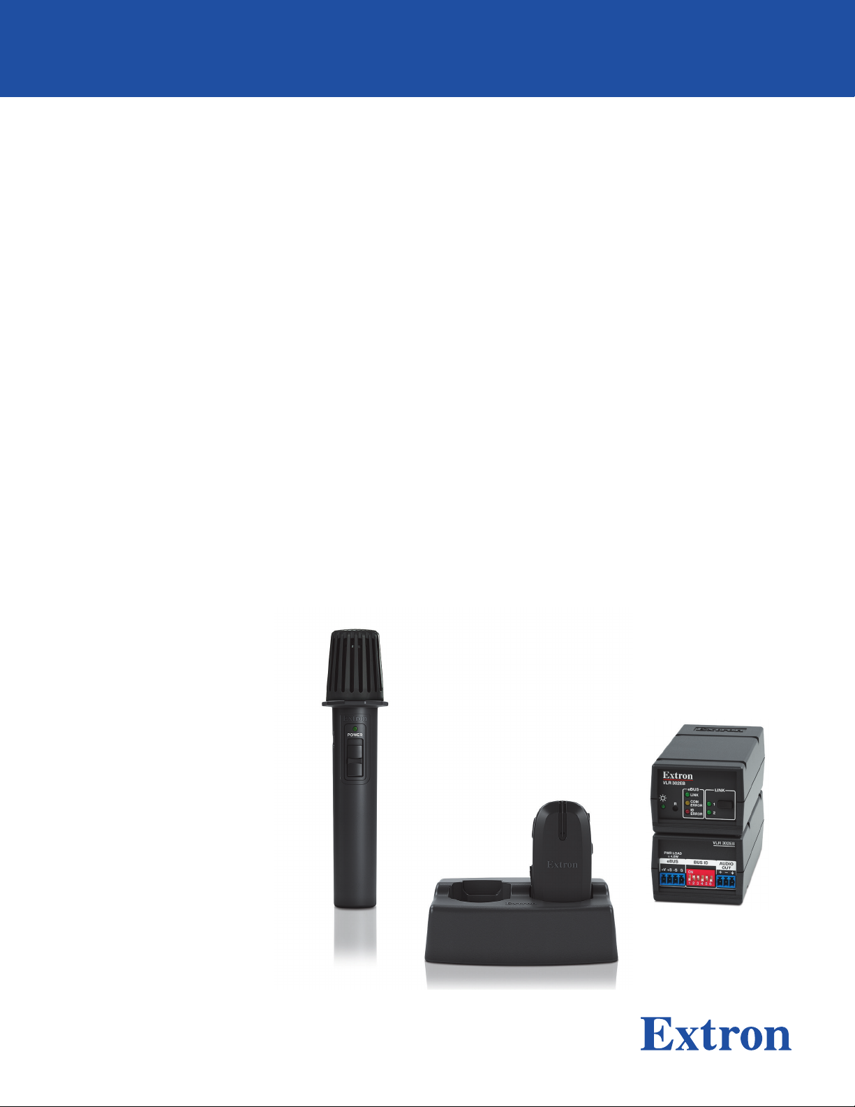
VoiceLift Pro Microphone EB Kits
User Guide
VoiceLift
68-3268-01 Rev. A
05 20
Page 2
Safety Instructions
Safety Instructions • English
WARNING: This symbol, , when used on the product, is intended to
alert the user of the presence of uninsulated dangerous voltage within the
product’s enclosure that may present a risk of electric shock.
ATTENTION: This symbol, , when used on the product, is intended
to alert the user of important operating and maintenance (servicing)
instructions in the literature provided with the equipment.
For information on safety guidelines, regulatory compliances, EMI/EMF
compatibility, accessibility, and related topics, see the Extron Safety and
Regulatory Compliance Guide, part number 68-290-01, on the Extron
website, www.extron.com.
Sicherheitsanweisungen • Deutsch
WARNUNG: Dieses Symbol auf dem Produkt soll den Benutzer darauf
aufmerksam machen, dass im Inneren des Gehäuses dieses Produktes
gefährliche Spannungen herrschen, die nicht isoliert sind und die einen
elektrischen Schlag verursachen können.
VORSICHT: Dieses Symbol auf dem Produkt soll dem Benutzer in
der im Lieferumfang enthaltenen Dokumentation besonders wichtige
Hinweise zur Bedienung und Wartung (Instandhaltung) geben.
Weitere Informationen über die Sicherheitsrichtlinien, Produkthandhabung,
EMI/EMF-Kompatibilität, Zugänglichkeit und verwandte Themen finden Sie in
den Extron-Richtlinien für Sicherheit und Handhabung (Artikelnummer
68-290-01) auf der Extron-Website, www.extron.com.
Instrucciones de seguridad • Español
ADVERTENCIA: Este símbolo, , cuando se utiliza en el producto,
avisa al usuario de la presencia de voltaje peligroso sin aislar dentro del
producto, lo que puede representar un riesgo de descarga eléctrica.
ATENCIÓN: Este símbolo, , cuando se utiliza en el producto, avisa
al usuario de la presencia de importantes instrucciones de uso y
mantenimiento recogidas en la documentación proporcionada con el
equipo.
Para obtener información sobre directrices de seguridad, cumplimiento
de normativas, compatibilidad electromagnética, accesibilidad y temas
relacionados, consulte la Guía de cumplimiento de normativas y seguridad
de Extron, referencia 68-290-01, en el sitio Web de Extron, www.extron.com.
Instructions de sécurité • Français
AVERTISSEMENT : Ce pictogramme, , lorsqu’il est utilisé sur le
produit, signale à l’utilisateur la présence à l’intérieur du boîtier du
produit d’une tension électrique dangereuse susceptible de provoquer
un choc électrique.
ATTENTION : Ce pictogramme, , lorsqu’il est utilisé sur le produit,
signale à l’utilisateur des instructions d’utilisation ou de maintenance
importantes qui se trouvent dans la documentation fournie avec le
matériel.
Pour en savoir plus sur les règles de sécurité, la conformité à la
réglementation, la compatibilité EMI/EMF, l’accessibilité, et autres sujets
connexes, lisez les informations de sécurité et de conformité Extron, réf.
68-290-01, sur le site Extron, www.extron.com.
Istruzioni di sicurezza • Italiano
AVVERTENZA: Il simbolo, , se usato sul prodotto, serve ad
avvertire l’utente della presenza di tensione non isolata pericolosa
all’interno del contenitore del prodotto che può costituire un rischio di
scosse elettriche.
ATTENTZIONE: Il simbolo, , se usato sul prodotto, serve ad avvertire
l’utente della presenza di importanti istruzioni di funzionamento e
manutenzione nella documentazione fornita con l’apparecchio.
Per informazioni su parametri di sicurezza, conformità alle normative,
compatibilità EMI/EMF, accessibilità e argomenti simili, fare riferimento
alla Guida alla conformità normativa e di sicurezza di Extron, cod. articolo
68-290-01, sul sito web di Extron, www.extron.com.
Instrukcje bezpieczeństwa • Polska
OSTRZEŻENIE: Ten symbol, , gdy używany na produkt, ma na celu
poinformować użytkownika o obecności izolowanego i niebezpiecznego
napięcia wewnątrz obudowy produktu, który może stanowić zagrożenie
porażenia prądem elektrycznym.
UWAGI: Ten symbol, , gdy używany na produkt, jest przeznaczony do
ostrzegania użytkownika ważne operacyjne oraz instrukcje konserwacji
(obsługi) w literaturze, wyposażone w sprzęt.
Informacji na temat wytycznych w sprawie bezpieczeństwa, regulacji
wzajemnej zgodności, zgodność EMI/EMF, dostępności i Tematy pokrewne,
zobacz Extron bezpieczeństwa i regulacyjnego zgodności przewodnik, część
numer 68-290-01, na stronie internetowej Extron, www.extron.com.
Инструкция по технике безопасности • Русский
ПРЕДУПРЕЖДЕНИЕ: Данный символ, , если указан на продукте,
предупреждает пользователя о наличии неизолированного опасного
напряжения внутри корпуса продукта, которое может привести к поражению
электрическим током.
ВНИМАНИЕ: Данный символ, , если указан на продукте,
предупреждает пользователя о наличии важных инструкций
по эксплуатации и обслуживанию в руководстве,
прилагаемом к данному оборудованию.
Для получения информации о правилах техники безопасности,
соблюдении нормативных требований, электромагнитной
совместимости (ЭМП/ЭДС), возможности доступа и других
вопросах см. руководство по безопасности и соблюдению
нормативных требований Extron на сайте Extron: ,
www.extron.com, номер по каталогу - 68-290-01.
安全说明 • 简体中文
警告: 产品上的这个标志意在警告用户该产品机壳内有暴露的危险 电压,
有触电危险。
注意: 产品上的这个标志意在提示用户设备随附的用户手册中有
重要的操作和维护(维修)说明。
关于我们产品的安全指南、遵循的规范、EMI/EMF 的兼容性、无障碍
使用的特性等相关内容,敬请访问 Extron 网站 , www.extron.com,参见
Extron 安全规范指南,产品编号 68-290-01。
Page 3
安全記事 • 繁體中文
警告: 若產品上使用此符 號,是為了提醒使用者,產品機殼內存在著
可能會導致觸電之風險的未絕緣危險電壓。
注意 若產品上使用此符號,是為了提醒使用者,設備隨附的用戶手冊中有
重 要 的 操 作 和 維 護( 維 修 )説 明 。
有關安全性指導方針、法規遵守、EMI/EMF 相容性、存取範圍和相關主題的詳細資
訊,請瀏覽 Extron 網站:www.extron.com,然後參閱《Extron 安全性與法規
遵守手冊》,準則編號 68-290-01。
安全上のご注意 • 日本語
警告: この 記号 が製品上に表示されている場合は、筐体内に絶縁されて
いない高電圧が流れ、感電の危険があることを示しています。
注意:この記号 が製品上に表示されている場合は、本機の取扱説明書に
記載されている重要な操作と保守( 整備)の 指示についてユーザーの注 意
を喚起するものです。
安全上のご注意、法規厳守、EMI/EMF適合性、その他の関連項目に
つ い て は 、エ ク ストロ ン の ウェブ サ イト www.extron.com よ り 『 Extron Safety
and Regulatory Compliance Guide』 ( P/N 68-290-01) をご覧ください。
안전 지침 • 한국어
경고: 이 기호 가 제품에 사용될 경우, 제품의 인클로저 내에 있는
접지되지 않은 위험한 전류로 인해 사용자가 감전될 위험이 있음을
경고합니다.
주의: 이 기호 가 제품에 사용될 경우, 장비와 함께 제공된 책자에 나와
있는 주요 운영 및 유지보수(정비) 지침을 경고합니다.
안전 가이드라인, 규제 준수, EMI/EMF 호환성, 접근성, 그리고 관련 항목에
대한 자세한 내용은 Extron 웹 사이트(www.extron.com)의 Extron 안전 및
규제 준수 안내서, 68-290-01 조항을 참조하십시오.
Copyright
© 2020 Extron Electronics. All rights reserved. www.extron.com
Trademarks
All trademarks mentioned in this guide are the properties of their respective owners.
The following registered trademarks (®), registered service marks (SM), and trademarks (TM) are the property of RGBSystems, Inc. or
ExtronElectronics (see the current list of trademarks on the Terms of Use page at www.extron.com):
Registered Trademarks (
®
)
Extron, Cable Cubby, ControlScript, CrossPoint, DTP, eBUS, EDID Manager, EDID Minder, Flat Field, FlexOS, Glitch Free. Global
Configurator, GlobalScripter, GlobalViewer, Hideaway, HyperLane, IPIntercom, IPLink, KeyMinder, LinkLicense, LockIt, MediaLink,
MediaPort, NetPA, PlenumVault, PoleVault, PowerCage, PURE3, Quantum, ShareLink, Show Me, SoundField, SpeedMount, SpeedSwitch,
StudioStation, SystemINTEGRATOR, TeamWork, TouchLink, V-Lock, VideoLounge, VN-Matrix, VoiceLift, WallVault, WindoWall, XPA, XTP,
XTPSystems, and ZipClip
Registered Service Mark
(SM)
: S3 Service Support Solutions
Trademarks (™
)
AAP, AFL (Accu-RATEFrameLock), ADSP(Advanced Digital Sync Processing), Auto-Image, AVEdge, CableCover, CDRS(ClassD
Ripple Suppression), Codec Connect, DDSP(Digital Display Sync Processing), DMI (DynamicMotionInterpolation), DriverConfigurator,
DSPConfigurator, DSVP(Digital Sync Validation Processing), eLink, EQIP, Everlast, FastBite, Flex55, FOX, FOXBOX, IP Intercom HelpDesk,
MAAP, MicroDigital, Opti-Torque, PendantConnect, ProDSP, QS-FPC(QuickSwitch Front Panel Controller), RoomAgent, Scope-Trigger,
SIS, SimpleInstructionSet, Skew-Free, SpeedNav, Triple-Action Switching, True4K, True8K, Vector™ 4K, WebShare, XTRA, and ZipCaddy
Page 4

FCC Compliance Statement
NOTE: For more information on safety guidelines, regulatory compliances,
EMI/EMF compatibility, accessibility, and related topics, see the Extron Safety and
Regulatory Compliance Guide on the Extron website.
This device complies with Part 15 of the FCC Rules for portable devices only.
Operation is subject to the following two conditions: (1) This device may not cause
harmful interference, and (2) This device must accept any interference received, including
interference that may cause undesired operation of the device.
Changes or modifications to the equipment not expressly approved by Extron Electronics
could void the user’s authority to operate the equipment.
NOTE: This equipment has been tested and found to comply with the limits for
a ClassB digital device, pursuant to Part 15 of the FCC Rules. These limits are
designed to provide reasonable protection against harmful interference in a residential
installation.
This equipment generates, uses and can radiate radio frequency energy and, if not installed
and used in accordance with the instructions, may cause harmful interference to radio
communications. However, there is no guarantee that interference will not occur in a
particular installation.
If this equipment does cause harmful interference to radio or television reception, which can
be determined by turning the equipment off and on, the user is encouraged to try to correct
the interference by one or more of the following measures:
• Reorient or relocate the receiving antenna
• Increase the separation between the equipment and receiver
• Connect the equipment into an outlet on a circuit different from that to which the
receiver is connected.
• Consult the dealer or an experienced radio/TV technician for help.
The VoiceLift Pro System has been tested/evaluated and found to comply with the FCC
radiated exposure limits and meets the FCC radio frequency (RF) Exposure Guidelines.
The Receiver unit must be installed and operated keeping it at least 20cm away from the
person’s body. The system must not be co-located or operating in conjunction with any
other antenna or transmitter.
Page 5

Canada Compliance Statement
This device complies with Industry Canada license exempt RSS standard(s). Operation is
subject to the following two conditions: (1) this device may not cause interference, and (2)
this device must accept any interference, including interference that may cause undesired
operation of the device.
Le présent appareil est conforme aux CNR d’Industrie Canada applicables aux appareils
radio exempts de licence. L’exploitation est autorisée aux deux conditions suivantes : (1)
l’appareil ne doit pas produire de brouillage, et (2) l’utilisateur de l’appareil doit accepter tout
brouillage radioélectrique subi, même si le brouillage est susceptible d’en compromettre le
fonctionnement.
CAN ICES-3 (B)/NMB-3(B)
Le système de radiofréquence VoiceLift Pro a été testé et évalué, a été jugé en conformité
avec les limites d’exposition aux radiofréquences CNR-102, et respecte les lignes directrices
relatives à l’exposition aux radiofréquences de la FCC. Le récepteur doit être installé et
fonctionner en conservant une distance minimale de 20 cm entre l’appareil et le corps
humain. Le système ne doit pas être placé à proximité ou fonctionner en association avec
une autre antenne ou un autre émetteur.
Page 6
Conventions Used in this Guide
Notifications
The following notifications are used in this guide:
CAUTION: Risk of minor personal injury.
ATTENTION : Risque de blessuremineure.
ATTENTION: Attention indicates a situation that may damage or destroy the product or
associated equipment.
NOTE: A note draws attention to important information.
Software Commands
Commands are written in the fonts shown here:
^AR Merge Scene,,Op1 scene 1,1 ^B 51 ^W^C
[01] R 0004 00300 00400 00800 00600 [02] 35 [17] [03]
E X! *X1&* X2)* X2#* X2! CE}
NOTE: For commands and examples of computer or device responses
mentioned in this guide, the character “0” is used for the number zero and “O”
is the capital letter “o.”
Specifications Availability
Product specifications are available on the Extron website, www.extron.com.
Page 7

Contents
Introduction............................................................ 1
About this Guide ................................................. 1
About the VoiceLift Pro Microphone EB Kits
(VLME Kits) ........................................................ 2
VoiceLift Pro Microphone Features...................... 3
Application Diagram ........................................... 4
VLME Kit Installation and Operation ............... 5
VoiceLift Pro Microphone EB Kit Overview .......... 5
VLP 302 Microphone Features ........................ 6
VLH 302 Microphone Features ....................... 8
Installing the VLC 302 Charger and
Charging the Microphones ................................ 9
Installing the VLR 302EB Receiver .................... 11
Setting eBUS IDs .......................................... 12
Setting up the Microphones .............................. 15
VLP 302 Pendant Microphone ...................... 15
VLH 302 Handheld Microphone .................... 16
Pairing the Microphones with the
VLR 302EB Receiver ....................................... 16
Clear previously paired microphones from
the VLR receiver .......................................... 16
Pair New Microphones.................................. 16
Tips for Using the Microphones ........................ 18
Saving the Microphone Volume Level ............... 18
Reference Information ...................................... 19
Mounting the VLR 302EB Receiver ................... 19
Rack Mounting ............................................. 19
ZipClip Mounting .......................................... 20
Firmware ...................................................... 21
Resetting the VLR 302EB ................................. 22
Reset Mode 1 ............................................... 22
Reset Mode 2 ............................................... 22
Reset Mode 3 ............................................... 22
Extron Warranty .................................................. 23
VoiceLift Pro Microphone EB Kits User Guide • Contents xii
Page 8

VoiceLift Pro Microphone EB Kits User Guide • Contents xiii
Page 9

Introduction
This section covers the following topics:
• About this Guide
• About the VoiceLift Pro Microphone EB Kits
• VoiceLift Pro Microphone Features
• Application Diagram
About this Guide
This guide describes the components, installation, and operation of Extron VoiceLift Pro
Microphone EB Kits, which include the pendant or handheld microphones, the receiver,
and the charging station (see About the VoiceLift Pro Microphone EB Kits on the next
page for details).
CAUTION: Risk of explosion. Do not replace the battery with an incorrect type. Dispose
of used batteries according to the instructions.
ATTENTION : Risque d’explosion. Ne pas remplacer la pile par le mauvais type de pile.
Débarrassez-vous des piles usagées selon le mode d’emploi.
ATTENTION:
• Installation and service must be performed by authorized personnel only.
• L’installation et l’entretien doivent être effectués par le personnel autorisé
uniquement.
• UL listed electrical boxes are recommended.
• Des boîtiers électriques approuvés UL sont recommandés.
The following terms are used in this guide:
• “Microphone” refers to the VLP 302 or VLH 302.
• “Receiver” refers to the VLR 302EB receiver. The receiver can be mounted into Extron
enclosures or can be rack mounted. One receiver can host up to two microphones.
• “Charging station” refers to the VLC 302 charger for dual microphones (VLP or VLH).
VoiceLift Pro Microphone EB Kits User Guide • Introduction 1
Page 10
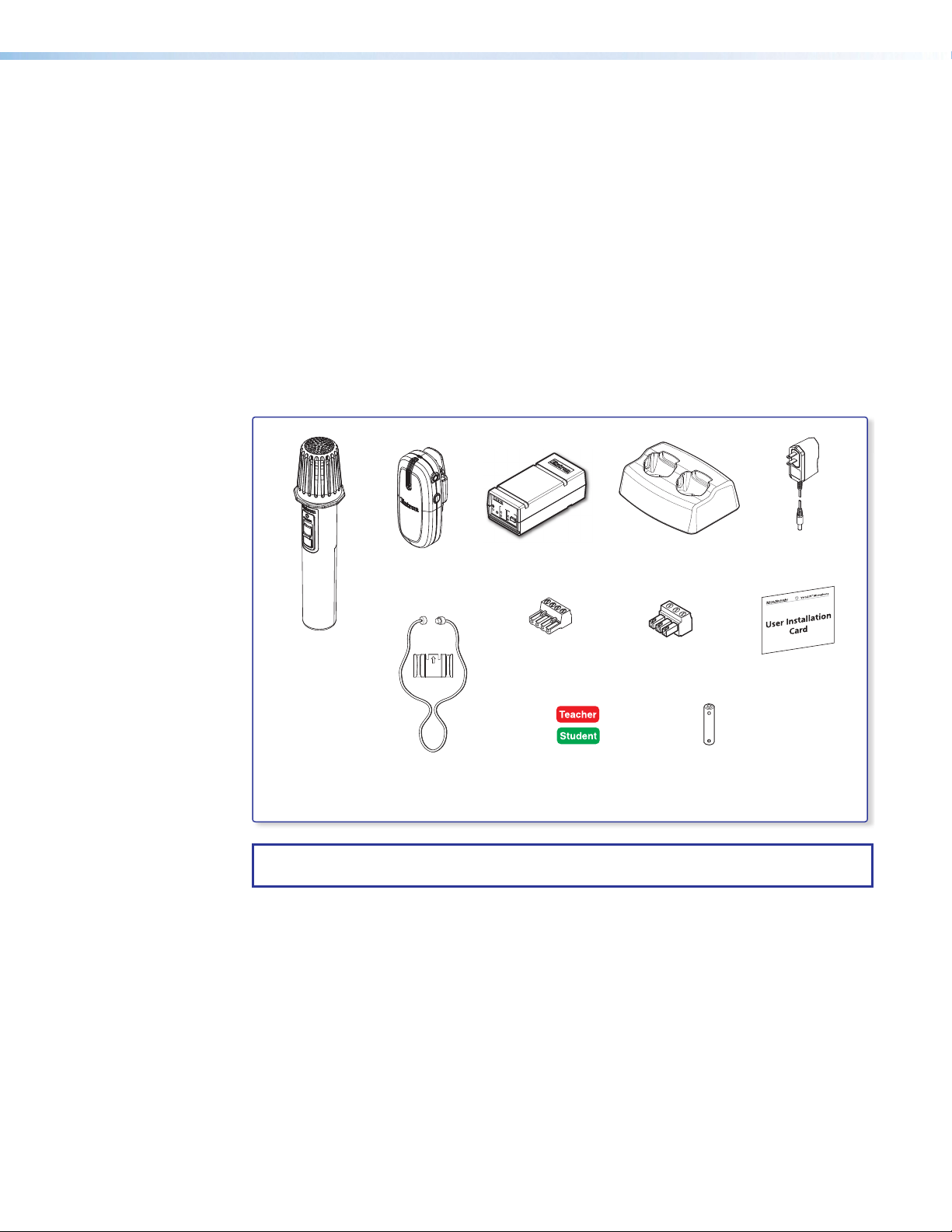
About the VoiceLift Pro Microphone EB Kits (VLME Kits)
A VoiceLift Pro Microphone EB Kit is a voice amplification system that enables a teacher or
presenter to be clearly heard at a comfortable level throughout the entire room. The system
is designed to be used in conjunction with an IPCP Pro control processor.
There are three types of VoiceLift VLME kits available:
• VLME 3001 includes:
One VLP 302 pendant microphone, a VLR 302EB receiver, and a VLC 302 charging
station.
• VLME 3002 includes:
Two VLP 302 pendant microphones, a VLR 302EB receiver, and a VLC 302 charging
station.
• VLME 3002H includes:
One VLP 302 pendant microphone, one VLH 302 handheld microphone, a VLR 302EB
receiver, and a VLC 302 charging station.
VLR 302EB
eBUS
LINK
R
LINK
COM
ERROR
ID
ERROR
1
2
Charger
Power Supply
VLP 302 Pendant
VLR 302EB
RF Receiver
VLC 302
Charging Station
Microphone
VLH 302 Handheld
Microphone
(1) 4-pole captive
screw connector
(1) 3-pole captive
screw connector
VoiceLift User
Installation Card
Lanyard and
Lanyard Lock
(for VLP 302)
Microphone
Labels
AA Rechargeable
Battery
NOTE: If any items in the VLME kit are damaged or missing, contact Extron Technical
Support.
VoiceLift Pro Microphone EB Kits User Guide • Introduction 2
Page 11

VoiceLift Pro Microphone Features
• Lightweight microphones — The microphones are made of lightweight and
impact-resistant polycarbonate material. The VLP 302 pendant microphone can be
worn comfortably around the neck or clipped to clothing. The VLH 302 can be used for
multiple presenters and as a student pass-around microphone.
• Built-in DSP — The receiver has an integrated digital signal processor (DSP) that
maximizes sound quality and intelligibility.
• Two microphones per receiver — An installed VoiceLift System supports up to two
microphones and can be used by instructors and students.
• Power switch — The VLP 302 pendant microphone has an easily accessible switch
on the side to mute the sound and power the microphone on and off. The VLH has a
sliding switch which toggles the microphone on and off.
• Volume buttons — Volume buttons on the VLP 302 are conveniently located, enabling
the presenter to easily raise and lower the volume during use. Volume buttons on the
VLH 302 are hidden within the battery compartment.
• Auxiliary microphone input (VLP 302) allows use of an optional lavalier or headset
microphone.
• Auxiliary audio input (VLH 302) for an external audio source, such as an MP3 player.
• Battery power — The VLP 302 and VLH 302 microphones are powered by a single
NiMh or alkaline AA battery. NiMh batteries can be recharged in the VLC 302 charging
station.
• VLC 302 charging station — Holds and recharges up to two microphones.
• Receiver mounting options — The VLR 302EB receiver is compact and can be
mounted within Extron enclosures or can be rack mounted.
VoiceLift Pro Microphone EB Kits User Guide • Introduction 3
Page 12

Application Diagram
The application diagram below shows a typical installation incorporating an IPCP Pro with a
VoiceLift Pro microphone system.
Figure 1. Typical Room Installation
VoiceLift Pro Microphone EB Kits User Guide • Introduction 4
Page 13

VLME Kit Installation
A
and Operation
This section covers the following topics:
• VoiceLift Pro Microphone EB Kit Overview
• Installing the VLC 302 Charger and Charging the Microphones
• Installing the VLR 302EB Receiver
• Setting up the Microphones
• Pairing the Microphones with the VLR 302EB
• Tips for Using the Microphones
• Saving the Microphone Volume Level
VoiceLift Pro Microphone EB Kit Overview
The figure below shows the path of the audio signal through the VoiceLift System.
VLP or VLH Microphone
MPA 152 PLUS
POWER
12V
0.7A MAX
VLR 302EB Receiver
B
VLR 302EB
PWR LOAD
0.3A MAX
eBUS
BUS ID
+V +S -S G
ON
1 2
3 4
5 6
INPUTS
L
R
AUDIO
OUT
/
Ω
CLASS 2
WIRING
L
Audio Amplifier
C
R
VCG
10V 50mA
OUTPUTREMOTE
4Ω8
L
R
Figure 2. VoiceLift System Audio Signal Path
VLP or VLH Microphone — The VLP 302 and VLH 302 microphone transmits the
A
voice audio signal to the VLR 302EB receiver.
VLR 302EB Receiver — The VLR 302EB receives the signal from the microphone, and
B
outputs a balanced mono line level signal (-10 dBV) to a connected audio device.
MPA 152 Plus — The MPA 152 Plus receives and amplifies the incoming balanced
C
mono audio from the VLR 302EB.
VoiceLift Pro Microphone EB Kits User Guide • VLME Kit Installation and Operation 5
Page 14

VLP 302 Microphone Features
B
G
I
J
A
c
E
D
H
F
Figure 3. VLP 302 Microphone Features
— Status LED (tri-color)
A
— Microphone acoustic ports
B
— Auxiliary microphone input (3.5 mm
C
mono female input jack)
— Function button
D
— Spring Clip
E
Status LED — This LED indicates the microphone power, volume, and charging status as
A
follows:
LED indicators when the microphone is powered on and in use:
— Microphone identification
F
label recess
— Power/mute button
G
— Volume button (increase)
H
— Volume button (decrease)
I
— Charging contacts
J
LED Color Indication
LED off Microphone is OFF or battery not installed.
Green – steady Microphone is ON and active.
Green – slow blinking Microphone is muted.
Green – single blink Volume adjusted (increased or decreased).
Green – double blink Volume adjusted to maximum level.
Red – slow blinking Low battery (30 minutes or less of talk time left); recharge battery.
Red – steady Battery life depleted; recharge battery.
Red – steady (5 seconds)
Amber (flashes for 5 seconds) Function button activated.
Red and green – alternate
blinking
LED indicators when the microphone is charging:
LED Color Indication
Red – steady Battery charging
Green – steady Battery fully charged
Red and green – alternate
blinking
Instant Alert activated. Volume Up and Down buttons
pressed and held simultaneously for 3 seconds (Instant Alert state
changed to "True").
LED and state revert back to "False" after 5 seconds.
Function button was pressed and held for 2 seconds. Function
state is toggled to opposite state (true/false).
Microphone is in pairing mode and attempting to link with receiver.
Incompatible, faulty or failed battery detected. Replace battery.
VoiceLift Pro Microphone EB Kits User Guide • VLME Kit Installation and Operation 6
Page 15

Microphone acoustic audio input ports — The microphone receives voice audio
B
through these two acoustical ports. Do not block these ports while the microphone is in
use.
Auxiliary microphone input (Audio In) — Connect an auxiliary lavalier microphone
C
into this 3.5 mm mono auxiliary mic input jack. When an external lavalier microphone is
connected, the built in microphone elements in the VLP 302 are disabled.
Function button — When this button is pressed and held for two seconds, the
D
microphone signals the receiver to toggle Relay 2 to its opposite state.
NOTE: The VLP 302 microphone status LED flashes amber for 5 seconds,
indicating that the relay has been toggled.
The Function button is also used in conjunction with the Power button to initiate Link
(pairing) mode (see Setting up the Microphones on page 15).
Spring clip — Use this clip to attach the VLP 302 to clothing or to a lanyard (included)
E
(see step 4 on page 15 for instructions).
The lanyard lock is used to retain proper position of the microphone when clipped to
the lanyard. The breakaway clasps help to release the lanyard from around the neck if
it is pulled tightly. Place this clasp at the back of your neck when wearing the pendant
microphone.
Microphone identification label recess — Place the appropriate provided sticker in
F
this space to identify the microphone user (see step 3 on page 15).
Power and mute button (Off/Mute/On) — Press and hold the Power button (for
G
three seconds) to power the microphone on or off.
With the device on, press and release this button momentarily to mute or unmute the
microphone.
Volume buttons — Raise or lower the microphone volume.
HI
Pressing and holding both of these buttons simultaneously for 3 seconds sends a signal
to the receiver to initiate Instant Alert state.
Charging contacts — Used when charging the microphone in the VLP 302 charging
J
station. A full charge can take up to 5 hours.
VoiceLift Pro Microphone EB Kits User Guide • VLME Kit Installation and Operation 7
Page 16

VLH 302 Microphone Features
A
B
C
D
Front Side
Figure 4. VLH 302 Microphone Features
Power Switch — Slide up to power on and down to power off.
A
Power Status LED — Dual color LED (green and red) indicates power or Link status.
B
LED indicators when the microphone is powered on and in use:
LED Color Indication
LED off Microphone is OFF or battery is not installed.
Green – steady Microphone is ON.
Green – single blink Volume adjusted (increased or decreased).
Green – double blink Volume adjusted to maximum level.
Red – slow blinking Low battery (30 minutes or less of talk time left);
recharge battery.
Red – steady Battery life depleted; recharge battery.
Red and green – alternating
blink
Microphone in pairing mode and attempting to link with
receiver.
+
E
F
Rear
LED indicators when the microphone is charging:
LED Color Indication
Red – steady Battery charging
Green – steady Battery fully charged
Red and green – alternating
blink
Auxiliary Stereo Audio Input — 3.5 mm stereo input accepts line level audio signals,
C
but does not support external lavalier/lapel microphones. When an active aux input
device is connected, the built in microphone is disabled. The audio from the auxiliary
audio source is summed to mono and transmitted to the receiver.
Link button — This button is used to enable pairing mode.
D
Volume buttons — Increase ( ) or decrease ( ) the microphone volume.
EF
VoiceLift Pro Microphone EB Kits User Guide • VLME Kit Installation and Operation 8
Incompatible, faulty, or failed battery detected.
Check and replace battery.
Page 17

Installing the VLC 302 Charger and Charging the Microphones
(Cover Removed)
22
The VLC 302 charges the microphone battery. It is powered by an external wall power
supply (provided). The microphone battery requires up to 5 hours to charge fully. It is safe
to charge for extended periods, but Extron recommends storing the microphone out of the
charger with the battery removed.
NOTES:
• The charging station is to be used with NiMH rechargeable batteries only.
• Fully charge the supplied batteries before first use.
Follow these steps to connect the charger and
charge the microphones.
1. Connect the 5 VDC, 2.6 A wall charger to
a 110-130 VAC (U.S.) or a 100-240 VAC
(international), 50-60 Hz power source
(see 1 at right).
2. Connect the USB mini plug end of the adapter
to the USB mini jack located on the back of the
VLC 302 (2).
11
3. To install the battery, remove the microphone battery
cover as follows:
• VLP 302: Unscrew the two rear panel screws
located on either side of the rear clip.
• VLH 302: Slide the battery cover downward
until it stops, then lift the cover up and off the
microphone.
Insert the battery, aligning the + and – poles as
indicated inside the compartment.
_
BATTERY
+
VLP 302
(Cover Removed)
BATTERY
+
VLH 302
CAUTION: Use only NiMH rechargeable batteries provided by Extron when charging
the microphone. Use of any rechargeable battery other than the type provided by
Extron may cause explosion, chemical leakage, and injury.
ATTENTION : Utilisez uniquement les piles rechargeables de type NiMH fournies par
Extron, lorsque vous rechargez le microphone. L’utilisation d’une pile rechargeable
différente du type fourni par Extron peut présenter un risque d’explosion, de fuite de
substances chimiques, ou de blessure.
ATTENTION: Be sure to replace the battery with the correct type and to dispose of
used batteries appropriately.
ATTENTION: Assurez vous de remplacer les piles par le bon modèle et de jeter les
piles usagées de façon appropriée.
VoiceLift Pro Microphone EB Kits User Guide • VLME Kit Installation and Operation 9
Page 18

4. Insert the microphone into one of the charger slots (4).
11
22
44
The microphone LED turns red when the microphone is
charging.
LED Color Indication
Red – steady Battery charging
Green – steady Battery fully charged
Red and green – alternate
blinking
NOTES:
• The microphone battery requires up to 5 hours to charge fully. It is safe to
charge for extended periods, but Extron recommends storing the microphone
out of the charger with the battery removed.
• Make sure that the microphones are fully seated in the charging station to
ensure proper charging. The microphone will flash amber for 3 seconds when
initially docked into the charger.
ATTENTION:
• Do not charge alkaline batteries.
• Ne rechargez pas les piles alcalines.
• Use only Extron provided LPS type power supply charger for charging.
• Veuillez utiliser uniquement le bloc d’alimentation de type LPS fourni par Extron
pour la recharge.
Incompatible or failed
battery detected. Check
and replace battery.
LED
VoiceLift Pro Microphone EB Kits User Guide • VLME Kit Installation and Operation 10
Page 19

Installing the VLR 302EB Receiver
AB
C
+
Drain Wires (2)
G
S
+S
+V
Sleev
The VLR 302EB receiver outputs audio signals from the microphones as one balanced mono
line level signal to a connected audio device. In dual microphone systems, the signals from the
two microphones are mixed at the receiver and then output to the connected device.
Connect the VLR 302EB as shown below. For mounting options and instructions, see
Mounting the VLR 302EB Receiver on page 19.
VLR 302EB
PWR LOAD
= 4.0W
eBUS
+V +S -S G
Figure 5. VLR 302EB Rear Panel
eBUS connector — Connect an Extron IPCP Pro control processor to this four-pole
A
captive screw connector.
NOTES:
BUS ID
ON
1 2
AUDIO
OUT
3 4
5 6
• The VLR 302EB requires an eBUS connection to an Extron IPCP Pro processor
for power and communication. If not connected to an IPCP Pro processor, the
VLR 302EB will not output audio.
• See the ATTENTION on the next page.
Extron STP20-2/1000 or STP20-2P/1000 cable is recommended for eBUS connections.
Connect a 4-pole captive screw connector to each end of the cable, wiring both ends as
shown below.
12 VDC
+ Signal
-
Signal
Ground
DIP switches — Use these DIP switches to assign an eBUS ID to the devices connected
B
Red
Green
White
Black
-
to the IP Link control processor. Each device connected to the control processor must
have a unique eBUS ID (see Setting eBUS IDs on the next page).
Audio output — Connect a balanced or unbalanced audio device to this 3-pole mono
C
captive screw connector. Wire the connector as shown below:
Tip
Ring
e
Balanced Output
3-pole Mono Audio OUTPUT Wiring
Tip
NO Ground Here
Sleeve
Unbalanced Output
ATTENTION:
• For unbalanced audio, connect the sleeves to the ground contact. DO NOT
connect the sleeves to the negative (-) contacts.
• Pour l’audio asymétrique, connectez les manchons au contact au sol. Ne PAS
connecter les manchons aux contacts négatifs (–).
VoiceLift Pro Microphone EB Kits User Guide • VLME Kit Installation and Operation 11
Page 20

Setting eBUS IDs
Up to eight eBUS devices can be connected to one control processor. Each device
connected to the same IPCP Pro control processor must have a unique BUS ID, which is set
using the BUS ID DIP switches (see B on the previous page).
NOTE: If two or more modules have the same eBUS ID, address conflicts may cause one
or more of the devices to not be recognized by the IPCPPro control processor.
Various combinations of the six DIP switches (being set to On or Off) provide 64 eBUS IDs:
• 0 is reserved for the controller
• 1 through 63 is the configurable eBUS ID range.
On
4
=16
2
Dip Switch
3
4
On
Off
2
3
2
2
=4
=8
2
On
1
5
=2
6
Off
0
2
=1
BUS ID
ON
1 2
3 4
5 6
Position
Decimal
1
Off
5
2
=32
2
0 + 16 + 8 + 0 + 2 + 0 = 26
NOTES:
• Connect up to eight eBUS devices for each IPCP Pro control processor, while taking
into consideration the available power from the IPCP Pro processor. The VLR 302EB
requires 4W of power.
• Wire the connectors in the same way at both ends.
• Do not exceed a total of 1000 feet (305 meters) of cable for connections between the
IPCP Pro and all the eBUS devices.
• Do NOT power an eBUS device from more than one power source. Power is provided
by the IPCP Pro. If additional power is required, use a PS 1220EB power supply and
distribution hub, or an Extron 12 VDC power supply. If more than one power source
is used in a system, make sure that the devices powered by the first source are
isolated from the devices powered by the second source by disconnecting the +V pin
appropriately (see figure 6 on the following page).
• See the eBUS Technology Reference Guide available at www.extron.com for details.
ATTENTION:
• Always use a power supply supplied or specified by Extron. Use of an unauthorized
power supply voids all regulatory compliance certification and may cause damage
to the supply and the unit.
• Utilisez toujours une source d’alimentation fournie par Extron. L’utilisation d’une
source d’alimentation non autorisée annule toute conformité réglementaire et peut
endommager la source d’alimentation ainsi que l’unité.
• If not provided with a power supply, this product is intended to be supplied by a UL
Listed power source marked “Class 2” or “LPS”, rated output 5Vdc min. 0.5A. For
VLR 302CS, rated 12Vdc min. 0.5A.
• Si ce produit n’est pas fourni avec une source d’alimentation, il doit être alimenté
par une source d’alimentation certifiée UL de classe 2 ou LPS, avec une tension
nominale 5 Vcc, 0,5 A minimum. Pour un VLR 302CS, 12 Vcc, 0,5 A minimum.
• Unless otherwise stated, the AC/DC adapters are not suitable for use in air handling
spaces or in wall cavities.
• Sauf mention contraire, les adaptateurs AC/DC ne sont pas appropriés pour une
utilisation dans les espaces d’aération ou dans les cavités murales.
VoiceLift Pro Microphone EB Kits User Guide • VLME Kit Installation and Operation 12
Page 21

ATTENTION:
C
G
G
S
CTS
3
G
G
C
S
G
MAC: 00-05-A6
XX
S/
#
X
X
EBP 100
eBUS 24 WATTS MAX
100-240V 50-60Hz
0.6A MAX
• The installation must always be in accordance with the applicable provisions of
National Electrical Code ANSI/NFPA70, article725 and the Canadian Electrical
Code part1, section16. The power supply shall not be permanently fixed to
building structure or similar structure.
• Cette installation doit toujours être en accord avec les mesures qui s’applique au
National Electrical Code ANSI/NFPA70, article725, et au Canadian Electrical Code,
partie1, section16. La source d’alimentation ne devra pas être fixée de façon
permanente à une structure de bâtiment ou à une structure similaire.
ON
1 2
BUS ID
3 4
VLR 302EB
5 6
AUDIO
OUT
BUS ID
M
B
S
12
3456
B
S
L
+V +S -S G+V +S -S G
ON
eBUS
PWR LOAD = X.XW
PWR LOAD
= 4.0W
eBUS
+V +S -S G
eBUS Connections
• Connect up to ve (5) eBUS
endpoint devices to the PS 1220EB.
•Wire the connectors the same at both
ends.
• All ports are identical and
interchangeable.
COM 1
T
RRT
POWER
VOL
1.0A MAX
IPCP Pro
COM 2
Tx
RELAYS
DIGITAL I/O
eBUS
-S+V +S G
PWR OUT = 6W
X
IPCP PRO 250
-XX-XX-
N: ####### E#####
IR/S
LA
ATTENT ION: Do NOT c onnect the
power pin to any device that is already
powere d by the IPC P Pro control
processor or by an additional power
supply.
+ Signal
-
Signal
Ground
100-240V 50-60Hz
Power Input
(100-240 VAC,
50-60 Hz)
0.6A MAX
-S+V +S G-S+V +S G-S+V +S G
eBUS 24 WATTS MAX
-S+V +S G-S+V +S G-S+V +S G
X
Tie drain wires
to ground.
PS 1220EB
+12 VDC
+ Signal
-
Signal
Ground
3/16"
(5 mm)
Max.
Ground
-
Signal
+ Signal
+12 VDC
Figure 6. VLR 302EB Connection Diagram
VoiceLift Pro Microphone EB Kits User Guide • VLME Kit Installation and Operation 13
Page 22

C
G
PO
12V
1.0
G
Tx
R
S
CTS
3
2
4
G
G
TxR
C
S
G
M
X
S/
#
BUS ID
A
B
S
12
3456
B
S
M
ON
eBUS
L
PWR LOAD = X.XW
+V +S -S G+V +S -S G
WER
A MAX
IPCP Pro
COM 1
xRT
VOL
COM 2
x
RELAYS
DIGITAL I/O
1
eBUS
-S+V +S G
PWR OUT = 6W
PWR LOAD
+V +S -S G
= 4.0W
eBUS
IPCP PRO 250
AC: 00-05-A6-XX-XX-X
N: ####### E#####
IR/S
BUS ID
ON
1 2
3 4
VLR 302EB
5 6
AUDIO
OUT
3/16" (5 mm) Max.
Tie drain wires to ground.
Ground
-
Signal
+ Signal
Ground
-
Signal
+ Signal
+12 VDC
EBP 100
RidgedSmooth
+12 VDC input
VLR 302EB
External Power Supply
(12 VDC, 1.5 A max.)
– Return
Ground
all Devices
NOTE:
supply before connecting it to the EBP.
Check the polarity of the power
Figure 7. VLR 302EB Connection Diagram
Verify that the DIP switches on the VLR and other eBUS
devices are set to the desired address on each device and
that there are no BUS ID conflicts in the system.
VLR 302EB
R
eBUS
LINK
COM
ERROR
ID
ERROR
LINK
1
2
The eBUS status LEDs (see A at right) provide information
about power and communication status and bus ID address
conflicts.
The VLR 302EB has three LEDs:
• Off — If all three LEDs are off, the device is not receiving power.
• Green LED — Lights solidly when power and communication are both confirmed.
• Yellow LED— Lights solidly when the device is receiving power but communication
with the control processor is not confirmed.
• Red LED— Lights solidly when there is a BUS ID address conflict.
VoiceLift Pro Microphone EB Kits User Guide • VLME Kit Installation and Operation 14
Page 23

Setting up the Microphones
2
TEACHER
3
c
b
Press to
open clip
Lanyard
Lock
a
~ 6
”
Status
LED
5
6
VLP 302 Pendant Microphone
To set up the VLP 302 microphone:
1. Verify that the battery is installed and fully charged.
2. Set the microphone(s) for either "teacher" or "student" mode using the DIP switch,
accessible from beneath the battery cover (see 2 below):
• In teacher mode (default), all
microphone features are fully
functional. Set the dip switch to
the OFF (down) position to enable
“teacher” mode.
• In student mode, all buttons are
disabled except for power. Set the
dip switch to the ON (up) position to
enable “student” mode.
3. Apply the appropriate label (provided) to
identify the microphone (see 3 at right).
4. To wear as a pendant microphone:
a. Push the lanyard into the guides on
the lanyard lock (see a at right).
b. Open the microphone clip (b).
c. Slide up the lanyard lock under the
clip, then release the clip (c).
d. Place the lanyard around
your neck and adjust the
microphone position by
sliding it up so it rests
approximately
6 inches (15.2 cm)
below your chin.
5. Turn the microphone(s) on by holding the power button (5)
for three seconds. One of the LINK LEDs on the
VLR 302EB receiver will illuminate to indicate that connection
has been established.
NOTE: Each VLME kit includes microphones and a
VLR 302EB receiver that have already been
paired. If there is a need to pair a microphone,
follow the steps on the next page.
6. Speak in a normal tone of voice, adjusting the volume level
(6) as necessary.
7. When finished, return the microphone to the charging station.
VoiceLift Pro Microphone EB Kits User Guide • VLME Kit Installation and Operation 15
Page 24

VLH 302 Handheld Microphone
(Cover Removed)
A
B C
A
To set up the VLH 302 microphone:
1. Verify that the battery is installed and fully charged.
2. Turn the microphone on by sliding up the power
switch (see A at right).
NOTE: Each VLME kit includes
microphones and a VLR 302EB receiver
that have already been paired. If there is
a need to pair a microphone, follow the
steps in the next section, below.
3. Speak in a normal tone of voice, adjusting the
volume level as necessary. The volume buttons are
located under the microphone cover (see B at
right).
4. When finished, return the microphone to the charging station.
Pairing the Microphones with the VLR 302EB Receiver
Each VoiceLift kit includes microphones and a VLR 302EB receiver that have already
been paired. If needed, follow the steps below to pair microphones with a receiver.
Clear previously paired microphones from the VLR receiver
1. Ensure that the microphones are placed in the
VLC 302 charger or powered off.
2. Press and hold the Reset button (A) until the
Power LED flashes once (approx. 3 seconds),
then immediately release and momentarily press
the Reset button again (for <1 second) within 1
second.
Both LINK LEDs (B) blink to confirm pairing has
been cleared.
VLR 302EB
R
eBUS
LINK
COM
ERROR
ID
ERROR
+
B
VLH 302
LINK
1
2
Pair New Microphones
Follow these steps to pair each microphone, one at a time, to the VLR 302EB receiver.
NOTE: All paired microphones should be fully charged and turned off before pairing new
microphones.
1. Press and hold the LINK button on the VLR 302EB receiver (see C in the image above) for
4 seconds to start pairing mode. If LINK slots are available, one of the LINK LEDs (see B in
the image above) blinks to indicate that pairing mode has started.
NOTES:
• Once initiated, the VLR receiver pairing mode is enabled for 30 seconds, and
users must set the microphones to pairing mode (see step 2 on the next page)
within the allocated time. Repeat the process if the 30 second pairing window
time has been exceeded or if pairing was not successful.
• Receiver Pairing/Discovery mode can also be enabled remotely from a control
system that has been configured to control the VLR receiver.
VoiceLift Pro Microphone EB Kits User Guide • VLME Kit Installation and Operation 16
Page 25

2. Follow the steps below for your microphone model:
• VLP 302:
Ensure that the microphone is powered off.
NOTE: VLP 302 microphone must
be set to Teacher Mode (see
page 15) in order to initiate pairing
mode.
B
While powered off, press and hold the
Function and Power buttons (see
and B at right) simultaneously for
A
4 seconds until the status LED blinks
red and green, indicating pairing mode
has started.
• VLH 302:
Power the VLH 302 handheld microphone on.
Press and hold the LINK button located beneath the battery cover
(see C at right) for 4 seconds until the status LED blinks red and
green, indicating pairing mode has started.
NOTE: The receiver assigns the microphone to the first available
LINK slot. The LINK LED on the VLR receiver will illuminate solid
green when the microphone has been paired successfully.
3. Once a microphone has been paired, test the audio by speaking into the microphone, then
power the microphone off.
4. Repeat from step 1 for each microphone being paired.
5. After pairing the microphones, verify that they have been set up properly (see Setting up
the Microphones on page 15).
A
C
VoiceLift Pro Microphone EB Kits User Guide • VLME Kit Installation and Operation 17
Page 26

Tips for Using the Microphones
• Speak in a normal tone of voice. When the microphone is set up properly, voice audio is
amplified just above ambient room noise.
• Mute or turn the microphone off while having private conversations.
• Return the microphones to the charging station when not in use. Verify that the microphones
are fully seated in the VLC 302 charger to ensure batteries are charged.
• If you are experiencing intermittent audio problems, check the batteries and replace them if
necessary. NiMH and alkaline batteries are supported.
CAUTION: Do not replace the battery with an incorrect type. Use only NiMh or
alkaline batteries.
ATTENTION : Ne pas remplacer la pile par le mauvais type de pile. Utilisez
seulement des piles de type NiMh ou alkaline.
ATTENTION:
• Do not recharge alkaline batteries.
• Ne rechargez pas les piles alkalines.
• Dispose of used batteries according to the instructions provided on the battery
packaging.
• Débarrassez-vous des piles utilisées selon les instructions du fabricant.
Saving the Microphone Volume Level
Saving the microphone level allows the microphone to power on to the stored setting.
To save the microphone volume level:
1. Adjust the volume on each microphone to the desired level.
2. Manually power down each microphone:
• For the pendant microphone, press and hold the power button until the LED turns off.
• For the handheld microphone, slide power switch to off position.
3. Wait 30 seconds before turning the microphones on or placing them in the charger.
VoiceLift Pro Microphone EB Kits User Guide • VLME Kit Installation and Operation 18
Page 27

Reference
Universal Rack Shelf Kit
Information
This section provides the following reference information:
• Mounting the VLR 302EB Receiver
• Firmware
• Resetting the VLR 302EB
Mounting the VLR 302EB Receiver
Rack Mounting
The receiver includes 1/8 rack mounting holes for mounting directly to a rack shelf or
architectural enclosure that supports standard Extron mounting hole patterns.
UL Guidelines for Rack Mounting
The following Underwriters Laboratories (UL) guidelines are relevant to the safe installation of
this product in a rack:
• Elevated operating ambient temperature — If the unit is installed in a closed or
multi-unit rack assembly, the operating ambient temperature of the rack environment
may be greater than room ambient temperature. Therefore, install the equipment in an
environment compatible with the maximum ambient temperature
(TMA = +122 °F, +50°C) specified by Extron.
• Reduced air flow — Install the equipment in the rack so that safe operation and
adequate air flow is provided to the unit.
• Mechanical loading — Mount the equipment in the rack so that a hazardous
condition is not achieved due to uneven mechanical loading.
• Circuit overloading — Connect the equipment to the supply circuit and consider the
effect that circuit overloading might have on overcurrent protection and supply wiring.
Consider the equipment nameplate ratings when addressing this concern.
• Reliable earthing (grounding) — Maintain reliable grounding of rack-mounted
equipment. Pay particular attention to supply connections other than direct
connections.
Rack Mounting Options
The receiver can be mounted on optional
rack systems listed on the website (see
www.extron.com). To mount the unit
on a rack shelf, follow the instructions
provided with the shelf accessories.
VoiceLift Pro Microphone EB Kits User Guide • Reference Information 19
VLR 302EB
eBUS
LINK
R
LINK
COM
ERROR
ID
ERROR
1
2
RSU 129
Page 28

Back of the Rack Mounting Options
1
2
VLR 302EB
LINK
1
2
R
eBUS
LINK
COM
ERROR
ID
ERROR
The receiver can be mounted to the rear of a rack using an optional back of rack mounting
kit (see www.extron.com). The kit allows the product to be vertically mounted to the front or
rear rack supports and face either the front or the rear of the rack. To mount the unit, follow
the instructions provided with the kit.
ZipClip Mounting
Using the ZipClip 100 (optional)
To attach the receiver to the ZipClip 100 mounting clip:
1. Insert the bottom of the receiver down into
the clip, starting with one end.
2. Pivot the other end down and press until
the clip snaps into place.
To remove the receiver from the ZipClip:
1. Press the tab on the ZipClip.
2. Pivot the receiver and lift it out of the ZipClip.
To fasten the tie wraps for cable strain relief:
1. Attach the receiver to the ZipClip 100 mounting
clip as described previously.
2. Fasten the cables to the ZipClip base.
a. Insert tie wraps (“zip ties”) along the
notches on the side of the receiver and
through the tie wrap anchor points on the
ZipClip, then around the cord.
Tie Wrap
b. Connect and pull the tie wraps until they
See the ZipClip 100 Installation Guide (available at www.extron.com) for mounting options
are secure. Do not over tighten.
and instructions.
1
2
VLR 302EB
eBUS
LINK
R
LINK
COM
ERROR
ID
ERROR
1
2
Cable
Strain
Relief
VoiceLift Pro Microphone EB Kits User Guide • Reference Information 20
Page 29

Firmware
All eBUS devices must have firmware that is compatible with the control processor. To
ensure this, the eBUS device firmware is managed automatically by the control processor.
Updates to the configuration file or product firmware are pushed to eBUS devices via the
IPCP Pro control processor.
When the system is powered on with an eBUS device is connected to the control
processor, the processor checks the firmware version that is installed on the eBUS device
and, if necessary, updates the endpoint device firmware to a compatible version. While
an eBUS device is receiving the firmware update, the front panel LED of the IPCP control
processor flashes slowly.
If a new eBUS device is added to an existing system, the factory-installed firmware on the
device may be more recent than the control processor firmware. In that case, an earlier
version of the firmware is pushed to the eBUS device to ensure that it is compatible with
the control processor.
When the control processor firmware is updated, the processor will validate firmware on all
the attached eBUS devices and, if necessary, automatically push updates to the devices. It
is not necessary to upgrade the firmware for eBUS-enabled control processors each time
Extron introduces a new category of endpoint devices.
For more information about updating IPCP Pro control processor firmware, see the help
files for Toolbelt and Global Configurator Plus and Professional at www.extron.com.
VoiceLift Pro Microphone EB Kits User Guide • Reference Information 21
Page 30

Resetting the VLR 302EB
Follow the steps below to reset the VLR 302EB receiver using the front panel Reset button
(see A on page 16). The VLR 302EB may also be reset using the Product Configuration
Software (see the help file for the VLR 302EB module within PCS).
NOTE: All paired microphones must be turned off in order to properly reset the
VLR 302EB receiver.
Reset Mode 1
This mode resets the unit to its base factory firmware.
Hold down the Reset button for twenty seconds while the switcher is being powered up. The
receiver boots to its base factory firmware. Any firmware that has been loaded over the base
firmware is ignored.
Reset Mode 2
This mode resets pairing history, but retains settings and usage data.
1. Hold down the Reset button for approximately three seconds until the Power LED blinks
once.
2. Release and press the Reset button momentarily (for less than one second) within one
second.
3. Both LINK 1 and LINK 2 LEDs flash one time, simultaneously, to confirm that the pairing
history has been cleared.
Reset Mode 3
This mode is an absolute factory reset. It will default the unit back to factory settings, and also
clear pairing and usage data.
1. Hold down the Reset button for approximately six seconds until the Power LED blinks two
times.
2. Release and press the Reset button momentarily (for less than one second) within one
second.
Front panel LEDs will cycle, and all settings (including pairing history) will be cleared from the unit.
VoiceLift Pro Microphone EB Kits User Guide • Reference Information 22
Page 31

Extron Warranty
Extron Electronics warrants this product against defects in materials and workmanship for a period of three years
from the date of purchase. In the event of malfunction during the warranty period attributable directly to faulty
workmanship and/or materials, Extron Electronics will, at its option, repair or replace said products or components,
to whatever extent it shall deem necessary to restore said product to proper operating condition, provided that it is
returned within the warranty period, with proof of purchase and description of malfunction to:
USA, Canada, South America,
and Central America:
Extron Electronics
1230 South Lewis Street
Anaheim, CA 92805
U.S.A.
Europe:
Extron Europe
Hanzeboulevard 10
3825 PH Amersfoort
The Netherlands
Africa:
Extron South Africa
3rd Floor, South Tower
160 Jan Smuts Avenue
Rosebank 2196, South Africa
This Limited Warranty does not apply if the fault has been caused by misuse, improper handling care, electrical
or mechanical abuse, abnormal operating conditions, or if modifications were made to the product that were not
authorized by Extron.
NOTE: If a product is defective, please call Extron and ask for an Application Engineer to receive an RA (Return
Authorization) number. This will begin the repair process.
USA: 714.491.1500 or 800.633.9876 Asia: 65.6383.4400
Europe: 31.33.453.4040 or 800.3987.6673 Japan: 81.3.3511.7655
Africa: 27.11.447.6162 Middle East: 971.4.299.1800
Asia:
Extron Asia Pte Ltd
135 Joo Seng Road, #04-01
PM Industrial Bldg.
Singapore 368363
Singapore
China:
Extron China
686 Ronghua Road
Songjiang District
Shanghai 201611
China
Japan:
Extron Electronics, Japan
Kyodo Building, 16 Ichibancho
Chiyoda-ku, Tokyo 102-0082
Japan
Middle East:
Extron Middle East
Dubai Airport Free Zone
F13, PO Box 293666
United Arab Emirates, Dubai
Units must be returned insured, with shipping charges prepaid. If not insured, you assume the risk of loss or damage
during shipment. Returned units must include the serial number and a description of the problem, as well as the
name of the person to contact in case there are any questions.
Extron Electronics makes no further warranties either expressed or implied with respect to the product and its quality,
performance, merchantability, or fitness for any particular use. In no event will Extron Electronics be liable for direct,
indirect, or consequential damages resulting from any defect in this product even if Extron Electronics has been
advised of such damage.
Please note that laws vary from state to state and country to country, and that some provisions of this warranty may
not apply to you.
Contact Information
Worldwide Headquarters: Extron USA West, 1025 E. Ball Road, Anaheim, CA 92805, 800.633.9876
 Loading...