

Page 1
User Guide
VoiceLift Pro Microphones
VoiceLift Pro Microphone Kits (VLM) and
VoiceLift Pro Microphone Systems (VLS)
Featuring the PVS 407D PoleVault Digital Switcher
VoiceLift
68-2959-01 Rev. A
10 17
Page 2
Safety Instructions
Safety Instructions • English
WARNING: This symbol, , when used on the product, is intended to
alert the user of the presence of uninsulated dangerous voltage within
the product’s enclosure that may present a risk of electric shock.
ATTENTION: This symbol, , when used on the product, is intended
to alert the user of important operating and maintenance (servicing)
instructions in the literature provided with the equipment.
For information on safety guidelines, regulatory compliances, EMI/EMF
compatibility, accessibility, and related topics, see the Extron Safety and
Regulatory Compliance Guide, part number 68-290-01, on the Extron
website, www.extron.com.
Sicherheitsanweisungen • Deutsch
WARNUNG: Dieses Symbol auf dem Produkt soll den Benutzer
darauf aufmerksam machen, dass im Inneren des Gehäuses dieses
Produktes gefährliche Spannungen herrschen, die nicht isoliert sind und
die einen elektrischen Schlag verursachen können.
VORSICHT: Dieses Symbol auf dem Produkt soll dem Benutzer in
der im Lieferumfang enthaltenen Dokumentation besonders wichtige
Hinweise zur Bedienung und Wartung (Instandhaltung) geben.
Weitere Informationen über die Sicherheitsrichtlinien, Produkthandhabung,
EMI/EMF-Kompatibilität, Zugänglichkeit und verwandte Themen finden Sie in
den Extron-Richtlinien für Sicherheit und Handhabung (Artikelnummer
68-290-01) auf der Extron-Website, www.extron.com.
Instrucciones de seguridad • Español
ADVERTENCIA: Este símbolo, , cuando se utiliza en el producto,
avisa al usuario de la presencia de voltaje peligroso sin aislar dentro del
producto, lo que puede representar un riesgo de descarga eléctrica.
ATENCIÓN: Este símbolo, , cuando se utiliza en el producto, avisa
al usuario de la presencia de importantes instrucciones de uso y
mantenimiento recogidas en la documentación proporcionada con el
equipo.
Para obtener información sobre directrices de seguridad, cumplimiento
de normativas, compatibilidad electromagnética, accesibilidad y temas
relacionados, consulte la Guía de cumplimiento de normativas y seguridad
de Extron, referencia 68-290-01, en el sitio Web de Extron, www.extron.com.
Instructions de sécurité • Français
AVERTISSEMENT : Ce pictogramme, , lorsqu’il est utilisé sur le
produit, signale à l’utilisateur la présence à l’intérieur du boîtier du
produit d’une tension électrique dangereuse susceptible de provoquer
un choc électrique.
ATTENTION : Ce pictogramme, , lorsqu’il est utilisé sur le produit,
signale à l’utilisateur des instructions d’utilisation ou de maintenance
importantes qui se trouvent dans la documentation fournie avec le
matériel.
Pour en savoir plus sur les règles de sécurité, la conformité à la
réglementation, la compatibilité EMI/EMF, l’accessibilité, et autres sujets
connexes, lisez les informations de sécurité et de conformité Extron, réf.
68-290-01, sur le site Extron, www.extron.com.
Istruzioni di sicurezza • Italiano
AVVERTENZA: Il simbolo, , se usato sul prodotto, serve ad
avvertire l’utente della presenza di tensione non isolata pericolosa
all’interno del contenitore del prodotto che può costituire un rischio di
scosse elettriche.
ATTENTZIONE: Il simbolo, , se usato sul prodotto, serve ad
avvertire l’utente della presenza di importanti istruzioni di funzionamento
e manutenzione nella documentazione fornita con l’apparecchio.
Per informazioni su parametri di sicurezza, conformità alle normative,
compatibilità EMI/EMF, accessibilità e argomenti simili, fare riferimento
alla Guida alla conformità normativa e di sicurezza di Extron, cod. articolo
68-290-01, sul sito web di Extron, www.extron.com.
Instrukcje bezpieczeństwa • Polska
OSTRZEŻENIE: Ten symbol, , gdy używany na produkt, ma na celu
poinformować użytkownika o obecności izolowanego i niebezpiecznego
napięcia wewnątrz obudowy produktu, który może stanowić zagrożenie
porażenia prądem elektrycznym.
UWAGI: Ten symbol, , gdy używany na produkt, jest przeznaczony do
ostrzegania użytkownika ważne operacyjne oraz instrukcje konserwacji
(obsługi) w literaturze, wyposażone w sprzęt.
Informacji na temat wytycznych w sprawie bezpieczeństwa, regulacji
wzajemnej zgodności, zgodność EMI/EMF, dostępności i Tematy pokrewne,
zobacz Extron bezpieczeństwa i regulacyjnego zgodności przewodnik, część
numer 68-290-01, na stronie internetowej Extron, www.extron.com.
Инструкция по технике безопасности • Русский
ПРЕДУПРЕЖДЕНИЕ: Данный символ, , если указан на продукте,
предупреждает пользователя о наличии неизолированного опасного
напряжения внутри корпуса продукта, которое может привести к поражению
электрическим током.
ВНИМАНИЕ: Данный символ, , если указан на продукте,
предупреждает пользователя о наличии важных инструкций
по эксплуатации и обслуживанию в руководстве,
прилагаемом к данному оборудованию.
Для получения информации о правилах техники безопасности,
соблюдении нормативных требований, электромагнитной
совместимости (ЭМП/ЭДС), возможности доступа и других
вопросах см. руководство по безопасности и соблюдению
нормативных требований Extron на сайте Extron: ,
www.extron.com, номер по каталогу - 68-290-01.
安全说明 • 简体中文
警告: 产品上的这个标志意在警告用户该产品机壳内有暴露的危险 电压,
有触电危险。
注意: 产品上的这个标志意在提示用户设备随附的用户手册中有
重要的操作和维护(维修)说明。
关于我们产品的安全指南、遵循的规范、EMI/EMF 的兼容性、无障碍
使用的特性等相关内容,敬请访问 Extron 网站 , www.extron.com,参见
Extron 安全规范指南,产品编号 68-290-01。
Page 3
安全記事 • 繁體中文
警告: 若產品上使用此 符號,是為了提醒使用者,產品機殼內存在著
可能會導致觸電之風險的未絕緣危險電壓。
注意 若產品上使用此符號,是為了提醒使用者,設備隨附的用戶手冊中有
重要的操作和維護(維修)説明。
有關安全性指導方針、法規遵守、EMI/EMF 相容性、存取範圍和相關主題的詳細資
訊,請瀏覽 Extron 網站:www.extron.com,然後參閱《Extron 安全性與法規
遵守手冊》,準則編號 68-290-01。
安全上のご注意 • 日本語
警告: この記 号 が製品上に表示されている場合は、筐体内に絶縁されて
いない高電圧が流れ、感電の危険があることを示しています。
注意:この記号 が製品上に表示されている場合は、本機の取扱説明書に
記載されている重要な操作と保守( 整備)の 指示についてユーザーの注 意
を喚起するものです。
安全上のご注意、法規厳守、EMI/EMF適合性、その他の関連項目に
つ い て は 、エ ク ストロ ン の ウェブ サ イト www.extron.com よ り 『 Extron Safety
and Regulatory Compliance Guide』 ( P/N 68-290-01) をご覧ください。
안전 지침 • 한국어
경고: 이 기호 가 제품에 사용될 경우, 제품의 인클로저 내에 있는
접지되지 않은 위험한 전류로 인해 사용자가 감전될 위험이 있음을
경고합니다.
주의: 이 기호 가 제품에 사용될 경우, 장비와 함께 제공된 책자에 나와
있는 주요 운영 및 유지보수(정비) 지침을 경고합니다.
안전 가이드라인, 규제 준수, EMI/EMF 호환성, 접근성, 그리고 관련 항목에
대한 자세한 내용은 Extron 웹 사이트(www.extron.com)의 Extron 안전 및
규제 준수 안내서, 68-290-01 조항을 참조하십시오.
Copyright
© 2017 Extron Electronics. All rights reserved.
Trademarks
All trademarks mentioned in this guide are the properties of their respective owners.
The following registered trademarks(
®
), registered service marks(
SM
), and trademarks(TM) are the property of RGBSystems, Inc. or
ExtronElectronics (see the current list of trademarks on the Terms of Use page at www.extron.com):
Registered Trademarks (
®
)
Extron, Cable Cubby, ControlScript, CrossPoint, DTP, eBUS, EDID Manager, EDID Minder, Flat Field, FlexOS, Global Configurator,
GlobalScripter, GlobalViewer, Hideaway, HyperLane, IPIntercom, IPLink, KeyMinder, LinkLicense, LockIt, MediaLink, MediaPort, NetPA,
PlenumVault, PoleVault, PowerCage, PURE3, Quantum, SoundField, SpeedMount, SpeedSwitch, SystemINTEGRATOR, TeamWork,
TouchLink, V-Lock, VideoLounge, VN-Matrix, VoiceLift, WallVault, WindoWall, XTP, and XTPSystems
Registered Service Mark
(SM)
: S3 Service Support Solutions
Trademarks (™
)
AAP, AFL (Accu-RateFrameLock), ADSP(Advanced Digital Sync Processing), Auto-Image, CableCover, CDRS(ClassD Ripple
Suppression), Codec Connect, DDSP(Digital Display Sync Processing), DMI (DynamicMotionInterpolation), DriverConfigurator,
DSPConfigurator, DSVP(Digital Sync Validation Processing), eLink, Entwine, EQIP, EverLast, FastBite, FOX, FOXBOX,
IP Intercom HelpDesk, MAAP, MicroDigital, Opti-Torque, ProDSP, QS-FPC(QuickSwitch Front Panel Controller), Room Agent,
Scope-Trigger, ShareLink, Show Me, SIS, SimpleInstructionSet, Skew-Free, SpeedNav, StudioStation, Triple-Action Switching, True4K,
Vector™ 4K , WebShare, XTRA, ZipCaddy, and ZipClip
Page 4

FCC Compliance Statement
NOTE: For more information on safety guidelines, regulatory compliances,
EMI/EMF compatibility, accessibility, and related topics, see the Extron Safety and
Regulatory Compliance Guide on the Extron website.
This device complies with Part 15 of the FCC Rules for portable devices only.
Operation is subject to the following two conditions: (1) This device may not cause
harmful interference, and (2) This device must accept any interference received, including
interference that may cause undesired operation of the device.
Changes or modifications to the equipment not expressly approved by Extron Electronics
could void the user’s authority to operate the equipment.
NOTE: This equipment has been tested and found to comply with the limits for
a ClassB digital device, pursuant to Part 15 of the FCC Rules. These limits are
designed to provide reasonable protection against harmful interference in a residential
installation.
This equipment generates, uses and can radiate radio frequency energy and, if not installed
and used in accordance with the instructions, may cause harmful interference to radio
communications. However, there is no guarantee that interference will not occur in a
particular installation.
If this equipment does cause harmful interference to radio or television reception, which can
be determined by turning the equipment off and on, the user is encouraged to try to correct
the interference by one or more of the following measures:
• Reorient or relocate the receiving antenna
• Increase the separation between the equipment and receiver
• Connect the equipment into an outlet on a circuit different from that to which the
receiver is connected.
• Consult the dealer or an experienced radio/TV technician for help.
The VoiceLift Pro System has been tested/evaluated and found to comply with the FCC
radiated exposure limits and meets the FCC radio frequency (RF) Exposure Guidelines.
The Receiver unit must be installed and operated keeping it at least 20cm away from the
person’s body. The system must not be co-located or operating in conjunction with any
other antenna or transmitter.
Page 5

Canada Compliance Statement
This device complies with Industry Canada license exempt RSS standard(s). Operation is
subject to the following two conditions: (1) this device may not cause interference, and (2)
this device must accept any interference, including interference that may cause undesired
operation of the device.
Le présent appareil est conforme aux CNR d’Industrie Canada applicables aux appareils
radio exempts de licence. L’exploitation est autorisée aux deux conditions suivantes : (1)
l’appareil ne doit pas produire de brouillage, et (2) l’utilisateur de l’appareil doit accepter tout
brouillage radioélectrique subi, même si le brouillage est susceptible d’en compromettre le
fonctionnement.
CAN ICES-3 (B)/NMB-3(B)
Le système de radiofréquence VoiceLift Pro a été testé et évalué, a été jugé en conformité
avec les limites d’exposition aux radiofréquences CNR-102, et respecte les lignes directrices
relatives à l’exposition aux radiofréquences de la FCC. Le récepteur doit être installé et
fonctionner en conservant une distance minimale de 20 cm entre l’appareil et le corps
humain. Le système ne doit pas être placé à proximité ou fonctionner en association avec
une autre antenne ou un autre émetteur.
Page 6

Conventions Used in this Guide
Notifications
The following notifications are used in this guide:
CAUTION: Risk of minor personal injury.
ATTENTION : Risque de blessuremineure.
ATTENTION: Attention indicates a situation that may damage or destroy the product or
associated equipment.
NOTE: A note draws attention to important information.
Software Commands
Commands are written in the fonts shown here:
^AR Merge Scene,,Op1 scene 1,1 ^B 51 ^W^C
[01] R 0004 00300 00400 00800 00600 [02] 35 [17] [03]
E X! *X1&* X2)* X2#* X2! CE}
NOTE: For commands and examples of computer or device responses
mentioned in this guide, the character “0” is used for the number zero and “O”
is the capital letter “o.”
Computer responses and directory paths that do not have variables are written in the font
shown here:
Variables are written in slanted form as shown here:
Selectable items, such as menu names, menu options, buttons, tabs, and field names are
written in the font shown here:
Specifications Availability
Product specifications are available on the Extron website, www.extron.com.
Reply from 208.132.180.48: bytes=32 times=2ms TTL=32
C:\Program Files\Extron
ping xxx.xxx.xxx.xxx —t
SOH R Data STX Command ETB ETX
From the File menu, select New.
Click the OK button.
Page 7

Contents
Introduction............................................................ 1
About this Guide ................................................. 1
About the VoiceLift Pro Microphone Kits
(VLM Kits) .......................................................... 2
About the VoiceLift System (VLS) ........................ 3
VoiceLift Pro Microphone Features...................... 4
Application Diagram ........................................... 5
VLM Kit Installation and Operation .................. 6
VoiceLift Pro Microphone Kit Overview ................ 6
VLP 302 Microphone Features ........................ 7
VLH 302 Microphone Features ....................... 9
Installing the VLC 302 Charger and
Charging the Microphones .............................. 10
Installing the VLR 302 Receiver......................... 12
Connections ................................................. 12
Setting up the Microphones .............................. 13
VLP 302 Pendant Microphone ...................... 13
VLH 302 Handheld Microphone .................... 14
Pairing the Microphones with the VLR 302 ....... 14
Verify which Microphones are Paired ............. 14
Pair New Microphones.................................. 14
Setting up VLP 302 Instant Alerts ..................... 16
Example: Setting Up an Instant Alert ............. 16
Tips for Using the Microphones ........................ 17
SIS Configuration and Control ........................ 26
Overview .......................................................... 26
Host to Receiver Communications .................... 26
Error Response ............................................. 26
Timeout ........................................................ 26
Commands and Responses ............................. 27
Using the Command and Response Table .... 27
Symbol Definitions ........................................ 27
Command and Response Table for SIS
Commands ..................................................... 28
Reference Information ...................................... 29
Updating Firmware with Firmware Loader ......... 29
Downloading Extron Firmware Loader .......... 29
Installing Firmware Loader ............................ 30
Downloading Firmware ................................. 30
Installing Firmware with Firmware Loader ...... 31
Resetting the VLR 302 ...................................... 32
Reset Mode 1 ............................................... 32
Reset Mode 2 ............................................... 32
Reset Mode 3 ............................................... 32
Extron Warranty .................................................. 33
VoiceLift System Installation ........................... 18
Recommended Installation Tools ...................... 18
Step 1 — Mount the VLR 302 Receiver ............ 19
Rack Mounting ............................................. 19
Zip Clip Mounting ......................................... 20
Step 2 — Mount the FF 120 Speakers ............. 20
Step 3 — Install the PVS 407D Switcher .......... 23
PoleVault Switcher Installation ....................... 23
Step 4 — Connect the Receiver and
Speakers to the PoleVault Switcher ................. 24
Step 5 — Set up the Microphones and
Test the System ............................................... 25
viiVoiceLift Pro Microphones User Guide • Contents
Page 8

viii
Page 9

Introduction
This section covers the following topics:
• About this Guide
• About the VoiceLift Pro Microphone Kits
• About the VoiceLift System
• VoiceLift Pro Microphone Features
• Application Diagram
About this Guide
This guide describes the components, installation, and operation of the Extron VoiceLift
Pro Microphone Kit and the VoiceLift System.
• VoiceLift Pro Microphone Kits (VLM kit) include the pendant or handheld
microphones, the receiver, and the charging station (see About the VoiceLift Pro
Microphone Kits on the next page for details).
NOTE: VoiceLift Pro Microphone Kits can be part of a VoiceLift System or can be
installed and used within a new or existing PoleVault, WallVault, or PlenumVault
System.
• VoiceLift Systems (VLS) include a microphone kit, a PVS 407D switcher, and FF 120
Flat Field Speakers (see About the VoiceLift System on page 3 for details).
CAUTION: Risk of explosion. Do not replace the battery with an incorrect type. Dispose
of used batteries according to the instructions.
ATTENTION : Risque d’explosion. Ne pas remplacer la pile par le mauvais type de pile.
Débarrassez-vous des piles usagées selon le mode d’emploi.
ATTENTION:
• Installation and service must be performed by authorized personnel only.
• L’installation et l’entretien doivent être effectués par le personnel autorisé
uniquement.
• UL listed electrical boxes are recommended.
• Des boîtiers électriques approuvés UL sont recommandés.
The following terms are used in this guide:
• “Microphone” refers to the VLP 302 or VLH 302.
• “Receiver” refers to the VLR 302 receiver. The receiver can be mounted into Extron
enclosures or can be rack mounted. One receiver can host up to two microphones.
• “Charging station” refers to the VLC 302 charger for dual microphones (VLP or VLH).
• “PoleVault switcher” refers to the PVS 407D PoleVault switcher. For details about the
PVS 407D Switcher, see the PVS 407D PoleVault Digital Switcher User Guide.
VoiceLift Pro Microphones User Guide • Introduction 1
Page 10

VoiceLift Pro Microphones User Guide • Introduction
About the VoiceLift Pro Microphone Kits (VLM Kits)
A VoiceLift Pro Microphone Kit is a classroom microphone amplification system that enables a
teacher or presenter to be clearly heard at a comfortable level throughout the entire room.
There are three types of VoiceLift VLM kits available:
• VLM 3001 includes:
One VLP 302 pendant microphone, a VLR 302 receiver, and a VLC 302 charging station.
• VLM 3002 includes:
Two pendant microphones (VLP 302), a VLR 302 receiver, and a VLC 302 charging station.
• VLM 3002H includes:
One VLP 302 pendant microphone, one VLH 302 handheld microphone, a VLR 302
receiver, and a VLC 302 charging station.
VLP 302 Pendant
Microphone
Lanyard and Lanyard Lock
(for VLP 302)
VLR 302
RF Receiver
AA Rechargeable
Battery
Microphone
Labels
VLC 302
Charging Station
(1) 4-pole captive
screw connector
STP Cable
(VLM and VLS kits
include a 3ft cable)
Charger
Power Supply
VoiceLift User
Installation Card
NOTES:
• A VLM kit can be integrated into an existing PoleVault, WallVault, or PlenumVault
System. For details about integrating a VLM kit into an existing system, see the
PoleVault Digital Systems (featuring the PVS 407D) Installation Guide (included with
the installed system and also available at www.extron.com).
•
If any items in the VLM k
it are damaged or missing, contact the Extron S3 Sales &
Technical Support Hotline.
2
Page 11

VoiceLift Pro Microphones User Guide • Introduction
About the VoiceLift System (VLS)
The VoiceLift System consists of a VLM kit, a PoleVault switcher, and two FF 120 speakers.
There are three types of VoiceLift Systems:
• VLS 3001 contains:
The VLM 3001 kit, a PVS 407D PoleVault switcher, and two FF 120 speakers.
• VLS 3002 contains:
The VLM 3002 kit, a PVS 407D PoleVault switcher, and two FF 120 speakers.
• VLS 3002H contains:
The VLM 3002H kit, a PVS 407D PoleVault switcher, and two FF 120 speakers.
VLM Kits
• VLM 3001 42-255-01:
VLP 302 (1) + VLR 302 (1) + VLC 302 (1)
• VLM 3002 42-255-02:
VLP 302 (2) + VLR 302 (1) + VLC 302 (1)
• VLM 3002H 42-255-03:
VLP 302 (1) + VLH 302 (1) + VLR 302 (1)
VLP 302 Pendant
Microphone
VLR 302
RF Receiver
Lanyard and Lanyard Lock
VLC 302
Charging Station
(for VLP 302)
+ VLC 302 (1)
Charger
Power Supply
AA Rechargeable
Battery
Microphone
Labels
PVS 407D
PoleVault Digital Switcher
INPUTS
SELECT
1
2
347
5
6
AUDIO
AUX
R
CONFIG
AUDIO LEVEL ADJUST
INPUT
VOICELIFT
PEAK
NORMAL
SIGNAL
PVS 407D
PAGING
SENSOR
POLEVAULT SWITCHER
PEAK
NORMAL
SIGNAL
FF 120
(42-120-03)
(1) 2-pole connector
(3) 3-pole connectors
(2) 5-pole connectors
(1) Audio connector, 4-pole
(2) Securing screws
(7) Tie wraps
(3) HDMI LockIt brackets
(2) Cable clamps
and Anchor ring
(2) T-rails
100 feet (30.4 m) Speaker Cable
(1) 4-pole captive
STP Cable
screw connector
(VLM kits include a 3ft cable)
A VoiceLift system can operate in either single or dual microphone configurations. Dual
microphones (typically assigned as Instructor and Student microphones) may be used
individually or simultaneously (see VoiceLift Pro Microphone Kit Overview on page 6
for more information).
NOTE: If any VoiceLift System items are damaged or missing, contact the Extron S3
Sales & Technical Support Hotline.
(1) Power supply (1) Power cord
VoiceLift User
Installation Card
3
Page 12

VoiceLift Pro Microphones User Guide • Introduction
VoiceLift Pro Microphone Features
• Lightweight microphones — The microphones are made of lightweight and
impact-resistant polycarbonate material. The VLP 302 pendant microphone can be
worn comfortably around the neck or clipped to clothing. The VLH 302 can be used for
multiple presenters and as a student pass-around microphone.
• Built-in DSP — The receiver has an integrated digital signal processor (DSP) that
maximizes sound quality and intelligibility.
• Two microphones per classroom — An installed VoiceLift System supports up to
two microphones in each classroom and can be used by instructors and students.
• Power switch — The VLP 302 pendant microphone has an easily accessible switch
on the side to mute the sound and power the microphone on and off. The VLH has a
sliding switch which toggles the microphone on and off.
• Volume buttons — Volume buttons on the VLP 302 are conveniently located, enabling
the presenter to easily raise and lower the volume during use. Volume buttons on the
VLH 302 are hidden within the battery compartment.
• Instant alert e-mail messaging — The VoiceLift receiver can be configured to allow
the teacher to send e-mail alerts, if needed, by pressing the VLP microphone Volume
buttons (see D Relays 1 and 2 on page 12 and Setting up VLP 302 Instant
Alerts on page 16 for details).
• Auxiliary microphone input (VLP 302) allows use of an optional lavalier or headset
microphone.
• Auxiliary audio input (VLH 302) for an external audio source, such as an MP3 player.
• Battery power — The VLP 302 and VLH 302 microphones are powered by a single
NiMh or alkaline AA battery. NiMh batteries can be recharged in the VLC 302 charging
station.
• VLC 302 charging station — Holds and recharges up to two microphones.
• Receiver mounting options — The VLR 302 receiver is compact and can be
mounted within Extron enclosures or can be rack mounted.
4
Page 13
VoiceLift Pro Microphones User Guide • Introduction
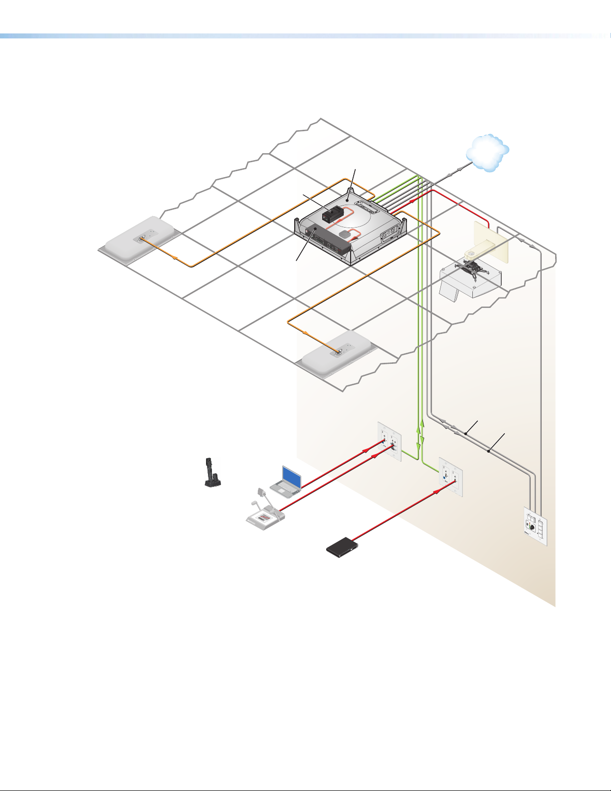
Application Diagram
The application diagram below shows a typical classroom installation incorporating the
VoiceLift System.
Extron
FF 120
Flat Field
Speakers
Extron
VLM 3002H
Pendant and
Handheld w/
Charging Station
Document
Camera
Laptop
Extron
VLR 302
VoiceLift
Receiver
Extron
PVS 407D
PoleVault
Switcher
EXTRON
VL
R 3
02
R
CONF
I
G
LINK
1
2
3
N
N
A
A
AN
L
L
L
N 1
A
L
G
N
I
G
R
A
O
P
NS
E
S
OUT
O
I
R
AUD
V
+
L
N 4
A
L
UT
O
UX
A
R
UDIO
N 2
A
5
D A
L
L
IE
UT
R
IF
P
L
N
P
I
AM
L
R
T
OT
V
N
D
O
N
IN
D
S
/8
U
R P
T
4
O
E
R
E
P
R
IR
C
V
Ω
L
G
HO
U
O
O
R
S
EC
N
T
R
F
E
O
AKE
S
S
I
E
T
T
G
G
P
UT
O
S
IN
TP
R
M
I
U
E
O
W
32
2
R
-
2
S
S
SGG
S
R
A
L
C
1
x
T
R
D
x
7
F
T
0
I
4
L
2
E
PVS
3
C
I
O
UT
4
V
P
OUT
5
A
UDI
6
O
7
A
UX
MI
D
H
S
6
I
UT
N
P
P
N
I
U
A
T
UD
MI
D
H
IO L
5
EV
EL
V
O
AD
IC
4
JU
/
ELIF
K
3
N
I
S
L
T
T
P
EA
G
I
S
K
2
/
K
1
NORMA
N
I
L
P
A
G
SEN
G
IN
S
SI
I
L
G
G
N
SO
A
IN
T
L
R
V
P
PE
ER
A
W
K
O
P
NORM
IN
X
P
PVS
T
A
O
V
12V
M
L
P
A
EVAU
-
SI
-
A
L
40
G
L
T
N
S
A
W
L
I
TC
Extron
PVT HDMI RGB
HDMI, RGB & Audio
Input Wallplate
Blu-ray
Extron
PVM 220
PlenumVault
Mounting Kit
7D
H
E
R
Extron
FF 120
Flat Field
Speakers
A
U
D
I
O I
N
H
D
M
I
IN
IR
O
UT
S
G
TCP/IP
Network
Ethernet
Short-throw
Projector
RS-232
to Projector
RS-232
to Switcher
A
U
IN
D
IO
OUT
VGA
I
N
LOC
A
L O
U
T
A
U
D
I
O I
N
H
D
M
I
I
N
A
U
D
I
O IN
IR
OUT
H
S
DM
I
G
I
N
Extron
PVT HDMI
Dual HDMI & Audio
Input Wallplate
Ethernet
D
ISPL
A
Y
ON
O
FF
V
O
L
U
M
E
C
O
N
F
I
G
Extron
MLC 104 IP Plus
MediaLink Controller
VCR
1
DVD
2
PC
3
4
M
L
C
104 IP P
L
U
S
Figure 1. Typical Room Installation
5
Page 14

VLM Kit Installation
3
AUDIO OUTPAGING
SENSO
R
O
IR
S
G
INPUT 5
3
PO
2V
1/2
SIG
LINK
INPUTS
PVT IN
OUTPUT
and Operation
This section covers the following topics:
• VoiceLift Pro Microphone Kit Overview
• Installing the VLC 302 Charger and Charging the Microphones
• Installing the VLR 302 Receiver
• Setting up the Microphones
• Pairing the Microphones with the VLR 302
• Setting up VLP 302 Instant Alerts
• Tips for Using the Microphones
VoiceLift Pro Microphone Kit Overview
The figure below shows the path of the audio signal through the VoiceLift System.
VLP or VLH Microphone
A
VLR 302 Receiver
B
MLC Controller
Connection
3
50 15.2
0.9
To Speakers
PoleVault Switcher
POWER
12V
1
3A MAX
A MAX
C
INPUTS
1/2
SIGLINK
WER
PVT IN
OUTPUT
PVS 407D
AMPLIFIED AUDIO OUT
DO NOT
GROUND
OR SHORT
4/8
SPEAKER
Ω
OUTPUTS
CLASS 2 WIRING
VOICELIFT
LR
REMOTE
RS-232
Tx Rx G
OVER PVT
VER PVT
AUDIO OUT
PAGING
13
SENSOR
R
L
R
INPUT 5
IR
L
L
SG
4
Figure 2. VoiceLift System Audio Signal Path
VLP or VLH Microphone — The VLP 302 and VLH 302 microphone transmits the
A
voice audio signal to the VLR 302 receiver.
VLR 302 Receiver — The VLR 302 receives the signal from the microphone, and
B
outputs a balanced mono line level signal (-10 dBV) to the PoleVault switcher.
PoleVault switcher — The PVS 407D PoleVault switcher functions as an amplifier
C
for the VoiceLift System. It amplifies the audio signal from the VLR 302 receiver and
sends it to the speakers. The switcher powers speakers placed throughout the room to
improve the signal-to-noise ratio of the voice to at least +15 dB.
VoiceLift Pro Microphones User Guide • VLM Kit Installation and Operation 6
Page 15
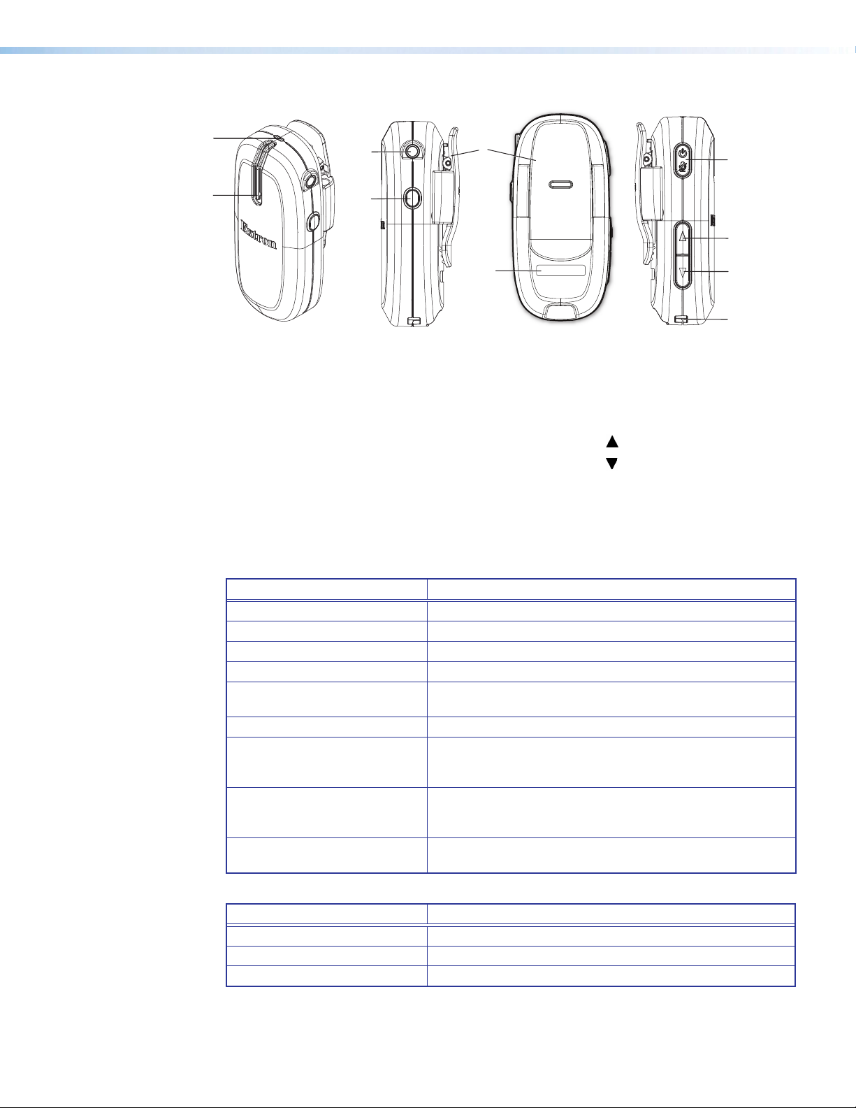
VLP 302 Microphone Features
G
I
J
B
A
c
E
D
H
F
Figure 3. VLP 302 Microphone Features
— Status LED (tri-color)
A
— Microphone acoustic ports
B
— Auxiliary microphone input (3.5 mm
C
mono female input jack)
— Function button
D
— Spring Clip
E
Status LED — This LED indicates the microphone power, volume, and charging status as
A
follows:
LED indicators when the microphone is powered on and in use:
— Microphone identification
F
label recess
— Power/mute button
G
— Volume button (increase)
H
— Volume button (decrease)
I
— Charging contacts
J
LED Color Indication
LED off Microphone is OFF or battery not installed
Green – steady Microphone ON
Green – slow blinking Microphone muted
Green – single blink Volume adjusted (increased or decreased)
Red – slow blinking Low battery (30 minutes or less of talk time left).
Recharge battery.
Red – steady Battery life depleted. Recharge battery.
Red – steady (5 seconds) Instant Alert activated. Volume Up and Down buttons
pressed and held simultaneously for 3 seconds (relay 1 triggered).
LED and relay revert states after 5 seconds.
Amber (flashes for 5 seconds) Function button activated.
Function button was pressed and held for 2 seconds (relay 2 is
triggered and latches to opposite state).
Red and green – alternate blinking
LED indicators when the microphone is charging:
LED Color Indication
Red – steady Battery charging
Green – steady Battery fully charged
Red and green – alternate blinking Incompatible, faulty or failed battery detected. Replace battery.
Microphone in discovery mode and attempting to pair with
receiver
Microphone acoustic audio input ports — The microphone receives voice audio through
B
these two acoustical ports. Do not block these ports while the microphone is in use.
VoiceLift Pro Microphones User Guide • VLM Kit Installation and Operation 7
Page 16

Auxiliary microphone input (Audio In) — Connect an auxiliary lavalier microphone
C
into this 3.5 mm mono auxiliary mic input jack. When an external lavalier microphone is
connected, the built in microphone elements in the VLP 302 are disabled.
Function button — When this button is pressed and held for two seconds, the
D
microphone signals the receiver to toggle Relay 2 to its opposite state.
NOTE: The status LED flashes amber for 5 seconds, indicating that the relay has
been toggled.
Also, when this button is pressed simultaneously with the Power button, it initiates Link
(pairing) mode.
Spring clip — Use this clip to attach the VLP 302 to clothing or to a lanyard (included)
E
(see step 4 on page 13 for instructions).
The lanyard lock is used to retain proper position of the microphone when clipped to
the lanyard. The breakaway clasps help to release the lanyard from around the neck if
it is pulled tightly. Place this clasp at the back of your neck when wearing the pendant
microphone.
Microphone identification label recess — Place the appropriate provided sticker in
F
this space to identify the microphone user (see step 3 on page 13).
Power and mute button (Off/Mute/On) — Press and hold the Power button (for
G
three seconds) to power the microphone on or off.
With the device on, press and release this button momentarily to mute or unmute the
microphone.
Volume buttons — Raise or lower the microphone volume.
HI
Pressing and holding both of these buttons simultaneously for 3 seconds sends a signal
to the receiver to close its Relay 1 port. This is typically used to trigger an alert (see
Setting up VLP 302 Instant Alerts on page 16).
Charging contacts — These make contact with the contacts in the charging station
J
when placed into the VLC 302. A full charge can take up to 5 hours.
VoiceLift Pro Microphones User Guide • VLM Kit Installation and Operation 8
Page 17

VLH 302 Microphone Features
A
B
E
F
C
+
D
Front Side
Figure 4. VLH 302 Microphone Features
Power Switch — Slide up to power on and down to power off.
A
Power Status LED — Dual color LED (green and red) indicates power or Link status.
B
LED indicators when the microphone is powered on and in use:
LED Color Indication
LED off Microphone is OFF or battery is not installed.
Green – steady Microphone ON and paired to receiver
Green – single blink Volume adjusted (increased or decreased).
Red – slow blinking Low battery (30 minutes or less of talk time left).
Recharge battery.
Red – steady Battery life depleted. Recharge battery
Red and green – alternating
blink
Microphone in discovery mode and attempting to pair
with receiver.
Rear
LED indicators when the microphone is charging:
LED Color Indication
Red – steady Battery charging
Green – steady Battery fully charged
Red and green – alternating
blink
Auxiliary Stereo Audio Input — 3.5 mm stereo input accepts line level audio signals,
C
but does not support external lavalier/lapel microphones. When an active aux input
device is connected, the built in microphone is disabled. The audio from the auxiliary
audio source is summed to mono and transmitted to the receiver.
Link button — This button is used to enable pairing mode.
D
Volume buttons — Increase ( ) or decrease ( ) the microphone volume.
EF
Incompatible, faulty, or failed battery detected.
Check and replace battery.
VoiceLift Pro Microphones User Guide • VLM Kit Installation and Operation 9
Page 18
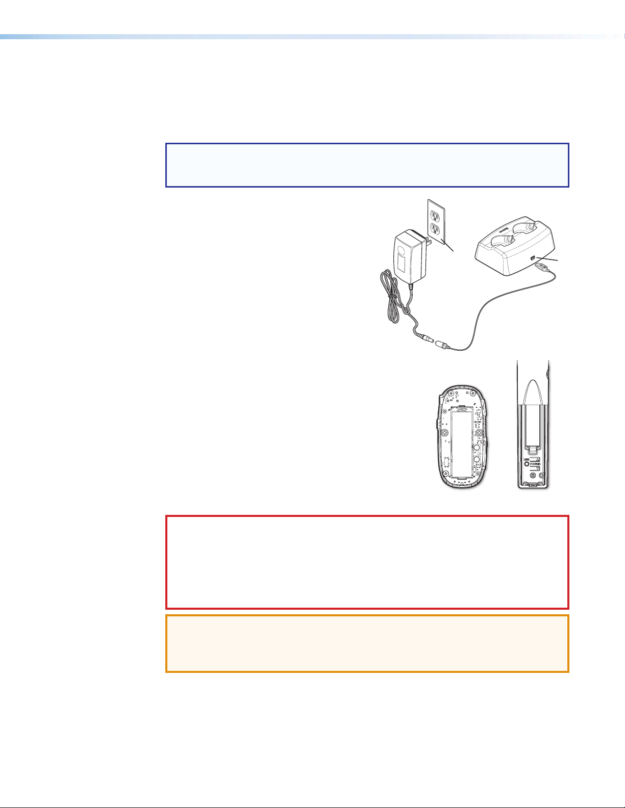
Installing the VLC 302 Charger and Charging the Microphones
(Cover Removed)
The VLC 302 charges the microphone battery. It is powered by an external wall power
supply (provided). The microphone battery requires up to 5 hours to charge fully. It is safe
to charge for extended periods, but Extron recommends storing the microphone out of the
charger with the battery removed.
NOTES:
• The charging station is to be used with NiMH rechargeable batteries only.
• Fully charge the supplied batteries before first use.
Follow these steps to connect the charger and
charge the microphones.
1. Connect the 5 VDC, 2.6 A wall charger
from a 110-130 VAC (U.S.) or a
100-240 VAC (international), 50-60 Hz
power source, to the mini B USB adapter.
2. Connect the USB mini plug end of the
adapter to the USB mini jack located on the
back of the VLC 302 (see 2 at right).
11
22
3. To install the battery, remove the microphone battery
cover as follows:
• VLP 302: Unscrew the two rear panel screws
located on either side of the rear clip.
• VLH 302: Slide the battery cover downward
_
+
until it stops, then lift the cover up and off the
microphone.
Insert the battery, aligning the + and – poles as
indicated inside the compartment.
+
VLP 302
(Cover Removed)
VLH 302
CAUTION: Use only NiMH rechargeable batteries provided by Extron when charging
the microphone. Use of any rechargeable battery other than the type provided by
Extron may cause explosion, chemical leakage, and injury.
ATTENTION : Utilisez uniquement les piles rechargeables de type NiMH fournies par
Extron, lorsque vous rechargez le microphone. L’utilisation d’une pile rechargeable
différente du type fourni par Extron peut présenter un risque d’explosion, de fuite de
substances chimiques, ou de blessure.
ATTENTION: Be sure to replace the battery with the correct type and to dispose of
used batteries appropriately.
ATTENTION: Assurez vous de remplacer les piles par le bon modèle et de jeter les
piles usagées de façon appropriée.
VoiceLift Pro Microphones User Guide • VLM Kit Installation and Operation 10
Page 19

4. Insert the microphone into one of the charger slots (4).
11
22
44
The microphone LED turns red when the microphone is
charging.
LED Color Indication
Red – steady Battery charging
Green – steady Battery fully charged
Red and green – alternate
blinking
NOTES:
• The microphone battery requires up to 5 hours to charge fully. It is safe to
charge for extended periods, but Extron recommends storing the microphone
out of the charger with the battery removed.
• Make sure that the microphones are fully seated in the charging station to
ensure proper charging.
ATTENTION:
• Do not charge alkaline batteries.
• Ne rechargez pas les piles alcalines.
• Use only Extron provided LPS type power supply charger for charging.
• Veuillez utiliser uniquement le bloc d’alimentation de type LPS fourni par Extron
pour la recharge.
Incompatible or failed
battery detected. Check
and replace battery.
LED
VoiceLift Pro Microphones User Guide • VLM Kit Installation and Operation 11
Page 20

Installing the VLR 302 Receiver
CD
A
B
1
3
A
T
PAGING
SENSO
R
DO NOT
GROUND
O
T
S
R
O
S
A
T
CLASS
G
4
Tx
R
G
O
T
I
S
G
INPUT
L
2
VLR 302 Receiver
PVS 407D PoleVault Switcher
The VLR 302 receiver outputs audio signals from the microphones as one balanced mono
line level signal to the PVS switcher or connected audio amplifier. In dual microphone
systems, the signals from the two microphones are mixed at the receiver and then output to
the connected audio amplifier.
Connect the VLR 302 to the PVS 407D PoleVault switcher as shown below. For mounting
options and instructions, see Step 1 — Mount the VLR 302 Receiver on page 19.
Connections
Figure 5. VLR 302 Front and Rear Panel
Reset button — Use this button to reset the receiver (see Resetting the VLR 302 on
A
page 32).
Mini USB configuration port — Connect a laptop or PC to this port using a suitable
B
USB cable for device configuration and firwmare updates only.
RJ-45 output connector — Connect the PVS 407D to this RJ-45 connector, using a
C
shielded RJ-45 cable as shown below.
NOTE: The receiver is powered by the PVS switcher. This connection also allows
for communication between the switcher and the receiver, to send configuration
commands and receive relay status information.
OVER PVT
VER PV
SG
IR
R
AUDIO OUT
UDIO OU
L
INPUT 5
L
PAGING
13
R
SENSOR
R
5
4
2
Out
AMPLIFIED AUDIO OUT
MPLIFIED AUDIO OU
DO NOT
GROUND
R SHOR
OR SHORT
PEAKE
SPEAKER
UTPUT
OUTPUTS
CLASS 2 WIRING
2 WIRIN
VOICELIFT
LR
Tx Rx G
x
Figure 6. The VLR 302 Rear Panel
Relays 1 and 2 (normally open/unlatched) — Wire this 4-pole captive screw connector
D
for relays 1 and 2 (see Setting up VLP 302 Instant Alerts on page 16).
• Relay 1 is triggered to close (latched) for 5 seconds when both volume buttons on
the microphone are pressed simultaneously for 3 seconds. The relay reverts back to
normally open once the 5 seconds has expired. Microphones must be configured
as "teacher" microphones to trigger relays.
• Relay 2 is triggered to close when the Function button on the microphone
(configured as "teacher") is pressed for 2 seconds. The relay stays closed (latched)
until the Function button is pressed and held again for 2 seconds.
VoiceLift Pro Microphones User Guide • VLM Kit Installation and Operation 12
Page 21

Setting up the Microphones
3
VLP 302 Pendant Microphone
1. Verify that the battery is installed and fully charged.
2. Set the microphone(s) for either "teacher" or "student" mode using the DIP switch,
accessible from beneath the battery cover (see 2 below):
• In teacher mode (default), all microphone
features are fully functional. Set the dip
switch to the OFF (down) position to
enable “teacher” mode.
• In student mode, all buttons are
disabled except for power. Set the
dip switch to the ON (up) position to
enable “student” mode.
3. Apply the appropriate label (provided) to identify the
microphone (see 3 at right).
4. To wear as a pendant microphone:
Push the lanyard into the guides on the
lanyard lock (see a at right).
Open the microphone clip (b).
Slide up the lanyard lock under the clip,
then release the clip (c).
2
a
b
Press to
open clip
Place the lanyard
around your neck and
adjust the
microphone position
by sliding it up so it
rests approximately
6 inches (15.2 cm)
~ 6
”
Lanyard
Lock
c
below your chin.
5. Turn the microphone(s) on by holding the power button for
Status
LED
5
three seconds.
NOTE: Each VLM kit includes microphones and a
VLR 302 receiver that have already been paired. If there
is a need to pair a microphone, follow the steps on the
6
next page.
6. Speak in a normal tone of voice, adjusting the volume level as
necessary.
7. When finished, return the microphone to the charging station.
VoiceLift Pro Microphones User Guide • VLM Kit Installation and Operation 13
Page 22

VLH 302 Handheld Microphone
A B
(Cover Removed)
A
1. Verify that the battery is installed and fully charged.
2. Turn the microphone on by sliding up the power
switch (see A at right).
NOTE: Each VLM kit includes microphones
and a VLR 302 receiver that have already
been paired. If there is a need to pair a
microphone, follow the steps in the next
section, below.
3. Speak in a normal tone of voice, adjusting the
volume level as necessary. The volume buttons are
located under the microphone cover (see B at right).
4. When finished, return the microphone to the charging station.
Pairing the Microphones with the VLR 302
Follow the steps below to pair microphones with a receiver, if necessary.
Verify which Microphones are Paired
Before pairing new microphones, follow these steps to verify which microphones are already
paired:
1. Ensure that the microphones are fully charged. Power
each microphone on, one at a time, to determine if the
microphones are paired to the VLR 302 receiver.
+
B
VLH 302
NOTES:
• As each microphone is powered on, one of
the VLR link slot LEDs (see A at right) will
illuminate if the microphone is paired.
2. Once you have determined which microphones are
• Only one microphone can be paired to each
LINK slot on the VLR receiver.
paired, turn them off.
Pair New Microphones
Follow the steps in this section to pair microphones to the VLR 302 receiver.
NOTES:
• All paired microphones must be turned off before pairing new microphones.
• If adding a new microphone to the system (or replacing a current microphone), and
both LINK slots are currently assigned, reset the VLR 302 to clear the paired history
(see Resetting the VLR 302 on page 32 for reset options).
• Clearing the paired history removes microphone LINK information from the VLR 302.
All microphones must be paired again, including any microphone that was previously
paired.
1. Press and hold the LINK button on the VLR 302 receiver (see B above) for 4 seconds to
start pairing mode. If LINK slots are available, one of the LINK LEDs blinks to indicate that
pairing mode has started.
VoiceLift Pro Microphones User Guide • VLM Kit Installation and Operation 14
Page 23

NOTES:
• Once initiated, pairing mode is enabled for 30 seconds. Users must repeat the
process if they have exceeded the 30 second pairing window or if pairing was
not successful.
• Receiver Pairing/Discovery mode can also be enabled remotely via SIS
comands.Commands can be sent to the receiver through direct USB
connection or through PVS switcher connection.
• If both LINK 1 and LINK 2 LEDs flash when initiating pairing mode on the
VLR 302, this means that both LINK slots are currently occupied and paired to
microphones.
2. Follow the steps below for your microphone model:
• For the VLP 302, ensure that the microphone is powered off.
NOTE: The VLP microphone must be in “teacher” mode (DIP switch in the
down position) in order to pair (see 2 on page 13).
Then, press and hold the
Power and Function
buttons (see A and B at
right) simultaneously for 4
seconds until the status
LED blinks red and green,
indicating pairing mode has
started.
• For the VLH 302:
Ensure that the microphone
is powered on.
NOTE: The VLH microphone must be in “student” (on)
mode in order to pair.
A
B
Then, press and hold the LINK button, located beneath the
3. After pairing the microphones, verify that they have been set up properly as shown in
battery cover (see C at right), for 4 seconds.
The microphone status LED changes from solid amber to alternating
red and green, indicating that pairing mode has started.
NOTE: The receiver assigns the microphone to the first available LINK slot. If the
microphone is paired successfully, one of the LINK LEDs on the VLR receiver lights
solid green.
Setting up the Microphones on page 13.
C
VoiceLift Pro Microphones User Guide • VLM Kit Installation and Operation 15
Page 24

Setting up VLP 302 Instant Alerts
Instant alerts can be triggered using VLP 302 pendant microphones set to "teacher" mode.
Press and hold both volume buttons simultaneously for 3 seconds to send a command to
close the normally open relay (Relay 1) on the receiver for a duration of 5 seconds. When
Relay 1 is closed, the status LED on the VLP microphone lights red to indicate the triggered
state.
This relay can be integrated with various life alert systems or connected to a control
processor, such as an Extron MediaLink MLC, to trigger an action (for example, sending an
email). After the 5 second pulse, the relay toggles back to the open state.
Example: Setting Up an Instant Alert
The following is an example of an optional instant alert, in which the VLR 302 relay port is
monitored through the MLC 104 IP Plus MediaLink Controller using Global Configurator. The
MLC can be configured to send an e-mail alert when the VLR relay port status changes.
This allows you to send out e-mail alerts from the classroom by holding down both Volume
buttons for three seconds (this action closes the relay on the VLR).
Step 1 - Configure the MLC 104 IP Plus
1. Open GC. Select your MLC 104 IP Plus, and then your PoleVault switcher.
2. Select the Monitor tab, and then click Add Monitor. The Monitored
Conditions Wizard window opens (see image below).
3. Follow the instructions at the top of the window: name the alert, then select a condition
(such as Relay On) and the action (send an e-mail message).
4. Complete the required monitor information (e-mail type and recipients) as desired, then
click Done. The alert is added to the Monitored Conditions list (see image below).
5. Build and upload the configuration.
NOTE: For full MLC configuration details, see the GC help file.
Step 2 - Test the instant alert notification
1. With the MLC 104 IP Plus connected to the network, press and hold the two Volume
buttons on the microphone simultaneously for 3 seconds. The receiver Link 1 and
Link 2 LEDs blink for the 5 second duration that Relay 1 is closed.
2. Check for the e-mail notification.
VoiceLift Pro Microphones User Guide • VLM Kit Installation and Operation 16
Page 25

Tips for Using the Microphones
• Speak in a normal tone of voice. When the microphone is set up properly, voice audio is
amplified just above ambient room noise.
• Mute or turn the microphone off while having private conversations.
• Return the microphones to the charging station when not in use. Verify that the
microphones are fully seated in the VLC 302 charger to ensure batteries are charged.
• If you are experiencing intermittent audio problems, check the batteries and replace
them if necessary. NiMH and alkaline batteries are supported.
CAUTION: Do not replace the battery with an incorrect type. Use only NiMh or
alkaline batteries.
ATTENTION : Ne pas remplacer la pile par le mauvais type de pile. Utilisez
seulement des piles de type NiMh ou alkaline.
ATTENTION:
• Do not recharge alkaline batteries.
• Ne rechargez pas les piles alkalines.
• Dispose of used batteries according to the instructions provided on the battery
packaging.
• Débarrassez-vous des piles utilisées selon les instructions du fabricant.
VoiceLift Pro Microphones User Guide • VLM Kit Installation and Operation 17
Page 26

VoiceLift System Installation
This section provides instructions for installing the VoiceLift System (VLS). Topics include:
• Recommended Installation Tools
• Step 1 — Mount the VLR 302 Receiver
• Step 2 — Mount the FF 120 Speakers
• Step 3 — Install the PVS 407D Switcher
• Step 4 — Connect the Receiver and Speakers to the Switcher
• Step 5 — Set up the Microphones and Test the System
Recommended Installation Tools
The following tools are recommended to complete the installation.
• Laser level, or two levels (large level for
screen installation; small level for wall
plates and projector mounts)
• Tape measure
• Stud finder
• Drill and drill bit set, including a unibit to
cut through metal studs
• Extension drill bit (3/4 inch min., 4 to 8
foot length, to drill through fire breaks)
• Socket set
• Pipe strap or wrapped pipe wrench
• Pliers and wire strippers
• Standard screwdriver set and Extron
Tweeker
• Cable cutters (to cut safety wire)
• Drywall saw and hacksaw blade
mounted on handle (for cutting ceiling
tiles)
• Flashlight and safety goggles
• Razor knife
• 2 inch hole saw
• Painter’s tape (to mark up walls), pencil,
and marker pen
• RJ-45 crimpers and RJ-45 connectors
• Voltage tester
• Fish tape, pull string, and electrical tape
(for taping fish tape to pull string)
• Zip ties
• Vacuum cleaner
• Heat gun
Other Hardware Items
Some or all of the following installation hardware may be needed for the installation at your
particular site (may vary by installation):
• Electrical ceiling box
• Junction box
• Plaster ring
• Raceway
• Bolts for concrete structural
ceilings where needed
• Drywall anchors and screws
• Spare ceiling tiles in case of accidental
damage during installation
• Safety wire, lag eye bolts, and strain reliefs
• Heat shrink
• Extension cord
VoiceLift Pro Microphones User Guide • VoiceLift System Installation 18
Page 27
Step 1 — Mount the VLR 302 Receiver
Rack Mounting
The receiver includes 1/8 rack mounting holes for mounting directly to a rack shelf or
architectural enclosure that supports standard Extron mounting hole patterns.
UL Guidelines for Rack Mounting
The following Underwriters Laboratories (UL) guidelines are relevant to the safe installation of
this product in a rack:
• Elevated operating ambient temperature — If the unit is installed in a closed or
multi-unit rack assembly, the operating ambient temperature of the rack environment
may be greater than room ambient temperature. Therefore, install the equipment in an
environment compatible with the maximum ambient temperature
(TMA = +122 °F, +50°C) specified by Extron.
• Reduced air flow — Install the equipment in the rack so that safe operation and
adequate air flow is provided to the unit.
• Mechanical loading — Mount the equipment in the rack so that a hazardous
condition is not achieved due to uneven mechanical loading.
• Circuit overloading — Connect the equipment to the supply circuit and consider the
effect that circuit overloading might have on overcurrent protection and supply wiring.
Consider the equipment nameplate ratings when addressing this concern.
• Reliable earthing (grounding) — Maintain reliable grounding of rack-mounted
equipment. Pay particular attention to supply connections other than direct
connections.
Rack Mounting Procedure
The receiver can be mounted on optional rack systems listed on the website (see
www.extron.com). To mount the unit on a rack shelf, follow the instructions provided with
the shelf accessories.
Extron
USFM 100
Back of the Rack Mounting Procedure
The receiver can be mounted to the rear of a rack using an optional back of rack mounting
kit (see www.extron.com). The kit allows the product to be vertically mounted to the front
or rear rack supports and face either the front or the rear of the rack. To mount the unit,
follow the instructions provided with the kit.
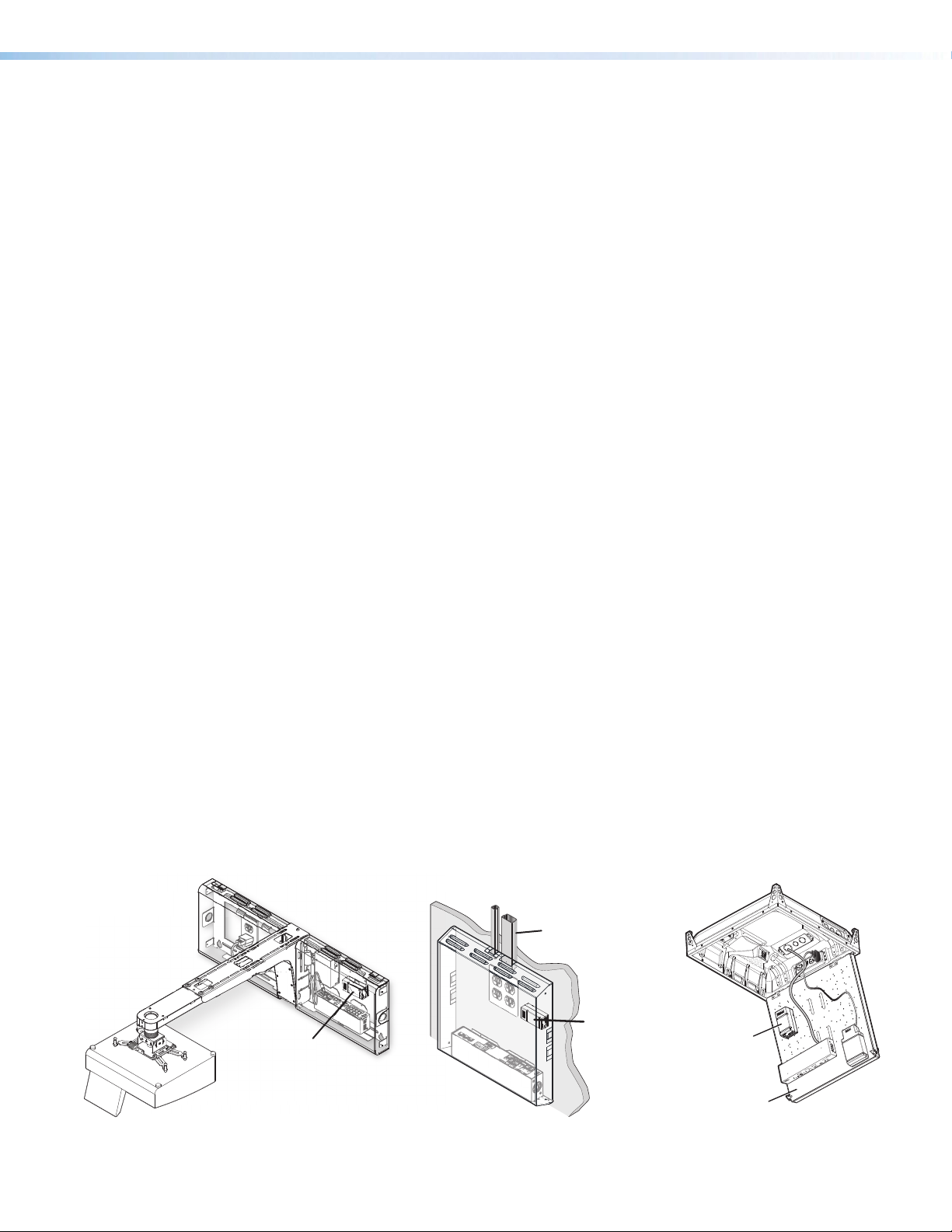
The VLR 302 can be mounted within the USFM 100, WMK 160 and PVM 220, as shown
below (see the PoleVault Digital System Installation Guide for details).
V700
2400
Raceway
Option
Extron
PVM 220
VLR 302
VLR 302
Extron
WMK 160
Enclosure
VLR 302
Access Door
E
IP
R
A
HE
S
C
5
0
WIT
4
S
T
S
L
U
V
A
P
V
E
L
O
P
G
N
OR
S
Y
AGI
N
T
P
E
VI
S
ST
I
T
I
U
S
N
E
DJ
S
A
L
L
K
E
A
A
E
M
P
R
L
O
A
N
EV
N
G
I
L
S
O
I
T
F
LI
E
UD
C
I
O
A
V
L
A
M
R
O
K
N
L
A
A
E
N
P
G
I
S
T
U
P
N
I
O
I
D
5
U
X
A
U
A
S
UT
NP
I
3
4
1
2
T
C
ELE
S
G
I
F
N
O
C
R
Figure 7. VLR 302 Rack Mounting Options
VoiceLift Pro Microphones User Guide • VoiceLift System Installation 19
Page 28

Zip Clip Mounting
1
2
End Section
24" x 48" Ceiling Tile 24" x 24" Ceiling Tile
Using the ZipClip 100 (optional)
To attach the receiver to the ZipClip 100 mounting clip:
1. Insert the bottom of the receiver down into the
clip, starting with one end.
2. Pivot the other end down and press until
the clip snaps into place.
To remove the receiver from the ZipClip:
1. Press the tab on the ZipClip.
2. Pivot the receiver and lift it out of the ZipClip.
To fasten the tie wraps for cable strain relief:
1. Attach the receiver to the ZipClip 100 mounting
clip as described previously.
2. Fasten the cables to the ZipClip base.
a. Insert tie wraps (“zip ties”) along the
b. Connect and pull the tie wraps until they
notches on the side of the receiver and
through the tie wrap anchor points on the
ZipClip, then around the cord.
are secure. Do not over tighten.
Tie Wrap
1
2
Cable
Strain
Relief
Step 2 — Mount the FF 120 Speakers
The FF 120 speakers are installed in ceiling tiles. They receive and output the audio signal
from the PVS 407D switcher.
Follow the steps below to install the FF 120 speakers.
NOTE: The installation must conform to national and local electrical codes and UL
requirements (see the FF 120 Flat Field Speakers User Guide for details).
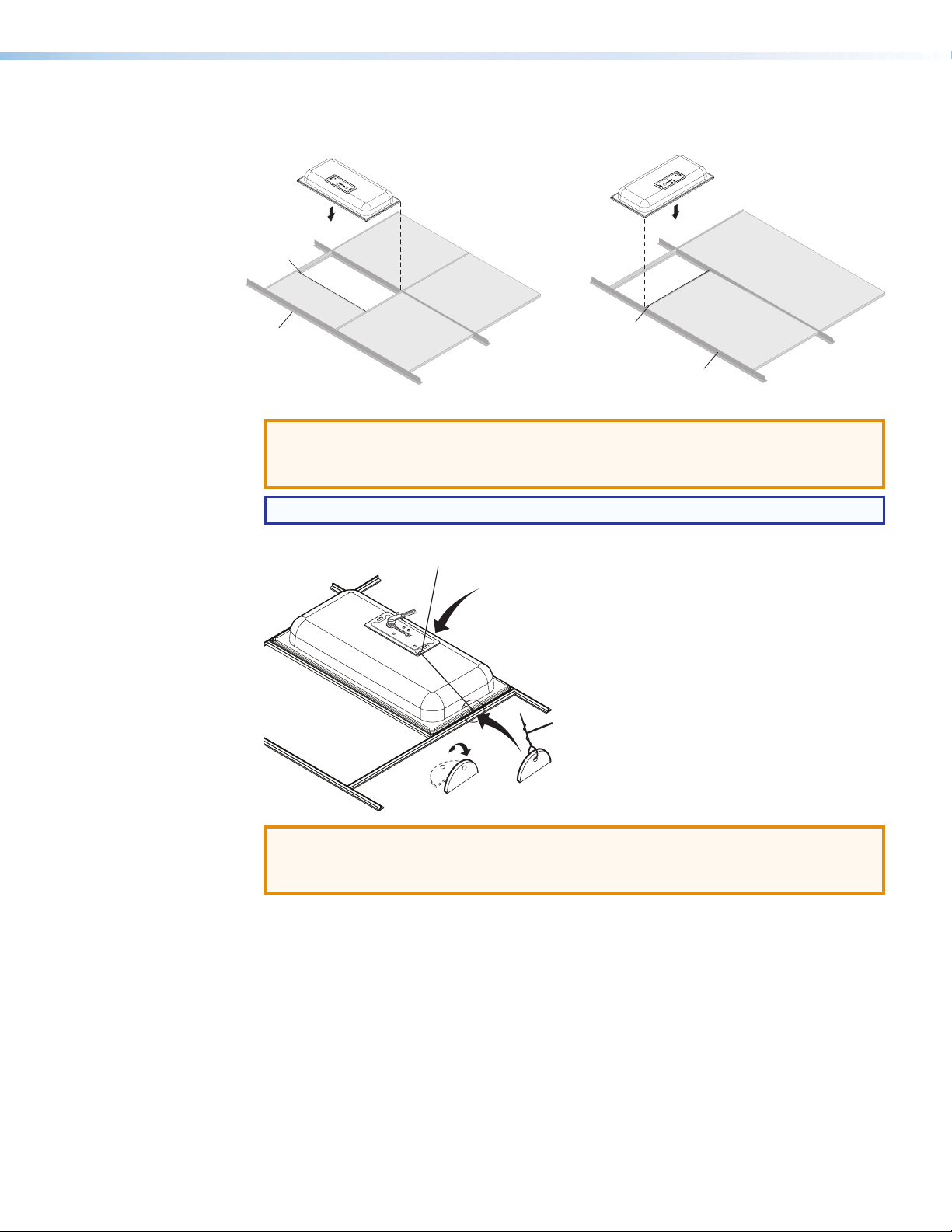
1. Remove and cut ceiling tile —
Remove the ceiling tile where the
FF 120 will be installed. Cut out a
12-inch section from either end of
the tile where the speaker will be
installed, as shown at right.
2. Install the T-rail — Install the
T-rail crosspiece into the ceiling
opening up against the cut tile, as
shown at right.
24"
Draw line.
12"
48"
T-rail (1)
Cut material.
12"
24"
24"
VoiceLift Pro Microphones User Guide • VoiceLift System Installation 20
Page 29
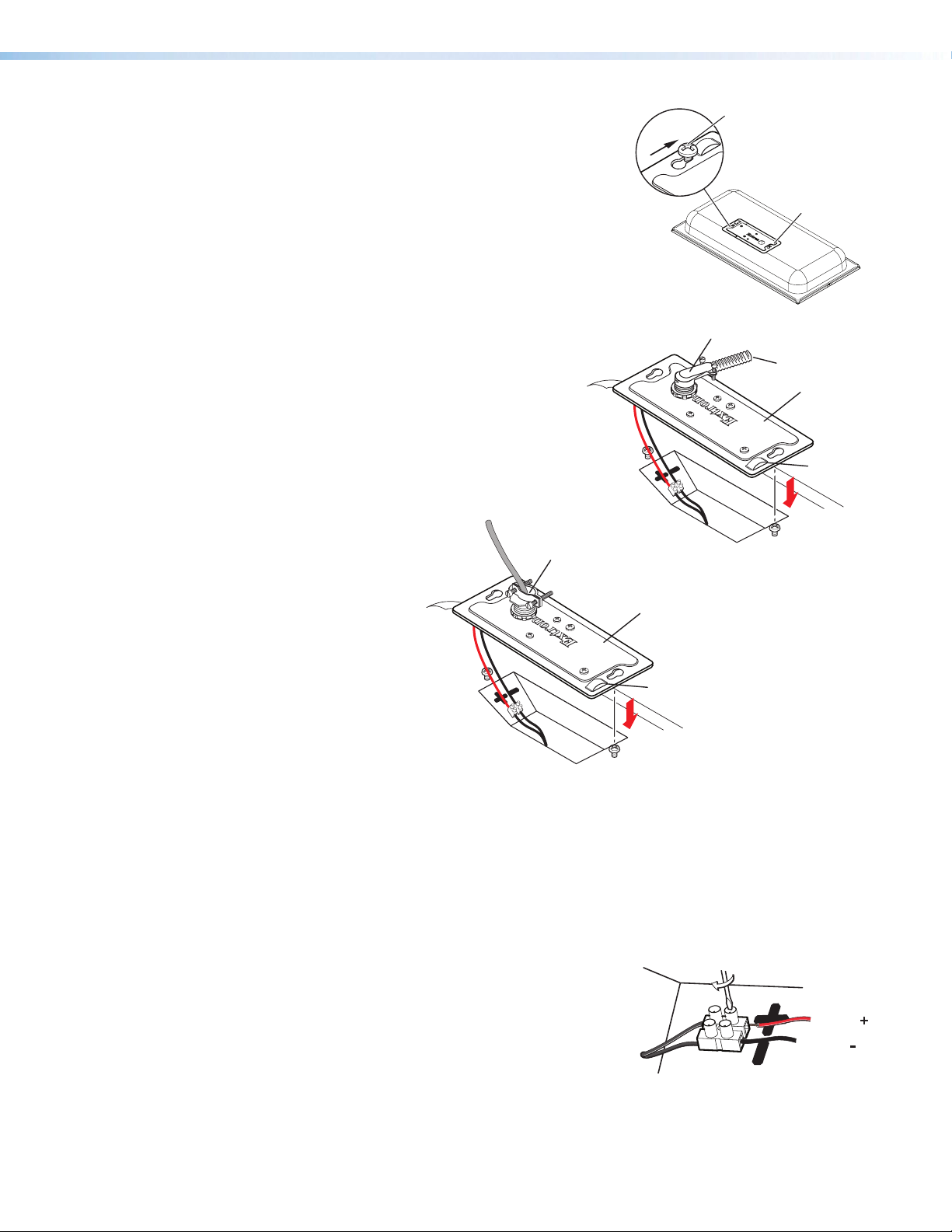
Loosen, do not remove.
3. Cover plate — Loosen, but do not remove, the two
screws on the top of the cover plate, as shown on the
right. Next, slide and remove the cover plate.
Cover Plate
Flexible Conduit Adapter
4. Using Flexible Conduit — When using flexible
conduit, insert the conduit into the cover plate
opening using an appropriate conduit adapter,
Flexible Conduit
Cover Plate
and secure the conduit adapter to the plate, as
shown at right.
Secondary
Attachment
Point
When using speaker wires without a conduit,
secure the cable clamp
adapter (included)
to the cover plate and insert
Cable Clamp Adapter
Rear of Speaker
the wires through the
clamp. Tighten the
screws, as shown
Cover Plate
below.
Rear of Speaker
Secondary
Attachment
Point
5. Wire the speaker —
a. Pull the wires from the amplifier through and out of the conduit, if a conduit is used.
b. Route the two wires from the amplifier through the cover plate hole. See the wire gauge
table on page 1.
c. Strip 3/16 inch (5 mm) from the ends of the two speaker wire leads (+ and -) coming
from the amplifier. Keep the wire strands together by twisting them (do not tin the wires),
and secure the wires to the input terminals of the speaker while observing the correct
polarity.
d. Connect the red, positive (+) wire to the + speaker
terminal and connect the black, negative (-) wire to
the - speaker terminal, as shown at right.
Red Wire
From Amplier
Black Wire
6. Replace the cover plate and tighten the two cover plate screws that were loosened in step 3.
VoiceLift Pro Microphones User Guide • VoiceLift System Installation 21
Page 30
7. Set the speaker on top of a T-rail making sure to hide the edges behind the grid rail, as
Extr
FF 120
Ceiling
Speakers
Route the secondary support cable
shown below.
Extron
FF 120
Ceiling
Speakers
T-rail (1)
Ceiling Tile
Rails
2' by 2' Ceiling Tiles
Ceiling Tile
on
Ceiling Tile
T-rail (1)
2' by 4' Ceiling Tiles
Ceiling Tile
Rails
8. If secondary support cables are being used, install them (see the illustration below).
ATTENTION:
• DO NOT allow any slack in the support cables.
• Ne laissez aucun jeu entre les câbles de support.
NOTE: Observe all applicable building codes and local ordinances when installing the speaker.
Anchor this end to a
suitable secure point.
through the secondary attachment
point and bend up the tab.
Bend up Tab
Secondary
Support
Cable
ATTENTION:
• Repeated bending of the tab may cause it to break off.
• Le fait de plier l’attache de façon répétitive peut la casser.
a. Temporarily remove a ceiling tile adjacent to the speaker and set it aside.
b. Connect a secondary support cable through the secondary attachment point, and attach
it to one of the tabs located on either side of the speaker.
c. Attach the other end of the cable to a sturdy part of the building (studs, roof struts, and
so on).
d. Repeat as needed for additional secondary support cables.
e. Replace the ceiling tile removed in step 8a.
9. Check all wiring before powering up the amplifier.
VoiceLift Pro Microphones User Guide • VoiceLift System Installation 22
Page 31
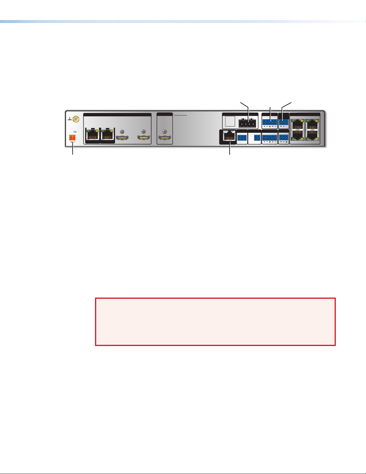
Step 3 — Install the PVS 407D Switcher
The PVS 407D PoleVault Switcher receives input video and audio signals from the AV
source input wallplates, and audio signals from the VoiceLift VLR 302 receiver. It outputs and
switches the video and audio signals to a display and speakers. For details, see the PoleVault
Digital Systems Installation Guide (Featuring the PVS 407D Switcher), included with the
switcher and available at www.extron.com.
LR
OVER PVTREMOTE
Audio Out
Port
AUDIO OUT
L
INPUT 7
IR
L
SGG
LAN
13
+V
24
LAN
PAGING
SENSOR
R
AUX
R
1/2
POWER
12V
3A MAX
SIGLINKSIG LINK
3/4
PVT IN PVT IN
Power Supply Connector
INPUTS
Output to Speaker Paging Sensor Port
PVS 407D
OUTPUT
5
HDMI
6
HDMI
AMPLIFIED AUDIO OUT
DO NOT
GROUND
OR SHORT
4/8
SPEAKER
Ω
OUTPUTS
CLASS 2 WIRING
VOICELIFT
RS-232
Tx Rx
VoiceLift Receiver Port
Figure 8. PVS 407D Switcher
PoleVault Switcher Installation
1. Determine a location within the room for the PVS 407D switcher (see PoleValut Switcher
Location below).
2. Install the PVS 407D, following the instructions in the PoleVault Digital Systems Installation
Guide (Featuring the PVS 407D Switcher) and the provided mounting kit user guide.
3. Make sure that the PVS 407D front and rear panels are accessible until installation and
testing of the VoiceLift System is complete.
PoleVault Switcher Location
The PoleVault switcher can be mounted anywhere in the room. However, placing the switcher
near the ceiling makes cabling and upgrading to a full PoleVault system easier. WallVault
and PlenumVault options are also available for wall or plenum ceiling mount applications (for
installation instructions, see the installation guides for each system).
WARNING: Structural ceiling failure could cause serious injury or death. Check the
structural ceiling to ensure that it can handle a load four times the weight of the final
setup.
AVERTISSEMENT : Un défaut dans la structure du plafond pourrait provoquer des
blessures graves voire mortelles. Vérifier la structure du plafond afin de vous assurer qu’il
peut supporter une charge quatre fois supérieure au poids de l’installation finale.
Possible switcher mounting locations include:
• Table top, cabinet, or shelf (attach the four provided rubber feet to the bottom of the unit)
• Under a desk
• Mounted to a wall with an Extron WMK 160 or USFM 100 WallVault Wall Mount Kit
• Above a drop ceiling using the Extron PlenumVault PVM 220
VoiceLift Pro Microphones User Guide • VoiceLift System Installation 23
Page 32

Step 4 — Connect the Receiver and Speakers to the PoleVault Switcher
Receiver
A
NOTES:
• Use CATx shielded twisted pair STP cable with
T568A or T568B straight-through wiring.
• The connection to the PoleVault switcher powers
the receiver, and enables communication and audio
between the receiver and the switcher.
1. Pull cables to the receiver, along with any other cables
that will be attached to the receiver (such as relay
connectors).
2. Connect the STP cable to the receiver Out (RJ-45) port
(see A at right).
3. Connect the cables to the PoleVault Switcher as follows:
a. Disconnect the power cable from the PoleVault switcher.
b. Plug the STP cable into the VoiceLift RJ-45 port on the switcher (see Ý below).
c. Connect cable from the speakers to the Amplified Audio Out connector on the
switcher (see Þ below).
d. Reconnect the power cable to the switcher.
Audio Output
Þ
to Speakers
Speaker
Wire Color
PVS Terminal
(Left and Right)
Red Positive (+)
Black
Negative (–)
PVS 407D
INPUTS
1/2
3/4
POWER
12V
3A MAX
SIG LINK SIG LINK
PVT IN PVT IN
5
HDMI
OUTPUT
6
HDMI
Ý
AMPLIFIED AUDIO OUT
DO NOT
GROUND
OR SHORT
SPEAKER
OUTPUTS
CLASS 2 WIRING
VOICELIFT
VoiceLift
4/8
Ω
RS-232
Tx Rx
LR
OVER PVTREMOTE
AUDIO OUT
PAGING
SENSOR
L
R
AUX
INPUT 7
IR
L
R
SGG
13
+V
24
LAN
LAN
Figure 9. Connecting the Speakers and Receiver to a PVS 407D Switcher
VoiceLift Pro Microphones User Guide • VoiceLift System Installation 24
Page 33

Step 5 — Set up the Microphones and Test the System
1. Set up each microphone in the VoiceLift system (see Setting up the Microphones on
page 13).
2. Set the microphone gain:
a. Power on the VoiceLift system. The Power LEDs on the microphone and receiver light
green.
b. Instructor: Place the lanyard with the pendant microphone around your neck and
adjust the lanyard as shown in step 4 on page 13.
Student: Hold the VLH handheld microphone approximately 4 inches (10.2 cm) from
your mouth. Turn off all program audio sources.
c. On the VLP microphone, raise the volume to maximum by pressing and holding
the Volume button. A double beep tone indicates that maximum volume has been
reached. There are five volume steps available.
d. On the PoleVault switcher,
while testing the microphone,
press the VoiceLift adjust
buttons to increase or
decrease the microphone
input gain. Adjust the input
gain level until an acceptable
maximum level is reached.
The Signal and Normal LEDs
(see image at right) are lit
when speaking in a normal voice.
If there is feedback, lower the VoiceLift input gain on the switcher until feedback stops.
e. Walk around the room while talking into the microphone. If feedback occurs, lower the
VoiceLift input gain on the switcher and then walk around the room again, talking into
the microphone.
NOTE: The highest gain achieved without feedback is the maximum gain for the
VoiceLift system.
INPUT
AUDIO LEVEL ADJUST
VOICELIFT
PEAK
NORMAL
SIGNAL
Press the VoiceLift buttons
to raise or lower the gain
PEAK
NORMAL
SIGNAL
PAGING
SENSOR
PVS 407D
POLEVAULT SWITCHER
f. On the microphone, lower the volume to an appropriate level:
• The level of your speaking voice should be enhanced, but not loud enough to sound
like a paging system.
• Check the LEDs on the PVS switcher. The green Normal LED should light when you
speak, with the red Peak LED blinking occasionally.
Level set too high.
PEAK
NORMAL
SIGNAL
Lower input gain.
Level has been
properly adjusted.
Signal threshold
-20 dBV (-18 dBu)
NOTE: The microphone audio should be slightly audible to the person speaking
into it. Have another person listen for the audio levels and check for sound
quality.
3. Test any optional devices that have been installed.
VoiceLift Pro Microphones User Guide • VoiceLift System Installation 25
Page 34

SIS Configuration and Control
This section provides information on how to configure the VoiceLift system using Extron
Simple Instruction Set (SIS) commands. It provides a list and descriptions of the available
commands. Topics include:
• Overview
• Host to Receiver Communication
• Commands and Responses
• Command and Response Table for SIS Commands
NOTE: The VoiceLift System can also be configured using the Extron Product
Configuration Software (PCS). For full details about using PCS, see the PVS 407D
PoleVault Digital Switcher User Guide available online at www.extron.com, or the
PCS help file, embedded in the PCS software.
Overview
The VLR 302 receiver can be controlled via a host computer that is connected to the USB
control port on the VLR 302 receiver. Commands can be sent from the computer using a
communication software program such as Extron DataViewer. SIS commands are available
for various functions, such as obtaining information and status for the VLR 302 ports,
controlling relay functions, pairing, and resetting the VLR 302.
Host to Receiver Communications
SIS commands consist of one or more characters per field. No special characters are
required to begin or end a command sequence. When the VLR 302 recognizes a valid
command, it executes the command and sends a response to the host device. All responses
from the receiver to the host end the character string with a carriage return and a line feed
(CR/LF = ]). A string is one or more characters.
Error Response
When the VLR 302 receives a valid SIS command, it executes the command and sends a
response to the host device. If the receiver is unable to execute the command because the
command is invalid or contains invalid parameters, it returns the following error response to
the host:
E13 – Invalid value (the number is out of range)
Timeout
A pause of 10 seconds or longer between command characters results in a timeout. The
command operation is aborted with no other indication.
VoiceLift Pro Microphones User Guide • SIS Configuration and Control 26
Page 35

Commands and Responses
Space
Using the Command and Response Table
The Command and Response Table for SIS Commands on page 28 lists the following:
• Valid ASCII command codes
• The receiver responses to the host
• A description of the command function, or the results of executing the command
The ASCII to hexadecimal conversion table below is for use with the command and
response table:
ASCII to Hex Conversion Ta ble
Upper- and lowercase characters can be used interchangeably in the command field unless
otherwise specified.
•
Symbol Definitions
= Carriage return and line feed (LF)
]
= Carriage return with no line feed
}
| =
Pipe (can be used interchangeably with the } character).
= Space
•
= Escape key
E
W
=
Can be used interchangeably with the E character.
= On and Off status
X@
0 = off/disable/open (default)
1 = on/enable/closed
= Firmware version number
X#
= Verbose mode
X$
0 = disabled
1 = verbose mode (default)
2 = tagged responses for queries
3 = verbose mode and tagged responses for queries
=
X%
X&
X*
Pulse time in 256 ms counts
If parameter is missing or = 0, then the pulse length is default = 2 = 512 ms.
Max = 255 65280 ms ≈ 65 seconds
= Relay
1 = Relay 1
2 = Relay 2
= Chime
0 = Off
1 = On (default)
VoiceLift Pro Microphones User Guide • SIS Configuration and Control 27
Page 36

= View Paried Microphones
X(
0 = Microphone Not Occupied or Pairing Failed
1 = Link slot occupied
9 = Reciever is unable to enter pairing mode. A previously paired microphone is
on and connected; or both LINK slots are already occupied.
= Initiate Pairing mode
X1)
1 = Pairing initiated
99 = Pairing mode failed; receiver is busy or in use.
Command and Response Table for SIS Commands
Command
ASCII Command
(Host to Receiver)
Status
View microphone usage (hours) E
Reset microphone usage E
USAG} UsagXXXXX:XX
0USAG} Usag00000:00
NOTE: Maximum hours up to five characters (ex. 12345:15).
Relay Functions
Pulse relay
Toggle relay
Force relay ON
Force relay OFF
View relay state
X&
*3*X%O RlyX&*
X&
*2O RlyX&*
X&
*1O RlyX&*1
X&
*0O RlyX&*0
X&
*O RlyX&*
Chime
Set Audible Chime
View Audible Tone
EX*
CHIM} Chim
E
CHIM} Chim
Pairing
Initiate Pairing mode E
View Paired E
Clear Paired
E
1PAIR}
PAIR} Pair
0PAIR} Pair0
Response
(Receiver to Host)
Pair
X@]
X@]
]
]
X@]
X*]
X*]
X1)]
X(X(]
]
]
]
Additional Description
Format is in number of hours and minutes
(HHHHH:MM).
hours is five digits (ex. XXXXX:XX). Minutes are in
increments of 15. Maximum value is “99999:45”
"View Paired" response indicates whether
microphones are paired to each LINK slot. The
first X( variable represents LINK slot 1; the
second X( variable represents LINK slot 2. For
example, "Pair11" Indicates that microphones
are paired to both LINK slots 1 and 2.
Maximum character limit for
Verbose Mode
Set verbose mode
View verbose mode
EX$
CV} Vrb
E
CV} Vrb
Reset
Reset Esc ZXXX} Zpx
Information Requests
Request part number
Query firmware version
Example:
Query updated firmware version
Request model name
N
Q or 1Q
Q
20Q
1I
60-1637-01VL
X# ]
1.01
X# ]
VLR • 302
VoiceLift Pro Microphones User Guide • SIS Configuration and Control 28
X$]
X$]
]
]
] Show part number of the VLR 302 receiver.
Show the VLR 302 firmware version (X#) to
two decimal places.
Show the version of firmware that was
uploaded by the user to the receiver.
]
Show the receiver product name.
Page 37

Reference Information
This section provides the following reference information:
• Updating Firmware with Firmware Loader
• Resetting the VLR 302
Updating Firmware with Firmware Loader
To upload and update firmware for the VLR 302, download the new firmware to a
connected computer and upload the firmware with the Extron Firmware Loader utility.
Downloading Extron Firmware Loader
1. On the Extron website, click the Download tab (see figure 10, 1, below).
2. From the left sidebar, click the Software link (see figure 10, 2). A list of available
software opens.
Figure 10. Downloading Software from the Extron Website
3. Navigate to Firmware Loader (see figure 11, 1).
Figure 11. Firmware Loader on the Extron Website
4. Click the Download link on the right that corresponds with the program (see figure 11,
).
2
5. Submit any required information to start the download.
VoiceLift Pro Microphones User Guide • Reference Information 29
Page 38

Installing Firmware Loader
1. Once Firmware Loader has been downloaded, run the .exe file from the location where
the file was saved. The installation window opens.
2. Follow the instructions on the installation screens to install Firmware Loader on the
computer.
Downloading Firmware
Figure 12. Downloading Firmware from the Extron Website
1. On the Extron website, click the Download tab (see figure 12, 1).
2. From the left sidebar, click the Firmware link (2).
3. Navigate to VLR 302.
4. Ensure the available firmware version is a later version than the current one on the
device.
NOTE: The firmware release notes are a PDF file that provides details about the
5. Click the Download link to the right of the desired device.
6. Submit any required information to start the download. Note where the file is saved.
7. Run the executable file (.exe file extension) and follow the on-screen instructions to
changes between different firmware versions. The file can be downloaded from the
same page as the firmware.
place the firmware file and release notes on the PC. Note where the file is saved.
VoiceLift Pro Microphones User Guide • Reference Information 30
Page 39

Installing Firmware with Firmware Loader
1. Connect the host device to the front panel USB port.
2. Open Firmware Loader and establish a connection between the computer and the
device. The Add Device... dialog box opens.
Figure 13. Add Device... Dialog Box
3. From the Device Name drop-down list, select VLR 302.
4. From the Connection Method drop-down list, select USB.
5. Make the appropriate selections for the current connection method.
6. Click the Connect button.
7. In the New File Firmware (Optional) panel, click Browse. The Open dialog box
opens.
8. In the Open dialog box, navigate to the location of the new firmware file and select the
desired file.
ATTENTION:
• Valid firmware files must have the file extension .S19. A file with any other
extension is not a firmware upgrade for this device and could cause the device
to stop functioning.
• Les fichiers firmware valides doivent contenir l’extension fichier S19. Un fichier
avec n’importe quelle autre extension n’est pas une mise à jour de firmware
pour cet appareil et l’appareil pourrait arrêter de fonctionner.
9. Click Open. The Browse dialog box closes.
10. Click Add. The Add Device... dialog box closes and the device and firmware are
listed in the Firmware Loader main window.
11. Click Begin to start the upload process.
12. Close Firmware Loader when the Remaining Time field shows 00:00:00, the
Progress column shows 100%, and the Status field shows completed.
VoiceLift Pro Microphones User Guide • Reference Information 31
Page 40

Resetting the VLR 302
Follow the steps below to reset the VLR 302 receiver using the front panel Reset button
(see A on page 12). The VLR 302 may also be reset using the Product Configuration
Software (see the help file for the VLR 302 module within PCS).
NOTE: All paired microphones must be turned off in order to properly reset the VLR 302
receiver.
Reset Mode 1
This mode resets the unit to its base factory firmware.
Hold down the Reset button while the switcher is being powered up. The receiver boots
to its base factory firmware. Any firmware that has been loaded over the base firmware is
ignored.
Reset Mode 2
This mode resets pairing history, but retains settings and usage data.
1. Hold down the Reset button for about three seconds until the Power LED blinks once.
2. Release and press the Reset button momentarily (for less than one second) within one
second.
3. Both LINK 1 and LINK 2 LEDs flash one time, simultaneously, to confirm that the pairing
history has been cleared. Unsolicited response “Pair00” is sent.
Reset Mode 3
This mode is an absolute factory reset. It will default the unit back to factory settings, and
also clear pairing and usage data.
1. Hold down the Reset button for about six seconds until the Power LED blinks two
times.
2. Release and press the Reset button momentarily (for less than one second) within one
second.
Front panel LEDs will cycle, and all settings (including pairing history) will be cleared from the
unit. This reset is the same as sending the ‘ZXXX’ SIS command.
VoiceLift Pro Microphones User Guide • Reference Information 32
Page 41

Extron Warranty
Extron Electronics warrants this product against defects in materials and workmanship for a period of three years
from the date of purchase. In the event of malfunction during the warranty period attributable directly to faulty
workmanship and/or materials, Extron Electronics will, at its option, repair or replace said products or components,
to whatever extent it shall deem necessary to restore said product to proper operating condition, provided that it is
returned within the warranty period, with proof of purchase and description of malfunction to:
USA, Canada, South America,
and Central America:
Extron Electronics
1230 South Lewis Street
Anaheim, CA 92805
Japan:
Extron Electronics, Japan
Kyodo Building, 16 Ichibancho
Chiyoda-ku, Tokyo 102-0082
Japan
U.S.A.
Europe and Africa:
Extron Europe
Hanzeboulevard 10
3825 PH Amersfoort
The Netherlands
China:
Extron China
686 Ronghua Road
Songjiang District
Shanghai 201611
China
Asia:
Extron Asia Pte Ltd
135 Joo Seng Road, #04-01
PM Industrial Bldg.
Singapore 368363
Middle East:
Extron Middle East
Dubai Airport Free Zone
F12, PO Box 293666
United Arab Emirates, Dubai
Singapore
This Limited Warranty does not apply if the fault has been caused by misuse, improper handling care, electrical
or mechanical abuse, abnormal operating conditions, or if modifications were made to the product that were not
authorized by Extron.
NOTE: If a product is defective, please call Extron and ask for an Application Engineer to receive an RA (Return
Authorization) number. This will begin the repair process.
USA: 714.491.1500 or 800.633.9876 Europe: 31.33.453.4040
Asia: 65.6383.4400 Japan: 81.3.3511.7655
Units must be returned insured, with shipping charges prepaid. If not insured, you assume the risk of loss or damage
during shipment. Returned units must include the serial number and a description of the problem, as well as the
name of the person to contact in case there are any questions.
Extron Electronics makes no further warranties either expressed or implied with respect to the product and its quality,
performance, merchantability, or fitness for any particular use. In no event will Extron Electronics be liable for direct,
indirect, or consequential damages resulting from any defect in this product even if Extron Electronics has been
advised of such damage.
Please note that laws vary from state to state and country to country, and that some provisions of this warranty may
not apply to you.
Extron Headquarters
+1.800.633.9876 (Inside USA/Canada Only)
Extron USA - West Extron USA - East
+1.714.491.1500 +1.919.850.1000
+1.714.491.1517 FAX +1.919.850.1001 FAX
Extron Europe
+800.3987.6673
(Inside Europe Only)
+31.33.453.4040
+31.33.453.4050 FAX
© 2017 Extron Electronics All rights reserved. www.extron.com
Extron Asia
+65.6383.4400
+65.6383.4664 FAX
Extron Japan
+81.3.3511.7655
+81.3.3511.7656 FAX
Extron China
+86.21.3760.1568
+86.21.3760.1566 FAX
Extron Middle East
+971.4.299.1800
+971.4.299.1880 FAX
Extron Korea
+82.2.3444.1571
+82.2.3444.1575 FAX
Extron India
1800.3070.3777
(Inside India Only)
+91.80.3055.3777
+91.80.3055.3737 FAX
 Loading...