

Page 1

User Guide
TLP Pro 300M
TouchLink Pro Touchpanel Control Systems
TouchLink
®
68-3146-01 Rev. A
04 20
Page 2

Safety Instructions
Safety Instructions • English
WARNING: This symbol, , when used on the product, is intended to
alert the user of the presence of uninsulated dangerous voltage within the
product’s enclosure that may present a risk of electric shock.
ATTENTION: This symbol, , when used on the product, is intended
to alert the user of important operating and maintenance (servicing)
instructions in the literature provided with the equipment.
For information on safety guidelines, regulatory compliances, EMI/EMF
compatibility, accessibility, and related topics, see the Extron Safety and
Regulatory Compliance Guide, part number 68-290-01, on the Extron
www.extron.com.
website,
Sicherheitsanweisungen • Deutsch
WARNUNG: Dieses Symbol auf dem Produkt soll den Benutzer darauf
aufmerksam machen, dass im Inneren des Gehäuses dieses Produktes
gefährliche Spannungen herrschen, die nicht isoliert sind und die einen
elektrischen Schlag verursachen können.
VORSICHT: Dieses Symbol auf dem Produkt soll dem Benutzer in
der im Lieferumfang enthaltenen Dokumentation besonders wichtige
Hinweise zur Bedienung und Wartung (Instandhaltung) geben.
Weitere Informationen über die Sicherheitsrichtlinien, Produkthandhabung,
EMI/EMF-Kompatibilität, Zugänglichkeit und verwandte Themen finden Sie
in den Extron-Richtlinien für Sicherheit und Handhabung (Artikelnummer
68-290-01) auf der Extron-Website, www.extron.com.
Instrucciones de seguridad • Español
ADVERTENCIA: Este símbolo, , cuando se utiliza en el producto,
avisa al usuario de la presencia de voltaje peligroso sin aislar dentro del
producto, lo que puede representar un riesgo de descarga eléctrica.
ATENCIÓN: Este símbolo, , cuando se utiliza en el producto, avisa
al usuario de la presencia de importantes instrucciones de uso y
mantenimiento recogidas en la documentación proporcionada con el
equipo.
Para obtener información sobre directrices de seguridad, cumplimiento
de normativas, compatibilidad electromagnética, accesibilidad y
temas relacionados, consulte la Guía de cumplimiento de normativas
y seguridad de Extron, referencia 68-290-01, en el sitio Web de Extron,
www.extron.com.
Instructions de sécurité • Français
AVERTISSEMENT : Ce pictogramme, , lorsqu’il est utilisé sur le
produit, signale à l’utilisateur la présence à l’intérieur du boîtier du
produit d’une tension électrique dangereuse susceptible de provoquer
un choc électrique.
ATTENTION : Ce pictogramme, , lorsqu’il est utilisé sur le produit,
signale à l’utilisateur des instructions d’utilisation ou de maintenance
importantes qui se trouvent dans la documentation fournie avec le
matériel.
Pour en savoir plus sur les règles de sécurité, la conformité à la
réglementation, la compatibilité EMI/EMF, l’accessibilité, et autres sujets
connexes, lisez les informations de sécurité et de conformité Extron, réf.
68-290-01, sur le site Extron, www.extron.com.
Istruzioni di sicurezza • Italiano
AVVERTENZA: Il simbolo, , se usato sul prodotto, serve ad
avvertire l’utente della presenza di tensione non isolata pericolosa
all’interno del contenitore del prodotto che può costituire un rischio di
scosse elettriche.
ATTENTZIONE: Il simbolo, , se usato sul prodotto, serve ad avvertire
l’utente della presenza di importanti istruzioni di funzionamento e
manutenzione nella documentazione fornita con l’apparecchio.
Per informazioni su parametri di sicurezza, conformità alle normative,
compatibilità EMI/EMF, accessibilità e argomenti simili, fare riferimento
alla Guida alla conformità normativa e di sicurezza di Extron, cod. articolo
68-290-01, sul sito web di Extron,
www.extron.com.
Instrukcje bezpieczeństwa • Polska
OSTRZEŻENIE: Ten symbol, , gdy używany na produkt, ma na celu
poinformować użytkownika o obecności izolowanego i niebezpiecznego
napięcia wewnątrz obudowy produktu, który może stanowić zagrożenie
porażenia prądem elektrycznym.
UWAGI: Ten symbol, , gdy używany na produkt, jest przeznaczony do
ostrzegania użytkownika ważne operacyjne oraz instrukcje konserwacji
(obsługi) w literaturze, wyposażone w sprzęt.
Informacji na temat wytycznych w sprawie bezpieczeństwa, regulacji wzajemnej
zgodności, zgodność EMI/EMF, dostępności i Tematy pokrewne, zobacz Extron
bezpieczeństwa i regulacyjnego zgodności przewodnik, część numer 68-290-01,
na stronie internetowej Extron,
www.extron.com.
Инструкция по технике безопасности • Русский
ПРЕДУПРЕЖДЕНИЕ: Данный символ, , если указан
на продукте, предупреждает пользователя о наличии
неизолированного опасного напряжения внутри корпуса
продукта, которое может привести к поражению
электрическим током.
ВНИМАНИЕ: Данный символ, , если указан на продукте,
предупреждает пользователя о наличии важных инструкций
по эксплуатации и обслуживанию в руководстве,
прилагаемом к данному оборудованию.
Для получения информации о правилах техники безопасности,
соблюдении нормативных требований, электромагнитной
совместимости (ЭМП/ЭДС), возможности доступа и других вопросах
см. руководство по безопасности и соблюдению нормативных
требований Extron на сайте Extron: ,
www.extron.com, номер по каталогу - 68-290-01.
安全说明 • 简体中文
警告: 产品上的这个标志意在警告用户该产品机壳内有暴露的危险 电压,
有触电危险。
注意: 产品上的这个标志意在提示用户设备随附的用户手册中有
重要的操作和维护(维修)说明。
关于我们产品的安全指南、遵循的规范、EMI/EMF 的兼容性、无障碍
使用的特性等相关内容,敬请访问 Extron 网站 , www.extron.com,参见 Extron
安全规范指南,产品编号 68-290-01
。
Page 3

安全記事 • 繁體中文
警告: 若產品上使用此符 號,是為了提醒使用者,產品機殼內存在著
可能會導致觸電之風險的未絕緣危險電壓。
注意 若產品上使用此符號,是為了提醒使用者,設備隨附的用戶手冊中有
重 要 的 操 作 和 維 護( 維 修 )説 明 。
有關安全性指導方針、法規遵守、EMI/EMF 相容性、存取範圍和相關主題的詳細資
訊,請瀏覽 Extron 網站:www.extron.com,然後參閱《Extron 安全性與法規
遵守手冊》,準則編號 68-290-01。
안전 지침 • 한국어
경고: 이 기호 가 제품에 사용될 경우, 제품의 인클로저 내에 있는
접지되지 않은 위험한 전류로 인해 사용자가 감전될 위험이 있음을
경고합니다.
주의: 이 기호 가 제품에 사용될 경우, 장비와 함께 제공된 책자에 나와
있는 주요 운영 및 유지보수(정비) 지침을 경고합
안전 가이드라인, 규제 준수, EMI/EMF 호환성, 접근성, 그리고 관련 항목에
대한 자세한 내용은 Extron 웹 사이트(www.extron.com)의 Extron 안전 및
규제 준수 안내서, 68-290-01 조항을 참조하십시오.
니다.
安全上のご注意
• 日本語
警告: この記 号 が製品上に表示されている場合は、筐体内に絶縁されて
いない高電圧が流れ、感電の危険があることを示しています。
注意:この記号 が製品上に表示されている場合は、本機の取扱説明書に
記載されている重要な操作と保守( 整備)の 指示についてユーザーの注 意
を喚起するものです。
安全上のご注意、法規厳守、EMI/EMF適合性、その他の関連項目に
つ い て は 、エ ク ストロ ン の ウ ェブ サ イト www.extron.com よ り 『 Extron Safety
and Regulatory Compliance Guide』 ( P/N 68-290-01) をご覧ください。
Copyright
© 2020 Extron Electronics. All rights reserved.
Trademarks
All trademarks mentioned in this guide are the properties of their respective owners.
The following registered trademarks(
®
), registered service marks(SM), and trademarks(TM) are the property of RGBSystems, Inc. or
Extron Electronics (see the current list of trademarks on the Terms of Use page at www.extron.com):
Registered Trademarks
Cable Cubby, ControlScript, CrossPoint, DTP, eBUS, EDID Manager, EDID Minder, Extron, Flat Field, FlexOS, Glitch Free, Global Configurator,
Global Scripter, GlobalViewer, Hideaway, HyperLane, IPIntercom, IPLink, Key Minder, LinkLicense, LockIt, MediaLink, MediaPort, NAV,
NetPA, PlenumVault, PoleVault, PowerCage, PURE3, Quantum, ShareLink, Show Me, SoundField, SpeedMount, SpeedSwitch, StudioStation,
System INTEGRATOR, TeamWork, TouchLink, V-Lock, VideoLounge, VN-Matrix, VoiceLift, WallVault, WindoWall, XPA, XTP, XTP Systems, and
ZipClip
(SM)
Registered Service Mark
: S3 Service Support Solutions
Trademarks (™
AAP, AFL (Accu-Rate Frame Lock), ADSP (Advanced Digital Sync Processing), Auto-Image, AVEdge, CableCover, CDRS (Class D
Ripple Suppression), Codec Connect, DDSP (Digital Display Sync Processing), DMI (Dynamic Motion Interpolation), DriverConfigurator,
DSPConfigurator, DSVP (Digital Sync Validation Processing), eLink, EQIP, Everlast, FastBite, Flex55, FOX, FOXBOX, IP Intercom HelpDesk,
MAAP, MicroDigital, Opti-Torque, PendantConnect, ProDSP, QS-FPC (QuickSwitch Front Panel Controller), Room Agent, Scope-Trigger, SIS,
Simple Instruction Set, Skew-Free, SpeedNav, Triple-Action Switching, True4K, True8K, Vector™ 4K, WebShare, XTRA, and ZipCaddy
(®)
)
Page 4

FCC Class A Notice
This equipment has been tested and found to comply with the limits for a Class A digital
device, pursuant to part15 of the FCC rules. The ClassA limits provide reasonable protection
against harmful interference when the equipment is operated in a commercial environment.
This equipment generates, uses, and can radiate radio frequency energy and, if not installed
and used in accordance with the instruction manual, may cause harmful interference to radio
communications. Operation of this equipment in a residential area is likely to cause interference.
This interference must be corrected at the expense of the user.
NOTES:
• This unit was tested with shielded I/O cables on the peripheral devices. Shielded cables
• For more information on safety guidelines, regulatory compliances, EMI/EMF
Battery Notice
This product contains a battery. Do not open the unit to replace the battery. If the
battery needs replacing, return the entire unit to Extron (for the correct address, see the Extron
Warranty section on the last page of this guide).
CAUTION: Risk of explosion if battery is replaced by an incorrect type. Dispose of used
batteries according to the instructions.
ATTENTION : Risque d’explosion. Ne pas remplacer la pile par le mauvais type de pile.
Débarrassez-vous des piles utilisées selon le mode d’emploi.
must be used to ensure compliance with FCC emissions limits.
compatibility, accessibility, and related topics, see the Extron Safety and Regulatory
Compliance Guide on the Extron Website.
Page 5

Conventions Used in this Guide
Notifications
In this user guide, the following are used:
WARNING: Potential risk of severe injury or death.
AVERTISSEMENT : Risque potentiel de blessure grave ou de mort.
CAUTION: Risk of minor personal injury.
ATTENTION : Risque de blessuremineure.
ATTENTION:
• Risk of property damage.
• Risque de dommages matériels.
NOTE: A note draws attention to important information.
Software Commands
NOTE: For commands and examples of computer or device responses mentioned in
this guide, the character “
letter “
o”.
Directory paths that do not have variables are written in the font shown here:
C:\Program Files\Extron
Variables are written in slanted form as shown here:
ping xxx.xxx.xxx.xxx —t
SOH R Data STX Command ETB ETX
Selectable items, such as menu names, menu options, buttons, tabs, and field names are
written in the font shown here:
From the File menu, select New.
Click the OK button.
0” is used for the number zero and “O” represents the capital
Specifications Availability
Product specifications are available on the Extron Website, www.extron.com.
Extron Glossary of Terms
A glossary of terms is available at www.extron.com/technology/glossary.aspx.
Page 6

Page 7

Contents
Introduction............................................................ 1
About the TLP Pro 300M .................................... 1
Features ............................................................. 1
Application Diagram ........................................... 2
Requirements ..................................................... 2
Software ......................................................... 2
Hardware ........................................................ 2
Installation Overview ........................................... 3
Panel Features ...................................................... 5
TLP Pro 300M Front Panel Features ................... 5
TLP Pro 300M Rear Panel Features .................... 6
Connecting a Power Injector ........................... 7
Setup Menu ............................................................ 9
Status ............................................................... 10
Network ........................................................... 11
Display ............................................................. 14
Audio ................................................................ 15
Project Information ........................................... 16
Advanced ......................................................... 17
Configuration Software ..................................... 19
Downloading and Installing Software ................ 19
Downloading software from
the product page ......................................... 20
Downloading software from
the alphabet menu ....................................... 21
Using the Software ........................................... 21
TLP Pro 300M Web Page ................................. 22
Updating Firmware ........................................... 23
Downloading Firmware ................................. 23
Updating Firmware Using the
Touchpanel Web Page ................................. 24
Mounting ............................................................... 25
Mounting With a UL-listed Electrical Box .......... 26
Mounting to Drywall or Furniture ....................... 27
Reference Material ............................................. 28
Network Port Requirements and Licensed
Third-party Software Used
by the Touchpanels ......................................... 28
Reset Modes .................................................... 28
Use Factory Firmware ................................... 28
Reset All IP Settings ..................................... 29
Reset to Factory Defaults .............................. 29
Enable or Disable the DHCP Client ............... 30
Secure Sockets Layer (SSL) Certificates ........... 30
IEEE 802.1X Certificates ................................... 31
Certificate File Requirements......................... 31
Private Key File Requirements ....................... 31
TLP Pro 300M • Contents vii
Page 8

TLP Pro 300M • Contents viii
Page 9

Introduction
This guide describes the function, installation, and operation of the TLPPro300M
TouchLinkPro touchpanel. Unless otherwise stated, the terms “TLP Pro” and “touchpanel”
refer to the TLP Pro 300M.
This section contains the following information:
• About the TLP Pro 300M
• Features
• Application Diagram
• Requirements
About the TLP Pro 300M
The Extron TLP Pro 300M is a 3.5-inch, wall-mounted touchpanel with an 320x480 LCD
touchscreen. The TLP Pro 300M works with any Extron IP Link Pro control processor and is
ideal for any AV application requiring a compact touchpanel and a fully customizable interface.
The touchpanel mounts in a portrait orientation to a standard 1-gang electrical box (see
Mounting on page 25).
Power over Ethernet (PoE) allows the touchpanel to receive power and communications over a
single Ethernet cable.
The screen layout is designed with the Extron GUI Designer software. The functions are
assigned to the screen objects with the Extron Global Configurator Plus and Professional
software or Global Scripter. The user can define the graphics and the functions associated with
those graphics, providing versatility and adaptability to the configuration and control of an AV
system.
A motion sensor, light sensor, and a speaker provide sleep mode, auto dimming, and audible
feedback.
Features
3.5-inch LCD touchscreen — with 320x480 resolution and 18-bit color depth.
Gorilla Glass
is stronger and more scratch-resistant than standard glass, while maintaining touch sensitivity,
color saturation, and brightness.
Compatible with all Extron IP Link Pro control processors and HC 400 Series
systems.
Power over Ethernet (PoE 802.3af, class2) compliance — allows the touchpanel to
receive power and control over a single Ethernet cable, eliminating the need for a local power
supply. The power injector is sold separately.
Built-in speaker — provides audible feedback from button presses.
Light sensor — adjusts screen brightness as the ambient room lighting changes.
Configurable red and green status lights — indicate the availability or call status of a room.
Automatic clock synchronization — allows touchpanel to display the accurate time and
date.
Energy-saving features —
• Adjustable sleep timer puts touchpanel into sleep mode.
• Motion detector wakes touchpanel.
®
screen is tough, scratch, and smudge-resistant — Corning® Gorilla Glass
TLP Pro 300M • Introduction 1
Page 10

Fully customizable using Extron control system software — using GUI Designer,
Global Configurator Plus and Professional, and Toolbelt.
Multiple mounting options — mounts in a one-gang junction box, on a wall, or in a
lectern.
Application Diagram
Figure 1. TLP Pro 300M Application Diagram
Requirements
Software
For a complete list of the requirements for running GUI Designer, Global Configurator Plus
and Professional, Global Scripter, or Toolbelt, see the Extron Web page for the appropriate
software.
NOTE: The TLP Pro 300M is not compatible with GlobalConfigurator 3 or
GUIConfigurator.
Hardware
An Extron IP Link Pro control processor must be connected to the same network domain as
the TLP Pro 300M. See www.extron.com for a list of suitable controllers.
NOTE: The TLP Pro 300M is not compatible with Extron IP Link (non-Pro) control
processors.
TLP Pro 300M • Introduction 2
Page 11

Installation Overview
1. Before starting, download and install the latest versions of the following software:
GUI Designer — for designing layouts for Extron TouchLink Pro touchpanels and
third party touch interfaces.
Global Configurator Plus and Professional — for setting up and configuring the
control processor and touchpanel.
Toolbelt — provides device discovery, device information, firmware updates,
and configuration of network settings, system utilities, and user management for
TouchLink Pro devices.
Global Scripter — Provides an integrated development environment for Extron
control systems programming.
See Configuration Software on page 19.
2. Obtain the following network information from your network administrator:
Dynamic Host Configuration Protocol (DHCP) status (on or off). If DHCP is off,
you also require
IP address
Subnet mask
Gateway
User names— These are either admin or user.
Passwords — The factory configured passwords for all accounts on this device
have been set to the device serial number. Passwords can be changed during
configuration. Passwords are case sensitive.
NOTE: If the device is reset to default settings, the password is the default
password configuration. The default password is extron (for either admin or
user accounts).
MAC address — make a note of the touchpanel MAC address.
SSL security certificates and IEEE 802.1X authentication — Extron
touchpanels come with a factory-installed Secure Sockets Layer (SSL) security
certificate. IEEE 802.1X authentication is also supported once enabled. See
Secure Sockets Layer (SSL) Certificates on page 30 or IEEE 802.1X
Certificates
on page 31 for more information.
TLP Pro 300M • Installation Overview 3
Page 12

3. Set up the Touchpanels for Network Communication:
Connect the PC that you will use for setup, the control processor, and the touchpanel
to the same Ethernet subnetwork.
ATTENTION:
• Do not power on the touchpanels or control processors until you have read
the Attention on page 8.
• Ne branchez pas les écrans tactiles ou les contrôleurs avant d’avoir lu les
mises en garde page 8.
Use the Setup Menu (see page 9) or Toolbelt to set the DHCP status and, if
necessary, the IP address and related settings for the touchpanel.
NOTE: Set up the touchpanel before mounting. Once the panel is mounted in a
wall, the Menu button cannot be accessed without removing the touchpanel.
4. Mount and connect cables to the units:
Mount the units. There are several mounting options for Touchlink Pro touchpanels
(see Mounting on page 25).
Connect cables to the touchpanels (see TLP Pro 300M Rear Panel Features on
page 6).
Connect the power cords and power on all devices (see LAN/PoE Connector on
page 6).
5. Configure the Touchpanels — the GUI Designer Help File, the Global Configurator Help
File, and the Toolbelt Help File, provide step-by-step instructions and detailed information.
The Global Configurator Help File includes an introduction to that software and sections
on how to start a project and configuration.
Global Scripter provides an Extron-exclusive Python library (ControlScript) and Global
Scripter modules to get you started. See the GlobalScripter Help File for more information.
TLP Pro 300M • Installation Overview 4
Page 13

Panel Features
C
This section describes:
• TLP Pro 300M Front Panel Features
• TLP Pro 300M Rear Panel Features
TLP Pro 300M Front Panel Features
BBBC
C
AAA
Figure 2. TLP Pro 300M Front Panel
LCD touchscreen — The 3.5-inch, 320x480 resolution touchscreen is made with
A
Corning® Gorilla Glass, which is stronger and more scratch-resistant than standard glass,
while maintaining touch sensitivity, color saturation, and brightness.
Motion sensor — Detects motion between three to five feet from the touchpanel, and at
B
least 15° from the center axis.
Light sensor — Monitors ambient light level and adjusts screen brightness, based on the
C
settings configured using the Setup Menu (see page 9).
TLP Pro 300M • Panel Features 5
Page 14

TLP Pro 300M Rear Panel Features
C
D
H
E
F
AAA
E
BBB
C
C
D
D
E
F
F
GGG
H
H
Figure 3. TLP Pro 300M Rear Panel Features
Status light — The lights can blink or remain lit steadily and they can light red or green.
A
The lights can be configured (using Global Configurator) or programmed (using Global
Scripter) to provide feedback information about the system using these variables. Different
combinations, for example a red LED lit steadily or a green LED that is blinking, can be
associated with different events to provide indications about the system.
For information about configuring or programming this light, see the Global Configurator
Help File or the Global Scripter Help File.
Reset LED — Provides feedback about the reset status when the user presses the Reset
B
button (for an overview, see Reset Modes on page 28).
Reset Button — Pressing the Reset button allows the unit to be reset in any of three
C
different modes and can also be used to toggle between enabling and disabling the DHCP
client (see Reset Modes).
Menu Button — Activates the setup menu (see Setup Menu on page 9).
D
Serial Number Label — The serial number is on a label on the right edge of the rear
E
panel, towards the top. The factory configured passwords for all accounts on this device
have been set to this device serial number. Passwords are case sensitive.
NOTE: If the device is reset to default settings, the passwords are reset to the default
password, which is extron (for either admin or user).
Security Screw — Used to attach provided tether kit. It requires a Torx screwdriver
F
(size T8).
LAN/PoE Connector — The interface is compliant with the requirements of PoE
G
(PoE 802.3af, class 2) and must be powered by PoE power sourcing equipment (PSE).
This can be a power injector (see Connecting a Power Injector on page 7) or PoE
switch.
NOTE: The PoE PSE must be purchased separately. Use an Ethernet cable to
connect the touchpanel to a PoE power injector (not provided).
An Extron IP Link Pro control processor must also be connected to the same network as
the TouchLink Pro touchpanel (see www.extron.com for a list of compatible models).
USB Port — One micro-B receptacle supports high-speed USB 2.0.
H
TLP Pro 300M • Panel Features 6
Page 15

Connecting a Power Injector
To network switchTo touchpanel
1
12
2
3
Figure 4 shows the Extron XTP PI 100. Your power injector may look different.
1. Connect a straight-through Ethernet cable from the power injector to a switch or router
(figure 4, 1). This cable carries network information from the switch or router to the
power supply.
100-240V ~ 50-60Hz
3
3
0.4A MAX
XTP
XTP PWR
PWR
1
2
Figure 4. XTP PI 100 Power Injector
2. Connect a second straight-through cable (
This cable carries the network information and 48VDC from the power injector to the
touchpanel.
) from the power injector to the touchpanel.
2
3. Connect the IEC power cord to a convenient 100 VAC to 240 VAC, 50-60 Hz power
source (3).
TLP Pro 300M • Panel Features 7
Page 16

ATTENTION:
•
The TLP Pro 300M is intended for connection to a Power over Ethernet circuit for
intra-building use only and are considered to be part of a Network Environment 0 per
IEC TR62101.
• Le TLP Pro 300M est conçu pour une connexion à un circuit PoE pour une utilisation
intérieure seulement et est considéré comme faisant partie d’un environnement réseau
0 par IECTR62101.
• Always use a power supply provided by or specified by Extron. Use of an
unauthorized power supply voids all regulatory compliance certification and may
cause damage to the supply and the end product.
• Utilisez toujours une source d’alimentation fournie ou recommandée par Extron.
L’utilisation d’une source d’alimentation non autorisée annule toute conformité
réglementaire et peut endommager la source d’alimentation ainsi que le produit final.
• This product is intended for use with a UL Listed power source marked “Class 2” or
“LPS” and rated 48 VDC (PoE), minimum 0.35 A.
• Ce produit est destiné à une utilisation avec une source d’alimentation listéeUL avec
l’appellation «Classe2» ou «LPS» et normée 48Vcc (PoE), 0,35A minimum.
• Extron power supplies are certified to UL/CSA 60950-1 and are classified as LPS
(Limited Power Source). Use of a non-LPS or unlisted power supply will void all
regulatory compliance certification.
• Les sources d’alimentation Extron sont qualifiées UL/CSA60950-1 et sont
classéesLPS(LimitedPowerSource). L’utilisation d’une source d’alimentation nonlistée ou non-listéeLPS annulera toute certification de conformité réglementaire.
• Unless otherwise stated, the AC/DC adapters are not suitable for use in air handling
spaces or in wall cavities. The power supply is to be located within the same vicinity
as the Extron AV processing equipment in an ordinary location, Pollution Degree 2,
secured to the equipment rack within the dedicated closet, podium, or desk.
• Sauf mention contraire, les adaptateurs AC/DC ne sont pas appropriés pour une
utilisation dans les espaces d’aération ou dans les cavités murales. La source
d’alimentation doit être située à proximité de l’équipement de traitement audiovisuel
dans un endroit ordinaire, avec un degré2 de pollution, fixé à un équipement de rack
à l’intérieur d’un placard, d’une estrade, ou d’un bureau.
• Power over Ethernet (PoE) is intended for indoor use only. It is to be connected only to
networks or circuits that are not routed to the outside plant or building.
• L’alimentation via Ethernet (PoE) est destinée à une utilisation en intérieur uniquement.
Elle doit être connectée seulement à des réseaux ou des circuits qui ne sont pas
routés au réseau ou au bâtiment extérieur.
• The installation must always be in accordance with the applicable provisions of
National Electrical Code ANSI/NFPA 70, article 725 and the Canadian Electrical Code
part 1, section 16.
• Cette installation doit toujours être en accord avec les mesures qui s’applique au
National Electrical Code ANSI/NFPA70, article725, et au Canadian Electrical Code,
partie1, section16.
• The power supply shall not be permanently fixed to building structure or similar
structure.
• La source d’alimentation ne devra pas être fixée de façon permanente à une structure
de bâtiment ou à une structure similaire.
TLP Pro 300M • Panel Features 8
Page 17
Setup Menu
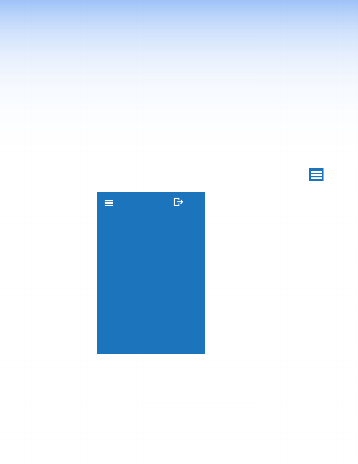
When the TLP Pro 300M is powered on, the currently loaded project is displayed. To access
the setup menu, press the Menu button (see figure 3, D, on page 6). There are six
available screens:
• Status
• Network
• Display
• Audio
• Project Information
• Advanced
To navigate between different screens, press the Menu icon in the top left corner.
The screen selection menu opens over the current screen, which is grayed out. The
menu has five buttons, corresponding to the five available screens:
Status EXIT
STATUS
NETWORK
DISPLAY
AUDIO
PROJECT INFORMATION
ADVANCED
Figure 5. Screen Selection Menu
Press the name of the screen you wish to open.
Press the Exit button in the top right corner of the screen to close the menu screens.
TLP Pro 300M • Setup Menu 9
Page 18

Status
This screen opens by default. To
access the Status screen from
any other part of the Setup menu,
press the Menu icon in the top left
corner and then press the Status
button.
Figure 6 shows the entire Status
screen. Because of size of the
touchscreen, you can only see part
of the Status screen at any time.
Scroll up or down within the screen
to navigate.
The Status screen is a read-only
screen that provides basic
information about the touchpanel.
Each section of the screen shows a
summary of the information on the
other screens. More information
about each topic can be found on
the Network, Display, Audio,
Project Information, and
Advanced screens. To navigate
to the appropriate screen, click the
arrow (>) next to the appropriate
heading. Alternatively, you can use
the Menu icon in the top left corner.
In the Network section, a
green circle with a white check
mark is shown next to the
IP address, when there is a
network connection. If there is no
connection, the circle is red with a
white cross.
In the Advanced section, the same
icons are used to show if a control
processor is connected or not.
Status EXIT
Device Information
Model
TLP Pro 300M
Part Number
60-1667-02
Firmware
1.00.0000-b010
Bootloader
1.00.0002
Network
IP Address
192.168.254.251
Hostname
TLP-Pro-300M-AB-CD-EF
DHCP
Off
Display
Resolution
320x480
Sleep Timer
119
Audio
Master Volume
80
Master Mute
Off
Project Information
System Project Name
N/A
GUI Project Name
N/A
Advanced
Primary Controller Address
192.168.254.250
System ID
6661
Storage
1 / 4313 MB
Figure 6. Status Screen
TLP Pro 300M • Setup Menu 10
Page 19

Network
kE
The image below shows the entire Network screen. Because of size of the touchscreen, you
can only see part of the screen at any time. Scroll up or down within the screen to navigate.
NOTE: The Cancel and Save buttons float so that they always appear at the bottom of
the screen, even when only the top part of the screen is displayed. They are used to
save changes to the network addresses or to cancel the changes without saving them.
NetworkEXIT
DHCP
Hostname
TLP-Pro-300M-AB-CD-EF
IP Address
192.168.254.251
Subnet Mask
255.255.255.0
Gateway
0.0.0.0
DNS Primary
127.0.0.1
Domain Name
extron.com
MAC Address
00-05-A6-AB-CD-EF
Cancel
Save
Networ
DHCP
Hostname
TLP-Pro-300M-AB-CD-EF
IP Address
192.168.254.251
Subnet Mask
255.255.255.0
Gateway
0.0.0.0
DNS Primary
127.0.0.1
Domain Name
extron.com
MAC Address
00-05-A6-AB-CD-EF
Cancel
XIT
Save
Figure 7.
Network Screen: DHCP on (left) and DHCP off (right)
The Domain Name and MAC Address are read-only.
1. If the IP addresses are assigned by DHCP, move the DHCP slider to the right, as shown in
figure 7 (left).
• When DHCP is on, the Host Name can be edited by pressing the right arrow (>).
There are no arrows next to the addresses and they cannot be edited because
they are set by the DHCP server.
• When DHCP is off, the arrow next to the Host Name disappears and it cannot be
edited. Arrows next to the IP Address, Subnet Mask, Gateway and DNS Primary
allow them to be edited.
If IP addresses are assigned manually, move the DHCP slider to the left, as shown in
figure 7 (right).
TLP Pro 300M • Setup Menu 11
Page 20
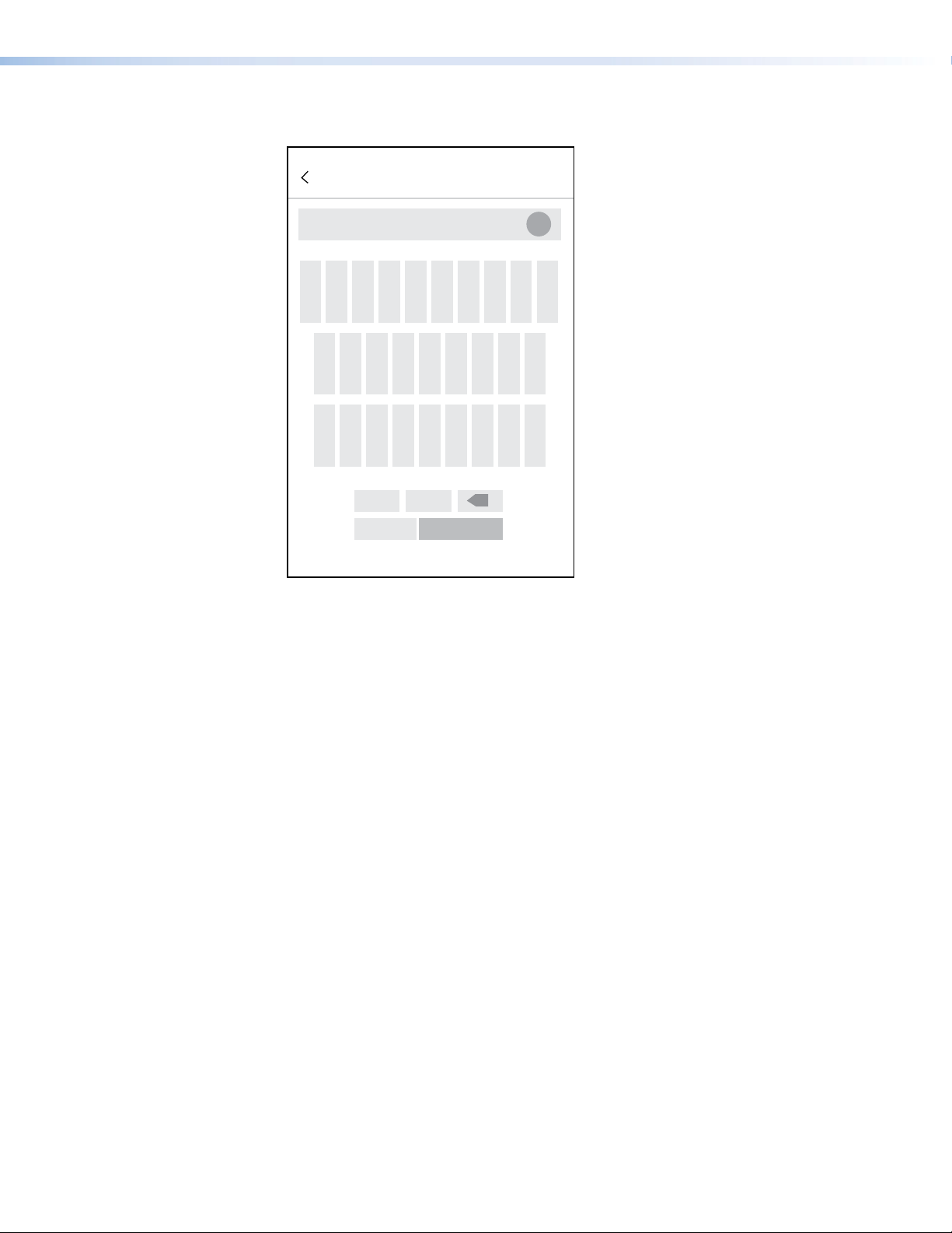
2. If DHCP is on, press the arrow next to the Host Name button to edit the host name. The
Host Name dialog box opens:
Hostname
TLP-Pro-300M-AB-CD-EF
X
qwer tyuiop
asdfgh jkl
zxcvbnm-
x
123 SUBMIT
Figure 8. Host Name Dialog Box
Use the keypad to enter a new name, which appears in the Host Name text box.
TLP Pro 300M • Setup Menu 12
Page 21

3. If DHCP is disabled, set the unit IP address, subnet mask, gateway address, and
56
89
DNS server address.
a. Press the arrow (>) next to the address that you are editing. The Address Dialog
Box opens:
IP Address
192.168.254.251
1
12 3
X
4
7
.
0
X
SUBMIT
Figure 9. Address Dialog Box
b. Enter the 3-digit value for an octet
NOTES:
• Octets can have any value between 0 and 255.
• If you attempt to enter an invalid number, for example 892, you are able
to enter the 89 but the 2 cannot be entered.
• After entering the value for an octet, you must enter a period (.) before
entering the value for the next octet.
c. Click Submit to save the changes, exit the dialog, and return to the Network screen.
Click the left arrow (<) in the heading to exit the dialog and return to the Network
screen without saving changes.
TLP Pro 300M • Setup Menu 13
Page 22
Display
01
01
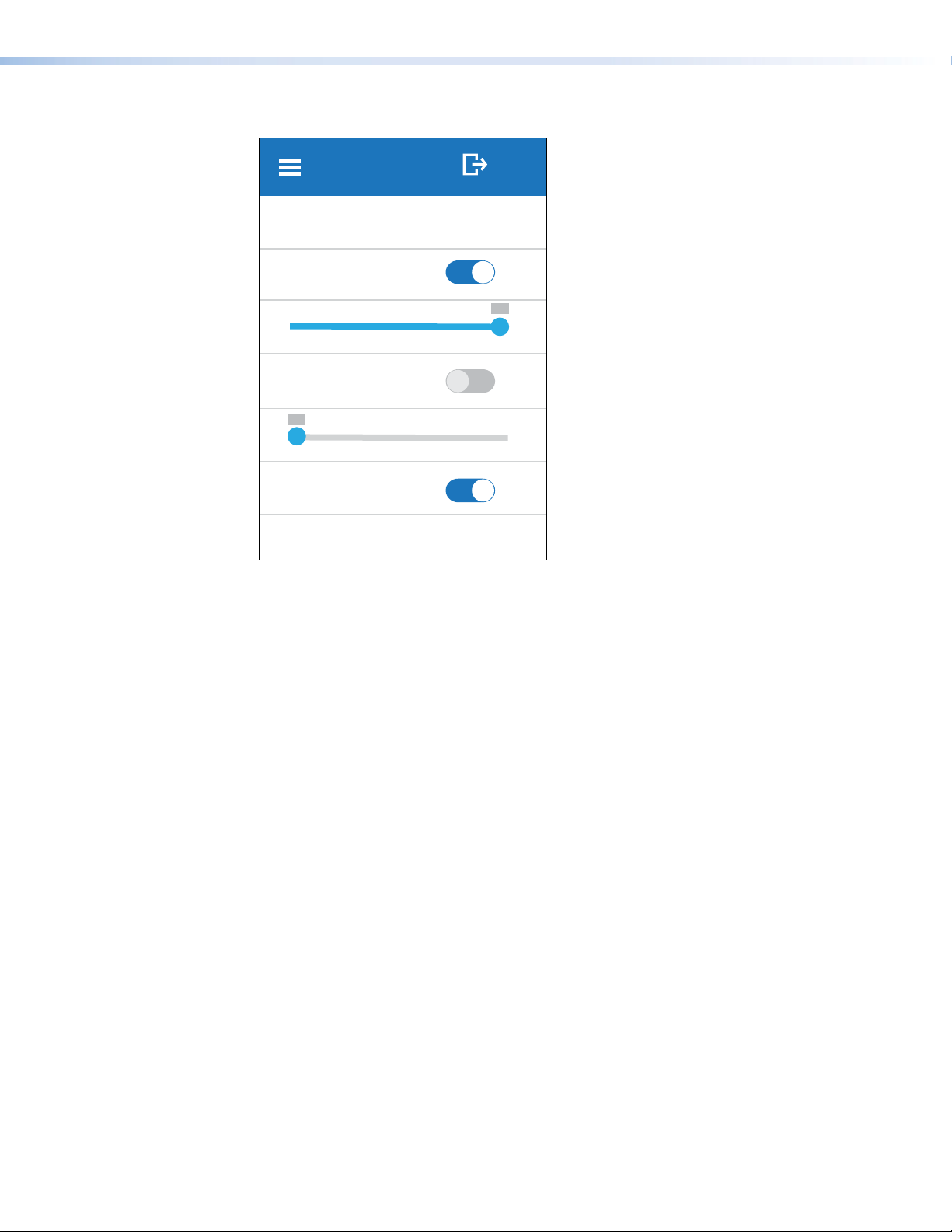
Display EXIT
Resolution 320x480
Sleep Timer
118
20
Auto Brightness
0
00
Wake On Motion
Figure 10. Display Screen
The Display screen allows you to set the Sleep Timer, Auto Brightness, and Wake on
Motion.
• Resolution (320x480) is read-only.
• Sleep Timer — determines how long the panel will be inactive before it enters sleep
mode. In sleep mode, the screen goes dark to save power.
Use the Sleep Timer switch to enable or disable the sleep timer. If the sleep timer is
enabled, use the slider to set a value between 1 and 120 minutes.
• Auto Brightness — provides a suitable amount of backlighting that is automatically
calculated from the amount of ambient light detected by the light detector.
• Screen Brightness — Use the slider to adjust the brightness setting between 0 and 100
manually. If screen brightness is changed using this slider, auto brightness is automatically
disabled.
• Wake on Motion — activates the panel from sleep mode when motion is detected near
the unit. Toggle between On and Off. If Wake on Motion is off, touch the screen to
activate the panel.
TLP Pro 300M • Setup Menu 14
Page 23

Audio
01
01
Mute on Mute off
Audio EXIT
Master
80
00
Click
80
0 100
Sound
80
00
Figure 11. Audio Screen
On the Audio screen, use the fader controls to adjust the Master, Click, and Sound volume
settings.
• Master volume sets the maximum volume for all the other sound volume settings. For
example, if the Master volume is set to 80 (80 percent of maximum), even when the
Sound volume is set to 100, it is equivalent to only 80 percent of maximum.
• Click sets the volume for audible feedback that accompanies events such as a screen
button being pressed.
• Sound sets the volume of audio from any audio file playback.
To mute any of the volume settings, press the corresponding loudspeaker icon to toggle
between mute off and mute on (see figure 12).
X
Figure 12. Mute On and Off Icons
TLP Pro 300M • Setup Menu 15
Page 24

Project Information
System Project
Name
GCPro Project.gcpro
Version
1.0.2.0
Creation Date
11/12/19 10:23:04 AM
Revision Date
01/18/20 12:30:00 PM
GUI Project
Name
Project1.gdl
Version
2.03.4.002
Creation Date
11/12/19 10:35:27 AM
Revision Date
01/18/20 12:41:51 PM
Resolution
320x480
Project Info EXIT
Figure 13. Project Information Screen
The Project Information screen is read-only. It provides information about the projects created
in Global Configurator Plus and Professional (System Project) and GUI Designer (GUI
Project).
TLP Pro 300M • Setup Menu 16
Page 25

Advanced
Advanced EXIT
System Info
Primary Controller Address
192.168.254.250
System ID
6661
Storage
Storage Used
1 MB
Storage Size
4313 MB
Menu PIN
Edit
Figure 14. Advanced Screen
The first two sections, System Info and Project Usage, provide read-only informaton.
System Info
Primary Controller Address — provides the IP address or hostname of the control
processor. If it is connected, a green circle with a white check mark is shown. If the control
processor is not connected, a red circle with a white X is shown.
System ID — is a four digit number generated by Global Scripter or Global Configurator
Plus and Professional and needed to link the touchpanel to a control processor. For more
information, see the Global Scripter Help File or Global Configurator Plus and Professional Help
File.
Storage
Storage Used — states the amount of storage used by the project.
Storage Size — states the total storage available on the touchpanel.
Menu PIN
To prevent unauthorized access to the setup menu, users can set a PIN, which is a 4-digit
number. Each digit can have any value from 0-9. The PIN setup options allow you to enable,
disable, or change the setup menu PIN.
By default, PIN use is disabled.
TLP Pro 300M • Setup Menu 17
Page 26

1. Set the PIN switch to on to enable PIN use. The Enter New PIN numeric keypad opens:
56
89
Enter New PIN
X
1
12 3
4
7
0
X
SUBMIT
Figure 15. Numeric Keypad for Setting PIN
2. Enter the PIN. The PIN is a 4-digit number. Each digit can have any value from 0-9. As the
digits are entered, four dots appear below the title.
3. When four digits have been entered, the Submit button is enabled. Press Submit to save
the PIN. The title bar changes to Confirm New Pin.
4. Enter the PIN a second time and press Submit. When the PIN entered on the second
occasion matches the PIN entered on the first occasion, the PIN is set and the dialog
closes.
To edit the PIN after it has been set, press Edit in the Advanced screen (see figure 14 on the
previous page) and enter the new PIN twice as described in steps 1-4 above.
To delete the PIN, set the Menu PIN to off (see the Advanced screen).
TLP Pro 300M • Setup Menu 18
Page 27

Configuration Software
This section of the user guide provides information about:
• Downloading and Installing Software
• Using the Software
• TLP Pro 300M Web Page
• Updating Firmware
Downloading and Installing Software
Toolbelt, GUI Designer, GlobalConfiguratorPlus and Professional, and Global Scripter can be
downloaded from www.extron.com.
NOTES:
• You will need an Extron Insider account to run Global Scripter, Global Configurator
Plus and Professional, or GUI Designer. To obtain one, contact the Extron Sales
Department.
• The TLP Pro 300M is not compatible with earler Extron software (GUI Configurator
or Globlal Configurator 3). Ensure you are downloading GUI Designer and Global
Configurator Plus and Professional.
Figure 16. Software Downloads from the Extron Website
1. Open www.extron.com and select the Download tab (
2. Click Software (
2
) .
TLP Pro 300M • Configuration Software 19
1
).
Page 28

The Download Center Software page opens:
Figure 17. Selecting Software to Download
3. The software may be shown in the panels at the top of the page. Figure 17 (
Global Configurator Plus and Professional.
You may need to use the left (<) or right (>) arrows (
is still not shown, click on the initial letter of the program in the alphabet menu (3).
) to find the software. If the software
2
) shows
1
Downloading software from the product page
Clicking on the panels at the top of the page takes you to the software product page on the
Extron website. Figure 18 shows the GCP product page.
Figure 18. GCP Product Page
To download and install the product, click Download (
The software is downloaded and installed on your PC. By default, the software is saved in a
newly created folder: C:\\Program Files (x86)\\Extron\<Software Name>.
TLP Pro 300M • Configuration Software 20
) and follow the onscreen instructions.
1
Page 29

Downloading software from the alphabet menu
Clicking on the initial letter of the software product (see figure 17, 3, on the previous page)
generates a list of software products with that initial letter.
Scroll down to the product you wish to download. Figure 19 shows the panel for Toolbelt.
Figure 19. Downloading from the Alphabet Menu
Click Learn More (
Click Release Notes (
release.
To download and install the product, click Download (
By default, the software is saved in a newly created folder: C:\\Program Files (x86)\\
Extron\<Software Name>.
Using the Software
Use the appropriate software help file for step-by-step instructions and more detailed
information. The Global Configurator Help File also includes an introduction to the software and
sections on how to start and configure a project.
Toolbelt
Use Toolbelt to provide device information, firmware updates, certificate management, and
configuration of network settings, system utilities (reset, reboot), and user management
(username and password) for TouchLink Pro devices.
) to go to the software product page.
1
) to find out what has been updated in the software since the previous
1
) and follow the onscreen instructions.
2
GUI Designer
Design the layout of the screen text and graphics using GUI Designer, which is a Windowsbased application. You can either customize one of several existing templates or create an
entirely new interface.
After the user interface has been designed, the project is saved, built, and imported into Global
Configurator Plus and Professional or Global Scripter.
Global Configurator Plus and Professional
Use Global Configurator Plus and Professional to assign functions to the screen text and
graphics.
After assigning the control functions, the project is rebuilt and uploaded to the control
processor and touchpanel.
Global Scripter
You can use Global Scripter as an alternative to GCP. Global Scripter provides an integrated
development environment for Extron control systems programming, including an Extronexclusive Python library (ControlScript) and Global Scripter modules to get you started. See the
GlobalScripter Help File for more information.
TLP Pro 300M • Configuration Software 21
Page 30

TLP Pro 300M Web Page
To access the touchpanel default Web pages, enter the IP address of the unit into the Web
browser of a PC connected to the same subnet. The sign-in screen opens:
Figure 20. TLP Pro 300M Sign-in Screen
Enter the Username (admin or user) and Password.
NOTES:
• The factory configured passwords for all accounts on this device have been set to the
device serial number. Passwords are case sensitive.
• If the device is reset to default settings, the password is the default password
configuration. The default password is extron.
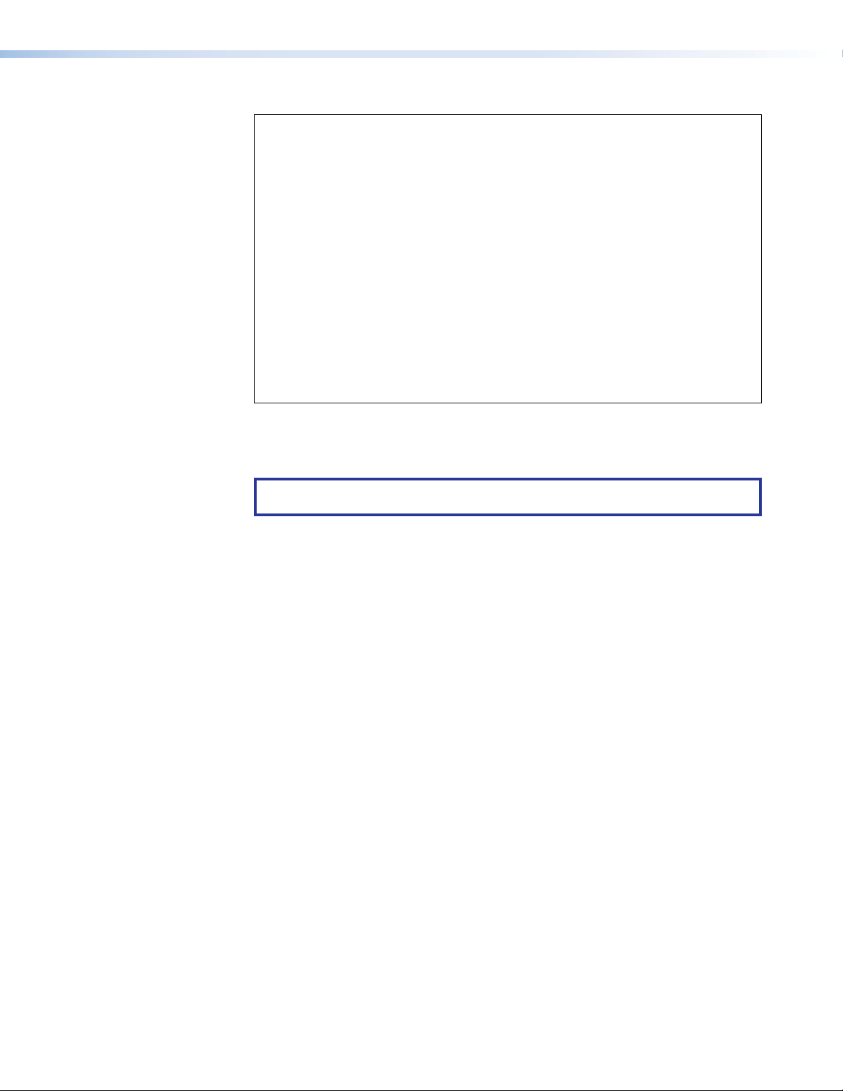
The default web page opens:
Figure 21. TLP Pro 300M Default Web Page
The single page provides general and network information about the unit. It is read-only and
cannot be used to configure the touchpanel network settings. This should be done using the
Setup Menu (see page 9) or Toolbelt (see the Toolbelt Help File).
TLP Pro 300M • Configuration Software 22
Page 31

You can use this page to upload firmware to the unit (see Updating Firmware Using the
Touchpanel Web Page on the next page).
Click License Information to view details about third-party packages and associated
licensing (and see the Pro Series Control Product Network Ports and Licenses Guide, which is
available at www.extron.com).
Updating Firmware
To update firmware, first download and run the file from the Extron website. Then use Toolbelt
or the TLP Pro 300M web page to upload the file to the touchpanel.
Downloading Firmware
The firmware must be downloaded to a PC on the same sub-network as the TLP Pro 300M.
1. On the Extron Website, click Download (
2. Click Firmware (
2
).
1
).
Figure 22. Firmware Download Center
TLP Pro 300M • Configuration Software 23
Page 32
The Download Firmware page opens:
Figure 23. Selecting Firmware to Download.
3. Click the letter T from the list of letters (
4. Scroll down the page until you find the firmware for the TLP Pro 300M.
NOTE: Your product will appear in this list only if a new version of the firmware has
been released since the product was first introduced.
1
).
5. (Optional) Click Release Notes (
6. Click Download (
7. Follow the on-screen instructions to download the program. An executable file is
downloaded to the PC.
8. Go to the Downloads folder and click on the file to install the firmware on the PC. By
default, it is stored at C:\\Program Files (x86)\Extron\Firmware\<product
name>\<firmware version>.
9. Use Toolbelt or the Touchpanel web page to upload this file to the touchpanel (see the
Toolbelt Help File or the following section).
3
).
) for more information about the firmware.
2
Updating Firmware Using the Touchpanel Web Page
1. If you have not already done so, download the firmware file to a computer on the same
network as the touchpanel (see the previous section).
2. Open the touchpanel Web page (see TLP Pro 300M Web Page on page 22).
Figure 24. Touchpanel Web Page: Firmware Uploader
3. Click Browse and navigate to the firmware location.
4. Click Upload. The firmware file is uploaded to the touchpanel. Follow the on-screen
instructions.
TLP Pro 300M • Configuration Software 24
Page 33

Mounting
The following instructions are provided for experienced installers to mount the TLP Pro 300M
touchpanel. The touchpanel can be wall-mounted, either using a standard 1-gang, UL-listed
electrical box (must be purchased separately), or directly into drywall or furniture. Suitable
mounting accessories can be found at www.extron.com.
ATTENTION:
• Do not install the TLP Pro 300M in a fire resistant rated wall or partition assembly.
• Ne pas installer le TLP Pro 300M dans un mur résistant au feu ou une cloison.
• All structural steps and electrical installation must be performed by qualified personnel
• Toute étape structurelle et installation électrique, doit être effectuée par un personnel
• Mounting With a UL-listed Electrical Box
• Mounting to Drywall or Furniture
in accordance with local and national building codes and electrical codes.
qualifié, conformément aux codes du bâtiment, aux codes incendie et sécurité, et aux
codes électriques, locaux et nationaux.
TLP Pro 300M • Mounting 25
Page 34
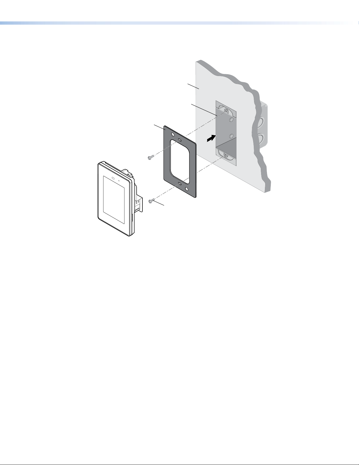
Mounting With a UL-listed Electrical Box
NORTH
AMERICA
NORTH
AMERICA
TLP Pr
The UL-listed electrical junction box must be purchased separately.
Wall
Electrical
Junction
Box
Metal
Mounting
Plate
o 300M
#6-32 x ¾"
pan-head screws
Figure 25. Mounting the TLP Pro 300M to a UL-listed Electrical Box
1. Cut a hole for the junction box at the required location.
2. If you are using the provided tether kit to deter theft, one loop of the tether kit should be
secured to a wall stud with a screw (not provided)
3. Run cables to the installation site as required.
4. Pass the other end of the tether kit and the cables through a knock-out in the junction
box.
5. Install the junction box by following the instructions provided by the manufacturer.
6. Secure the metal mounting plate to the junction box, using the #6-32 x ¾" pan-head
screws. Both the mounting plate and the screws are provided.
7. Attach cables to the back of the TLP Pro 300M (see TLP Pro 300M Rear Panel
Features on page 6).
8. If a tether kit is being used, loosen the security screw on the back panel (see figure 3,
, on page 6) just enough to insert the loop of the tether kit.
F
9. Tighten the screw to clamp the tether in place.
10. Attach the touchpanel to the metal mounting plate. The touchpanel is held in place by
magnets.
TLP Pro 300M • Mounting 26
Page 35

Mounting to Drywall or Furniture
NORTH
AMERICA
NORTH
AMERICA
TLP Pr
Toothed
2
Figure 26 shows how to mount the TLP Pro 300M in drywall. Follow the same procedure to
mount into furniture.
Metal
Mounting
Plate
o 300M
Wall
#6-32 x 1½"
flat-head screws
2
2
Clamping
Plate
111
Figure 26. Mounting the TLP Pro 300M to Drywall or Furniture
1. Download the TLP Pro 300M Cut-out Template from www.extron.com. Ensure that it is
printed at 100% size, with no scaling.
2. Remove the cut-out area from the template.
3. Attach the template to the wall in a suitable location, using a level to ensure the template is
aligned correctly.
4. Use the template to mark and remove the cut-out area (
screws that secure the toothed clamping plates.
) and drill two holes (2) for the
1
5. If you are using a tether kit to deter theft, one loop of the tether kit should be secured to a
wall stud.
6. Run cables to the installation site as required.
7. Secure the metal mounting plate to the clamping plates, using the #6-32 x 1½" flat-head
screws. The mounting plate, clamping plates, and screws are all provided.
As the screws turn they tighten the grip of the clamping plates on the inside surface of the
drywall.
8. Attach cables to the back of the TLP Pro 300M (see TLP Pro 300M Rear Panel
Features on page 6).
9. If a tether kit is being used, loosen the security screw on the back panel ((see figure 3,
, on page 6) just enough to insert the loop of the tether kit.
F
10. Tighten the screw to clamp the tether in place.
11. Attach the touchpanel to the metal mounting plate. The touchpanel is held in place by
magnets.
TLP Pro 300M • Mounting 27
Page 36

Reference Material
This section contains information about:
• Network Port Requirements
• Reset Modes
• Licensed Third-Party Software Used in the Touchpanels
Network Port Requirements and Licensed Third-party Software Used by the Touchpanels
For information about network port requirements and licensed third-party software for all the
touchpanels described in this guide, please refer to the Pro Series Control Product Network
Ports and Licenses Guide, which is available at www.extron.com.
Reset Modes
The TLP Pro 300M touchpanel has three reset modes that are initiated by pressing the Reset
button. An additional (fourth) mode toggles between enabling and disabling the DHCP client:
• Use Factory Firmware (see below)
• Reset All IP Settings (see the following page)
• Reset to Factory Defaults (see the following page)
• Enable or Disable the DHCP Client (see page 30)
The Reset button is found on the rear panel (see figure 3,
on page 6).
C
Use Factory Firmware
This mode is used to boot up the unit with factory-installed firmware for a single power cycle if
a firmware update fails or incompatibility issues arise with user-loaded firmware.
Activation
To start the Use Factory Firmware reset mode and replace firmware:
1. Remove power from the touchpanel.
2. On the touchpanel, hold down the recessed Reset button (see figure 3,
page 6) while applying power to the unit. When power is restored, the Reset LED (B)
lights. Hold the Reset button for a further two seconds before releasing it. The touchpanel
enters factory firmware mode.
3. Upload new firmware to the unit as desired (see Updating the Firmware on page 22).
NOTE: Do not continue to operate the touchpanel using the factory firmware version.
If you want to use the factory default firmware, you must upload that version again
(see Updating the Firmware).
, on
C
TLP Pro 300M • Reference Material 28
Page 37

Result
The unit reverts to factory-installed firmware. Event scripting does not start if the unit is
powered on in this mode. All user files and settings, adjustments, and IP settings are
maintained.
NOTE: To return the unit to the firmware version that was running prior to the reset, cycle
power to the unit.
Reset All IP Settings
This mode resets all IP settings to factory defaults.
Activation
To reset all IP settings:
1. Hold down the Reset button (see figure 3,
the Reset LED (B) blinks twice (once at 3 seconds, again at 6 seconds).
2. Release and press the Reset button momentarily (for <1 second) within 1 second.
Nothing happens if the momentary press does not occur within 1 second.
Result
• Sets the DHCP back to factory default (Off).
• Sets the Hostname back to factory default (TLP-Pro-300M-AB-CD-EF).
• Sets the IP address back to factory default (192.168.254.251).
• Sets the Subnet Mask address back to factory default (255.255.255.0).
• Sets the Gateway address back to the factory default (0.0.0.0).
• Sets the DNS Primary address back to the factory default (127.0.0.1).
• Sets the Domain name back to factory default (Blank).
, on page 6) for about 6 seconds until
C
Reset to Factory Defaults
This mode resets all IP settings and touchpanel settings, including passwords, to factory
defaults and removes all configurations. It allows you to start over with configuration and
uploading.
NOTES:
• The factory configured passwords for all accounts on this device have been set to the
device serial number. Passwords can be changed during configuration. Passwords
are case sensitive.
• If the device is reset to default settings, the password is the default password
configuration. The default password is extron (for either admin or user accounts).
Activation
To reset the unit to all factory default settings:
1. Hold down the Reset button for about 9 seconds until the Reset LED blinks three times
(once at 3 seconds, again at 6 seconds, again at 9 seconds).
2. Release and press the Reset button momentarily (for <1 second) within 1 second.
Nothing happens if the momentary press does not occur within 1 second.
Result
Reset to Factory Defaults mode performs a complete reset to factory defaults (except the
firmware).
• Does everything Reset All IP Settings mode does.
• Removes touchpanel user interface layout and configurations.
• Resets all touchpanel settings to factory default.
TLP Pro 300M • Reference Material 29
Page 38

Enable or Disable the DHCP Client
This mode toggles between DHCP enabled and DHCP disabled. This can also be carried out
from the Network screen of the Setup Menu (see page 9).
Activation
To enable or disable the DHCP client for the LAN port:
1. Press the Reset button five times (consecutively).
2. Release the button. Do not press the button within 3 seconds, following the fifth press.
Result
If DHCP was enabled, it is now disabled. The Reset LED blinks three times.
If DHCP was disabled, it is now enabled. The Reset LED blinks six times.
NOTES:
• By default DHCP is off and the unit uses a static IP address.
• When you disable DHCP, the unit reverts to using the previously-set static IP address.
Secure Sockets Layer (SSL) Certificates
Extron TouchLink Pro products ship with factory-installed SSL certificates created by Extron.
If you want or are required to use a different SSL certificate at your installation site, then you
can use system utilities in the Toolbelt software to change the SSL certificate at any time. The
Toolbelt Help File provides instructions on how to apply an SSL certificate.
NOTES:
• You must run Toolbelt as an administrator.
• Some certificates require a passphrase that is created when the certificate is created.
If a passphrase is required, you must enter that passphrase before uploading and
applying the certificate.
These devices support standard OpenSSL certificate encodings such as .pem (Privacyenhanced Electronic Mail) and .der (Distinguished Encoding Rules) file types. PEM file types are
ASCII encoded and are the required format for uploading to the Extron control product. DER
file types are binary encoded and can typically have several file extension variations, such as
.crt and .cer. There are many standard tools that can convert from DER to PEM file encodings
if needed.
NOTE: A DER format file must be converted to PEM encoding before uploading it to the
button panel, control processor, or collaboration receiver.
To properly create the certificate for uploading to Extron control devices, ensure that the
certificate file meets the following requirements:
• contains X.509 certificate information
• contains public and private keys
• uses PEM encoding
NOTE: ITU-T standard X.509 covers aspects of public key encryption, digital
cryptography, certificates, and validation.
Contact your IT administrator for more information on what tools and policies are required to
obtain or create the SSL certificate and, if necessary, the corresponding passphrase.
TLP Pro 300M • Reference Material 30
Page 39

IEEE 802.1X Certificates
IEEE 802.1X is a standard that enables port-based network access control via an
authentication server. The protocol requires that all devices must be authenticated before
gaining privileges to access the secure part of the network.
The Extron implementation of 802.1X supports PEAP - MSCHAPV2 and EAP - TLS methods
of authentication. This section of the guide details the Certificate File Requirements and the
Private Key File Requirements to be used in the system.
Extron provides resources for learning about 802.1X implementation:
• The Extron 802.1X Technology Reference Guide, available from www.extron.com, is the
primary resource for background information, system planning, topology, and how to set
up these systems.
• The Toolbelt Help file provides detailed step-by-step information on using the software to
set up 802.1X for IP Link Pro control systems and on troubleshooting.
• The 802.1X Primer white paper, also available from www.extron.com, provides a general
overview of the protocol and its use within a control system.
NOTES:
• You must run Toolbelt as an administrator.
• Machine certificates require a private key file, which can be encrypted.
Certificate File Requirements
PEM (Privacy-enhanced Electronic Mail) file types are ASCII encoded, and they are the required
format for 802.1X authentication for the TouchLink Pro control systems. DER (Distinguished
Encoding Rules) file types are binary encoded and can typically have several file extension
variations, such as .crt and .cer.
NOTE: DER encoded files (files with .der, .crt, or .cer extensions that are encoded in DER
binary format) must be converted to a PEM encoded file type (.pem) before being used
for authentication.
DER encoded certificates must be converted to PEM encoding using a third-party tool.
Contact your IT administrator for more information on required tools.
To create the 802.1X security certificate for uploading to Extron TouchLink Pro control systems,
ensure that the certificate file meets the following requirements:
• It contains X.509 certificate information.
• It contains a private key (for machine certificates only).
• It is PEM encoded.
• It has a file extension that is .crt or .pem
• Its file name consists of the following types of valid characters:
• Alphanumerical (A-Z, a-z, 0-9) characters
• Some special characters (colon [:], underscore [_], and hyphen [-])
NOTE: Spaces are not permitted anywhere in the name.
Private Key File Requirements
Private key files are required only when employing machine certificates. Follow these
requirements for creating a private key:
• Its file name consists of the following types of valid characters:
• Alphanumerical (A-Z, a-z, 0-9) characters
• Some special characters (colon [:], underscore [_], and hyphen [-])
• It has a file extension that is .key or .pem.
• It can have optional encryption (via password or passphrase).
TLP Pro 300M • Reference Material 31
Page 40

Extron Warranty
Extron Electronics warrants this product against defects in materials and workmanship for a period of three years
from the date of purchase. In the event of malfunction during the warranty period attributable directly to faulty
workmanship and/or materials, Extron Electronics will, at its option, repair or replace said products or components,
to whatever extent it shall deem necessary to restore said product to proper operating condition, provided that it is
returned within the warranty period, with proof of purchase and description of malfunction to:
USA, Canada, South America,
and Central America:
Extron Electronics
1230 South Lewis Street
Anaheim, CA 92805
U.S.A.
Europe:
Extron Europe
Hanzeboulevard 10
3825 PH Amersfoort
The Netherlands
Africa:
Extron South Africa
South Tower
160 Jan Smuts Avenue
Rosebank 2196, South Africa
This Limited Warranty does not apply if the fault has been caused by misuse, improper handling care, electrical
or mechanical abuse, abnormal operating conditions, or if modifications were made to the product that were not
authorized by Extron.
Asia:
Extron Electronics Asia Pte. Ltd.
135 Joo Seng Road, #04-01
PM Industrial Bldg.
Singapore 368363
Singapore
China:
Extron China
686 Ronghua Road
Songjiang District
Shanghai 201611
China
Japan:
Extron Electronics, Japan
Kyodo Building, 16 Ichibancho
Chiyoda-ku, Tokyo 102-0082
Japan
Middle East:
Extron Middle East
Dubai Airport Free Zone
F13, PO Box 293666
Dubai, United Arab Emirates
NOTE: If a product is defective, please call Extron and ask for an Application Engineer to receive an RA (Return
Authorization) number. This will begin the repair process.
USA: 714.491.1500 or 800.633.9876 Asia: 65.6383.4400
Europe: 31.33.453.4040 or 800.3987.6673 Japan: 81.3.3511.7655
Africa: 27.11.447.6162 Middle East: 971.4.299.1800
Units must be returned insured, with shipping charges prepaid. If not insured, you assume the risk of loss or damage
during shipment. Returned units must include the serial number and a description of the problem, as well as the
name of the person to contact in case there are any questions.
Extron Electronics makes no further warranties either expressed or implied with respect to the product and its quality,
performance, merchantability, or fitness for any particular use. In no event will Extron Electronics be liable for direct,
indirect, or consequential damages resulting from any defect in this product even if Extron Electronics has been
advised of such damage.
Please note that laws vary from state to state and country to country, and that some provisions of this warranty may
not apply to you.
Worldwide Headquarters: Extron USA West, 1025 E. Ball Road, Anaheim, CA 92805, 800.633.9876
 Loading...