

Page 1

TouchLink Pro Touchpanels
TLP Pro 1225, 1525,
and 1725 Series
TouchLink Pro Touchpanel Control Systems
User Guide
68-3474-01 Rev. A
09 20
Page 2
Safety Instructions
Safety Instructions • English
Istruzioni di sicurezza • Italiano
WARNING: This symbol, , when used on the product, is intended to
alert the user of the presence of uninsulated dangerous voltage within the
product’s enclosure that may present a risk of electric shock.
ATTENTION: This symbol, , when used on the product, is intended
to alert the user of important operating and maintenance (servicing)
instructions in the literature provided with the equipment.
For information on safety guidelines, regulatory compliances, EMI/EMF
compatibility, accessibility, and related topics, see the Extron Safety and
Regulatory Compliance Guide, part number 68-290-01, on the Extron website,
www.extron.com.
Sicherheitsanweisungen • Deutsch
WARUNG: Dieses Symbol auf demProdukt soll den Benutzer darauf
aufmerksam machen, dass im Inneren des Gehäuses dieses Produktes
gefährliche Spannungen herrschen, die nicht isoliert sind und die einen
elektrischen Schlag verursachen können.
VORSICHT: Dieses Symbol auf dem Produkt soll dem Benutzer in der
im Lieferumfang enthaltenen Dokumentation besonders wichtige Hinweise
zur Bedienung und Wartung (Instandhaltung) geben.
Weitere Informationen über die Sicherheitsrichtlinien, Produkthandhabung,
EMI/EMF-Kompatibilität, Zugänglichkeit und verwandte Themen finden Sie in den
Extron-Richtlinien für Sicherheit und Handhabung (Artikelnummer
68-290-01) auf der Extron-Website, www.extron.com.
AVVERTENZA: Il simbolo, , se usato sul prodotto, serve ad avvertire
l’utente della presenza di tensione non isolata pericolosa all’interno del
contenitore del prodotto che può costituire un rischio di scosse elettriche.
ATTENTZIONE: Il simbolo, , se usato sul prodotto, serve
ad avvertire l’utente della presenza di importanti istruzioni di funzionamento
e manutenzione nella documentazione fornita con l’apparecchio.
Per informazioni su parametri di sicurezza, conformità alle normative,
compatibilità EMI/EMF, accessibilità e argomenti simili, fare riferimento alla Guida
alla conformità normativa e di sicurezza di Extron, cod. articolo 68-290-01, sul
sito web di Extron,
Instrukcje bezpieczeństwa • Polska
OSTRZEŻENIE: Ten symbol, , gdy używany na produkt, ma na celu
poinformować użytkownika o obecności izolowanego i niebezpiecznego
napięcia wewnątrz obudowy produktu, który może stanowić zagrożenie
porażenia prądem elektrycznym.
UWAGI: Ten symbol, , gdy używany na produkt, jest przeznaczony do
ostrzegania użytkownika ważne operacyjne oraz instrukcje konserwacji
(obsługi) w literaturze, wyposażone w sprzęt.
Informacji na temat wytycznych w sprawie bezpieczeństwa, regulacji wzajemnej
zgodności, zgodność EMI/EMF, dostępności i Tematy pokrewne, zobacz Extron
bezpieczeństwa i regulacyjnego zgodności przewodnik, część numer 68-290-01,
na stronie internetowej Extron,
www.extron.com.
www.extron.com.
Instrucciones de seguridad • Español
ADVERTENCIA: Este símbolo, , cuando se utiliza en el producto, avisa al
usuario de la presencia de voltaje peligroso sin aislar dentro del producto,
lo que puede representar un riesgo de descarga eléctrica.
ATENCIÓN: Este símbolo, , cuando se utiliza en el producto,
avisa al usuario de la presencia de importantes instrucciones de uso y
mantenimiento estas estan incluidas en la documentación proporcionada
con el equipo
Para obtener información sobre directrices de seguridad, cumplimiento
de normativas, compatibilidad electromagnética, accesibilidad y temas
relacionados, consulte la Guía de cumplimiento de normativas y seguridad de
Extron, referencia 68-290-01, en el sitio Web de Extron, www.extron.com.
.
Instructions de sécurité • Français
AVERTISSEMENT : Ce pictogramme, , lorsqu’il est utilisé sur le
produit, signale à l’utilisateur la présence à l’intérieur du boîtier du produit
d’une tension électrique dangereuse susceptible de provoquer un choc
électrique.
ATTENTION : Ce pictogramme, , lorsqu’il est utilisé sur le produit,
signale à l’utilisateur des instructions d’utilisation ou de maintenance
importantes qui se trouvent dans la documentation fournie avec
l’équipement.
Pour en savoir plus sur les règles de sécurité, la conformité à la réglementation,
la compatibilité EMI/EMF, l’accessibilité, et autres sujets connexes, lisez les
informations de sécurité et de conformité Extron, réf. 68-290-01, sur le site
Extron, www.extron.com.
Инструкция по технике безопасности • Русский
ПРЕДУПРЕЖДЕНИЕ: Данный символ, , если указан
на продукте, предупреждает пользователя о наличии
неизолированного опасного напряжения внутри корпуса
продукта, которое может привести к поражению электрическим
током.
ВНИМАНИЕ: Данный символ, , если указан на продукте,
предупреждает пользователя о наличии важных инструкций по
эксплуатации и обслуживанию в руководстве, прилагаемом к
данному оборудованию.
Для получения информации о правилах техники безопасности,
соблюдении нормативных требований, электромагнитной
совместимости (ЭМП/ЭДС), возможности доступа и других вопросах
см. руководство по безопасности и соблюдению нормативных
требований Extron на сайте Extron: , www.extron.com,
номер по каталогу - 68-290-01.
安全说明 • 简体中文
警告: 产品上的这个标志意在警告用户, 该产品机壳内有暴露的危险
电 压 ,有 触 电 危 险 。
注意: 产品上的这个标志意在提示用户, 设备随附的用户手册中有重
要的操作和维护(维修)说明。
关于我们产品的安全指南、遵循的规范、EMI/EMF 的兼容性、无障碍使
用的特性等相关内容,敬请访问 Extron 网站 , www.extron.com,参见 Extron
安全规范指南,产品编号 68-290-01
。
Page 3
安全記事 • 繁體中文
안전 지침 • 한국어
警告: 若產品上使用此符 號,是為了提醒使 用者,產品機殼內存在未隔離的危險
電壓,可能會導致觸電之風險。
注意 若產品上使用此符號,是為了提醒使用者,設備隨附的用戶手冊中有重要
的 操 作 和 維 護( 維 修 )説 明 。
有關安全性指導方針、法規遵守、EMI/EMF 相容性、存取範圍和相關主題的詳細資訊,
請瀏覽 Extron 網站:www.extron.com,然後參閱《Extron 安全性與法規遵守手
冊》,準則編號 68-290-01。
경고: 이 기호 가 제품에 사용될 경우, 제품의 인클로저 내에 있는
접지되지 않은 위험한 전류로 인해 사용자가 감전될 위험이 있음을
경고합니다.
주의: 이 기호 가 제품에 사용될 경우, 장비와 함께 제공된 책자에 나와
있는 주요 운영 및 유지보수(정비) 지침을 경고합니다.
안전 가이드라인, 규제 준수, EMI/EMF 호환성, 접근성, 그리고 관련 항목에 대한
자세한 내용은 Extron 웹 사이트(www.extron.com)의 Extron 안전 및 규제 준수
안내서, 68-290-01 조항을 참조하십시오.
Copyright
© 2020 Extron. All rights reserved.
Trademarks
All trademarks mentioned in this guide are the properties of their respective owners.
The following registered trademarks®, registered service marks(SM), and trademarks(™) are the property of RGBSystems, Inc. or Extron (see the
current list of trademarks on the Terms of Use page at www.extron.com):
Registered Trademarks
(®)
Cable Cubby, ControlScript, CrossPoint, DTP, eBUS, EDID Manager, EDID Minder, Extron, eLink, Flat Field, FlexOS, Glitch Free,
Global Configurator, Global Scripter, GlobalViewer, Hideaway, HyperLane, IP Intercom, IP Link, Key Minder, LinkLicense, LockIt, MediaLink,
MediaPort, NAV, NetPA, PlenumVault, PoleVault, PowerCage, PURE3, Quantum, ShareLink, Show Me, SoundField, SpeedMount, SpeedSwitch,
StudioStation, System INTEGRATOR, TeamWork, TouchLink, V-Lock, VideoLounge, VN-Matrix, VoiceLift, WallVault, WindoWall, XPA, XTP, XTP
Systems, and ZipClip.
(SM)
Registered Service Mark
: S3 Service Support Solutions
Trademarks
(™)
AAP, AFL (Accu-RATE Frame Lock), ADSP (Advanced Digital Sync Processing), Auto-Image, AVEdge, CableCover, CDRS (Class D
Ripple Suppression), Codec Connect, DDSP (Digital Display Sync Processing), DMI (Dynamic Motion Interpolation), Driver Configurator,
DSP Configurator, DSVP (Digital Sync Validation Processing), EQIP, Everlast, FastBite, Flex55, FOX, FOXBOX, IP Intercom HelpDesk, MAAP,
MicroDigital, Opti-Torque, PendantConnect, ProDSP, QS-FPC (QuickSwitch Front Panel Controller), Room Agent, Scope-Trigger, SIS,
Simple Instruction Set, Skew-Free, SpeedNav, Triple-Action Switching, True4K, True8K, Vector™ 4K, WebShare, XTRA, and ZipCaddy
Page 4
FCC Class A Notice
This equipment has been tested and found to comply with the limits for a Class A digital
device, pursuant to part15 of the FCC rules. The ClassA limits provide reasonable protection
against harmful interference when the equipment is operated in a commercial environment.
This equipment generates, uses, and can radiate radio frequency energy and, if not installed
and used in accordance with the instruction manual, may cause harmful interference to radio
communications. Operation of this equipment in a residential area is likely to cause interference.
This interference must be corrected at the expense of the user.
NOTES:
• This unit was tested with shielded I/O cables on the peripheral devices. Shielded
• For more information on safety guidelines, regulatory compliances, EMI/EMF
Battery Notice
This product contains a battery. Do not open the unit to replace the battery. If the
battery needs replacing, return the entire unit to Extron (for the correct address, see the Extron
Warranty section on the last page of this guide).
CAUTION: Risk of explosion if battery is replaced by an incorrect type. Dispose of used
ATTENTION : Risque d’explosion. Ne pas remplacer la pile par le mauvais type de pile.
cables must be used to ensure compliance with FCC emissions limits.
compatibility, accessibility, and related topics, see the Extron Safety and Regulatory
Compliance Guide on the Extron website.
batteries according to the instructions.
Débarrassez-vous des piles utilisées selon le mode d’emploi.
Page 5
Conventions Used in this Guide
Notifications
In this user guide, the following are used:
WARNING: Potential risk of severe injury or death.
AVERTISSEMENT : Risque potentiel de blessure grave ou de mort.
CAUTION: Risk of minor personal injury.
ATTENTION : Risque de blessuremineure.
ATTENTION:
•
Risk of property damage.
• Risque de dommages matériels.
NOTE: A note draws attention to important information.
Software Commands
NOTE: For commands and examples of computer or device responses mentioned in this
guide, the character “0” is used for the number zero and “O” represents the capital letter
“o”.
Directory paths that do not have variables are written in the font shown here:
Reply from 208.132.180.48: bytes=32 times=2ms TTL=32
C:\Program Files\Extron
Variables are written in slanted form as shown here:
ping xxx.xxx.xxx.xxx —t
SOH R Data STX Command ETB ETX
Selectable items, such as menu names, menu options, buttons, tabs, and field names are written
in the font shown here:
From the
Click the
File menu, select New.
OK button.
Specifications Availability
Product specifications are available on the Extron website, www.extron.com.
Extron Glossary of Terms
A glossary of terms is available at www.extron.com/technology/glossary.aspx.
Page 6

Page 7

Contents
Introduction............................................................ 1
About the TLP Pro 1225, 1525, and 1725 Series ....1
Features ..................................................................1
Application Diagram ................................................ 3
Requirements ..........................................................3
Software .............................................................3
Hardware ............................................................3
Installation Overview ........................................... 4
Panel Features ...................................................... 6
TLP Pro 1225, 1525, and 1725 Series
Front Panel Features ..............................................6
TLP Pro 1225, 1525, and 1725 Series
Rear Panel Features ...............................................8
Connecting Power ................................................11
12 VDC Power Supply ......................................11
Power over Ethernet .........................................11
Routing Cables (TG Models) .................................. 13
Setup Menu .......................................................... 14
Setup Menu ..........................................................14
Status Screen ...................................................15
Network Screen ................................................15
Display Screen ..................................................17
Audio Screen ....................................................18
Input Screen .....................................................18
Advanced Screen..............................................20
Configuration Software ..................................... 21
Configuration Software ..........................................21
Install Software ......................................................21
Using the Software ................................................23
TLP Pro 1225, 1525, and 1725 Series
Web Page ............................................................24
Updating the Firmware ..........................................25
Downloading Firmware ......................................25
Updating Firmware Using the Touchpanel
Web Page ........................................................26
Updating Firmware Using Toolbelt ..................... 26
Mounting ............................................................... 27
Mounting the TLP Pro 1225MG, 1525MG, and
1725MG ..............................................................27
Rack Mounting ..................................................27
Wall Mounting ...................................................28
Mounting the TLP Pro 1225TG, 1525TG, and
1725TG ...............................................................31
Removing the Rear and Base Covers ................ 31
Desktop Mounting ............................................31
VESA Mounting ................................................. 32
Reference Material ............................................. 33
Best Practices for Cleaning Your
Extron Products ...................................................33
Network Port Requirements and Licensed
Third-Party Software Used by the Touchpanels .... 33
Reset Modes.........................................................34
Use Factory Firmware .......................................34
Reset All IP Settings .......................................... 34
Reset to Factory Defaults .................................. 35
Enable or Disable the DHCP Client .................... 35
Secure Sockets Layer (SSL) Certificates ................36
IEEE 802.1X Certificates ........................................36
Certificate File Requirements .............................37
Private Key File Requirements ...........................37
TLP Pro 1225, 1525, and 1725 Series • Contents vii
Page 8

TLP Pro 1225, 1525, and 1725 Series • Contents viii
Page 9

Introduction
This guide describes the function, installation, and operation of the following Extron Touchlink Pro
Touchpanels:
• TLP Pro 1225MG • TLPPro1225TG
• TLP Pro 1525MG • TLPPro1525TG
• TLP Pro 1725MG • TLPPro1725TG
Unless otherwise stated, the terms “touchpanel” or “TLP Pro” refer to any of the six models.
The touchpanels are ideal for any AV applications requiring large touchpanels with flexible
mounting options and fully customizable interfaces.
This section covers the following topics:
• About the TLP Pro 1225, 1525, and 1725 Series
• Features
• Application Diagram
• Requirements
About the TLP Pro 1225, 1525, and 1725 Series
The TLP Pro 1225 Series touchpanels have 12.1 inch screens with a resolution of 1280x800.
The TLP Pro 1525 Series touchpanels have 15.6 inch screens with a resolution of 1366x768.
The TLP Pro 1725 Series touchpanels have 17.3 inch screens with a resolution of 1920x1080.
The MG models (TLP Pro 1225MG, TLP Pro 1525MG, and TLP Pro 1725MG) are
wall-mountable. The TG models (TLP Pro 1225TG, TLP Pro 1525TG, and TLP Pro 1725TG) have
a weighted base that can be tilted, which allows them to stand on any suitable table or desktop.
A range of mounting options are available for all the models (see Mounting on page 27).
The screen layout is designed with the Extron GUI Designer software. The functions are assigned
to the screen objects with the Extron Global Configurator Plus and Professional or Global Scripter
software. This provides versatility and adaptability to the configuration and control of an AV
system.
A motion sensor, a light sensor, and a speaker provide sleep mode, auto dimming, and audible
feedback.
Features
• Capacitive touchscreen with 16 million colors — Vibrant, edge-to-edge glass display
with a more responsive control surface
• Ultra-fast quad-core processor — For quick page loads.
• Full motion video preview and monitoring — With HDMI and XTP inputs
• Compatible with the full range of Extron IP Link Pro control processors and HC 400
Series systems — Allows easy integration into existing systems
• Power over Ethernet — The touchpanel is powered directly by a PoE+ switch or injector,
eliminating the need for bulky local power supplies.
• Built-in speakers provide stereo audio — For video preview and audible feedback from
button presses.
TLP Pro 1225, 1525, and 1725 Series • Introduction 1
Page 10

• 3.5 mm headphone jack — Provides local audio out from the touchpanel.
• Light sensor — Adjusts screen brightness as the ambient room lighting changes.
• Configurable red and green status lights —Indicate the availability or call status of a
room.
• Two high speed USB 2.0 ports — For future expansion
• Automatic clock synchronization — Allows touchpanel to display the accurate time and
date.
• Energy-saving features —
• Adjustable sleep timer puts touchpanel into sleep mode
• Motion detector wakes touchpanel
• Mounting options for tilt models (TG models):
• Sit on a tabletop — weighted base allows up to 40° of tilt.
• Threaded holes in baseplate allow for secure mounting to a table.
• Kensington
®
lock support allows the touchpanels to be locked to a table or other flat
surface.
• Supports the optional SMA-1 Swivel Mount Adapter.
• VESA FDMI Type D 100 mm mounting pattern standard can be used for VESA
mounting.
• Mounting options for wall-mount models (MG models):
• Mount on a wall, lectern, or any flat surface. The included mounting hardware enables
multiple mounting options.
• The optional back box, BB 700M can be used where local codes require a rear metal
enclosure.
• Fully customizable using Extron control system software — GUI Designer combined
with Global Configurator Plus, Global Configurator Professional, or Global Scripter.
• Supports the Extron Control App.
• Manage, monitor, and control this device remotely — Using GVE - GlobalViewer
Enterprise Resource Management software
TLP Pro 1225, 1525, and 1725 Series • Introduction 2
Page 11

Application Diagram
Power Sequencer
The application diagram below shows the TLP Pro 1225MG. The other touchpanels described in
this user guide can be used in similar configurations.
HDMI
PC
Extron
TLP Pro 1225MG
12" Wall Mount
TouchLink Pro
Touchpanel
HDMI
Requirements
Software
RS-232
REMOTE
RS-232
Extron
DA2 HD 4K
TxRx G
Distribution Amplier
COM 1
G
Tx Rx RTSCTS
POWER
12V
1A MAX
VOL
VCG
RELAYS
COM 2
Tx Rx
1 2C
G
DIGITAL I/O
1 23 4 G
eBUS
+V +S-SG
PWR OUT =6W
Ethernet
IPCPPRO 250 xi
IR/S
GS
LAN
IR
Extron
OCS 100W
Occupancy Sensor
Ethernet/PoE+
Extron
IPCP Pro 250 xi
IP Link Pro
Control Processor
IR Emitter
4K Media Player
ABCDEF
POWER
12V
--A MAX
12
INPUT
HDMI
MODEL 80
Flat Panel Display
OUTPUTS
FLAT PANEL
Figure 1. Application Diagram
For a complete list of the requirements for running GUI Designer, Global Configurator Plus and
Professional, Global Scripter, and Toolbelt see the Extron web page for that software.
Hardware
NOTE: These touchpanels are not compatible with GlobalConfigurator 3 or
GUIConfigurator.
An Extron IP Link Pro control interface must also be connected to the same network domain as
the TouchLink panel. See www.extron.com for a list of suitable controllers.
NOTE: These touchpanels are not compatible with Extron IP Link (non-Pro) controllers.
TLP Pro 1225, 1525, and 1725 Series • Introduction 3
Page 12

Installation Overview
This section contains an overview of the installation process. Follow the links for a more detailed
explanation of each step.
1. Before starting, download and install the latest versions of the following software:
GUI Designer — For designing layouts for Extron TouchLink Pro touchpanels and third
party touch interfaces.
Global Configurator Plus and Professional — For setting up and configuring the
control processor and touchpanel.
Global Scripter — Provides an integrated development environment for Extron control
systems programming.
Toolbelt — Provides device discovery, device information, firmware updates,
and configuration of network settings, system utilities, and user management for
TouchLink Pro devices.
For more information, see Using the Software on page 23 or see the Extron web page
for the software.
2. Obtain the following network information from your network administrator:
Dynamic Host Configuration Protocol (DHCP) status (on or off). If DHCP is off, you
will also require:
IP address
Subnet mask
Gateway
Username — This can be either admin or user.
Password — The factory configured passwords for all accounts on this device have
been set to the device serial number. Passwords can be changed during configuration.
Passwords are case sensitive.
NOTE: If the device is reset to default settings, the password is the default
password configuration. The default password is extron (for either admin or
user accounts).
MAC address — Make a note of the touchpanel MAC address, which can be found on
the rear panel label (you need to remove the rear cover for TG models).
SSL security certificates and IEEE 802.1X authentication — Extron touchpanels
come with a factory-installed Secure Sockets Layer (SSL) security certificate. IEEE
802.1X authentication is also supported once enabled. See Secure Sockets Layer
(SSL) Certificates on page 36 or IEEE 802.1X Certificates on page 36 for more
information.
TLP Pro 1225, 1525, and 1725 Series • Installation Overview 4
Page 13

3. Mount and cable the units:
ATTENTION:
• Do not power on the touchpanels or control processors until you have read the
Attention notice on page 12.
• Ne branchez pas les écrans tactiles ou les contrôleurs avant d’avoir lu les mises en
garde page 12.
Mount the units. There are several mounting options for TouchLink Pro touchpanels (see
Mounting on page 27).
NOTE: If you use the setup menu to configure the wall-mount models, do not
mount the unit before configuring them as you need access to the rear panel
Menu button.
Connect cables to the touchpanels (see TLP Pro 1225, 1525, and 1725 Series Rear
Panel Features on page 8).
Connect the power cords and power on all devices (see XTP/LAN/PoE input on
page 10 or Power supply input on page 9).
NOTES:
• The TLP Pro 1225MG, 1525MG, and 1725MG models must be powered by
Power over Ethernet.
• The TLP Pro 1225TG, 1525TG, and 1725TG models have the option to be
powered by a 12 VDC power supply or Power over Ethernet.
• The TLP Pro 1725MG and TLP Pro 1725TG are shipped with an Extron
PI 140 power injector supplied. For the other models a suitable power source
must be purchased separately.
4. Set up the touchpanels for network communication:
Connect the PC that you are using for setup, the control processor, and the touchpanel
to the same Ethernet subnetwork.
Use the Setup Menu (see page 14) or Toolbelt to set the DHCP status and,
if necessary, the IP address, subnet mask, gateway, and related settings for the
touchpanel.
5. Configure or program the Touchpanels — the GUI Designer Help File, the Global
Configurator Plus and Professional Help File, the Global Scripter Help File, and the Toolbelt
Help File provide step-by-step instructions and detailed information.
The Global Configurator Help File also includes an introduction to that software, and sections
on how to start and configure a project.
Global Scripter provides an Extron-exclusive Python library (ControlScript) and
Global Scripter modules to get you started (see the GlobalScripter Help File for more
information).
NOTE: Frequently touched devices, such as touchscreens, require regular cleaning to
ensure their surfaces remain sanitary. Plastic surfaces and cosmetic finishes can be
damaged by long term exposure to chemicals. For Best Practices for Cleaning Your
Extron Products, see page 33.
TLP Pro 1225, 1525, and 1725 Series • Installation Overview 5
Page 14
Panel Features
C
D
D
EF
This section describes:
• TLP Pro 1225, 1525, and 1725 Series Front Panel Features
• TLP Pro 1225, 1525, and 1725 Series Rear Panel Features
• Connecting Power
• Routing Cables (TG Models)
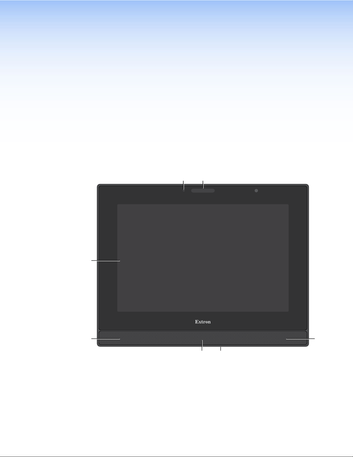
TLP Pro 1225, 1525, and 1725 Series Front Panel Features
Figure 2 shows the TLP Pro 1225MG front panel. The TLP Pro 1525MG and 1725MG are very
similar.
AB
Ambient light sensor (see page 7)
A
Status light
B
Capacitive touch screen
C
Speakers (2)
D
Motion sensor
E
Menu button (MG models only)
F
Figure 2.
TLP Pro 1225MG Front Panel
TLP Pro 1225, 1525, and 1725 Series • Panel Features 6
Page 15

Figure 3 shows the TLP Pro 1225TG front panel. The TLP Pro 1525TG and 1725TG are very
D
E
similar.
AB
C
D
Figure 3. TLP Pro 1225TG Front Panel
The following callouts refer to both figure 2 (see page 6) and figure 3. The links below take
you to figure 2.
Ambient light sensor — Monitors ambient light level and adjusts screen brightness, based
A
on the settings configured using the Setup Menu.
Status light — One LED light bar, above the screen, which can be programmed to provide
B
system feedback. For information about programming this light, see the Global Configurator
Plus and Professional Help File or the Global Scripter Help File.
Capacitive touch screen — With a touch overlay.
C
• The TLP Pro 1225 series models have a 12.1 inch screen with a 1280x800 resolution.
• The TLP Pro 1525 series models have a 15.6 inch screen with 1366x768 resolution.
• The TLP Pro 1725 series models have a 17.3 inch screen with 1920x1080 resolution.
Speakers (2) — Located below the screen, one on each side of the panel, provide stereo
D
audio for video preview and audible feedback from button presses.
Motion sensor — Detects motion between three to five feet from the touchpanel, and at
E
least 15° from the center axis (see Configuring the Motion Sensor on page 17)
Menu Button (MG models only) — Located under the touchpanel. It is used to sctivate the
F
Setup Menu (see page 14).
TLP Pro 1225, 1525, and 1725 Series • Panel Features 7
Page 16

TLP Pro 1225, 1525, and 1725 Series Rear Panel Features
A
B
C
A
D
E
F
G
H
I
Figure 4 shows the TLP Pro 1225MG rear panel. The TLP Pro 1525MG and 1725MG are very
similar.
RESET
MENU
1
2
Figure 4. TLP Pro 1225MG Rear Panel
Mounting plate notches (2) — Fit over the hooks at the top of the mounting plate (see
A
Wall Mounting on page 28).
Reset LED — Provides feedback about the reset status when the user presses the reset
B
button.
Reset button — Pressing the Reset button allows the unit to be reset in any of four
C
different modes (see Reset Modes on page 34).
Menu button — Activates the setup menu (see Setup Menu on page 14).
D
USB connectors (2) — For peripheral controls.
E
Mounting screw slot (2) — Insert the provided screws here. Secure the touchpanel to the
F
mounting plate (see Wall Mounting).
Audio output — For use with headphones or assistive listening devices.
G
HDMI input — For alternative video input.
H
XTP/LAN/PoE input — The TLP Pro 1725MG ships with the Extron PI 140 power injector
I
provided. For the TLP Pro 1225MG or 1525MG, a power injector must be purchased
separately.
• XTP input — Connect the touchpanel to the XTP source using a twisted pair cable,
terminated with an RJ-45 connector. For complete information about which cables to
use, see the user guide for your XTP product.
• LAN input — Connect the touchpanel to the LAN using a twisted pair cable, terminated
with an RJ-45 connector.
• PoE input — the connector can be used with a PoE power injector (see Power over
Ethernet on page 11).
NOTE: Some XTP models are able to remotely power these touchpanels but not
all have that capability. Go to the Extron website and check the product page
for your XTP model to ensure it can power your touchpanel.
An Extron IP Link Pro control processor must also be connected to the same network as the
TouchLink Pro touchpanel.
XTP /
LAN /
PoE
HDMI IN
TLP Pro 1225, 1525, and 1725 Series • Panel Features 8
Page 17

Figure 5 shows the TLP Pro 1225TG rear panel. The TLP Pro 1525TG and 1725TG are very
Marking
B
C
D
E
F
G
H
I
J
A
similar.
12VDC 3A
Rear status light
A
Vesa mounting holes
B
Power supply input
C
USB connectors
D
Figure 5.
HDMI input
E
XTP/LAN/PoE input (see page 10)
F
Audio output (see page 10)
G
TLP Pro 1225TG Rear Panel
1
2
XTP /
PoE /
LANHDMI IN
MENU
RESET
Menu button (see page 10)
H
Reset button (see page 10)
I
Reset LED (see page 10)
J
Rear status light — This LED light bar can be programmed to provide system feedback.
A
VESA mounting holes (4) — For use with D-type VESA mounting kits with the 100 x 100
B
mm mounting pattern.
Power supply input — Connect a 12 VDC, 3.0 A Limited Power Source (LPS) power
C
supply to this DC plug connector.
NOTE: The TLP Pro 1225TG, 1525TG, and 1725TG models have the option to be
powered by a 12 VDC power supply or Power over Ethernet.
ATTENTION:
• Do not power on the touchpanels until you have read the Attention notice on
page 12.
• Ne branchez pas les écrans tactiles avant d’avoir lu la mise en garde page 12.
USB connectors (2) — For peripheral controls.
D
HDMI input — For alternative video input.
E
TLP Pro 1225, 1525, and 1725 Series • Panel Features 9
Page 18

XTP/LAN/PoE input (see figure 5 on page 9)— The TLP Pro 1725TG ships with the
F
Extron PI 140 power injector provided. For the TLP Pro 1225TG or 1525TG, a power injector
must be purchased separately.
• XTP input — Connect the touchpanel to the XTP source using a twisted pair cable,
terminated with an RJ-45 connector. For complete information about which cables to
use, see the user guide for your XTP product.
• LAN input — Connect the touchpanel to the LAN using a twisted pair cable, terminated
with an RJ-45 connector.
• PoE input — The connector can be used with a PoE power injector (see “Power over
Ethernet”, below).
NOTE: Some XTP models are able to remotely power these touchpanels but not
all have that capability. Go to the Extron website and check the product page
for your XTP model to ensure it can power your touchpanel.
An Extron IP Link Pro control processor must also be connected to the same network as the
TouchLink Pro touchpanel.
Audio output — For use with headphones or assistive listening devices.
G
Menu button — Activates the setup menu (see Setup Menu on page 14).
H
Reset button — Pressing the reset button allows the unit to be reset in any of four different
I
modes (see Reset Modes on page 34).
Reset LED — Provides feedback about the reset status when the user presses the Reset
J
button.
TLP Pro 1225, 1525, and 1725 Series • Panel Features 10
Page 19

Connecting Power
XTP Device
touchpanel
1
2
3
12 VDC Power Supply
Power over Ethernet
The TLP Pro 1725MG and 1725TG ship with the Extron PI 140 power injector provided. For
the TLP Pro 1225MG, 1225TG, 1525MG or 1525TG, a power injector must be purchased
separately.
• The TLP Pro 1225MG, 1525MG, and 1725MG must be powered by a PoE power source.
• The TLP Pro 1225TG, 1525TG, and 1725TG can be powered by a PoE power source or by
a 12 VDC power supply.
ATTENTION:
• Do not power on the touchpanels until you have read the Attention notice on page 12.
• Ne branchez pas les écrans tactiles avant d’avoir lu la mise en garde page 12.
Connect a 12 VDC, 3 A power supply to the DC connector on the back of the TLP Pro 1225TG,
1525TG, and 1725TG models.
Figure 6 shows the Extron PI 140. Your power injector may look different.
1. Connect a straight-through Ethernet cable
from the power injector to a switch or router
100-240V~50/60 Hz
1.1A MAX
INPUT OUTPUT
POWERED TLP
LAN
(1). This cable carries network information
from the switch or router to the power supply
input.
2. Connect a second straight-through cable
from the power injector to the XTP/PoE/LAN
connector of the touchpanel (2). This cable
carries the network information and 48VDC
from the power injector to the touchpanel.
Extron PI 140
To Network or
To a TLP Pro
Figure 6. Connecting the Power Injector
3. Connect the IEC power cord to a convenient 100 VAC to 240 VAC, 50-60 Hz power source
(3).
Alternatively, use an Ethernet cable to connect the XTP/LAN/PoE+ port of the interface to a PoE+
switch or connect the touchpanel directly to an XTP model that is capable of remotely powering
a touchpanel (see the note on page 10).
TLP Pro 1225, 1525, and 1725 Series • Panel Features 11
Page 20

ATTENTION:
•
Always use a power supply provided by or specified by Extron. Use of an unauthorized
power supply voids all regulatory compliance certification and may cause damage to
the supply and the end product.
• Utilisez toujours une source d’alimentation fournie ou recommandée par Extron.
L’utilisation d’une source d’alimentation non autorisée annule toute conformité
réglementaire et peut endommager la source d’alimentation ainsi que le produit final.
• The installation must always be in accordance with the applicable provisions of National
Electrical Code ANSI/NFPA 70, article 725 and the Canadian Electrical Code part 1,
section 16.
• Cette installation doit toujours être en accord avec les mesures qui s’applique au
National Electrical Code ANSI/NFPA70, article725, et au Canadian Electrical Code,
partie1, section16.
• These products are intended for use with a UL Listed power source marked “Class 2”
or “LPS” and rated 12VDC, minimum 3.0 A. or 56 VDC (PoE), minimum 0.8 A.
• Ces produits sont destiné à une utilisation avec une source d’alimentation listéeUL
avec l’appellation «Classe2» ou «LPS» et normée 12Vcc, 3,0A minimum ou 56Vcc
(PoE), 0,8A minimum.
• The power supply shall not be permanently fixed to the building structure or similar
structure.
• La source d’alimentation ne devra pas être fixée de façon permanente à une structure
de bâtiment ou à une structure similaire.
• Unless otherwise stated, the AC/DC adapters are not suitable for use in air handling
spaces or in wall cavities. The power supply is to be located within the same vicinity
as the Extron AV processing equipment in an ordinary location, Pollution Degree 2,
secured to the equipment rack within the dedicated closet, podium, or desk.
• Sauf mention contraire, les adaptateurs AC/DC ne sont pas appropriés pour une
utilisation dans les espaces d’aération ou dans les cavités murales. La source
d’alimentation doit être située à proximité de l’équipement de traitement audiovisuel
dans un endroit ordinaire, avec un degré2 de pollution, fixé à un équipement de rack à
l’intérieur d’un placard, d’une estrade, ou d’un bureau.
• Extron power supplies are certified to UL/CSA 60950-1 and are classified as LPS
(Limited Power Source). Use of a non-LPS or unlisted power supply will void all
regulatory compliance certification.
• Les sources d’alimentation Extron sont qualifiées UL/CSA60950-1 et sont
classéesLPS(LimitedPowerSource). L’utilisation d’une source d’alimentation nonlistée ou non-listéeLPS annulera toute certification de conformité réglementaire.
• The length of the exposed wires in the stripping process is critical. The ideal length is
3/16 inches (5 mm). If they are any longer, the exposed wires may touch, causing a
short circuit between them. If they are any shorter, the wires can be easily pulled out
even if tightly fastened by the captive screws.
• La longueur des câbles exposés est primordiale lorsque l’on entreprend de les
dénuder. La longueur idéale est de 5mm (3/16inches). S’ils sont un peu plus longs,
les câbles exposés pourraient se toucher et provoquer un court circuit. S’ils sont un
peu plus courts, ils pourraient sortir, même s’ils sont attachés par les vis captives.
• Do not tin the wire leads before installing into the connector. Tinned wires are not as
secure in the connector and could be pulled out.
• Ne pas étamer les conducteurs avant de les insérer dans le connecteur. Les câbles
étamés ne sont pas aussi bien fixés dans le connecteur et pourraient être retirés.
TLP Pro 1225, 1525, and 1725 Series • Panel Features 12
Page 21

Routing Cables (TG Models)
2
3
4
5
Organize cables behind the rear and base covers for a more aesthetically appealing appearance.
The TLP Pro 1525TG is shown below but the TLP Pro 1225TG and 1725TG are very similar.
111
2
2
3
3
4
4
5
5
Figure 7. TLP Pro 1525TG Cable Organization
1. If necessary, remove the rear and base covers and connect the cables as required (see
Removing the Rear and Base Covers on page 31).
2. Move the clamp at the back (
where the base and back meet (2).
3. If necessary, move the clamp on the base (
4. Run the cables through the raceways on either side of the center hole (
through the slot at the back of the base (5). Multiple cables can be loosely bundled to keep
them organized.
5. Move the rear and base cable clamps back into position and press them down to secure
them in place.
6. Put back the rear and base covers. The base cover must be inserted before the rear cover.
) to one side and run the cables through the restricted gap
1
) to one side.
5
and 4), and
3
TLP Pro 1225, 1525, and 1725 Series • Panel Features 13
Page 22

Setup Menu
The TLP Pro 1225, 1525, and 1725 series touchpanels can be set up by using the on-screen
setup menu. This section provides information about accessing the Setup Menu and the six
sub-menus:
Setup Menu
To open the setup menu, press the recessed Menu button, using a small screwdriver. The button
can be found on the rear panel:
• MG models — see figure 4,
• TG models — see figure 5,
• The MG models also have a Menu button on the front panel as the rear panel is inaccessible
when the touchpanel is mounted in a wall (see figure 2, F, on page 6).
The menus open at the
the top of the screen. These open the following screens:
• Status Screen (see page 15)
• Network Screen (see page 15)
• Display Screen (see page 17)
• Audio Screen (see page 18)
• Input Screen (see page 18)
• Advanced Screen (see page 20)
The button for the selected screen is yellow; the buttons for the remaining screens are black.
There is also a red
the menu screens.
In this section, the figures show the screens for the TLP Pro 1225MG. The screens for the other
touchpanels are very similar.
, on page 8.
D
, on page 9.
H
Status screen. There are six different buttons in the navigation panel at
Exit button in the top right corner of the screen. Pressing this button closes
TLP Pro 1225, 1525, and 1725 Series • Setup Menu 14
Page 23

Status Screen
Status
Model: TLP Pro 1225MG
Part Number: 60-1787-02
Firmware
Version:
Bootloader
Version:
PoE Status: Active
Figure 8. Status Screen
The Status screen is read-only. The Info panel provides basic information about the
touchpanel. Each of the other five panels shows a summary of the information on the other
screens. No values can be changed from this screen.
Pressing any of those five panels opens the corresponding screen in exactly the same way as
pressing the buttons in the top navigation bar.
The green bubble shown in the
red square shown in the Advanced panel indicates that no control processor is connected.
Network Screen
The Network screen allows you to set the DHCP status and, if DHCP is set to Off, the network
addresses for the touchpanel. Verify with your network administrator whether the IP address for
the touchpanel is assigned by DHCP or set manually. If it is set manually, you need to obtain an
IP address, a subnet mask, a gateway address, and a Domain Name Server (DNS) IP address
from the network administrator.
Network
Info
1.02.0001-b001
1.03.0000
Display
IP Address:
DHCP:
Host Name:
Master Volume:
Master Mute: Off
Controller IP: 192.168.254.250
Project Size: 1/196 MB
Audio
Network
192.168.254.251
Off
TLP-AB-CD-EF
Audio
100
Advanced
Network panel indicates that there is a network connection. The
Input
Advanced
Resolution:
GUI Project:
Sleep Timer:
Input
HDMI Port: No Signal
XTP: 1280x720
Display
1280x800
1280x800
5 Minutes
Exit
HDCP
Status Display AudioInput Advanced Exit
IP Address:
Subnet Mask:
Gateway:
Network
TLP-AB-CD-EFHost Name:
192.168.254.251
255.255.255.0
0.0.0.0
On
DHCP
Off
DNS Primary:
Domain Name:
Mac Address:
127.0.0.1
00-05-A6-AB-CD-EF
ApplyRevert
Figure 9. Network Screen
1. If IP addresses are assigned by DHCP, press On. If the IP address is to be assigned
manually, press
• When DHCP is off, the Host Name is grayed out and cannot be edited. All
O.
addresses can be edited (as shown in figure 9).
• When DHCP is on, the Host Name can be edited. The addresses are grayed out
and cannot be edited because they are set by the DHCP server.
TLP Pro 1225, 1525, and 1725 Series • Setup Menu 15
Page 24

2. If DHCP is on, press the Host Name button to edit the host name. The Host Name dialog
Saved
box opens:
Figure 10. Alphanumeric Keypad
Use the keypad to enter a new name, which appears in the Host Name text box.
3. If DHCP is disabled, set the unit IP address, subnet mask, gateway address, and DNS
server address.
a. Press the button for the address to be edited. A screen opens, showing the address
and a numerical keypad.
IP Address
192 168 254 251
Clear
1
4
7
Back
3
2
6
5
98
0
OK
Cancel
Figure 11. Numeric Pad for Setting IP Addresses
b. Select an octet and enter the 3-digit value (leading zeroes in the octet are ignored).
NOTES:
• Octets can have any value between 0 and 255.
• If you attempt to enter an invalid number, for example 892, you are able to
enter the 89 but the 2 cannot be entered.
• When a valid 3-digit value is entered, the next octet is automatically selected.
c. Press OK to save the changes and return to the Network screen or press Cancel to
return to the Network screen without saving the changes.
4. If you have changed any of the values in the Network screen,
the background color of the button changes to blue. Press
Apply to apply the new values or press Revert to return to
0.0.0.10
Unsaved
the previous values without saving the changes. The button
returns to gray.
If you have not made any changes, the
buttons are grayed out.
Apply and Revert
0.0.0.10
Figure 12. IP Address,
unsaved (top) and
saved (bottom).
TLP Pro 1225, 1525, and 1725 Series • Setup Menu 16
Page 25

Display Screen
Status Display AudioInput Advanced Exit
Network
Sleep Timer
Auto Brightness
On Off
2
3
4
Minutes
On Off
Figure 13. Display Screen
The Display screen allows you to set the Sleep Timer, Auto Brightness,
LCDBrightness, and Wake on Motion.
• Sleep Timer — Toggle between On and O.
• If the sleep timer is on, after a period of inactivity, the screen goes dark to save power
(Sleep mode). Use the up and down arrows to set how long the period of inactivity
should be. The value can be between 1 and 120 minutes.
• If the sleep timer is Off, the panel does not enter sleep mode.
• Auto Brightness — Toggle between On and O.
• If Auto Brightness is on, the light sensor (MG models: see figure 2,
page 6; TG models see figure 3,
ambient light detected and automatically provides a suitable amount of screen
backlighting for the situation.
• If Auto Brightness is off, the screen brightness is not affected by changes in the
• LCD Brightness — Use the slider control to adjust the screen brightness between 0 and
• Wake on Motion — Toggle between On and O. For this to work, the touchpanel must be
ambient light.
100.
in sleep mode.
• If Wake on Motion is on, and the touchpanel is in sleep mode, any motion detected
by the motion sensor (MG models: see figure 2,
figure 3,
on page 7) wakes the panel from sleep mode. The screen lights and all
E
buttons become functional.
• If Wake on Motion is off, the panel does not wake in response to nearby motion, and
the touchpanel can be activated by pressing anywhere on the screen.
LCD Brightness
050100
Wake on Motion
On Off
on page 7) monitors the amount of
A
E
, on
A
, on page 6; TG models see
Configuring the Motion Sensor
The Motion Sensor (see figure 2, E) detects motion between three to five feet from the
touchpanel, and at least 15° from the center axis.
• If the Sleep Timer has been set and no motion has been detected for a user-defined
period of time, the touchpanel enters sleep mode.
• If the Sleep Timer has not been set, the touchpanel does not enter sleep mode.
• If Wake on Motion has been set and motion is detected by the sensor while the screen is in
sleep mode, the screen display is restored and active.
• If Wake on Motion has not been set and the screen is in sleep mode, touch the screen to
restore it to an active state.
TLP Pro 1225, 1525, and 1725 Series • Setup Menu 17
Page 26

Audio Screen
Status Display Audio InputAdvanced Exit
100
Master
50
0
Network
100
50
Click
0
100
Sound
50
0
100
50
HDMI
0
XTP
100
50
0
Figure 14. Audio Screen
On the Audio screen, use the slider controls to adjust the Master, Click, Sound, HDMI, and
XTP volume settings.
• The Master panel allows you to click on the appropriate icon to set whether the audio is
heard through the speakers, headphones, or both.
It also sets the maximum volume threshold for all the other sound volume settings. For
example, if the master volume is set to
80 (80 percent of maximum), when the HDMI volume
is set to 50, it is equivalent to only 40 percent of maximum (50 percent of 80 percent).
• Click sets the volume for audible feedback that accompanies events such as a screen
button being pressed.
• Sound sets the volume of audio from any audio file playback.
• HDMI sets the volume of the HDMI input.
• XTP sets the volume of the XTP input.
Click on the speaker and headphones icon at the bottom of each panel to toggle between audio
on (black button) and audio mute (yellow button). The
Input Screen
Sound audio is muted in figure 14.
Status Display Audio Input Advanced Exit
Native Display: 1280x800 @ 50 Hz, HDMI, LPCM-2Ch, Extron
HDMI
XTP
HDMI
XTP
Network
Signal: 1920x1080 @ 59.94
EDID: 1280x800 @ 50 Hz
Signal: 1280x720 @ 60
EDID: 1280x800 @ 50 Hz
Aspect
Ratio
Fill
Fill
Input Configuration
Input Status
HDCP
Authorize
On
On
HDMI
HDMI
HDMI
HDMI
EDID
Minder
Edid
Edid
LPCM-2-Ch
HDMI, LPCM-2Ch
LPCM-2-Ch
HDMI, LPCM-2Ch
Settings
HDCP
HDCP
Image
Adjust
Adjust
Figure 15. Input Screen
The Input screen provides information about the video input signal status and allows
configuration of the input signal.
At the top of the screen the native display EDID information is shown. Figure 15 shows this is
1280x800 @ 50 Hz, HDMI, LPCM-2Ch. for the TLP Pro 1225MG.
TLP Pro 1225, 1525, and 1725 Series • Setup Menu 18
Page 27

The upper panel shows read-only information about the input signal status. The green bar
indicates whether the current input is HDMI or XTP. In figure 15 on page 18, the input is
HDMI. The XTP input status information is obtained from the last XTP input signal.
The lower panel allows adjustments to the input configuration.
• Aspect Ratio: Press this button to toggle between Fill, which stretches the image so that
it fills the entire screen, and Follow, which maintains the aspect ratio of the input signal.
• HDCP Authorization: Press the button to toggle between On (default) and O. When HDCP
Authorize is On, HDCP-encrypted input signals pass to the screen.
• EDID Minder: Press the EDID button to toggle between using the EDID of the touchpanel
(1280x800 @ 50Hz for the TLP Pro 1225MG) or setting a resolution and refresh rate. The
button is black if the native display is used and turns yellow if you are setting the EDID
manually.
Pressing the button opens the
EDID Minder window. When setting the EDID manually, only
the Resolution panel is initially populated. Once the resolution is selected, the available
refresh rates for that resolution are displayed. When both the resolution and refresh rate are
selected, press Apply.
EDID Minder — HDMI
Match EDID to
852x480
800x600
1024x768
1024x852
1280x768
1280x800
1360x765
1360x768
1365x768
1024x1024
1366x768
Figure 16. EDID Minder
Display Native: 1280x800 @ 50 Hz, HDMI, LPCM-2Ch, Extron
Resolution
75
60
50
Refresh Rate (Hz)
CancelApply
• Image Settings: Press the Adjust button to open the Image Settings window. Select
the input (HDMI or XTP), or adjust Brightness, Contrast, Detail, and Overscan.
HDMI
XTP
1920x1080 @ 59.94
LPCM-2-Ch
HDCP
Brightness 64
Contrast
Detail
Overscan
64
64
5%
Exit
Figure 17. Image Settings
64
Default
TLP Pro 1225, 1525, and 1725 Series • Setup Menu 19
Page 28

1. Select the video input by pressing the appropriate button (HDMI or XTP).
The EDID information is shown in a read-only panel.
2. To adjust Brightness, Contrast, Detail, or Overscan, press the appropriate button. A
small window opens to the right of the screen. For Brightness, Contrast, and Detail,
the window shows the current value with right and left arrows to increment or decrement the
value. To change the value more quickly, use the slider underneath.
To reset the value to default, press the
Contrast, and Detail is 64. All three parameters can be adjusted to any value between 1
and 127.
3. Press Overscan. A small window opens offering the options 0%, 2.5%, and 5%. The default
setting is
4. Press Exit to save the changes and return to the Input screen.
Advanced Screen
Default button. The default value for Brightness,
5%.
Status Display AudioInput Advanced Exit
Touchpanel Name:
Controller Name:
Controller IP: 192.168.254.250
-----------------------------Global Configurator Project
Name:
Version:
Creation Date:
Revision Date:
On
Network
System GUI Project
TLPPro1225_ABCDEF
IPCPPro350_FEDCBA
N_Campus.gcpro
0.0.22.0
6/22/2020 2:15:26 PM
6/25/2020 1:47:18 PM
Menu Pin
Off
Change
Name:
Resolution:
Creation Date:
Revision Date:
Version: 0.0.9
Project Size:
Storage Size:
Project Usage:
N_Campus.gdl
1280x800
6/26/2020 11:31:55 AM
6/27/2020 12:06:31 PM
3 MB
196 MB
2%
Figure 18. Advanced Screen
The System and GUI Project panels are read only, providing information about the system.
Menu PIN
Press Change to open the PIN Setup window. The PIN setup options allow you to enable,
disable, or change the setup menu PIN. The PIN is a 4-digit number. Each digit can have any
value from
0 through 9.
1. Press a number on the keypad. A blue circle appears in the first box.
Enter New Menu PIN
Back
213
456
8
7
9
0
Cancel
Figure 19. Numeric Keypad for Setting PIN
2. Select the other three digits for the PINs. The fourth circle appears momentarily and then the
screen changes to Confirm New Menu Pin.
3. Enter the PIN a second time. When the PIN entered on the second occasion matches the
PIN entered on the first occasion, the PIN is set and the dialog closes.
TLP Pro 1225, 1525, and 1725 Series • Setup Menu 20
Page 29

Configuration Software
This section of the user guide provides information about:
• Configuration Software
• Install Software
• Using the Software
• TLP Pro 1225, 1525, and 1725 Series Web Page
• Updating the Firmware
Configuration Software
Use Toolbelt to provide device information, firmware updates, and configuration of network
settings, system utilities (reset, reboot), and user management (username and password) for
TouchLink Pro devices.
GUI Designer, Global Configurator Plus and Professional, and Global Scripter are used to design
the touchpanel screen and assign functions to the screen elements.
Install Software
The TLP Pro 1225, 1525, and 1725 series touchpanels are compatible with GUI Designer, Global
Configurator Plus and Professional, Global Scripter, and Toolbelt.
All four software products can be downloaded from www.extron.com
NOTE: Ensure you are downloading the correct software. These touchpanels are not
compatible with Global Configurator 3 or GUI Configurator.
1. Select the Download tab (
2. Click the Software (
2
).
1
) option at the bottom of the page.
Figure 20. Software Downloads from the Extron Website
TLP Pro 1225, 1525, and 1725 Series • Configuration Software 21
Page 30

3. You may see the product immediately, for example Global Configurator Plus and Professional
2
2
3
(see figure 21, 1). Use the left and right arrows (2) to scroll through all the highlighted
products. If the software is not shown, click the initial letter of the product in the alphabet
menu (3).
111
2
2
3
3
Figure 21. Software Download Center
4. Clicking directly on the product name takes you to the product page, which provides
more information about the software. Click Download and, on the new page, provide the
information requested. An executable file (.exe) is placed in your default Downloads folder.
Clicking on a letter from the alphabet menu generates a list of software products with
that initial letter. Scroll through the search results until you find the desired product. Click
Download and, on the new page, provide the information requested. An executable file
(.exe) is placed in your default Downloads folder.
2
2
NOTES:
• If you select Global Configurator Plus and Professional, there is a check box that
allows you to download Toolbelt at the same time.
5. Run the executable file to install the software. By default, your computer creates a new folder
• You need an Extron Insider account to run Global Configurator Plus and
Professional. To obtain one, contact the Extron Sales Department.
• Ensure you are downloading Global Configurator Plus and Professional.
at C:\Program Files\Extron or C:\Program Files (x86)\Extron.
TLP Pro 1225, 1525, and 1725 Series • Configuration Software 22
Page 31

Using the Software
Use GUI Designer and Global Configurator Plus and Professional to design and configure a
graphical user interface (GUI) for the TouchLink Pro touchpanel.
1. Design the layout of the screen text and graphics using GUI Designer, which is a
2. After the user interface has been designed, the project is saved, built, and imported into
3. Use Global Configurator Plus and Professional to assign functions to the text and graphics of
4. After assigning the control functions, the project is rebuilt and uploaded to the control
The GUI Designer, Global Configurator Plus and Professional, and Global Scripter software
provide versatility and adaptability for control of an AV system as it grows and evolves.
GUI Designer — Use the GUI Designer software to design the screen layout for the touchpanel
(see the GUIDesigner Help File for step-by-step instructions and more detailed information).
Global Configurator Plus and Professional — Use the Global Configurator Plus and
Professional software to assign functions to the text and graphics of the interface (see the
Global Configurator Plus and Professional Help File for step-by-step instructions and more
detailed information). The Global Configurator Plus and Professional Help File also includes an
introduction to the software and sections on how to start and configure a project.
Global Scripter — As an alternative to Global Configurator Plus and Professional, use the
Global Scripter software to program the touchpanel, using Python
Python library (ControlScript) and Global Scripter modules (see the Global Scripter Help File for
more detailed information).
Toolbelt — The touchpanel can use the Toolbelt software for device discovery, device
information, firmware updates, and configuration of network settings (see the Toolbelt Help File
for more detailed information).
Windows-based application. You can either customize an existing template or create an
entirely new interface. GUIDesigner offers several templates.
Global Configurator Plus and Professional.
the interface.
processor and touchpanel.
Alternatively, instead of using Global Configurator Plus and Professional, use Global Scripter
to program control functions for the text and graphic items of the interface.
™
3.5 with an Extron-exclusive
TLP Pro 1225, 1525, and 1725 Series • Configuration Software 23
Page 32

TLP Pro 1225, 1525, and 1725 Series Web Page
To access the touchpanel default web page, enter the IP address of the unit into the web
browser of a PC connected to the same subnet. A log-in page opens.
Figure 22. TLP Pro 1525MG Login Page
Figure 22 shows the login page for the TLP Pro 1525MG. The login pages for the other
touchpanels are very similar.
1. Enter the Username and Password. The factory configured passwords for all accounts on
this device have been set to the device serial number. Passwords can be changed during
configuration. Passwords are case sensitive.
NOTE: If the device is reset to default settings, the passwords are reset to the default
password, which is extron (for either admin or user).
2. The touchpanel web page opens:
Figure 23. TLP Pro 1525MG Web Page
Figure 23 shows the web page for the TLP Pro 1525MG. The web pages for the other
touchpanels are very similar.
TLP Pro 1225, 1525, and 1725 Series • Configuration Software 24
Page 33

• There is a single page, most of which is read-only, providing general and network information
about the unit. Use the Setup Menu (see page 14) or Toolbelt to configure the
touchpanel network settings.
• Click Licence Information to see information about Network Port Requirements and
Licensed Third-Party Software Used by the Touchpanels for the TLP Pro 1225, 1525, and
1725 series touchpanels.
• Use the Firmware Uploader panel to upgrade the unit firmware (see “Updating the
Firmware” in the following section).
Updating the Firmware
Firmware for all the touchpanels can be upgraded using Toolbelt or the touchpanel web page.
Before starting, consult your IT team and ensure that the touchpanel has a unique IP address.
Downloading Firmware
1. Open the Extron website and select the Download tab (
2. Click the Firmware (
) option at the bottom of the page.
2
1
).
Figure 24. Firmware Download
TLP Pro 1225, 1525, and 1725 Series • Configuration Software 25
Page 34

The Firmware Download Center page opens:
Figure 25. Selecting Firmware to Download
3. Click the letter T from the list of letters (
4. Scroll down the page until you find the firmware for your touchpanel model.
NOTE: Your product will appear in this list only if a new version of the firmware has
been released since the product was first introduced.
1
).
5. (Optional) Click Release Notes (
6. Click Download (
7. Follow the on-screen instructions to download the program. An executable file is
downloaded to the PC.
8. Go to the Downloads folder and click on the file to install the firmware on the PC. By
default, it is stored at
name>\<rmware version>.
9. Upload this file to the touchpanel using the touchpanel web page (see “Updating Firmware
Using the Touchpanel Web Page”) or Toolbelt (see “Updating Firmware Using Toolbelt”).
).
3
C:\\Program Files (x86)\Extron\Firmware\<product
) for more information about the firmware.
2
Updating Firmware Using the Touchpanel Web Page
1. If you have not already done so, download the firmware file to a computer on the same
network as the touchpanel (see the previous section).
2. Open the TLP Pro 1225, 1525, and 1725 Series Web Page (see page 24).
Figure 26. Touchpanel Web Page: Firmware Uploader
3. Click Browse and navigate to the firmware location. Select the firmware file and click Open.
4. Click Upload. The firmware file is uploaded to the touchpanel. Follow the on-screen
instructions.
Updating Firmware Using Toolbelt
For complete information about using Toolbelt to update the touchpanel firmware, see the
Toolbelt Help File.
TLP Pro 1225, 1525, and 1725 Series • Configuration Software 26
Page 35

Mounting
This section outlines the various options for:
• Mounting the TLP Pro 1225MG, 1525MG, and 1725MG
• Rack Mounting
• Wall Mounting
• Mounting the TLP Pro 1225TG, 1525TG, and 1725TG
• Desktop Mounting
• VESA Mounting
Mounting the TLP Pro 1225MG, 1525MG, and 1725MG
Rack Mounting
These touchpanels can be mounted in any standard 19-inch equipment rack, using the optional
rack mounting kit.
• TLP Pro 1225MG: RM 2 kit
• TLP Pro 1525MG: RM 3 kit
• TLP Pro 1725MG: RM 3 kit
Read the Underwriters Laboratories Guidelines for Rack Mounting below and follow the
instructions provided with the appropriate kit.
Underwriters Laboratories Guidelines for Rack Mounting
The following Underwriters Laboratories (UL) guidelines are relevant to the safe installation of
these products in a rack:
• Elevated operating ambient temperature — If the unit is installed in a closed or multi-
unit rack assembly, the operating ambient temperature of the rack environment may be
greater than room ambient temperature. Therefore, install the equipment in an environment
compatible with the maximum ambient temperature (Tma: +104 °F, +40 °C) specified by
Extron.
• Reduced air flow — Install the equipment in the rack so that the equipment gets adequate
air flow for safe operation.
• Mechanical loading — Mount the equipment in the rack so that uneven mechanical
loading does not create a hazardous condition.
• Circuit overloading — Connect the equipment to the supply circuit and consider the
effect that circuit overloading might have on overcurrent protection and supply wiring.
Give appropriate consideration to the equipment nameplate ratings when addressing this
concern.
• Reliable earthing (grounding) — Maintain reliable grounding of rack-mounted equipment.
Pay particular attention to supply connections other than direct connections to the branch
circuit (such as the use of power strips).
TLP Pro 1225, 1525, and 1725 Series • Mounting 27
Page 36

Wall Mounting
The touchpanels can be mounted into drywall. The diagram in this section shows the
TLP Pro 1525MG. Mount the TLP Pro 1225MG or 1725MG in the same way.
ATTENTION:
Some local building codes require the touchpanel to be mounted in a wall box such as the
Extron BB 700M (see Mounting with a wall box on page 29).
If local codes permit, you may mount the touchpanel without the wall box (see Mounting
without a wall box on page 30).
•
Do not install the TLP Pro 1225MG, 1525MG, or 1725MG in a fire resistant rated wall
or partition assembly.
• Ne pas installer le TLP Pro 1225MG, le 1525MG, ou le 1725MG dans un mur résistant
au feu ou une cloison.
• All structural steps and electrical installation must be performed by qualified personnel
in accordance with local and national building codes and electrical codes.
• Toute étape structurelle et installation électrique, doit être effectuée par un personnel
qualifié, conformément aux codes du bâtiment, aux codes incendie et sécurité, et aux
codes électriques, locaux et nationaux.
TLP Pro 1225, 1525, and 1725 Series • Mounting 28
Page 37

Mounting with a wall box
Hold the touchpanel at a slight angle.
1
Install BB 700M (optional).
2
6
4
Mount the touchpanel over the two
hooks on the mounting plate.
Add the mounting plate. Align with
the wall box and mark holes for screws.
Secure the mounting plate
to the wall with screws (4).
TLP Pro 1525MG
5
3
Place the provided mounting screws (2)
with washers in the mounting screw slot
in the touchpanel.
8
Secure the touchpanel by tightening the
mounting screws against the base of the
Back View
mounting plate.
Figure 27. Wall Mounting the TLP Pro 1525MG with the BB 700M
The TLP Pro 1225MG, 1525MG, or 1725MG can be mounted using the BB 700M wall box.
1. Cut a hole in the drywall, 9.55 inches (24.26 cm) wide x 6.55 inches (16.64 cm) high, and
install the BB 700M back box (must be purchased separately), as described in the BB 700M
Installation Guide (see www.extron.com).
2. Place the metal mounting plate against the wall, mark the four mounting holes, and drill four
pilot holes.
3. Secure the mounting plate with four #10 screws.
4. Run and connect cables to the rear of the touchpanel (see TLP Pro 1225, 1525, and 1725
Series Rear Panel Features on page 8).
5. Insert the two provided Phillips pan head #6-32 x ¾ inch length screws with washers in the
mounting screw slot (see figure 4 on page 8).
6. Hold the touchpanel at a slight angle and lower the notches at the top of the rear panel (see
figure 4) over the hooks of the mounting plate.
7. Swing the bottom of the touchpanel inwards so that it lies flat against the mounting plate
with the tongue at the bottom of the mounting plate sitting in a groove in the bottom of the
touchpanel.
8. Secure the touchpanel to the mounting plate with the mounting screws.
TLP Pro 1225, 1525, and 1725 Series • Mounting 29
Page 38

Mounting without a wall box
e mounting plate
This procedure can be adapted to mount the touchpanel in furniture, such as a lectern.
1. Download the cut-out template for your touchpanel from www.extron.com. Print it at 100%
(no scaling).
2. Use the template to mark the wall, cut the hole, and drill the four pilot holes.
The size of the cut-out hole is 9.25 inches (23.50 cm) wide x 6.25 inches (15.88 cm) high for
the TLP Pro 1225MG, 1525MG, or 1725MG.
3. Secure the mounting plate and complete the installation, as described in steps 3-8 on
page 29.
Secur
333
to the wall.
Use cut-out template
111
to cut hole in the wall.
Figure 28. Mounting Without a Wall Box
TLP Pro 1225, 1525, and 1725 Series • Mounting 30
Page 39

Mounting the TLP Pro 1225TG, 1525TG, and 1725TG
2
Removing the Rear and Base Covers
Some of these procedures require the rear and base covers to be removed. You must remove
the rear cover before you can remove the base cover.
111
222
Figure 29. Remove the Rear and Base Covers
1. Use the provided Extron removal tool. There is one notch on each side of the rear cover
(figure 29, 1). Insert the tool into the notch to release the catch.
2. Use the removal tool to remove the base cover. There are two notches at the back of the
base (2).
Desktop Mounting
The TLP Pro 1225TG, 1525TG and 1725TG come assembled with stands that allow the units to
be placed on any suitable flat surface (for example a desk, table, or lectern).
Placement without a Mounting Kit
Figure 30 shows the base of the TLPPro1225TG, with the cover removed to indicate the
position of the mounting holes. The base of the TLP Pro 1525TG and 1725TG are similar and the
spacing of the mounting holes (figure 30, 1) is identical.
2
2
111
Figure 30. TLP Pro 1225TG Base, Showing Mounting Holes
TLP Pro 1225, 1525, and 1725 Series • Mounting 31
111
Page 40

1. Mark the location of two mounting holes, 4.96 inches (126.0 mm) apart. This measurement
is the same for the TLP Pro 1225TG, 1525TG, and 1725TG.
2. Drill two pilot holes into the desktop.
3. Remove the cover of the touchpanel base.
4. Insert two #10 flat-head wood screws (not provided) through the touchpanel and align them
with the two pilot holes.
5. Secure the touchpanel to the tabletop.
6. Replace the cover to the base.
Placement with a Kensington Security Lock
111
Figure 31. TLP Pro 1225TG Base, Showing Kensington Security Slot
For added security, attach a Kensington Security Lock (not provided) to the metal-reinforced slot
on the rear edge of the base. Figure 31 shows the rear edge of the TLP Pro 1225TG base. The
bases of the TLP Pro 1525TG and 1725TG are very similar.
Follow the instructions that are provided by the manufacturer to install the lock.
Placement with a SMA-1 swivel mount adapter
All three touchpanels can also be mounted with the optional Extron SMA-1 swivel mount adapter,
which allows them to be mounted permanently and swivel up to 180° in either direction.
1. Remove the rear cover and base cover (see Removing the Rear and Base Covers on
page 31).
2. Attach the conduit, insulation disk, and swivel disk and configure the set screws to allow for
the degree of swivel that is required (see the SMA-1 Swivel Mount Adapter Kit User Guide,
at www.extron.com).
3. Place the mounting hole in the base over the conduit of the SMA-1.
4. Secure the unit with the backing plate and locking nut as described in the SMA-1 Swivel
Mount Adapter Kit User Guide.
VESA Mounting
The TLP Pro 1225TG, 1525TG, and 1725TG touchpanels have VESA FDMI Type D 100 mm
mounting patterns that can be used for VESA mounting with an appropriate third-party mounting
kit.
Before VESA mounting, the base of the touchpanel must be removed.
1. Remove the rear cover and base cover (see Removing the Rear and Base Covers).
2. If necessary, remove cables from the raceway in the base by reversing the procedure
described in Routing Cables (TG Models) on page 13. If necessary, cut the plastic ties
that bundle the cables together.
3. Remove the screws holding the hinges to the touchpanel.
NOTE: The spanner drive screws holding the hinges require a #6 spanner bit or
#6 spanner head screwdriver (not provided).
4. Lift the TLP away from the base.
5. Follow the instructions provided with the VESA mounting kit.
TLP Pro 1225, 1525, and 1725 Series • Mounting 32
Page 41

Reference Material
This section describes:
• Best Practices for Cleaning Your Extron Products
• Network Port Requirements and Licensed Third-Party Software Used by the
Touchpanels
• Reset Modes
• Secure Sockets Layer (SSL) Certificates
• IEEE 802.1X Certificates
Best Practices for Cleaning Your Extron Products
Depending on the device, application, and location,
there may be times when it becomes necessary
to clean your Extron product. Frequently touched
devices, such as touchscreens and button panels,
require regular cleaning to ensure their surfaces
remain sanitary. Plastic surfaces and cosmetic
finishes can be damaged by long term exposure
to chemicals. Therefore, Extron recommends the
following guidelines when cleaning our products.
All Extron products can be safely cleaned with:
1. 70% concentration or higher Isopropyl Alcohol
2. Disinfectant cleaners that:
• Are non-ammonium based (for example,
contains no ammonium chloride)
• Contain 2% or less sodium hypochlorite (for example, 2% bleach, 98% water)
Regardless of the device, it is important to follow these general guidelines when cleaning:
1. If possible, unplug the device.
2. Spray the cleaner on a lint-free cloth until the cloth is damp.
3. Do not spray the cleaner directly onto the product.
4. Gently clean the product surface using the cloth.
Your health and safety are our top priority. Keeping devices clean, especially those in high-traffic
environments and high-use applications, is a crucial step in minimizing the spread of infections.
Please contact us if you have any questions about the guidelines outlined in this section or if you
have a question about cleaning a specific Extron product.
Network Port Requirements and Licensed Third-Party Software Used by the Touchpanels
For information about network port requirements and licensed third-party software for the
TLP Pro 1225, 1525, and 1725 series touchpanels, see the Pro Series Control Product Network
Ports and Licenses Guide, which is available at www.extron.com.
TLP Pro 1225, 1525, and 1725 Series • Reference Material 33
Page 42

Reset Modes
Use Factory Firmware
These touchpanels have four reset modes that are initiated by pressing the Reset button:
• Use Factory Firmware
• Reset All IP Settings
• Reset to Factory Defaults
• Enable or Disable the DHCP Client
The
Reset button is found on the rear panel (see figure 4,
or figure 5,
This mode is used to boot up the unit with factory-installed firmware for a single power cycle
in the event of a firmware update that failed or incompatibility issues arising with user-loaded
firmware.
, on page 9, for TG models).
I
, on page 8, for MG models;
C
Activation
1. On the touchpanel, hold down the recessed Reset button while applying power to the
unit. When power is restored, the Reset LED lights. Hold the
seconds before releasing it. The touchpanel enters factory firmware mode.
2. Upload new firmware to the unit as desired (see Updating the Firmware on page 25).
NOTE: Do not continue to operate the touchpanel using the factory firmware version. If
you want to use the factory default firmware, you must upload that version again (see
Updating the Firmware).
Reset button for a further two
Result
The unit reverts to factory-installed firmware. Event scripting does not start if the unit is powered
on in this mode. All user files and settings such as drivers, adjustments, and IP settings are
maintained.
NOTE: To return the unit to the firmware version that was running prior to the reset, cycle
power to the unit.
Reset All IP Settings
This mode resets all IP settings to factory defaults.
Activation
To reset all IP settings:
1. Hold down the Reset button until the Reset LED blinks twice (once at 3 seconds and again
at 6 seconds).
2. Release and press Reset momentarily (for <1 second) within 1 second. Nothing happens if
the momentary press does not occur within 1 second.
Result
Reset All IP Settings mode:
• Sets the IP address back to factory default (192.168.254.251).
• Sets the subnet back to factory default (255.255.255.0).
• Sets the default gateway address to the factory default (0.0.0.0).
• DNS Primary address back to the factory default (127.0.0.1).
• Sets the DHCP back to factory default (Off).
• Sets the Hostname back to factory default (TLP-Pro-1225MG-AB-CD-EF).
• Sets the Domain name back to factory default (Blank).
TLP Pro 1225, 1525, and 1725 Series • Reference Material 34
Page 43

Reset to Factory Defaults
This mode resets all IP settings and touchpanel settings, including passwords, to factory defaults
and removes all configurations. It allows you to start over with configuration and uploading.
NOTES:
• The factory configured passwords for all accounts on this device have been set to the
device serial number. Passwords can be changed during configuration. Passwords are
case sensitive.
• If the device is reset to default settings, the password changes to the default password.
The default password is extron (for either admin or user accounts).
Activation
To reset the unit to all factory default settings:
1. Hold down the Reset button until the Reset LED blinks three times (once at 3 seconds,
again at 6 seconds, and again at 9 seconds).
2. Release and press Reset momentarily (for <1 second) within 1 second. Nothing happens if
the momentary press does not occur within 1 second.
Result
This mode performs a complete reset to factory defaults (except the firmware).
• Does everything Reset All IP Settings mode does.
• Removes touchpanel user interface layout and configurations.
• Resets all touchpanel settings, including passwords, to factory default.
Enable or Disable the DHCP Client
This mode toggles between DHCP enabled and DHCP disabled. This can also be carried out
from the Network Screen of the Setup Menu (see page 15).
Activation
To enable or disable the DHCP client for the LAN port:
1. Press the Reset button five times (consecutively).
2. Release the button. Do not press the button within 3 seconds, following the fifth press.
Result
If DHCP was enabled, it is now disabled. The Reset LED blinks three times.
If DHCP was disabled, it is now enabled. The Reset LED blinks six times.
NOTES:
• By default DHCP is off and the unit uses a static IP address.
• When you disable DHCP, the unit reverts to using the previously-set static IP address.
TLP Pro 1225, 1525, and 1725 Series • Reference Material 35
Page 44

Secure Sockets Layer (SSL) Certificates
Extron TouchLink Pro products ship with factory-installed SSL certificates created by Extron. If
you want or are required to use a different SSL certificate at your installation site, then you can
use system utilities in the Toolbelt software to change the SSL certificate at any time. The Toolbelt
Help File provides instructions on how to apply an SSL certificate.
NOTES:
•
You must run Toolbelt as an administrator.
• Some certificates require a passphrase that is created when the certificate is created.
If a passphrase is required, you must enter that passphrase before uploading and
applying the certificate.
These devices support standard OpenSSL certificate encodings such as .pem (Privacyenhanced Electronic Mail) and .der (Distinguished Encoding Rules) file types. PEM file types are
ASCII encoded and are the required format for uploading to the Extron control product. DER file
types are binary encoded and can typically have several file extension variations, such as .crt and
.cer. There are many standard tools that can convert from DER to PEM file encodings if needed.
NOTE: A DER format file must be converted to PEM encoding before uploading it to the
button panel, control processor, touchpanel, or collaboration receiver.
To properly create the certificate for uploading to Extron control devices, ensure that the
certificate file meets the following requirements:
• contains X.509 certificate information
• contains public and private keys
• uses PEM encoding
NOTE: ITU-T standard X.509 covers aspects of public key encryption, digital cryptography,
Contact your IT administrator for more information on what tools and policies are required to
obtain or create the SSL certificate and, if necessary, the corresponding passphrase.
IEEE 802.1X Certificates
IEEE 802.1X is a standard that enables port-based network access control via an authentication
server. The protocol requires that all devices must be authenticated before gaining privileges to
access the secure part of the network.
The Extron implementation of 802.1X supports PEAP - MSCHAPV2 and EAP - TLS methods of
authentication. This section of the guide details the Certificate File Requirements and the Private
Key File Requirements to be used in the system.
Extron provides resources for learning about 802.1X implementation:
• The Extron 802.1X Technology Reference Guide, available from www.extron.com, is the
• The Toolbelt Help File provides detailed step-by-step information on using the software to
• The 802.1X Primer white paper, also available from www.extron.com, provides a general
NOTES:
certificates, and validation.
primary resource for background information, system planning, topology, and how to set up
these systems.
set up 802.1X for IP Link Pro control systems and on troubleshooting.
overview of the protocol and its use within a control system.
• You must run Toolbelt as an administrator.
• Machine certificates require a private key file, which can be encrypted.
TLP Pro 1225, 1525, and 1725 Series • Reference Material 36
Page 45

Certificate File Requirements
PEM (Privacy-enhanced Electronic Mail) file types are ASCII encoded, and they are the required
format for 802.1X authentication for the TouchLink Pro control systems. DER (Distinguished
Encoding Rules) file types are binary encoded and can typically have several file extension
variations, such as .crt and .cer.
NOTE: DER encoded files (files with .der, .crt, or .cer extensions that are encoded in DER
binary format) must be converted to a PEM encoded file type (.pem) before being used for
authentication.
DER encoded certificates must be converted to PEM encoding using a third-party tool. Contact
your IT administrator for more information on required tools.
To create the 802.1X security certificate for uploading to Extron TouchLink Pro control systems,
ensure that the certificate file meets the following requirements:
• It contains X.509 certificate information.
• It contains a private key (for machine certificates only).
• It is PEM encoded.
• It has a file extension that is .crt or .pem
• Its file name consists of the following types of valid characters:
• Alphanumerical (A-Z, a-z, 0-9) characters
• Some special characters (colon [:], underscore [_], and hyphen [-])
NOTE: Spaces are not permitted anywhere in the name.
Private Key File Requirements
Private key files are required only when employing machine certificates. Follow these
requirements for creating a private key:
• Its file name consists of the following types of valid characters:
• Alphanumerical (A-Z, a-z, 0-9) characters
• Some special characters (colon [:], underscore [_], and hyphen [-])
• It has a file extension that is .key or .pem.
• It can have optional encryption (via password or passphrase).
TLP Pro 1225, 1525, and 1725 Series • Reference Material 37
Page 46

Extron Warranty
Extron warrants this product against defects in materials and workmanship for a period of three years from the date
of purchase. In the event of malfunction during the warranty period attributable directly to faulty workmanship and/
or materials, Extron will, at its option, repair or replace said products or components, to whatever extent it shall
deem necessary to restore said product to proper operating condition, provided that it is returned within the warranty
period, with proof of purchase and description of malfunction to:
USA, Canada, South America,
and Central America:
Extron
1230 South Lewis Street
Anaheim, CA 92805
U.S.A.
Europe:
Extron Europe
Hanzeboulevard 10
3825 PH Amersfoort
The Netherlands
Africa:
Extron South Africa
South Tower
160 Jan Smuts Avenue
Rosebank 2196, South Africa
Asia:
Extron Asia Pte. Ltd.
135 Joo Seng Road, #04-01
PM Industrial Bldg.
Singapore 368363
Singapore
China:
Extron China
686 Ronghua Road
Songjiang District
Shanghai 201611
China
Japan:
Extron, Japan
Kyodo Building, 16 Ichibancho
Chiyoda-ku, Tokyo 102-0082
Japan
Middle East:
Extron Middle East
Dubai Airport Free Zone
F13, PO Box 293666
Dubai, United Arab Emirates
This Limited Warranty does not apply if the fault has been caused by misuse, improper handling care, electrical
or mechanical abuse, abnormal operating conditions, or if modifications were made to the product that were not
authorized by Extron.
NOTE: If a product is defective, please call Extron and ask for an Application Engineer to receive an RA (Return
Authorization) number. This will begin the repair process.
USA: 714.491.1500 or 800.633.9876 Asia: 65.6383.4400
Europe: 31.33.453.4040 or 800.3987.6673 Japan: 81.3.3511.7655
Africa: 27.11.447.6162 Middle East: 971.4.299.1800
Units must be returned insured, with shipping charges prepaid. If not insured, you assume the risk of loss or damage
during shipment. Returned units must include the serial number and a description of the problem, as well as the
name of the person to contact in case there are any questions.
Extron makes no further warranties either expressed or implied with respect to the product and its quality,
performance, merchantability, or fitness for any particular use. In no event will Extron be liable for direct, indirect, or
consequential damages resulting from any defect in this product even if Extron has been advised of such damage.
Please note that laws vary from state to state and country to country, and that some provisions of this warranty may
not apply to you.
Worldwide Headquarters: Extron USA West, 1025 E. Ball Road, Anaheim, CA 92805, 800.633.9876
 Loading...