

Page 1
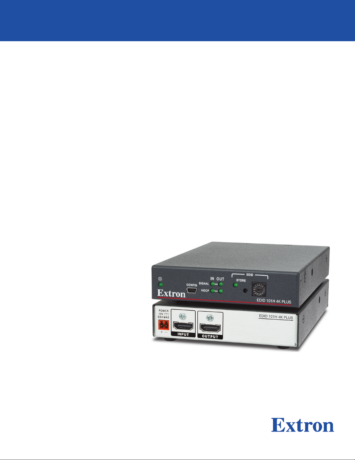
EDID 101H 4K PLUS
HDMI EDID Emulator
User Guide
HDMI
68‑3109‑01 Rev. B
06 20
Page 2

Safety Instructions
Safety Instructions • English
WARNING: This symbol, , when used on the product, is intended to
alert the user of the presence of uninsulated dangerous voltage within
the product’s enclosure that may present a risk of electric shock.
ATTENTION: This symbol, , when used on the product, is intended
to alert the user of important operating and maintenance (servicing)
instructions in the literature provided with the equipment.
For information on safety guidelines, regulatory compliances, EMI/EMF
compatibility, accessibility, and related topics, see the Extron Safety and
Regulatory Compliance Guide, part number 68-290-01, on the Extron
website, www.extron.com.
Sicherheitsanweisungen • Deutsch
WARNUNG: Dieses Symbol auf dem Produkt soll den Benutzer
darauf aufmerksam machen, dass im Inneren des Gehäuses dieses
Produktes gefährliche Spannungen herrschen, die nicht isoliert sind und
die einen elektrischen Schlag verursachen können.
VORSICHT: Dieses Symbol auf dem Produkt soll dem Benutzer in
der im Lieferumfang enthaltenen Dokumentation besonders wichtige
Hinweise zur Bedienung und Wartung (Instandhaltung) geben.
Weitere Informationen über die Sicherheitsrichtlinien, Produkthandhabung,
EMI/EMF-Kompatibilität, Zugänglichkeit und verwandte Themen finden Sie in
den Extron-Richtlinien für Sicherheit und Handhabung (Artikelnummer
68-290-01) auf der Extron-Website, www.extron.com.
Instrucciones de seguridad • Español
Istruzioni di sicurezza • Italiano
AVVERTENZA: Il simbolo, , se usato sul prodotto, serve ad
avvertire l’utente della presenza di tensione non isolata pericolosa
all’interno del contenitore del prodotto che può costituire un rischio di
scosse elettriche.
ATTENTZIONE: Il simbolo, , se usato sul prodotto, serve ad avvertire
l’utente della presenza di importanti istruzioni di funzionamento e
manutenzione nella documentazione fornita con l’apparecchio.
Per informazioni su parametri di sicurezza, conformità alle normative,
compatibilità EMI/EMF, accessibilità e argomenti simili, fare riferimento
alla Guida alla conformità normativa e di sicurezza di Extron, cod. articolo
68-290-01, sul sito web di Extron, www.extron.com.
I
ADVERTENCIA: Este símbolo, , cuando se utiliza en el
producto, avisa al usuario de la presencia de voltaje peligroso sin aislar
dentro del producto, lo que puede representar un riesgo de descarga
eléctrica.
ATENCIÓN: Este símbolo, , cuando se utiliza en el producto,
avisa al usuario de la presencia de importantes instrucciones de uso y
mantenimiento recogidas en la documentación proporcionada con el
equipo.
Para obtener información sobre directrices de seguridad, cumplimiento
de normativas, compatibilidad electromagnética, accesibilidad y temas
relacionados, consulte la Guía de cumplimiento de normativas y seguridad
de Extron, referencia 68-290-01, en el sitio Web de Extron, www.extron.com.
Instructions de sécurité • Français
AVERTISSEMENT : Ce pictogramme, , lorsqu’il est utilisé sur le
produit, signale à l’utilisateur la présence à l’intérieur du boîtier du
produit d’une tension électrique dangereuse susceptible de provoquer
un choc électrique.
ATTENTION : Ce pictogramme, , lorsqu’il est utilisé sur le produit,
signale à l’utilisateur des instructions d’utilisation ou de maintenance
importantes qui se trouvent dans la documentation fournie avec le
matériel.
Pour en savoir plus sur les règles de sécurité, la conformité à la
réglementation, la compatibilité EMI/EMF, l’accessibilité, et autres sujets
connexes, lisez les informations de sécurité et de conformité Extron, réf.
68-290-01, sur le site Extron, www.extron.com.
Page 3
Copyright
© 2020 Extron Electronics. All rights reserved. www.extron.com
Trademarks
All trademarks mentioned in this guide are the properties of their respective owners.
The following registered trademarks (®), registered service marks (SM), and trademarks (TM) are the property of RGBSystems, Inc. or
ExtronElectronics (see the current list of trademarks on the Terms of Use page at www.extron.com):
Registered Trademarks (
®
)
Extron, Cable Cubby, ControlScript, CrossPoint, DTP, eBUS, EDID Manager, EDID Minder, Flat Field, FlexOS, Glitch Free, Global
Configurator, GlobalScripter, GlobalViewer, Hideaway, HyperLane, IPIntercom, IPLink, KeyMinder, LinkLicense, LockIt, MediaLink,
MediaPort, NAV, NetPA, PlenumVault, PoleVault, PowerCage, PURE3, Quantum, ShareLink, Show Me, SoundField, SpeedMount,
SpeedSwitch, StudioStation, SystemINTEGRATOR, TeamWork, TouchLink, V-Lock, VideoLounge, VN-Matrix, VoiceLift, WallVault, WindoWall,
XPA, XTP, XTPSystems, and ZipClip
Registered Service Mark
(SM)
: S3 Service Support Solutions
Trademarks (™
)
AAP, AFL (Accu-RATEFrameLock), ADSP(Advanced Digital Sync Processing), Auto-Image, AVEdge, CableCover, CDRS(ClassD
Ripple Suppression), Codec Connect, DDSP(Digital Display Sync Processing), DMI (DynamicMotionInterpolation), DriverConfigurator,
DSPConfigurator, DSVP(Digital Sync Validation Processing), eLink, EQIP, Everlast, FastBite, Flex55, FOX, FOXBOX, IP Intercom
HelpDesk, MAAP, MicroDigital, Opti-Torque, PendantConnect, ProDSP, QS-FPC(QuickSwitch Front Panel Controller), RoomAgent,
Scope-Trigger, SIS, SimpleInstructionSet, Skew-Free, SpeedNav, Triple-Action Switching, True4K, True8K, Vector™ 4K, WebShare, XTRA,
and ZipCaddy
Page 4

FCC Class A Notice
This equipment has been tested and found to comply with the limits for a Class A digital
device, pursuant to part15 of the FCC rules. The ClassA limits provide reasonable
protection against harmful interference when the equipment is operated in a commercial
environment. This equipment generates, uses, and can radiate radio frequency energy and,
if not installed and used in accordance with the instruction manual, may cause harmful
interference to radio communications. Operation of this equipment in a residential area is
likely to cause interference. This interference must be corrected at the expense of the user.
NOTE: For more information on safety guidelines, regulatory compliances, EMI/EMF
compatibility, accessibility, and related topics, see the Extron Safety and Regulatory
Compliance Guide on the Extron website.
VCCI-A Notice
この装置は、クラスA情報技術装置です。 この装置を家庭環境で使用すると、電波妨害を引き
起こすことがあります。 その場合には使用者が適切な対策を講ずるよう要求されることがあります。
VCCI-A
Page 5

Conventions Used in this Guide
Notifications
The following notifications are used in this guide:
ATTENTION:
• Risk of property damage.
• Risque de dommages matériels.
NOTE: A note draws attention to important information.
Software Commands
Commands are written in the fonts shown here:
^AR Merge Scene,,0p1 scene 1,1 ^B 51 ^W^C.0
[01] R 0004 00300 00400 00800 00600 [02] 35 [17] [03]
E X! *X1&* X2)* X2#* X2! CE}
NOTE: For commands and examples of computer or device responses used in this
guide, the character “0” is the number zero and “O” is the capital letter “o.”
Computer responses and directory paths that do not have variables are written in the font
shown here:
Reply from 208.132.180.48: bytes=32 times=2ms TTL=32
C:\Program Files\Extron
Variables are written in slanted form as shown here:
ping xxx.xxx.xxx.xxx —t
SOH R Data STX Command ETB ETX
Selectable items, such as menu names, menu options, buttons, tabs, and field names are
written in the font shown here:
From the File menu, select New.
Click the OK button.
Specifications Availability
Product specifications are available on the Extron website, www.extron.com.
Extron Glossary of Terms
A glossary of terms is available at http://www.extron.com/technology/glossary.aspx.
Page 6

Page 7

Introduction ...............................................1
About this Guide .................................................. 1
About the EDID101H4K PLUS ........................... 1
EDID101H4K PLUS Features............................. 1
Application Diagram ............................................ 2
Installation and Configuration ................... 3
Installation Overview ............................................ 3
Front Panel Features ............................................ 4
Rear Panel Features and Cabling ......................... 5
Securing the HDMI Connector LockIt Lacing
Bracket .............................................................. 6
EDIDConfiguration .............................................. 7
Assign Extron Factory EDID ............................. 7
Store an EDID in a User Store Slot ................... 7
Configuration Software .............................. 9
Downloading Software from the Extron
Website .............................................................. 9
Installing the Software ........................................ 10
Starting the Software ......................................... 11
Device Discovery Panel .................................. 11
Help Files ....................................................... 12
Offline Device Preview .................................... 12
Using the Software and Device Menus .............. 13
Remote Communication and Control ....... 14
Using Simple Instruction Set (SIS) Commands ... 14
Host-to-device Communications ................... 14
Device-initiated Messages ............................. 14
Error Responses ............................................ 14
Using the Command and Response Table ......... 15
Command and Response Table for SIS
Commands ...................................................... 16
Reference Information ............................. 18
Mounting the EDID101H4K PLUS ................... 18
Desktop Placement ....................................... 18
Rack Mounting .............................................. 18
Connecting to the USB Port .............................. 19
DataViewer ........................................................ 20
Updating the Firmware ...................................... 20
Download and Install Firmware Loader .......... 21
Downloading EDID101H4K PLUS Firmware .... 22
Loading EDID101H4K PLUS Firmware ............ 22
viiTechnical Publications Standards and Styles • Contents
Page 8

Technical Publications Standards and Styles • Contents viii
Page 9

Introduction
This section describes this user guide and the EDID101H4K PLUS, including:
• About this Guide
• About the EDID101H4K PLUS
About this Guide
This guide contains information about the Extron EDID101H4K PLUS with instructions on
how to install, configure, and operate the unit. Throughout this guide, the EDID101H4K
PLUS will be referred to as the “EDID101” as well as “the product.”
About the EDID101H4K PLUS
The Extron EDID101H4K PLUS is a single input, single output HDCP EDID emulator
supporting video rates up to 4K@60 Hz 4:4:4. It supports EDID Minder, HDCP 2.3, and PCS
configuration. You can learn about an individual feature on www.extron.com:
• Understanding EDID - Extended Display Identification Data
• Introduction to HDCP 2.3
• Product Configuration Software (PCS) Page
The EDID101H4K PLUS is housed in a compact one inch tall, quarter rack wide, six
inch deep enclosure for discreet installation (see Mounting the EDID101H4K PLUS on
page18). An energy‑efficient external universal power supply is included.
• EDID101H4K PLUS Features
• Application Diagram
EDID101H4K PLUS Features
• EDID Minder — Automatically manages EDID communication between connected
devices. EDID Minder ensures all sources power up properly, and reliably output content
for display.
• Selectable resolutions and refresh rates — Pre‑stored EDID is communicated to
the source based on a user‑selected resolution and refresh rate.
• EDID capture mode — When connected to a display, the EDID101H4K PLUS offers
the option of capturing and then storing EDID information from the display device.
• Supported HDMI 2.0b specification — Features include data rates up to 18 Gbps,
Deep Color up to 12‑bit, 3D, and CEC pass through.
• Supports multiple embedded audio formats — The EDID 101H 4K PLUS is
compatible with a broad range of multi channel audio signals, providing reliable
operation with HDMI sources.
• Supports computer and video resolutions up to 4K — Resolutions up to
4096x2160 @ 60Hz, 8‑bit, 4:4:4 chroma sampling.
• HDCP compliant — Ensures display of content protected media and interoperability
with other HDCP‑compliant devices.
EDID101H4K PLUS • Introduction 1
Page 10

• HDCP authentication and signal presence confirmation — Provides real‑time
HDCP verification status via front panel LEDs and USB, providing feedback to a system
operator or helpdesk support staff.
• User-selectable HDCP authorization — Indicates if the display is HDCP compliant or
non‑HDCP compliant to the connected source, if the source automatically encrypts all
content when connected to an HDCP‑compliant device.
• Easy setup and commissioning with Extron PCS – Product Configuration
Software – Allows user to configure multiple products using a single software
application.
• HDMI to DVI Interface Format Correction — Automatically reformats HDMI source
signals for output to a connected DVI display.
• Automatic HDMI input cable equalization — Actively conditions incoming HDMI
signals to compensate for signal loss when using long cables, low quality cables, or
source devices with poor signal output.
• Front panel USB configuration port
• Provides 12 VDC, 1 A, 12 watts power on the output for external peripheral
devices.
• Includes LockIt HDMI cable lacing brackets.
• Energy-efficient external universal power supply included — Provides worldwide
compatibility, low power consumption, and reduced operating costs.
Application Diagram
EDID101H4K PLUS • Introduction 2
Page 11

Installation and Configuration
This section describes the installation, and configuration of the EDID 101H 4K PLUS,
including:
• Installation Overview
• Front Panel Features
• Rear Panel Features and Cabling
• Securing the HDMI Connector LockIt Lacing Bracket
• EDIDConfiguration
Installation Overview
To install the EDID 101H 4K PLUS:
1. Mount the EDID 101H 4K PLUS (see Mounting the EDID101H4K PLUS on
page18).
Do not connect power to the source, the display, or the EDID 101H 4K PLUS at this
time.
NOTE: Configure the EDID 101H 4K PLUS prior to the installation if access is
restricted after mounting or installation.
2. Configure the EDID 101H 4K PLUS (see EDIDConfiguration on page7).
3. Connect an HDMI cable from the source to the input connector (see figure2, B on
page5).
4. Connect an HDMI cable from the output connector (C) to the video display or
distribution system input.
5. Connect power and turn on the video display or distribution system.
6. Apply power to the EDID 101H 4K PLUS (A). The LED lights turn on.
7. Turn on the video source.
The video source reads the EDID information from the EDID 101H 4K PLUS.
EDID101H4K PLUS • Installation and Configuration 3
Page 12

EDID101H4K PLUS • Installation and Configuration
Front Panel Features
B
DDD
F
AAA B
B
CONFIG
CCC
SIGNAL
HDCP
IN OUT
EEEF
STORE
F
EDID
0
1
F
EDID 101H 4K PLUSExtron
GGG
3
2
E
4
5
6
7
8
9
A
B
C
D
Figure 1. EDID101H4K PLUS Front Panel Indicators and Configuration Port
Power LED – Lights when an external power supply is connected and powered.
A
Config port – Connect a host computer using a mini USB type‑B connector for
B
configuration using SIS commands or the PCS configuration software, and for firmware
updates (see Connecting to the USB Port on page19).
Signal LEDs – Lights when a HDMI signal is detected on the input and output.
C
HDCP LEDs – The IN LED Lights when the source device requires HDCP encryption
D
and the signal has been authenticated, and the OUT LED lights when HDCP is
authenticated between the HDMI output and the connected sink device. This only
occurs when the source device requires HDCP and is authenticated.
If the source does not require HDCP or if the sink device is not HDCP compliant, the
LED does not light.
EDID Store LED – Lights steadily when power is connected. It blinks when the unit is
E
reading and storing EDID from a connected output device, returning to steady when
recording is complete.
EDID Store button – Press this recessed button to initiate reading and storing an
F
EDID. The EDID is stored to a user slot selected by the rotary switch. Up to four EDID
files can be stored.
Reset – To reset the EDID101H4K PLUS to its default state, press and hold the STORE
button while applying power. As power is applied, all front panel LEDs blink 3 times
indicating a successful reset.
EDID selection rotary switch – One 16‑position rotary switch provides a choice
G
of 12 pre‑programed EDID files and 4 user stored files (see EDIDConfiguration on
page7), and one EDID read from a connected display.
4
Page 13

EDID101H4K PLUS • Installation and Configuration
Rear Panel Features and Cabling
B
C
A
(5 mm) Max.
POWER
0.3A MAX
B
AAA
B
C
C
POWER
12V
0.3A MAX
OUTPUTINPUT
EDID 101H 4K PLUS
Figure 2. EDID101H4K PLUS Rear Panel
Power Connector — Connect the included 12VDC power supply to this two‑pole,
A
3.5mm captive screw connector.
SECTION A–A
Smooth
Ridges
3/16"
A
12V
Figure 3. 12 VDC Power Connection to EDID101H4K PLUS
HDMI input — Connect an HDMI source to this female HDMI connector.
B
HDCP 2.3
— When required, the HDMI input negotiates and authenticates
HDCP 2.3 with a source device. The authentication process is repeated when a
stored EDID is changed (see Securing the HDMI Connector LockIt Lacing
Bracket on page 6).
HDMI output — Connect a display or other output device to this female HDMI
C
connector. The HDMI output provides 12VDC, (up to 1 A with over‑current protection)
on pin 16 (see Securing the HDMI Connector LockIt Lacing Bracket).
HDCP — If a connected output device requires HDCP encryption, the output
negotiates and authenticates HDCP directly.
Video Format Correction — When the current input signal is HDMI and the
connected output is DVI, the signal is converted to DVI format. This is based on the
capability of the connected output device as listed in its EDID.
The EDID information is read from the connected output device and written to memory
whenever the output device is connected to this port and powered on.
NOTE: The EDID information is also read and stored whenever power is recycled to
the connected output device or when the output device is replaced.
5
Page 14

EDID101H4K PLUS • Installation and Configuration
Securing the HDMI Connector LockIt Lacing Bracket
1
Follow these instructions to secure the input connectors to the switcher with the LockIt
HDMI lacing bracket provided:
3
2
Figure 4. LockIt Lacing Bracket Diagram
1. Plug the HDMI cable into the rear panel connection (see figure 4, 1).
2. Loosen the HDMI connection mounting screw from the panel enough to allow the LockIt lacing
bracket to be placed over it
3. Place the LockIt lacing bracket on the screw and against the HDMI connector 3, then tighten
the screw to secure the bracket.
ATTENTION:
• Do not overtighten the HDMI connector mounting screw. The shield it fastens
to is very thin and can easily be stripped.
• Ne serrez pas trop la vis de montage du connecteur HDMI. Le blindage auquel
elle est attachée est très fin et peut facilement être dénudé.
4. Loosely place the included tie wrap around the HDMI connector and the LockIt lacing bracket as
shown
5. While holding the connector securely against the lacing bracket, tighten the tie wrap, then remove
any excess length
4
.
.
5
4
3
5
. The screw does not have to be removed.
2
ATTENTION:
• Always use a power supply provided by or specified by Extron. Use of an
unauthorized power supply voids all regulatory compliance certification and may
cause damage to the supply and the end product.
• Utilisez toujours une source d’alimentation fournie ou recommandée par Extron.
L’utilisation d’une source d’alimentation non autorisée annule toute conformité
réglementaire et peut endommager la source d’alimentation ainsi que le produit
final.
• Unless otherwise stated, the AC/DC adapters are not suitable for use in air
handling spaces or in wall cavities.
• Sauf mention contraire, les adaptateurs AC/DC ne sont pas appropriés pour une
utilisation dans les espaces d’aération ou dans les cavités murales.
• The power supply is to be located within the same vicinity as the Extron AV
processing equipment in an ordinary location, Pollution Degree 2, secured to the
equipment rack within the dedicated closet, podium, or desk.
• La source d’alimentation doit être située à proximité de l’équipement de traitement
audiovisuel dans un endroit ordinaire, avec un degré2 de pollution, fixé à un
équipement de rack à l’intérieur d’un placard, d’une estrade, ou d’un bureau.
6
Page 15

EDID101H4K PLUS • Installation and Configuration
ATTENTION:
EDIDConfiguration
EDID Minder ensures that a connected source has access to the EDID of a display even
if the display is not connected. Depending on the EDID mode selected, the EDID of a
connected display or custom EDID can be stored in one of four user slots, or the user can
manually select an EDID from the table of Extron factory EDID (see figure5 on page8).
TIP: If access to the EDID101H4K PLUS is restricted after mounting and
connection, configure it prior to the installation.
• The installation must always be in accordance with the applicable provisions of
National Electrical Code ANSI/NFPA 70, article 75 and the Canadian Electrical
Code part 1, section 16.
• Cette installation doit toujours être en accord avec les mesures qui s’applique
au National Electrical Code ANSI/NFPA70, article725, et au Canadian Electrical
Code, partie1, section16.
• The power supply shall not be permanently fixed to building structure or similar
structure.
• La source d’alimentation ne devra pas être fixée de façon permanente à une
structure de bâtiment ou à une structure similaire.
• If not provided with a power supply, this product is intended to be supplied by a
power source marked “Class 2” or “LPS” and rated at 12 VDC and a minimum of
0.3 A.
• Si ce produit ne dispose pas de sa propre source d’alimentation électrique, il doit
être alimenté par une source d’alimentation de classe 2 ou LPS et paramétré à 12
V et 0.3 A minimum.
Assign Extron Factory EDID
Rotary switch positions 0 through B are Extron factory EDID. Select a switch position
corresponding to the desired resolution (see figure5).
Additionally, four user slots C through F are available to save the EDID of connected displays
(see Store an EDID in a User Store Slot) and to import EDID files from an external source
with PCS (see Using the Software and Device Menus on page13). EDID saved to
these slots are retained after a power cycle. Upon a factory reset, these EDID slots revert to
the default (1080p @ 60 Hz, 2‑Ch audio). EDID can only be stored via the rotary switch.
Store an EDID in a User Store Slot
To store EDID from a connected display or other sink device:
1. Turn the rotary switch (see figure 5) to the desired user slot location (Cthrough F).
2. Connect the display device to the output connector of the EDID101H4K PLUS (see
figure2, C on page5).
3. Connect a power source and apply power to the EDID101H4K PLUS (see figure2).
The power LED lights steady when power is available.
4. Power on the display device.
7
Page 16
EDID101H4K PLUS • Installation and Configuration
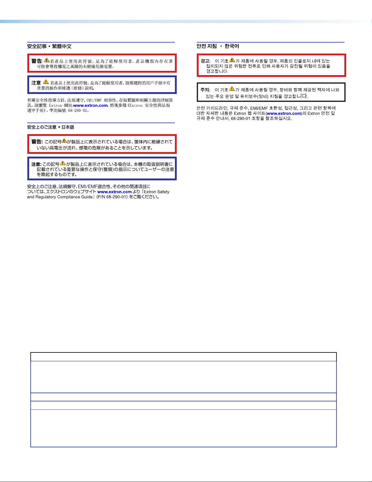
5. Press STORE once to store the display EDID to the memory slot selected in step 1. The
LED blinks. When the LED returns to solid, the EDID is stored (see figure 5).
NOTE: EDID stored in user slots C through F are saved until a new EDID is stored to
that slot or the device is reset.
EDID
STORE
4
5
3
6
7
2
8
1
9
0
A
F
B
E
C
D
EDID 101H 4K PLUS
Figure 5. Store LED, Button and Rotary Switch (in Position E)
X^
Rotary Switch
Position
Native
Resolution
Refresh Rate
Type
Video Format Audio
Format
1 0 1280 x 800 60 Hz IT HDMI 1.3 2‑Ch
2 1 1600 x 900 60 Hz IT HDMI 1.3 2‑Ch
3 2 1920 x 1200 60 Hz IT HDMI 1.3 2‑Ch
4 3 2560 x 1440 60 Hz IT HDMI 1.4 2‑Ch
5 4 2560 x 1600 60 Hz IT HDMI 1.4 2‑Ch
6 5 720p 50 Hz CE HDMI 1.3 2‑Ch
7 6 720p 60 Hz CE HDMI 1.3 2‑Ch
8 7 1080p 50 Hz CE HDMI 1.3 2‑Ch
9 8 1080p 60 Hz CE HDMI 1.3 2‑Ch
10 9 4K / UHD 30 Hz CE HDMI 1.4 2‑Ch
11 A 4K / UHD 4:2:0 60 Hz CE HDMI 1.4 2‑Ch
12 B 4K / UHD 4:4:4 60 Hz CE HDMI 2.0 2‑Ch
13 C Store Slot 1
14 D Store Slot 2
15 E Store Slot 3
16 F Store Slot 4
Table 1. Rotary Switch Position EDID Selection
LED Rotary
Off 0‑B Non‑functional EDID storing is not possible on the selected
Green
(flashing)
Green
(solid)
Table 2. EDID Store LED
NOTE: PCS can be used to import or export EDID from User Store Slots.
Store Button Description
Switch
rotary position.
C‑F Button has been
pressed and
released
The Store button has been pressed and the
EDID is currently being stored to the selected
user store slot.
C‑F N/A EDID storing is possible on the selected rotary
position, or the storing process is complete (if
following the flashing state).
8
Page 17

Configuration
2
3
Software
The Extron Product Configuration Software (PCS) offers another way to configure the EDID
101H 4K PLUS via USB in addition to the SIS commands.
This section describes the software installation and communication. Topics in this section
include:
• Downloading Software from the
Extron Website
• Installing the Software • Using the Software and Device Menus
The graphical interface includes the same functions as those on the device front panel with
additional features that are available only using the software.
The control software is compatible with Microsoft Windows operating systems. The software
program is available on the Extron website.
• Starting the Software
Downloading Software from the Extron Website
Visit www.extron.com to find the latest versions of software and firmware for your product.
If necessary, before updating firmware, download and install Firmware Loader.
Download and install the PCS software for configuring the EDID 101H 4K PLUS.
1. Click the DOWNLOAD tab (see figure6, 1).
The Download page opens.
111
23
2
Figure 6. Software and Firmware Links on the Download Tab
EDID101H4K PLUS • Configuration Software 9
3
Page 18
2. On the Download page:
• Scroll to the bottom of the page to view Recent Updates. If the software is listed,
click directly on that link.
• If the software is not in Recent Updates, click the Software link (see figure6, 2
on the previous page) or the View All Software link at the bottom of the page to
open the Download Center, Software page.
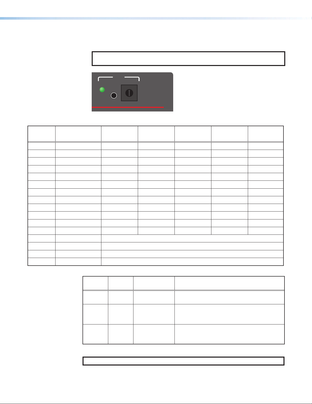
• If there is no direct link to your software, an alphabetic navigation bar is provided
(see figure7). Click the appropriate letter to locate the software or firmware.
Figure 7. Alphabetic Navigation Bar
3. Look at the Release Notes to see the issues that have been addressed by the latest
update.
4. Click Download and follow the Installation Wizard instructions to install the
software on your computer (Login Required).
Installing the Software
The Extron PCS (Product Configuration Software) must be downloaded from the Extron
website to configure the EDID 101H 4K PLUS. To download PCS:
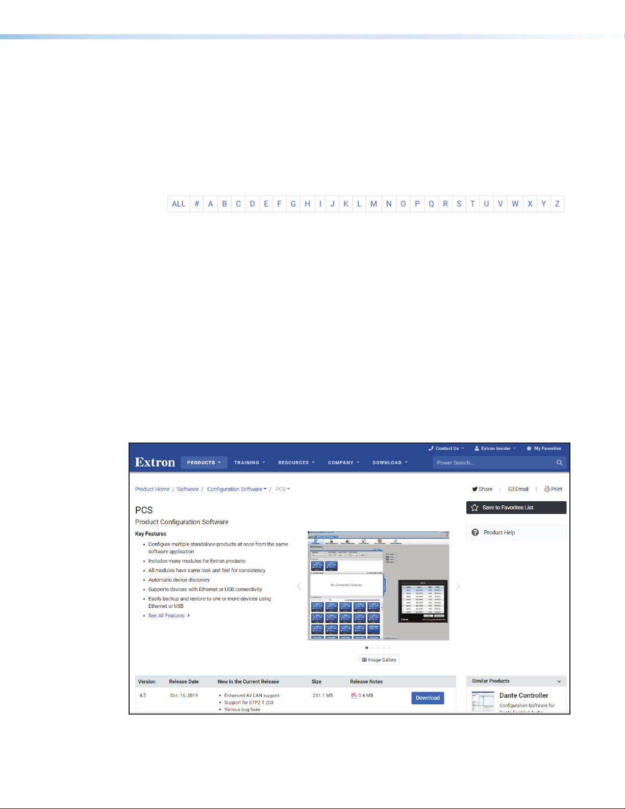
1. On the PCS page, click Download (see figure8, 1).
2. Submit the required information to start the download. Note where the file is saved.
3. Open the executable (.exe) file from the save location.
4. Follow the onscreen instructions. By default, the installation creates a directory in the
Program Files or Program Files (x86) folder.
1
Figure 8. PCS Download from the Extron Website
EDID101H4K PLUS • Configuration Software 10
Page 19

Starting the Software
Open the Extron Product Configuration software program from the Start menu or
desktop shortcut. PCS opens to the Device Discovery page.
NOTES:
• PCS versions prior to 2.0 do not have the Device Discovery feature. Download
the latest version of PCS (see Installing the Software on page10).
• The EDID 101H 4K PLUS supports USB connection only. However, all devices
located and supported by PCS are listed in the Device Discovery panel (see
figure9).
Device Discovery Panel
When the PC running PCS is connected to Extron devices via USB and is also connected to
a LAN or WAN, the Device Discovery panel lists all PCS compatible devices. Devices can
be identified and sorted by Model, IPaddress, Device Name, or Connection method.
Figure 9. Device Discovery Panel
To sort the list of available devices:
1. Click the Device Discovery tab (see figure9, 1).
2. Click the desired column heading (2) to sort the desired category (Model, IP Address,
Device Name and Connection) in ascending or descending order.
To connect to a device:
1. Click the Device Discovery tab (1).
2. Double‑click the EDID 101H 4K PLUS row (3).
A new device configuration tab opens (see figure10 on page12).
or
1. Click the Device Discovery tab (1).
2. Single‑click the row (3) to highlight it.
3. Click Connect (4). A new device configuration tab opens (see figure10).
EDID101H4K PLUS • Configuration Software 11
Page 20
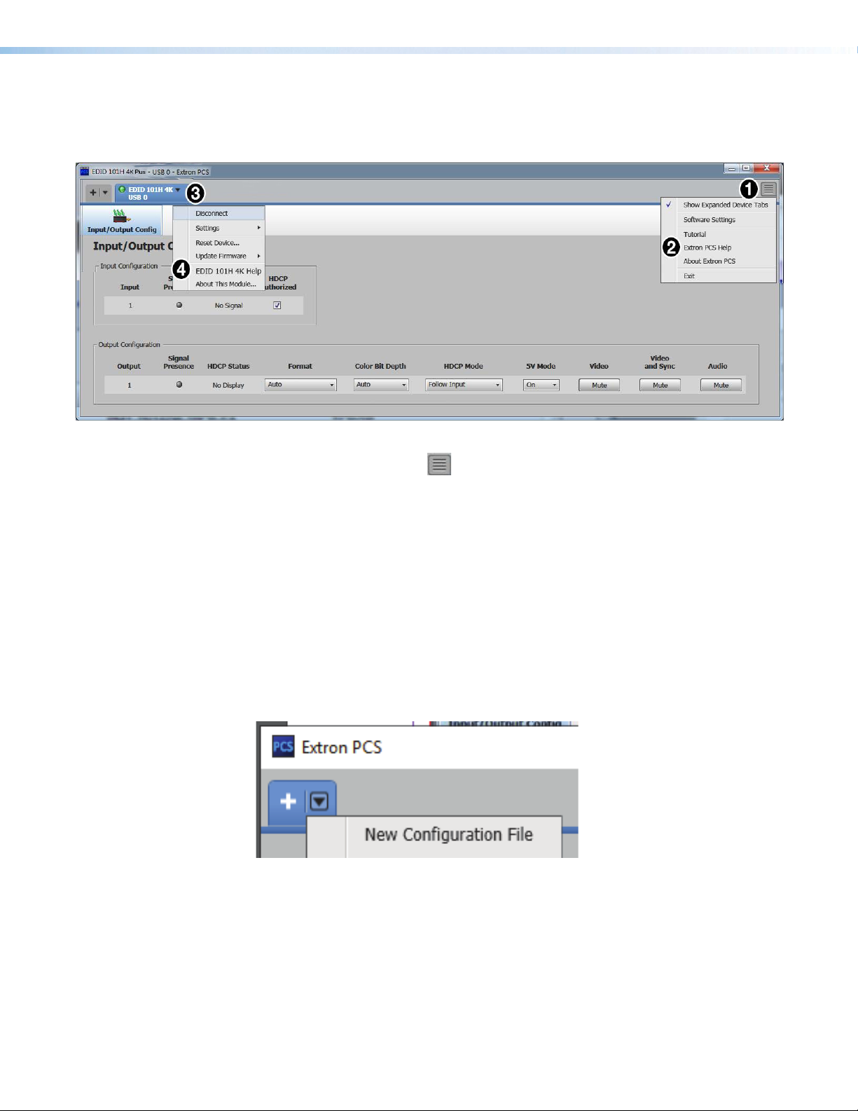
Help Files
When the device page opens, two help files are available; one for the PCS program (see
figure10, 2), and another for the EDID 101H 4K PLUS (4).
Figure 10. PCS and Device Specific Help Files
1. Click the hidden menu icon ( ) to access a drop‑down list (see figure11, 1).
2. Click Extron PCS Help to open the help file (2).
The PCS Help file assists with PCS software operation.
3. Click the Device tab (3)
4. Click EDID 101H 4K PLUS Help (4) to access the EDID 101H 4K PLUS help file for
assistance with the device user interface.
Offline Device Preview
The EDID 101H 4K PLUS configuration options can be viewed without connecting to a
device, but settings cannot be changed or saved.
To open a device tab:
1. In the Start-up tab drop‑down list, select New Configuration File (see figure11).
Figure 11. Configuration Drop-down List
The New Configuration File dialog box opens (see figure12 on the next page).
EDID101H4K PLUS • Configuration Software 12
Page 21
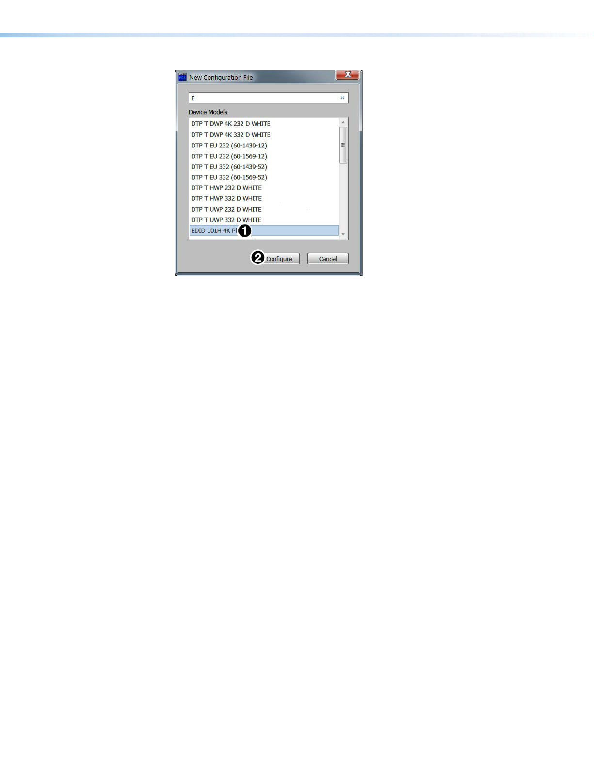
Figure 12. New Configuration File (EDID 101H 4K PLUS Selected)
1. Select the desired device model from the Device Models list (figure12, 1).
2. Click Configure (2). A new offline device configuration tab opens.
See Help Files on page12 for descriptions of the configuration options.
Using the Software and Device Menus
The PCS software provides configuration and operation of the connected device from a
control device. Access the PCS Software Help file or the EDID 101H 4K PLUS Help file for
further information.
EDID101H4K PLUS • Configuration Software 13
Page 22

Remote Communication and Control
This section describes remote operation of the EDID101H4K PLUS. Topics include:
• Using Simple Instruction Set (SIS) Commands
• Using the Command and Response Table
Using Simple Instruction Set (SIS) Commands
The EDID101H4K PLUS is remotely set up and controlled using Extron SIS commands
issued from a host computer or other device, such as a control system. SIS commands are
issued from the connected computer to the front panel Config port (see Connecting to
the USB Port on page19) to connect to this port).
Host-to-device Communications
SIS commands consist of one or more characters per field. No special characters are
required to begin or end a command sequence. You can enter these commands from your
computer using a communication software program such as Extron DataViewer. When
the device determines that a command is valid, it executes the command and sends a
response to the host device.
Most responses from the EDID101H4K PLUS to the host computer end with a carriage
return and a line feed (CR/LF = ]), which signals the end of the response character string.
A string is one or more characters.
Device-initiated Messages
When a local event such as a change in input signal or HDCP status, or a change in the
EDID assignment (changing the front panel rotary switch) takes place, the device responds
by sending a message to the host, indicating the change. No response is required from the
host.
Error Responses
If the device is unable to execute a command it receives because the command is invalid or
contains invalid parameters, the device returns an error response to the host. The following
error response codes can be sent:
E10 – Invalid command
E13 – Invalid value (out of range)
E14 – Not valid for this configuration
E17– Invalid command for signal type
EDID101H4K PLUS • Remote Communications and Control 14
Page 23

Using the Command and Response Table
Space
The command and response table is shown on the following pages. Symbols are used
throughout the table to represent variables in the command and response fields. Symbol
definitions and an ASCII‑to‑hexadecimal (HEX) conversion table are shown below.
Command and response examples are shown throughout the command and response
table.
NOTE: Upper and lower case text can be used interchangeably unless otherwise stated.
ASCII to Hex Conversion Ta ble
Figure 13. ASCII to Hex Conversion Table
Unsolicited Responses
SigX# * X#•HdcpI
EdidAX^
]
X1@
•HdcpO
X1# ]
Broadcast when signal or HDCP status changes on
any input or output
Broadcast when the front panel rotary switch
changes position
•
Common Symbol Definitions
=
]
} or ¦
}
E
|
•
*
CR/LF carriage return with line feed (hex 0D 0A)
=
Carriage return or pipe symbol (no line feed, hex 0D)
=
Carriage return with no line feed (no line feed, hex 0D) (for URL‑encoded commands,
use the pipe character, | , instead)
=
Escape key, or hex 1B (use W instead of E for web browsers, or at any time)
=
Pipe (vertical bar) character (URL equivalent to carriage return)
=
Space
=
Asterisk character (which is a command character, not a variable)
EDID101H4K PLUS • Remote Communications and Control 15
Page 24
Command and Response Table for SIS Commands
NOTE: For commands and examples of computer or device responses used in this guide, the
character “0” is the number zero and “O” is the capital letter “o.”
Command
Signal Status (corresponds to the front panel LED indicators)
Input/Output Signal Status
Input HDCP Status
Output HDCP Status
Video
Video Mute
View Video Mute Status
Input HDCP Authorization
HDCP Authorization Status
Output HDCP Mode
Output HDCP Mode Status
Output TMDS Format
Output TMDS Format Status
Output Color Bit Depth
Output Color Bit Depth
Status
Set Output 5V Mode
Output 5V Mode status
Audio
Disable TMDS Audio Output
Enabled TMDS Audio Output
TMDS Audio Output Status
ASCII Command
(Host to Device)
E
}
0LS
E
E
X@
B Vmt
B
E
E
E
E
E X%
E
E
E
E
E
E
E
E
} X1@ ]
I HDCP
} X1# ]
O HDCP
E X# HDCP
E HDCP
S X$ HDCP
S HDCP
VTPO
V X( BITD
V BITD
X1$
M
M HPLG
O0AFMT
O1AFMT
OAFMT
}
} X# ]
}
} X$ ]
}
VTPO
} X% ]
}
} X( ]
}
HPLG
} X1$ ]
}
}
} X# ]
Response
(Device to Host)
X#
]
* X#
SigX# * X#
]
HdcpIX1@]
HdcpOX1#
]
X@ ]
X@ ]
]
VmtX@
HdcpEX#
HdcpEX#
HdcpSX$
HdcpSX$
VtpoX%
VtpoX%
BitdVX(
BitdVX(
HplgM
HplgM
AfmtO0
AfmtO1
AfmtO
] X#
]
]
]
]
]
]
]
X1$ ]
X1$ ]
]
]
X#]
Additional Description
Input * Output
Verbose Mode 2/3
Verbose Mode 2/3
Verbose Mode 2/3
Verbose Mode 2/3
=1 (enable), default
Verbose Mode 2/3
Verbose Mode 2/3
Verbose Mode 2/3
Verbose Mode 2/3
Verbose Mode 2/3
Verbose Mode 2/3
Default
Verbose Mode 2/3
KEY:
X# = Status 0 = Off, disabled, or undetected 1 = On, enabled, or detected
X$ = Output HDCP Mode:
1 = Encrypt as required by input. Continuous trials for HDMI sinks, attempt for 10s on DVI sinks (then fail) (Default)
2 = Always encrypt. Continuous trials for HDMI sinks, attempt for 10s on DVI sinks (then fail).
2 = DVI RGB 444 Full 5 = HDMI YUV 444 Limited
3 = HDMI RGB 444 Full 6 = HDMI YUV 422 Limited
1= Video detected without HDCP (not encrypted) 4 = HDMI RGB 444 Limited
1= Video detected without HDCP (not encrypted)
1 = Non‑HDCP sink detected
2 = 5V always enabled (default)
X@
= Video mute: 0 = Off (default) 1 = On, video only 2 = Video and Sync
X%
= Output TMDS Format: 1 = Auto (default),HDMI RGB Full if HDMI sink, force DVI format if DVI sink.
X(
= Input HDCP status: 0 = No video detected 2 = Video detected with HDCP (encrypted)
X1@
= Input HDCP status: 0 = No video detected 2 = Video detected with HDCP (encrypted)
X1#
= Output HDCP status: 0 = No active sink detected 2 = HDCP sink detected not encrypted
X1$
= Output 5V Mode: 1 = Auto (5V enabled when source with 5V present, else off)
EDID101H4K PLUS • Remote Communications and Control 16
Page 25

Command
EDID Minder
View EDID assignment
Info/Other
Information
Set Verbose Mode
ASCII Command
(Host to Device)
E
I
} X^ ]
A EDID
EX1)CV}
Response
(Device to Host)
X^ ]
Edid
X#*X#
Sig
HdcpO
Vrb
•HdcpI
X1#]
X1)]
X1@
•
Additional Description
Verbose Mode 2/3
Signal, input HDCP and output HDCP
status
Verbose Mode Status
Set Unit Name
Set Unit Name to Default
View Unit Name
KEY:
X^ = Slot # on EDID lookup table (1‑17) default = 9, (see table1 on page8) Only 1‑16 are addressable by user
1 = verbose mode (default) 3 = verbose mode and tagged responses for queries
The first character must be a letter, and the last character cannot be a hyphen
The default is “EDID‑101H‑4K”
1 = Non‑HDCP sink detected
Query Part Number
Query Model Name
Query Model Description
Query Active Signal
Information
Query Firmware Version
Query Firmware Version with
Build
Reset Setting to Default
X#
= Status 0 = Off, disabled, or undetected 1 = On, enabled, or detected
X1)
= Verbose mode: 0 = clear/none 2 = tagged responses for queries
X1!
= Device name The name is a text string up to 24 alphanumeric characters including hyphens (‑), with no spaces.
X1#
= Output HDCP status: 0 = No active sink detected 2 = HDCP sink detected not encrypted
ECV} X1)]
X1)]
Vrb
E X1!
E
E
N
1I
2I
33 I
Q
*Q n.nn.nnnn
E
}
CN
}
• CN
} X1!]
CN
}
ZXXX
X1! ]
Ipn •
Ipn • EDID-101H-4K-PLUS
60-1680-01
Pno •60-1680-01
EDID-101-4K-PLUS
Inf01*HDMI-101H-4K-PLUS
EDID-101H-4K-PLUS
Inf02*EDID-101H
Emulator
H Active*V Active*V Freq*Pixel Clock
Inf33*H Active*V Active*V Freq*Pixel Clock
n.nn.nnnn
Verbose modes 2 and 3:
Ver01*n.nn
Verbose modes 2 and 3:
Bldn.nn.nnnn
]
Zpx
]
]
]
]
]
]
]
]
Verbose Mode 2/3
]
Verbose Mode 2/3
]
Verbose Mode 2/3
Verbose Mode 2/3
]
]
EDID101H4K PLUS • Remote Communications and Control 17
Page 26

Reference Information
• Mounting the EDID101H4K PLUS
• Connecting to the USB Port
• DataViewer
• Updating the Firmware
Mounting the EDID101H4K PLUS
The one inch high, quarter‑rack width, six inch deep enclosure can be
• Set on a table,
• Mounted on a rack shelf,
• Mounted under a desk or table‑top.
Desktop Placement
Attach the four provided rubber feet to the bottom of the EDID101H4K PLUS, and place it
in any convenient location.
Rack Mounting
UL Guidelines for Rack Mounting
The following Underwriters Laboratories (UL) guidelines are relevant to the safe installation of
these products in a rack:
Elevated operating ambient temperature — If the units are installed in a closed or
multiunit rack assembly, the operating ambient temperature of the rack environment may be
greater than room ambient temperature. Therefore, install the equipment in an environment
compatible with the maximum ambient temperature (Tma: +122 °F, +50 °C) specified by
Extron.
Reduced air flow — Install the equipment in the rack so that the equipment gets adequate
air flow for safe operation.
Mechanical loading — Mount the equipment in the rack so that uneven mechanical
loading does not create a hazardous condition.
Circuit overloading — Connect the equipment to the supply circuit and consider the effect
that circuit overloading might have on overcurrent protection and supply wiring. Consider
the equipment nameplate ratings when addressing this concern.
Reliable earthing (grounding) — Maintain reliable grounding of rack‑mounted equipment.
Pay particular attention to supply connections other than direct connections to the branch
circuit (such as the use of power strips).
EDID101H4K PLUS • Reference Information 18
Page 27
Rack Mounting Procedure
To mount the unit on a rack shelf, follow the instructions provided with the shelf accessories.
Connecting to the USB Port
A female mini type‑B USB Config port located on the front panel (see Front Panel
Features on page4) is used to connect to a host computer for configuration using
SIScommands with Extron DataViewer, for updating firmware with the Extron Firmware
Loader utility and for using PCS.
DataViewer and Firmware Loader are available at www.extron.com. The programs are also
necessary to install the USB driver to the connected computer.
To connect the EDID101H4K PLUS to a host computer:
NOTES:
• If an Extron USB device has never been connected to the host computer, prior to
connecting the Config (USB) port for the first time, you must install and activate
the USB driver. The simplest way to do this is to install either Dataviewer (see
DataViewer on page20) or the Firmware Loader utility (see Updating the
Firmware on page20).
• The wizard opens only on the first occasion you connect the EDID101H4K PLUS
to that USB port. The wizard reopens if you connect the EDID101H4K PLUS to
a different USB port or if you connect a different piece of equipment, requiring a
different driver, to the same USB port.
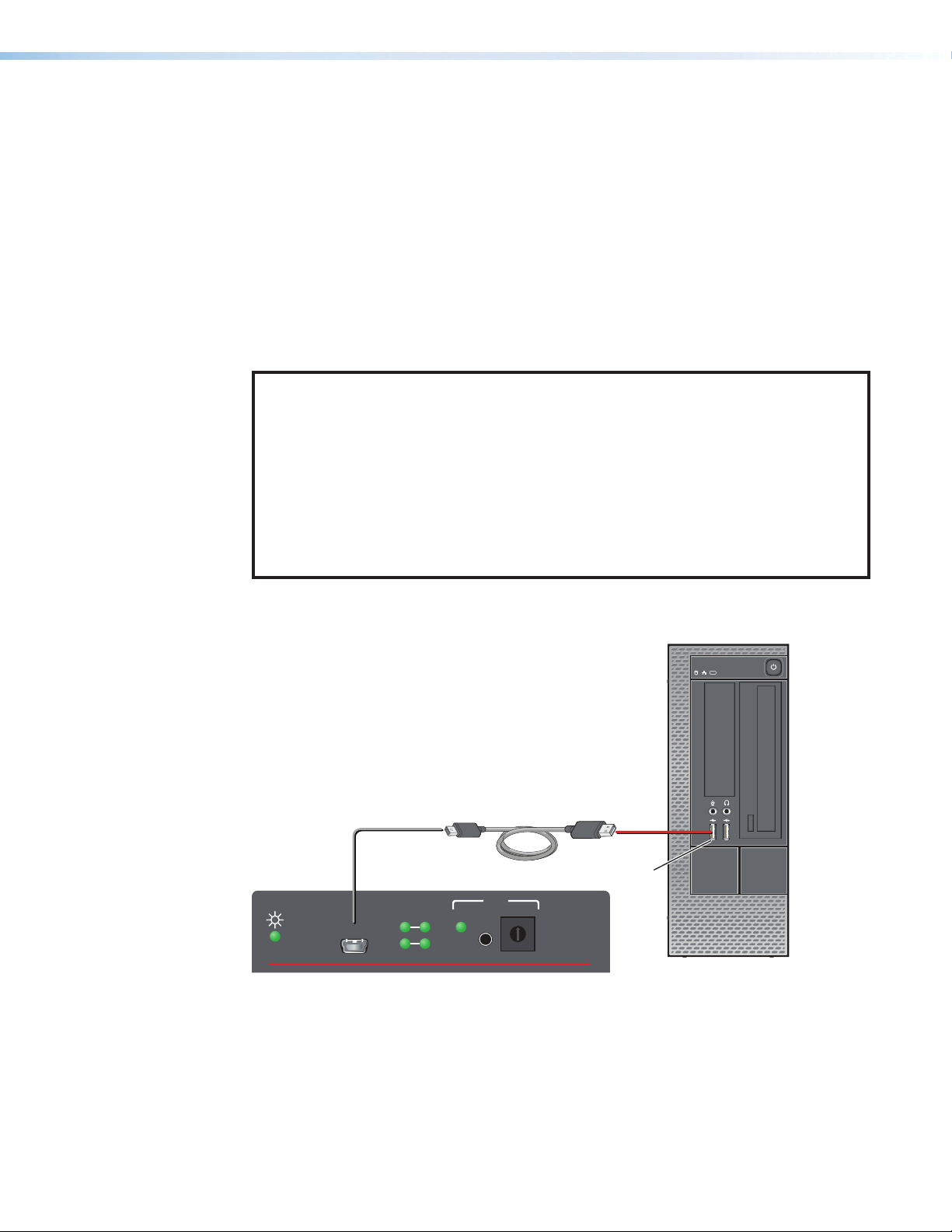
Connect a USB A to mini B cable between the Config port on the front panel of the
EDID101H4K PLUS and a USB port of the PC (see figure14).
WiFi
1 234
CONFIG
SIGNAL
HDCP
IN OUT
Mini Type B
USB
EDID
STORE
USB Cable
4
5
3
6
7
2
1
0
F
B
E
C
D
EDID 101H 4K PLUSExtron
Type A
USB
USB
Ports
8
9
A
Figure 14. Connecting a PC to the Front Panel USB Port
EDID101H4K PLUS • Reference Information 19
Page 28

DataViewer
DataViewer is an enhanced terminal emulation program that facilitates analysis of RS‑232,
USB, and TCP/IP communication with Extron devices. The software allows users to send
commands to a device and view the responses in ASCII or hexadecimal format. Command
and response logs can be saved in text or HTML format.
DataViewer is available at www.extron.com. Enter DataViewer in the search engine to
locate the program.
Download the installation file and load the program on the PC connected to the
EDID101H4K PLUS.
NOTES:
• Only the USB tab is available for the EDID101H4K PLUS.
• If an Extron USB device has never been connected to the host computer,
after installing DataViewer, you must then install and activate the USB driver
Connecting to the USB Port on page19.
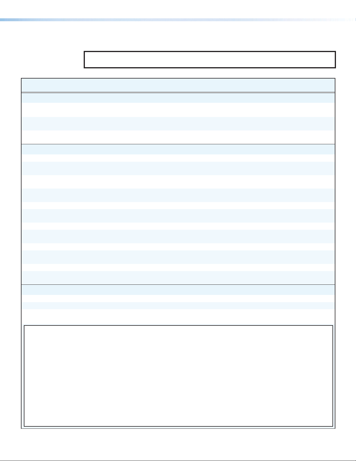
To run DataViewer:
1. Click the DataViewer desktop icon.
2. The Communications Setup dialog box opens (see the image below).
3. Select the USB tab (1).
4. From the USB Port drop‑down list, select Extron USB Device 0 (2).
5. Select the startup option.
6. To automatically connect to the EDID101H4K PLUS, click Connect on Startup (3).
7. Click OK (4) to start using the program.
8. You are now ready to begin entering commands.
Use the DataViewer help file formore information on the program.
Updating the Firmware
Firmware updates are released periodically on the Extron website. You can find the version
currently loaded on your device using SIS commands (see Using the Command and
Response Table on page15). Compare this with the latest release for the EDID101H4K
PLUS on the Extron website and decide whether to update your firmware.
TIP: Read the Release Notes provided on the website with the latest firmware to
determine whether you need the latest version.
This section describes how to update firmware for the EDID101H4K PLUS including:
• Download and Install Firmware Loader
• Downloading EDID101H4K PLUS Firmware
• Loading EDID101H4K PLUS Firmware
EDID101H4K PLUS • Reference Information 20
Page 29

Download and Install Firmware Loader
2
Use the Extron Firmware Loader utility to update the firmware on Extron products. If you do
not already have Firmware Loader installed on your computer, download it as follows:
1. Go to the Extron website at www.extron.com.
2. In the Search field, enter Firmware Loader and press <Enter> (see figure15, 1)
The Firmware Loader page opens.
111
2
2
Figure 15. Firmware Loader Download Link
3. Click Download (2).
4. Follow the instructions on the remainder of the download screens to save the
executable Firmware Loader installer file to your computer. Note the folder to
which the file was saved. By default this is C:\\users\<user name>\Downloads.
5. In your file browser, locate the downloaded executable installer file and double‑click it to
launch the installer.
6. Follow the instructions on the Installation Wizard dialog boxes to install Firmware
Loader on your computer. Unless you specify otherwise, the installer program places
the Firmware Loader File, FWLoader.exe, at c:\Program Files\Extron\FWLoader.
EDID101H4K PLUS • Reference Information 21
Page 30

Downloading EDID101H4K PLUS Firmware
To obtain the latest version of firmware for your device:
1. Go to the Extron website at www.extron.com.
2. Click the DOWNLOAD tab (see figure6, 1 on page9).
3. On the Download page, click the Firmware (2) link.
On the Download Center page, the firmware files are arranged in alphabetical order.
4. In the alphabetical list, click “E.”
5. Locate the EDID101H4K PLUS firmware file row and click Download.
NOTE: Click Release Notes. These notes show the issues addressed by the latest
update. You may decide not to upgrade the firmware.
The Download Center page opens.
6. Enter the requested user information, then click Download.
7. Follow the instructions on the remainder of the download screens to save the
executable firmware file to your computer. Note the folder to which the file was saved.
8. In your file browser, locate the downloaded executable file, and double‑click it.
9. Follow the instructions on the Installation Wizard dialogs to install the new
firmware on your computer. A Release Notes file and a set of instructions for updating
the firmware are also loaded.
Loading EDID101H4K PLUS Firmware
To load a new version of firmware to the device using Firmware Loader, connect your
computer to the front panel USB Configuration port Connecting to the USB Port on
page19.
To access the firmware loader:
To load a new version of firmware to the distribution amplifier using PCS, follow these
instructions.
1. If not already installed, download and install the PCS executable
installer file to the computer (see Downloading EDID101H4K PLUS Firmware on
the previous page).
2. If necessary, download the latest version of firmware for the desired product (see
Updating the Firmware on page20).
3. Connect the distribution amplifier to the computer using the front panel USB connector
(see Front Panel Features on page4).
4. Open Firmware Loader. If there is no desktop icon, open the program from the Start
menu by selecting:
Start > All Programs > Extron Electronics > Extron Product Configuration
Software> Product Configuration Software
The PCS dialog box opens with the Add Device... dialog box in front of it (see
figure16).
EDID101H4K PLUS • Reference Information 22
Page 31

Figure 16. Add Device Dialog Box
5. From the Device Name: drop‑down list, select EDID101H4K PLUS (see figure16, 1
on the previous page).
6. From the Connection Method: drop‑down list, select USB (2).
7. From the Available Devices: drop‑down list, select Extron USB Device_0 (3).
NOTES: Only the Extron USB Device_0 option is available on the AvailableDevices
menu. Make sure that it is selected.
8. Click Connect (4).
The Connected Device panel (5) now displays the device name.
9. Click Browse (6), then locate and open the previously downloaded firmware update
file.
10. Click Add (7).
Themain screen opens with the EDID 101H 4K PLUS high‑lighted (see figure 19 on the
following page).
ATTENTION:
• Valid firmware files must have the file extension S19. A file with any other
extension is not a firmware upgrade for this device and could cause the device to
stop functioning.
• Les fichiers firmware valides doivent contenir l’extension fichier S19. Un fichier avec
n’importe quelle autre extension n’est pas une mise à jour de firmware pour cet
appareil et l’appareil pourrait arrêter de fonctionner.
EDID101H4K PLUS • Reference Information 23
Page 32

Figure 17. Firmware Loader Main Screen
1. Select EDID 101H 4K Plus in the device list and click Begin (see figure17, 1).
The following indicators show the progress of the update:
• The Transfer Time section shows the amounts of remaining and elapsed time for
the update (2).
• The Total Progress section displays a progress bar with Uploading... above it.
• In the Devices section (3):
• Progress column displays an incrementing percentage and another progress
bar.
• Status column displays Uploading.
2. The upload is complete when:
• Remaining Time field shows 00.00.00
• Progress column shows 100%
• Completed is displayed above the progress bar and in the Status field.
3. Close the Firmware Loader software.
4. After uploading the firmware file, the program verifies the file upload was successful.
When the verification is finished, the update is completed.
EDID101H4K PLUS • Reference Information 24
Page 33

Extron Warranty
Extron Electronics warrants this product against defects in materials and workmanship for a period of three years
from the date of purchase. In the event of malfunction during the warranty period attributable directly to faulty
workmanship and/or materials, Extron Electronics will, at its option, repair or replace said products or components,
to whatever extent it shall deem necessary to restore said product to proper operating condition, provided that it is
returned within the warranty period, with proof of purchase and description of malfunction to:
USA, Canada, South America,
and Central America:
Extron Electronics
1230 South Lewis Street
Anaheim, CA 92805
U.S.A.
Europe:
Extron Europe
Hanzeboulevard 10
3825 PH Amersfoort
The Netherlands
Africa:
Extron South Africa
3rd Floor, South Tower
160 Jan Smuts Avenue
Rosebank 2196, South Africa
This Limited Warranty does not apply if the fault has been caused by misuse, improper handling care, electrical
or mechanical abuse, abnormal operating conditions, or if modifications were made to the product that were not
authorized by Extron.
NOTE: If a product is defective, please call Extron and ask for an Application Engineer to receive an RA (Return
Authorization) number. This will begin the repair process.
USA: 714.491.1500 or 800.633.9876 Asia: 65.6383.4400
Europe: 31.33.453.4040 or 800.3987.6673 Japan: 81.3.3511.7655
Africa: 27.11.447.6162 Middle East: 971.4.299.1800
Asia:
Extron Asia Pte Ltd
135 Joo Seng Road, #04-01
PM Industrial Bldg.
Singapore 368363
Singapore
China:
Extron China
686 Ronghua Road
Songjiang District
Shanghai 201611
China
Japan:
Extron Electronics, Japan
Kyodo Building, 16 Ichibancho
Chiyoda-ku, Tokyo 102-0082
Japan
Middle East:
Extron Middle East
Dubai Airport Free Zone
F13, PO Box 293666
United Arab Emirates, Dubai
Units must be returned insured, with shipping charges prepaid. If not insured, you assume the risk of loss or damage
during shipment. Returned units must include the serial number and a description of the problem, as well as the
name of the person to contact in case there are any questions.
Extron Electronics makes no further warranties either expressed or implied with respect to the product and its quality,
performance, merchantability, or fitness for any particular use. In no event will Extron Electronics be liable for direct,
indirect, or consequential damages resulting from any defect in this product even if Extron Electronics has been
advised of such damage.
Please note that laws vary from state to state and country to country, and that some provisions of this warranty may
not apply to you.
Contact Information
Worldwide Headquarters: Extron USA West, 1025 E. Ball Road, Anaheim, CA 92805, 800.633.9876
 Loading...