

Page 1

DXP HD 4K PLUS Series
4K HDMI Switchers
User Guide
Matrix Switchers
68-2939-01 Rev. H
10 20
Page 2

Safety Instructions
Safety Instructions • English
Istruzioni di sicurezza • Italiano
WARNING: This symbol, , when used on the product, is intended to
alert the user of the presence of uninsulated dangerous voltage within
the product’s enclosure that may present a risk of electric shock.
ATTENTION: This symbol, , when used on the product, is intended
to alert the user of important operating and maintenance (servicing)
instructions in the literature provided with the equipment.
For information on safety guidelines, regulatory compliances, EMI/EMF
compatibility, accessibility, and related topics, see the Extron Safety and
Regulatory Compliance Guide, part number 68-290-01, on the Extron
website, www.extron.com.
Sicherheitsanweisungen • Deutsch
WARNUNG: Dieses Symbol auf dem Produkt soll den Benutzer
darauf aufmerksam machen, dass im Inneren des Gehäuses dieses
Produktes gefährliche Spannungen herrschen, die nicht isoliert sind und
die einen elektrischen Schlag verursachen können.
VORSICHT: Dieses Symbol auf dem Produkt soll dem Benutzer in
der im Lieferumfang enthaltenen Dokumentation besonders wichtige
Hinweise zur Bedienung und Wartung (Instandhaltung) geben.
Weitere Informationen über die Sicherheitsrichtlinien, Produkthandhabung,
EMI/EMF-Kompatibilität, Zugänglichkeit und verwandte Themen finden Sie in
den Extron-Richtlinien für Sicherheit und Handhabung (Artikelnummer
68-290-01) auf der Extron-Website, www.extron.com.
Instrucciones de seguridad • Español
AVVERTENZA: Il simbolo, , se usato sul prodotto, serve ad
avvertire l’utente della presenza di tensione non isolata pericolosa
all’interno del contenitore del prodotto che può costituire un rischio di
scosse elettriche.
ATTENTZIONE: Il simbolo, , se usato sul prodotto, serve ad avvertire
l’utente della presenza di importanti istruzioni di funzionamento e
manutenzione nella documentazione fornita con l’apparecchio.
Per informazioni su parametri di sicurezza, conformità alle normative,
compatibilità EMI/EMF, accessibilità e argomenti simili, fare riferimento
alla Guida alla conformità normativa e di sicurezza di Extron, cod. articolo
68-290-01, sul sito web di Extron, www.extron.com.
I
ADVERTENCIA: Este símbolo, , cuando se utiliza en el
producto, avisa al usuario de la presencia de voltaje peligroso sin aislar
dentro del producto, lo que puede representar un riesgo de descarga
eléctrica.
ATENCIÓN: Este símbolo, , cuando se utiliza en el producto,
avisa al usuario de la presencia de importantes instrucciones de uso y
mantenimiento recogidas en la documentación proporcionada con el
equipo.
Para obtener información sobre directrices de seguridad, cumplimiento
de normativas, compatibilidad electromagnética, accesibilidad y temas
relacionados, consulte la Guía de cumplimiento de normativas y seguridad
de Extron, referencia 68-290-01, en el sitio Web de Extron, www.extron.com.
Instructions de sécurité • Français
AVERTISSEMENT : Ce pictogramme, , lorsqu’il est utilisé sur le
produit, signale à l’utilisateur la présence à l’intérieur du boîtier du
produit d’une tension électrique dangereuse susceptible de provoquer
un choc électrique.
ATTENTION : Ce pictogramme, , lorsqu’il est utilisé sur le produit,
signale à l’utilisateur des instructions d’utilisation ou de maintenance
importantes qui se trouvent dans la documentation fournie avec le
matériel.
Pour en savoir plus sur les règles de sécurité, la conformité à la
réglementation, la compatibilité EMI/EMF, l’accessibilité, et autres sujets
connexes, lisez les informations de sécurité et de conformité Extron, réf.
68-290-01, sur le site Extron, www.extron.com.
Page 3

Copyright
© 2018-2020 Extron. All rights reserved. www.extron.com
Trademarks
All trademarks mentioned in this guide are the properties of their respective owners.
The following registered trademarks (®), registered service marks (SM), and trademarks (TM) are the property of RGBSystems, Inc. or Extron
(see the current list of trademarks on the Terms of Use page at www.extron.com):
Registered Trademarks (
®
)
Extron, Cable Cubby, ControlScript, CrossPoint, DTP, eBUS, EDID Manager, EDID Minder, eLink, Flat Field, FlexOS, Glitch Free,
GlobalConfigurator, GlobalScripter, GlobalViewer, Hideaway, HyperLane, IPIntercom, IPLink, KeyMinder, LinkLicense, LockIt,
MediaLink, MediaPort, NAV, NetPA, PlenumVault, PoleVault, PowerCage, PURE3, Quantum, ShareLink, Show Me, SoundField,
SpeedMount, SpeedSwitch, StudioStation, SystemINTEGRATOR, TeamWork, TouchLink, V-Lock, VideoLounge, VN-Matrix, VoiceLift,
WallVault, WindoWall, XPA, XTP, XTPSystems, and ZipClip
Registered Service Mark
(SM)
: S3 Service Support Solutions
Trademarks (™
)
AAP, AFL (Accu-RATEFrameLock), ADSP(Advanced Digital Sync Processing), Auto-Image, AVEdge, CableCover, CDRS(ClassD
Ripple Suppression), Codec Connect, DDSP(Digital Display Sync Processing), DMI (DynamicMotionInterpolation), DriverConfigurator,
DSPConfigurator, DSVP(Digital Sync Validation Processing), EQIP, Everlast, FastBite, Flex55, FOX, FOXBOX, IP Intercom HelpDesk,
MAAP, MicroDigital, Opti-Torque, PendantConnect, ProDSP, QS-FPC(QuickSwitch Front Panel Controller), RoomAgent, Scope-Trigger,
SIS, SimpleInstructionSet, Skew-Free, SpeedNav, Triple-Action Switching, True4K, True8K, Vector™ 4K, WebShare, XTRA, and ZipCaddy
Page 4

FCC Class A Notice
This equipment has been tested and found to comply with the limits for a Class A digital
device, pursuant to part15 of the FCC rules. The ClassA limits provide reasonable
protection against harmful interference when the equipment is operated in a commercial
environment. This equipment generates, uses, and can radiate radio frequency energy and,
if not installed and used in accordance with the instruction manual, may cause harmful
interference to radio communications. Operation of this equipment in a residential area is
likely to cause interference. This interference must be corrected at the expense of the user.
NOTE: For more information on safety guidelines, regulatory compliances, EMI/EMF
compatibility, accessibility, and related topics, see the Extron Safety and Regulatory
Compliance Guide on the Extron website.
VCCI-A Notice
この装置は、クラスA情報技術装置です。 この装置を家庭環境で使用すると、電波妨害を引き
起こすことがあります。 その場合には使用者が適切な対策を講ずるよう要求されることがあります。
VCCI-A
Battery Notice
This product contains a battery. Do not open the unit to replace the battery. If the
battery needs replacing, return the entire unit to Extron (for the correct address, see the
Extron Warranty section on the last page of this guide).
CAUTION: Risk of explosion. Do not replace the battery with an incorrect type. Dispose
of used batteries according to the instructions.
ATTENTION : Risque d’explosion. Ne pas remplacer la pile par le mauvais type de
pile. Débarrassez-vous des piles usagées selon le mode d’emploi.
Page 5

Conventions Used in this Guide
Notifications
The following notifications are used in this guide:
WARNING: Potential risk of severe injury or death.
AVERTISSEMENT : Risque potentiel de blessure grave ou de mort.
CAUTION: Risk of minor personal injury.
ATTENTION : Risque de blessuremineure.
ATTENTION:
• Risk of property damage.
• Risque de dommages matériels.
NOTE: A note draws attention to important information.
Software Commands
Commands are written in the fonts shown here:
^AR Merge Scene,,0p1 scene 1,1 ^B 51 ^W^C.0
[01] R 0004 00300 00400 00800 00600 [02] 35 [17] [03]
E X! *X1&* X2)* X2#* X2! CE}
NOTE: For commands and examples of computer or device responses used in this
guide, the character “0” is the number zero and “O” is the capital letter “o.”
Computer responses and directory paths that do not have variables are written in the font
shown here:
Variables are written in slanted form as shown here:
Selectable items, such as menu names, menu options, buttons, tabs, and field names are
written in the font shown here:
Specifications Availability
Product specifications are available on the Extron website, www.extron.com.
Extron Glossary of Terms
A glossary of terms is available at http://www.extron.com/technology/glossary.aspx.
Reply from 208.132.180.48: bytes=32 times=2ms TTL=32
C:\Program Files\Extron
ping xxx.xxx.xxx.xxx —t
SOH R Data STX Command ETB ETX
From the File menu, select New.
Click the OK button.
Page 6

Page 7

Contents
Introduction............................................................ 1
About this Guide ................................................. 1
About the DXP HD 4K PLUS Series Matrix
Switchers .......................................................... 1
Features ............................................................. 2
EDID Minder ....................................................... 4
Managing EDID............................................... 4
Factory Loaded EDID .................................... 4
Assigned Output EDID .................................... 4
Application Diagrams .......................................... 8
Installation ............................................................ 10
Rear Panels ...................................................... 10
DXP 168 and 1616 PLUS Rear Panel ........... 11
DXP 44, 84, and 88 PLUS Rear Panel .......... 11
DXP 42 PLUS Rear Panel ............................. 11
Legend for Figures 4, 5, and 6 ...................... 11
Rear Panel Features ..................................... 12
Connecting to the LAN Port .............................. 14
Connecting to the Remote RS-232 Port ........... 15
Connecting Power to the
DXP 42 HD 4K PLUS ...................................... 16
Securing the HDMI Connectors Using the
LockIt HDMI Cable Lacing Bracket .................. 18
Operation .............................................................. 19
Definitions ......................................................... 19
Front Panel Controls and Indicators .................. 20
Front Panel Buttons and LEDs ...................... 20
DXP 168 and 1616 HD 4K PLUS Front
Panel ........................................................... 21
DXP 44, 84, and 88 HD 4K PLUS Front
Panel ........................................................... 21
DXP 42 HD 4K PLUS Front Panel ................. 21
Front Panel Features ..................................... 22
Powering On .................................................... 25
Self-test ........................................................ 25
Creating or Changing a Configuration ............... 26
DXP 168 and 1616 PLUS Configuration ....... 27
DXP 44, 84, and 88 PLUS Configuration ...... 28
Creating Ties — DXP 168 and 1616 PLUS ... 29
Creating Ties —
DXP 44, 84, and 88 PLUS ........................... 36
Creating Ties — DXP 42 PLUS ..................... 40
Saving and Recalling Presets ........................... 42
Saving a Preset —
DXP 168 and 1616 PLUS ............................ 42
Saving a Preset —
DXP 44, 84, and 88 PLUS ........................... 44
Muting and Unmuting Outputs from the Front
Panel ............................................................... 46
Muting Outputs —
DXP 168 and 1616 PLUS ............................ 46
Muting Outputs —
DXP 44, 84, and 88 PLUS ........................... 48
Locking and Unlocking the Front Panel
(Executive Modes) ........................................... 49
Setting Lock Modes —
DXP 168 and 1616 PLUS ............................ 50
Setting Lock Modes —
DXP 44, 84, and 88 PLUS ........................... 51
Power Save Modes .......................................... 53
Selecting the Remote RS-232 Port Baud
Rate ................................................................ 53
Selecting the Baud Rate for
DXP 168 and 1616 PLUS ............................ 53
Selecting the Baud Rate for DXP 44, 84, and
88 PLUS ...................................................... 54
Setting the Button Background Illumination —
DXP 168 and 1616 PLUS Only ........................ 55
Resetting .......................................................... 55
Resetting the System from the Front Panel ... 55
Resetting Using the Front or Rear Panel
Reset Button ............................................... 57
Troubleshooting ................................................ 59
DXP HD 4K PLUS Series • Contents
vii
Page 8

Configuration Worksheets................................. 60
Worksheet Example 1: System
Equipment — 8 Inputs and Outputs ............ 60
Worksheet Example 2: Daily
Configuration — 8 Inputs and Outputs ........ 61
Worksheet Example 3: Test
Configuration — 8 Inputs and Outputs ........ 61
Worksheet Example 1: System
Equipment — 16 Inputs and Outputs .......... 62
Worksheet Example 2: Daily
Configuration — 16 Inputs and Outputs ...... 63
Worksheet Example 3: Test Configuration ..... 63
Worksheet Form — 8 Inputs and Outputs ..... 64
Worksheet Form — 16 Inputs and Outputs ... 65
SIS Configuration and Control ........................ 66
Connection Methods ........................................ 66
Host and Matrix Switcher Communication ........ 66
Copyright Information ................................... 66
Device-Initiated Messages ............................ 67
Error Responses ........................................... 68
Connection Timeouts ................................... 68
Number of Connections ................................ 68
SIS Overview .................................................... 69
Using the Command and Response
Tables .......................................................... 69
Verbose Mode .............................................. 69
Symbol Definitions ........................................ 70
Command and Response Table —
DXP 44, 84, 88, 168, and 1616 PLUS ............. 75
Command and Response Table — DXP 42 ...... 91
CEC SIS Commands ..................................... 102
CEC Symbol Definitions .............................. 102
Internal Web Page ............................................ 114
Web Page Access .......................................... 114
Web Page Components ................................. 115
Device Info Panel ........................................ 116
Inputs Panel................................................ 116
RS-232 Panel ............................................. 117
Device Status Panel .................................... 117
Outputs Panel ............................................. 119
Roles and Permissions Panel ...................... 119
Network Settings Panel .............................. 121
Firmware Panel ........................................... 122
Reference Information .................................... 123
Mounting the Switcher .................................... 123
UL Guidelines for Rack Mounting ................ 123
Mounting Procedures ................................. 124
Downloading Updated Firmware ..................... 125
Network Setup ............................................... 126
What is an IP Address?............................... 126
Choosing IP Addresses .............................. 127
Subnet Mask .............................................. 127
Pinging for the IP Address .......................... 128
Connecting as a Telnet Client ...................... 129
Subnetting, a Primer ................................... 131
Configuration Software ................................... 106
Software Installation........................................ 106
Software Download Center Page ................ 106
PCS Product Page ..................................... 108
Software Connection ...................................... 109
Device Discovery Panel ............................... 109
TCP/IP Panel .............................................. 111
Offline Device Preview ................................. 112
Help File Access ............................................. 113
DXP HD 4K PLUS Series • Contents viii
Page 9

Introduction
This section gives an overview of the Extron DXP HD 4K PLUS matrix switchers, describes
significant features of the series, and provides application diagrams. Topics in this section
include:
• About this Guide
• About the DXP HD 4K PLUS Series Matrix Switchers
• Features
• EDID Minder
• Application Diagrams
About this Guide
This guide contains installation, configuration, and operating information for the
DXP HD 4K PLUS Series matrix switchers. In this guide, the terms “DXP PLUS,”
“switcher,” and “DXP PLUS matrix switcher” are used interchangeably to refer to any or all
DXP HD 4K PLUS Series models.
About the DXP HD 4K PLUS Series Matrix Switchers
The DXP HD 4K PLUS Series are high performance HDMI matrix switchers for computer
and video resolutions up to 4K @ 60 Hz. They support HDMI 2.0b specifications, including
data rates up to 18 Gbps, HDR Deep Color up to 12-bit, 3D, and HD lossless audio
formats. These switchers are HDCP 2.3 compliant and incorporate Extron technologies
including SpeedSwitch, EDID Minder, and Key Minder. HDMI input equalization and output
regeneration ensure reliable system operation. Digital audio can be de-embedded from any
input and assigned to digital or analog stereo outputs. The following models are available in
fixed matrix sizes:
• DXP 42 HD 4K PLUS — 4 inputs by 2 outputs with 2 audio outputs
• DXP 44 HD 4K PLUS — 4 inputs by 4 outputs with 2 audio outputs
• DXP 84 HD 4K PLUS — 8 inputs by 4 outputs with 2 audio outputs
• DXP 88 HD 4K PLUS — 8 inputs by 8 outputs with 2 audio outputs
• DXP 168 HD 4K PLUS — 16 inputs by 8 outputs with 4 audio outputs
• DXP 1616 HD 4K PLUS — 16 inputs by 16 outputs with 4 audio outputs
The DXP HD 4K PLUS Series are designed for use with computers equipped with 4K
graphics cards, media players and similar signal sources, and 4K native resolution displays.
With a maximum data rate of 18 Gbps, the switchers support computer and video
resolutions up to 4096x2160 @ 60 Hz with 8-bit color in 4:4:4 color space.
To maintain signal integrity, these switchers feature automatic cable equalization on inputs
and output reclocking to reshape and restore timing of the video signal at each HDMI
output. These features combined with Extron Pro Series High Speed HDMI Cables allow
longer 4K signal runs, reducing the need for additional signal conditioning equipment
by compensating for weak source signals or signal loss on long cable runs. Additionally,
+5 VDC, 250 mA power is available on the outputs for peripheral devices.
DXP HD 4K PLUS Series • Introduction 1
Page 10

Features
• Supports computer and video resolutions up to and including 4K, including
1080p @ 60 Hz Deep Color.
• Supports HDMI 2.0b specification features, including data rates up to 18 Gbps,
Deep Color up to 12-bit, 3D, and HD lossless audio formats.
• HDMI audio de-embedding with digital S/PDIF (Sony/Philips Digital Interface)
and analog stereo audio outputs (DXP 44, 84, 88, 168, and 1616 PLUS only) —
The DXP HD 4K PLUS Series can extract embedded HDMI two-channel LPCM audio
to S/PDIF digital and analog audio outputs. It can also extract Dolby® or DTS® encoded
bitstream audio to the S/PDIF outputs. The matrix switchers feature multiple sets of S/
PDIF and analog outputs, supporting audio assignment from any HDMI input source.
• S/PDIF audio output (DXP 44, 84, 88, 168, and 1616 PLUS only) — The
DXP HD 4K PLUS Series includes S/PDIF outputs for 2-channel LPCM audio or
encoded standard definition bitstream audio for Dolby or DTS multi-channel surround
sound.
• DXP 44, 84, and 88 PLUS have two S/PDF connectors.
• DXP 168 and 1616 PLUS have four S/PDIF connectors.
• HDCP 2.3 compliant — Ensures display of content-protected media and
interoperability with other HDCP-compliant devices.
• Consumer Electronics Control (CEC) capability — Standard, built-in CEC
commands can be triggered to control displays or other AV devices connected
over HDMI. The ability to control specific functions, such as power on and off,
input selection, and volume level are dependent on implementation by the device
manufacturer.
• User-selectable HDCP authorization — Allows individual inputs to appear HDCP
compliant or non-HDCP compliant to the connected source, which is beneficial if the
source automatically encrypts all content when connected to an HDCP-compliant
device. Protected material is not passed in non-HDCP mode.
• SpeedSwitch Technology provides high switching speed for HDCP-encrypted
content.
• Key Minder continuously verifies HDCP compliance for quick, reliable
switching — Key Minder authenticates and maintains continuous HDCP encryption
between input and output devices to ensure quick and reliable switching in professional
AV environments, while enabling simultaneous distribution of a single source to one or
more displays.
• HDCP authentication and signal presence LED indicators — Front panel LED
indicators for signal presence and HDCP authentication provide real time feedback and
monitoring of key performance parameters.
• EDID Minder automatically manages EDID communication between connected
devices — EDID Minder ensures that all sources power up properly and reliably output
content for display (available through Product Configuration Software [PCS]).
• Support for High Dynamic Range video (HDR) — Enables greater contrast range
and wider color gamut by providing the necessary video bandwidth, color depth, and
metadata interchange capability for HDR video.
• Supports DDC transmissions
• HDMI to DVI Interface Format Correction — Automatically reformats HDMI source
signals for output to a connected DVI display.
DXP HD 4K PLUS Series • Introduction 2
Page 11

• Automatic input cable equalization — Equalizes inputs to support signals up to 4K
resolution at greater distances.
• Automatic output reclocking — Reshapes and restores timing of HDMI signals at
each output, enabling transmission over long HDMI cables.
• Provides +5 VDC, 250 mA power on the HDMI outputs for external peripheral
devices
• Global presets (DXP 44, 84, 88, 168, and 1616 PLUS only) — Up to 16
(DXP 88 PLUS series) or 32 (DXP 1616 PLUS series) frequently used I/O configurations
can be saved and recalled using the front panel buttons, Ethernet, USB, or serial
control. This time-saving feature allows I/O configurations to be set up and stored in
memory for future use.
• Rooming (DXP 44, 84, 88, 168, and 1616 PLUS only) — The DXP HD 4K 44, 84,
88, 168, and 1616 PLUS models can be programmed to group selected outputs into
specific “rooms,” each with its own set of unique presets. Each room can support up to
16 outputs. A total of 10 rooms, with 10 presets per room, are available.
• QS-FPC QuickSwitch Front Panel Controller — Discrete buttons for each input and
output allow for simple, intuitive operation.
• View I/O mode — Discrete LEDs for each input button allow easy viewing of actively
connected inputs and outputs for ease in troubleshooting.
• Output volume control — Provides the capability to mute one or all outputs at
any time. This allows, for example, content to be viewed on a local monitor prior to
appearing on the main presentation display.
• Audio breakaway (DXP 44, 84, 88, 168, and 1616 PLUS only) — Provides the
capability to break an analog audio signal away from its corresponding video signal and
route it to the audio outputs, allowing the analog audio channels to be operated as a
separate switcher.
• Ethernet monitoring and control — Can be monitored, managed, or controlled over
a LAN, WAN, or the Internet using standard TCP/IP protocols.
• RS-232 control port — The matrix switcher can be integrated into a control system.
Extron products use the SIS (Simple Instruction Set) command protocol, a set of basic
ASCII code commands that allow for quick and easy programming.
• Product Configuration Software (PCS) — The Extron PCS program provides a
means of configuring multiple products using a single software application.
• Front panel USB configuration port — Enables setup, configuration, and firmware
updating without having to access the rear panel.
• Front panel security lockout (executive mode) — Prevents unauthorized use in
non-secure environments.
• Rack-mountable full rack width metal enclosure, with a height of 1 inch
(DXP 42 PLUS) 1U (DXP 44, 84, and 88) or 2U (DXP 168 and 1616 PLUS)
• Includes Lockit HDMI cable lacing brackets — Secure HDMI cables to the HDMI
connectors.
• Power save mode (DXP 44, 84, 88, 168, and 1616 PLUS only) — The unit can be
placed in a low power standby state to conserve energy when not in use.
• Highly reliable, energy-efficient internal universal power supply — Provides
worldwide power compatibility, with high demonstrated reliability and low power
consumption for reduced operating costs.
DXP HD 4K PLUS Series • Introduction 3
Page 12

EDID Minder
Managing EDID
Factory Loaded EDID
EDID Minder ensures that each source connected to an input sees the EDID of a display,
even when that source is not selected for a display.
Depending on the selected EDID mode, the DXP PLUS can store the EDID of the connected
display automatically (default), or you can manually select a factory EDID file from a predetermined list. This EDID file is written to a file located at each selected input within the
supported video group. All inputs support unique EDID emulation, HDCP, and HDCP
Authorization enabling or disabling.
You can manage EDID files using PCS (see the DXP HD 4K PLUS Series Help file). You
can also select and import EDID files using SIS commands (see the EDID Commands on
page93). (EDID cannot be managed via the front panel.)
The factory loaded EDID stored on the unit are taken from the Extron EDID Standards
Folder, which is created on the DXP PLUS by PCS. You can choose an EDID file from the
folder link via PCS or SIS commands. The HDMI inputs support digital Extron EDID files that
are 2 blocks or 256 bytes. The second block contains audio information. The HDMI EDID
support 2-channel PCM audio. The default Extron factory EDID file 1080p @ 60 Hz.
Assigned Output EDID
The DXP PLUS has four or eight memory slots, depending on the model, for the EDID of the
display connected to the output of the matrix switcher.
The unit automatically saves EDID information from the HDMI outputs whenever an output is
connected. The EDID information is saved until a new display or device is detected, and the
new EDID information overwrites the previous one. The EDID of each output is saved and
made available to any input slot. Assigned output EDID can be directly assigned to any input
via PCS.
DXP HD 4K PLUS Series • Introduction 4
Page 13

EDID tables for DXP HD 4K PLUS
DXP 1616 PLUS (16 x 16) HD 4K PLUS and DXP 168 (16 x 8) HD 4K PLUS
SIS Variable
X5@
1
2
3
4
5
6
7
8
9
10
11
12
13
14
15
16
17
18
19
20
21
22
23
24
25
26
27
28
29
30
31
32
EDID Memory
Slot
Input 1 (Store) EXN_HDMI_1080p60_2Ch.bin Manually populated using PCS
Input 2 (Store)
Input 3 (Store)
Input 4 (Store)
Input 5 (Store)
Input 6 (Store)
Input 7 (Store)
Input 8 (Store)
Input 9 (Store)
Input 10 (Store)
Input 11 (Store)
Input 12 (Store)
Input 13 (Store)
Input 14 (Store)
Input 15 (Store)
Input 16 (Store)
Output 1 N/A Automatically populated with
Output 2
Output 3
Output 4
Output 5
Output 6
Output 7
Output 8
Output 9
Output 10
Output 11
Output 12
Output 13
Output 14
Output 15
Output 16
Default EDID File Details
the sink EDID from the output
DXP HD 4K PLUS Series • Introduction 5
Page 14

DXP 88 HD 4K PLUS (8 x 8) and DXP 84 HD 4K PLUS (8 x 4)
SIS Variable
X5@
1 Input 1 (store) EXN_HDMI_1080p60_2Ch.bin Manually populated via PCS
2 Input 2 (store) EXN_HDMI_1080p60_2Ch.bin Manually populated via PCS
3 Input 3 (store) EXN_HDMI_1080p60_2Ch.bin Manually populated via PCS
4 Input 4 (store) EXN_HDMI_1080p60_2Ch.bin Manually populated via PCS
5 Input 5 (store) EXN_HDMI_1080p60_2Ch.bin Manually populated via PCS
6 Input 6 (store) EXN_HDMI_1080p60_2Ch.bin Manually populated via PCS
7 Input 7 (store) EXN_HDMI_1080p60_2Ch.bin Manually populated via PCS
8 Input 8 (store) EXN_HDMI_1080p60_2Ch.bin Manually populated via PCS
9 Output 1 N/A Automatically populated with
10 Output 2 N/A Automatically populated with
11 Output 3 N/A Automatically populated with
12 Output 4 N/A Automatically populated with
13 Output 5 N/A Automatically populated with
14 Output 6 N/A Automatically populated with
15 Output 7 N/A Automatically populated with
16 Output 8 N/A Automatically populated with
EDID Memory Slot Default EDID File Details
sink EDID from output 1
sink EDID from output 2
sink EDID from output 3
sink EDID from output 4
sink EDID from output 5
sink EDID from output 6
sink EDID from output 7
sink EDID from output 8
DXP HD 4K PLUS Series • Introduction 6
Page 15

DXP 44 HD 4K PLUS (4 x 4)
SIS Variable
X5@
1 Input 1 (store) EXN_HDMI_1080p60_2Ch.bin Manually populated via PCS
2 Input 2 (store) EXN_HDMI_1080p60_2Ch.bin Manually populated via PCS
3 Input 3 (store) EXN_HDMI_1080p60_2Ch.bin Manually populated via PCS
4 Input 4 (store) EXN_HDMI_1080p60_2Ch.bin Manually populated via PCS
5 Output 1 N/A Automatically populated with
6 Output 2 N/A Automatically populated with
7 Output 3 N/A Automatically populated with
8 Output 4 N/A Automatically populated with
DXP 42 HD 4K PLUS (4 x 2)
SIS Variable
X5@
1 Input 1 (store) EXN_HDMI_1080p60_2Ch.bin Manually populated via PCS
2 Input 2 (store) EXN_HDMI_1080p60_2Ch.bin Manually populated via PCS
3 Input 3 (store) EXN_HDMI_1080p60_2Ch.bin Manually populated via PCS
4 Input 4 (store) EXN_HDMI_1080p60_2Ch.bin Manually populated via PCS
5 Output 1 N/A Automatically populated with
6 Output 2 N/A Automatically populated with
EDID Memory Slot Default EDID File Details
EDID Memory Slot Default EDID File Details
sink EDID from output 1
sink EDID from output 2
sink EDID from output 3
sink EDID from output 4
sink EDID from output 1
sink EDID from output 2
DXP HD 4K PLUS Series • Introduction 7
Page 16

Application Diagrams
STATUS
INPUTS
REMOTE
REMOTE
Lorem ipsum
Lorem ipsum
Lorem ipsum
Lorem ipsum
Wireless Access Point
Smartphone
Tabl et
CONFIG
SIGNAL
HDMI
HDMI
WINDOW
PASS-THROUGH
STANDBY
HDCP
SCREEN
OUTPUTINPUT
HDMI DECODER
HD WIN
Extron
ShareLink Pro 1000
Wireless and Wired
Collaboration Gateway
Logitech
Rally Camera
USB
12 3 4
WiFi
Videoconferencing PC
Ethernet
Laptop
1 2
HD PASS
DECODER
Ethernet
USB
ShareLink Pro 1000
LAN
Ethernet
HDMI
USB
Laptop Laptop
HDMIHDMI
POWER
12V
1.5A MAX
1
HDMI
INPUTS
2
HDMI3HDMI4HDMI
Shure MXA310
Tabl e Mic
HDMI
Capture
1
HDMI/CEC
OUTPUTS
HDMIHDMI
2
HDMI/CEC
HDMI
L3R L4R
AUDIO OUTPUTS
REMOTE
RS-232
Tx
Rx G
Ethernet
Ethernet
4K Display
MODEL 80
Extron
SB 33 A
Sound Bar
Extron
LAN
DXP 42 HD 4K PLUS
4K/60 HDMI Matrix Switcher
with Audio De-Embedding
LAN
EthernetEthernet/PoE
Extron
TLP Pro 1025T
10" Tabletop TouchLink
Pro Touchpanel
FLAT PANEL
Audio Audio
RS-232
COM 1
COM 2
DIGITAL I/O
G
Tx Rx RTS CTS
POWER
VOL
12V
V C G
1A MAX
IPCP PRO 250
G
Tx Rx
1 2 3 4 G
RELAYS
eBUS
IR/S
1 2 C
+V+ S-SG
S G
PWR OUT = 6W
LAN
Extron
IPCP Pro 250
IP Link Pro
Control Processor
Extron
ShareLink 2 50 W US
Wireless Collaboration
Gateway
12 34
WiFi
12 34
WiFi
CPUs
ANT A ANT B
E
ANT A ANT B
E
HDMI
HDMI
SEND
INPUT
POWER
LINK
CONFIG
OUTPUT
OFF
Extron
DTP2 T 211
INPUTS
SIG LINK
POWER
OVER DTP2
12V
AUDIO
--A MAX
IR
RS-232
DTP2 T 211
DTP2 OUT
TxRx TxRxG
CATx Cable
up to 330’
(100 m )
Room 1
Transmitter
RS-232
HDMI
Extron
STATUS
SEND
INPUT
POWER
LINK
CONFIG
OUTPUT
OFF
DTP2 R 211
DTP2 R 211
SIG LINK
OUTPUTS
POWER
OVER DTP2
AUDIO
12V
L
R
--A MAX
RS-323 IR
DTP2 IN
TxRx TxRxG
Wirele ss Keyboar d and Mouse
Receiver
esc
F1 F2 F3 F4 F5 F6 F7 F8 F9 F10 F11 F12 F13 F14 F15 F16 F17 F18 F19
!1@2#3$4%5^6&7*8(9)
~
`
Q W E R T Y U I O P
tab
A S D F G H J
caps lock
Z X C V B N M
shift
alt
control
option command
Figure 1. Application for a DXP 42 HD 4K PLUS
ShareLink 250 W
ShareLink 250 W
50-60 Hz
1 2 3 4
1
2 3 7
4 5 6 8
5 6 7 8
SG SG S GS G
Extron
MPA 6 01-70 V
Power Amplier
Projector
page
fn home clear
= /
*
up
page
-
enddelete
8
7
9
down
+
5
4
6
2
1
3
0 .
enter
HDMI
152
INPUTS
1 2 3 4
PWR OUT = 12W
+V
-SG
+S
eBUS
1 2 3 4 G
5 6 7 8
FLEX I/O
RELAYSIR/SERIALCOM
Extron
TLP Pro 72 0M
7" Wall Moun t
TouchLink Pro
Touchpanel
USB
1 2
USB
1 2
100-240V ~ 1.0A MAX
Extron
IPCP Pro 550
IP Link Pro
Control Processor
100-240V ~ 50-60Hz
1 2
+- + -
TxRxG TxRxG Tx Rx GTxRx G SG S G SG SGRTSCTS
SWITCHED 12 VDC
40W MAX TOTAL
3
4
+- + -
TxRxG TxRxG Tx Rx GTxRx G RTSCTS
5A MAX
12 VDC
_
+
-
delete
0
=
|\}]{
[
“‘:
K L
;
return
<,>.?
/
shift
command option control
Figure 2. Application for a DXP 88 HD 4K PLUS
HDMI
6
IPCP PRO 550
Ethernet
LAN
Audio
MPA 601-70V
INPUTS
TIMER OFF
G
L
70V OUTPUT
STANDBY
(SUMMED)
10V
POWER
50mA
(SUMMED)
L
R
R
12V
1.3A MAX
R
V
C
G
CLASS 2 WIRING
Extron
FF 220T
Flat Field Ceiling
Speakers
3
7
Audio
Display
On
Off
Mute
Room
Control
Screen
Lighting
4
8
Doc
Tuner
1 2 3
VCRLaptop PC DVD
Cam
Volume
Tuner
Channel
Presets
321
654
Mute
987
Last
More
Presets
Enter
0
System
Audio
December 15, 2013 - 7:58 AM
Help
Control
Off
E
4K Blu-r ay Players
STANDBY/ON
PQLS HDMI OPEN/CLOSE FL OFF
STANDBY/ON
PQLS HDMI OPEN/CLOSE FL OFF
152
OUTPUTS
CONFIG
POWER
12V
AUDIO
--A MAX
CATx C abl e
up to 330’
(100 m)
RS-232
Wirele ss Keyboar d and Mouse
Room 2
POWER
12V
--A MAX
6
HDMI
STATUS
INPUT
LINK
OUTPUT
CONFIG
OVER DTP2
RS-323 IR
TxRx TxRxG
USB
USB
SEND
POWER
OFF
DTP2 T 211
SIG LINK
OVER DTP2
IR
RS-232
DTP2 OUT
TxRx TxRxG
HDMI
STATUS
SEND
INPUT
POWER
LINK
OUTPUT
OFF
SIG LINK
OUTPUTS
AUDIO
DTP2 IN
3
4
8
7
Extron
DTP2 T 211
Transmitter
Extron
DTP2 R 211
DTP2 R 211
L
R
Receiver
esc
F1 F2 F3 F4 F5 F6 F7 F8 F9 F10 F11 F12 F13 F14 F15 F16 F17 F18 F19
_
!1@2#3$4%5^6&7*8(9)
+
~
-
delete
0
=
`
|\}]{
Q W E R T Y U I O P
[
tab
“‘:
A S D F G H J
K L
;
caps lock
return
<,>.?
Z X C V B N M
/
shift
shift
alt
control
option command
command option control
fn home clear
enddelete
page
= /
up
page
8
7
down
5
4
2
1
0 .
Projector
*
-
9
+
6
3
enter
S/PDIF
1
L
R
AUDIO OUTPUTS
2
Audio
INPUTS
L
(SUMMED)
POWER
12V
1.3A MAX
R
Extron
MPA 6 01-70 V
Power Amplier
Extron
FF 220T
Flat Field Ceiling
Speakers
Extron
TLP Pro 72 0M
7" Wall Moun t
TouchLink Pro
Touchpanel
Extron
SMP 351
Streaming Media Processors
100-240V --A MAX
MOUSE /
KEYBOARD
1
DIGITAL I/O
REMOTE
USB STORAGE
RS-232
2
12 3 4G
TxRx
G
50-60 Hz
3
AUDIO
B-Y
HDMI
HDMI
LOOPOUT
1
L R
L R
2
INPUTS-CH B
INPUTS-CH A
R-Y VID
/Y
HDMI
DXP 88 HD 4K PLUS
REMOTE LAN
RS-232
RESET
TxRx G
Ethernet
MPA 601-70V
TIMER OFF
G
70V OUTPUT
STANDBY
10V
50mA
(SUMMED)
L
R
R
V
C
G
CLASS 2 WIRING
Audio
Display
On
Off
Mute
Room
Control
Screen
Lighting
Extron
DXP HD 4K PLUS
4K/60 HDMI Matrix Switcher
with Audio De-Embedding
100-240V --A MAX
HDMI
USB STORAGE
50-60 Hz
TCP/IP
Network
MOUSE /
KEYBOARD
1
DIGITAL I/O
REMOTE
RS-232
2
12 3 4G
TxRx
Ethernet
Doc
Tuner
1 2 3
VCRLaptop PC DVD
Cam
Volume
Tuner
Channel
Presets
321
654
Mute
987
Last
More
Presets
Enter
0
System
Audio
December 15, 2013 - 7:58 AM
Help
Control
Off
E
3
AUDIO
B-Y
HDMI
HDMI
LOOPOUT
1
L R
L R
2
INPUTS-CH B
INPUTS-CH A
G
R-Y VID
/Y
SMP 351
OUTPUTS
LAN
4
RESET
AUDIOL R
AUDIOL R
HDMI
HDMI
Ethernet
Facility
LAN
Ethernet
SMP 351
OUTPUTS
LAN
4
RESET
AUDIOL R
AUDIOL R
HDMI
HDMI
DXP HD 4K PLUS Series • Introduction 8
Page 17

Operations Center
TLP P
25M
Audio
Extron
FF 220T
Ceiling Speakers
Videowall
Extron
HDMI
Quantum Ultra
CPUs
1234
WiFi
1234
WiFi
Trafc Cam
Receivers
Satellite
Receivers
PUSH PUSH
POWER GUIDE MENU RES 480480p 720p1080i1080p
SELECT
DIRECTV
PUSH PUSH
POWER GUIDE MENU RES 480480p 720p1080i1080p
SELECT
DIRECTV
PUSH PUSH
POWER GUIDE MENU RES 480480p 720p1080i1080p
SELECT
DIRECTV
Codec
Ultra high Bandwidth 4K
Videowall Processor
LOCK
OPEN
DBS RECEIVER
DBS RECEIVER
Extron
XPA 2001-70V
DIRECTV HD
DIRECTV HD
DIRECTV HD
HDMI
HDMI
HDMI HDMI
INPUTS
1 2 3 4 5 6 7 8
9 10 11 12 13 14 15 16
Extron
1 2 3 4 5 6 7 8
9 10 11 12 13 14 15 16
Power Amplier
OVER
TEMP
OUTPUTS
DXP 1616 HD 4K PLUS
4K/60 HDMI Matrix Switcher
LIMITER/PROTECT
SIGNAL
CONFIG
STATUS
PRIMARY POWER
REDUNDANT POWER
FRONT FANS
REAR FANS
QUANTUM ULTRA 610
VIDEO WALL PROCESSOR
CONTROL I/O
ESCAPE AUDIOVIDEOVIEWPRESETENTER
HDMI
Audio
DXP HD 4K PLUS SERIES
DIGITAL CROSSPOINT MATRIX SWITCHER
Ethernet
4K Displays
HDMI
XPA 2001
HDMI
with Audio De-Embedding
Operations
Center
COM
SWITCHED
12 VDC
R
RELAYS FLEX
IR/SERIAL
RTS
CTS
2143LIMIT
OVER
Tx
Rx
1234567
2156374
2156374
Tx
Rx
8
8
8
Extron
IPCP Pro 550
IPCP PRO 550
eBUS
I/O
1000
1
LIMIT
S
LINK
IR
ACT
324
OVER
Ethernet
Ethernet/PoE
Ethernet/PoE
IP Link Pro
Control Processor
Ethernet/PoE
Laptops
Extron
ro 7
7" Wall Mount
TouchLink Pro Touchpanel
Extron
TLP Pro 725M
7" Wall Mount
TouchLink Pro Touchpanel
Extron
TLP Pro 725M
7" Wall Mount
TouchLink Pro Touchpanel
Figure 3. Application for a DXP 1616 HD 4K PLUS
DXP HD 4K PLUS Series • Introduction 9
Page 18

Installation
This section describes the rear panels of the DXP HD 4K PLUS Series matrix switchers and
provides instructions for cabling. It covers the following topics:
• Rear Panels
• Connecting to the LAN Port
• Connecting to the Remote RS-232 Port
• Connecting Power to the DXP 42 HD 4K PLUS
• Securing the HDMI Connectors Using the LockIt HDMI Cable Lacing Bracket
Rear Panels
WARNING: Remove power from the system before making any connections.
AVERTISSEMENT : Couper l’alimentation avant de faire l’installation électrique.
ATTENTION:
• Use electrostatic discharge precautions (be electrically grounded) when making
connections. Electrostatic discharge can damage equipment, although you may
not feel, see, or hear it.
• Prenez des précautions contre les décharges électrostatiques (soyez
électriquement relié à la terre) lorsque vous effectuez des connexions. Les
décharges électrostatiques peuvent endommager l’équipement, même si vous ne
pouvez pas le sentir, le voir ou l’entendre.
See figure4 (DXP 1616 and 168), figure5 (DXP 44, 84, and 88), and figure6 (DXP 42) on
the next page for diagrams of the rear panels of all models.
DXP HD 4K PLUS Series • Installation 10
Page 19

DXP 168 and 1616 PLUS Rear Panel
E
H
III
FFF
E
EEG
GG
C
B
AAD
D
HHH
III
B
E
GGG
AAA
DXP 1616 HD 4K PLUS
100-240V1.1A MAX
50-60Hz
1 2 3 4
5 6 7 8
9 10 11 12
INPUTS
13 14 15 16
1 2 3 4
5 6 7 8
9 10 11 12
OUTPUTS
13 14 15 16
III
Figure 4. DXP 1616 PLUS HD 4K PLUS Rear Panel
NOTE: Figure 4 shows the rear panel of a DXP 1616 PLUS. The DXP 168 PLUS rear
panel is identical except that it has eight outputs instead of 16.
DXP 44, 84, and 88 PLUS Rear Panel
A
100-240V ~ 1.0A MAX
100-240V ~ --A MAX
50-60 Hz
50-60 Hz
INPUTS
1
2
1
INPUTS
5
5
3
2
6
7
6
4
8
8
7
4
3
1
OUTPUTS
5
OUTPUTS
1
5
BBB
1
S/PDIF
AUDIO OUTPUTS
S/PDIF
H
H
B
B
3
2
2
6
6
4
3
4
8
7
8
7
S/PDIF
S/PDIF
AUDIO OUTPUTS
AUDIO OUTPUTS
L
2
3
L
4
GGG
1
1
L
2
2
CCC
R
R
L
RESET
RS-232
Tx GRx
REMOTE
LAN
DDD
D
C
C
DXP 88 HD 4K PLUS
REMOTE LAN
RESET
RESET
REMOTE LAN
RS-232
Tx Rx G
Tx Rx G
R
R
DXP 88 HD 4K PLUS
DDD
E
E
FFF
Figure 5. DXP 88 HD 4K PLUS Rear Panel
NOTE: Figure 5 shows a DXP 88 HD 4K PLUS. The rear panels of the DXP 44 and
DXP 84 models are identical to it except for the number of inputs and outputs:
• DXP 44 HD 4K PLUS — 4 inputs and 4 outputs
• DXP 84 HD 4K PLUS — 8 inputs and 4 outputs
• DXP 88 HD 4K PLUS — 8 inputs and 8 outputs
DXP 42 PLUS Rear Panel
AAA
POWER
12V
1
1.5A MAX
HDMI
Figure 6. DXP 42 HD 4K PLUS Rear Panel
INPUTS
2
HDMI
3
HDMI
4
HDMI
1
HDMI/CEC
B
B
OUTPUTS
2
HDMI/CEC
AUDIO OUTPUTS
L3R L4R
E
DDD
E
REMOTE
RS-232
Tx
Rx G
DDDFFF
LAN
Legend for Figures 4, 5, and 6
Input connectors
A
Output connectors
B
Reset and power LED
C
Reset button
D
Remote RS-232 port
E
LAN port
F
Analog audio outputs
G
S/PDIF audio outputs
H
Power connector
I
DXP HD 4K PLUS Series • Installation 11
Page 20

Rear Panel Features
LAN
Input connectors — Connect HDMI source devices (or DVI sources with the
A
appropriate adapters) to these female type A HDMI input connectors.
LockIt cable lacing brackets, one for each HDMI input and output connector, are
provided with the DXP PLUS. These brackets can be used to secure the HDMI cables
to the DXP PLUS connectors to reduce stress on the HDMI connectors and prevent
signal loss due to loose cable connections.
For information on attaching the LockIt brackets, see Securing the HDMI Connectors
Using the LockIt HDMI Cable Lacing Bracket on page18).
Output connectors — Connect HDMI output devices (or DVI devices with the
B
appropriate adapters) to these female type A HDMI output connectors for buffered
video output. See Securing the HDMI Connectors Using the LockIt HDMI Cable
Lacing Bracket to attach the brackets.
Reset and power LED — (DXP 44, 84, 88, 168, and 1616 PLUS only) This green
C
LED remains lit while the DXP PLUS has power. While the Reset button (D) is being
pressed and held, this LED blinks every 3 seconds to indicate the level of reset that is
initiated if the button is released at that point (see Resetting on page55 for more
information).
NOTE: The factory configured passwords for all accounts on this device have been
set to the device serial number.
Performing a unit factory reset by entering an E ZQQQ } SIS command
(see page 60) or a reset mode 5 (see page 40) via the rear panel Reset button
removes the serial number passwords, leaving the unit with no password.
Reset button — (DXP 44, 84, 88, 168, and 1616 PLUS only) This recessed button
D
initiates four levels (modes) of reset on the DXP PLUS switcher. To initiate the different
reset levels, use a pointed object such as a small Philips screwdriver or a stylus to press
and hold the button while the switcher is running or while it is being powered up (see
Resetting).
Remote RS-232 port — Connect a host device, such as a computer or touchpanel
E
control, to the switcher via this 3-pole 3.5 mm captive screw connector for serial
RS-232 control.
Connect the 9-pin connector end of the RS-232 cable to the serial port of your
computer or control system (see Connecting to the Remote RS-232 Port on
page17 for more information).
LAN port — Connect the DXP PLUS switcher to a computer, a network switch, or
F
a control system via this RJ-45 connector. You can use a computer to configure and
control the networked switcher with SIS commands, the PCS configuration software, or
the HTML page that is embedded on the switcher (see Connecting to the LAN Port
on page14).
Ethernet connection indicators — The green and amber LEDs on the
LAN connector indicate the status of the Ethernet connection. The green
(link) LED indicates that the switcher is properly connected to an Ethernet
LAN. This LED should light steadily. The amber (activity) LED indicates
transmission of data packets on the RJ-45 connector. This LED should flicker as the
switcher communicates.
The default Ethernet settings are:
IP address — 192.168.254.254
Subnet mask — 255.255.0.0
Gateway address — 0.0.0.0
DXP HD 4K PLUS Series • Installation 12
Page 21

Analog audio outputs — Connect powered speakers, an amplifier, or other audio
Do not tin the wires!
Slee
No Ground Here
LR
Sleeve ( )
G
output device to these 5-pole 3.5 mm captive screw connectors for 2-channel stereo
analog audio output. These connectors can de-embed LPCM audio that was routed
from any DXP PLUS HDMI input and convert it to a stereo analog signal.
NOTE: DXP 44, 84, and 88 PLUS only: Analog output 1 and S/PDIF output 1 are
always connected to the video input tied to them. Only analog and S/PDIF output
2 can be broken away (switched separately from the video).
Figure 7 shows how to wire these connectors. Use the supplied tie-wrap to strap the
audio cable to the extended tail of the connector.
Tip
Ring
ves
Tip
Ring
Balanced Audio Output
LR
Tip
Sleeves
Tip
No Ground Here
Unbalanced Audio Output
Figure 7. Wiring the Captive Screw Analog Audio Output Connectors
ATTENTION:
• For unbalanced audio, connect the sleeves to the ground contact. DO NOT
connect the sleeves to the negative (–) contacts.
• Pour l’audio asymétrique, connectez les manchons au contact au sol. Ne PAS
connecter les manchons aux contacts négatifs (–).
NOTE: The length of exposed wires is important. The ideal length is 3/16 inch
(5 mm).
S/PDIF (Sony/Philips Digital Interface Format) digital audio outputs
H
(DXP 44, 84, 88, 168, and 1616 PLUS only) — Use 75 ohm
digital audio cables to connect audio signal processors (such
as the Extron SSP 7.1 Surround Sound Processor) or other
Tip (+)
compatible devices to these female RC connectors. The
connected processor then converts digital signals from these
ports to analog for encoded standard definition bitstream
audio for Dolby or DTS multi-channel surround sound.
NOTES:
• When the input audio is a high bit rate (HBR) audio stream, mute these outputs.
• DXP 44, 84, and 88 PLUS only: S/PDIF output 1 and analog output 1 are
always connected to the video input tied to them. Only S/PDIF and analog
output 2 can be broken away (untied).
I
Power connector —
• DXP 44, 84, 88, 168, and 1616 PLUS — Connect a standard IEC power cord
(provided) to this IEC connector (see figure4 and figure5, I on page 11) and to
an AC source.
• DXP 42 PLUS — Connect 12 V, 1.5 A power supply (provided) to the rear panel
2-pole captive screw connector (see figure6, I).
DXP HD 4K PLUS Series • Installation 13
Page 22

Connecting to the LAN Port
Insert T
Crossover Cable Straight-through Cable
When connecting a computer to the DXP PLUS LAN port, it is essential that you use the
correct Ethernet cables, and that they be properly terminated with the correct pinout (see
figure8). Ethernet links use Category (CAT) 3, 5e, or 6 unshielded twisted pair (UTP) or
shielded twisted pair (STP) cables, terminated with RJ-45 connectors. Ethernet cables are
limited to a length of 328 feet (100 m).
NOTES:
• Do not use standard telephone cables. Telephone cables do not support Ethernet
or Fast Ethernet.
• Do not stretch or bend the cables, as this can cause transmission errors.
Pins:
12345678
wisted
Pair Wires
RJ-45
Connector
Pin
1
2
3
4
5
6
7
8
A cable that is wired as T568A at one end
and T568B at the other (Tx and Rx pairs
reversed) is a "crossover" cable.
End 1 End 2 End 1 End 2
Wire Color
White-green
Green
White-orange
Blue
White-blue
Orange
White-brown
Brown
T568A
Wire Color
White-orange
Orange
White-green
Blue
White-blue
Green
White-brown
Brown
T568B
Pin
Wire Color
1
2
3
4
Blue
5
White-blue
6
7
White-brown
8
Brown
T568B
A cable that is wired the same at both ends
is called a "straight-through" cable because
no pin or pair assignments are swapped.
Both ends of the cable can be T568B (as shown)
or T568A (not shown).
Wire Color
White-orangeWhite-orange
OrangeOrange
White-greenWhite-green
Blue
White-blue
GreenGreen
White-brown
Brown
T568B
Figure 8. RJ-45 Connector and Pinout Tables
The cable used depends on your network speed. The switcher supports both
10 Mbps (10Base-T — Ethernet) and 100 Mbps (100Base-T — Fast Ethernet), half-duplex
and full-duplex, Ethernet connections.
• 10Base-T Ethernet requires CAT 3 UTP or STP cable at minimum.
• 100Base-T Fast Ethernet requires CAT 5e UTP or STP cable at minimum.
The Ethernet cable must be properly terminated for your application as either a crossover or
a straight-through cable.
• Crossover cable — Direct connection between the computer and the
DXP PLUS switcher
• Patch (straight-through) cable — Connection of the DXP PLUS to a network via a
network switch
DXP HD 4K PLUS Series • Installation 14
Page 23

Connecting to the Remote RS-232 Port
The DXP HD 4K PLUS switchers have a rear panel Remote serial port through which they
can be configured via SIS commands (serial commands that control the switcher through
this connector).
Wire the 3.5 mm captive screw Remote RS-232 connector as shown in figure9.
Tx Rx
G
DXP HD 4K PLUS
Rear Panel
RS-232 Port
Tx Rx G
NOTES:
• If you use cable that has a drain wire, tie
the drain wire to ground at both ends.
• Connect a ground wire between the DXP
and the computer or control system.
Ground (G)
Receive (Rx)
Transmit (Tx)
Transmit (Tx)
Receive (Rx)
Figure 9. Wiring the Remote RS-232 Connector
See SIS Configuration and Control starting on page66, for definitions of the SIS
commands, and Configuration Software starting on page106, for details on how to
install and use the control software.
NOTES:
• The switcher operates at 300 to 115200 baud. The default is 9600.
• See Selecting the Remote RS-232 Port Baud Rate on page53 to configure
this port using the front panel buttons.
DXP HD 4K PLUS Series • Installation 15
Page 24

Connecting Power to the DXP 42 HD 4K PLUS
CAUTION: Risk of electric shock. The wires must be kept separate while the power
supply is plugged in. Remove power before wiring.
ATTENTION : Risque de choc électrique. Les deux cordons d’alimentation
doivent être tenus à l’écart l’un de l’autre quand l’alimentation est branchée. Couper
l’alimentation avant de faire l’installation électrique.
ATTENTION:
• The power supply must not be permanently fixed to the building structure or
similar structures.
• La source d’alimentation ne devra pas être fixée de façon permanente à une
structure de bâtiment ou à une structure similaire.
• Do not place the power supply within environmental air handling spaces or the
wall cavity.
• Ne pas placer les sources d’alimentation dans une zone de traitement de l’air ni
dans une cavité murale.
• The installation must be in accordance with the applicable provisions of the
National Electrical Code ANSI/NFPA 70, Article 725 and the Canadian Electrical
Code, Part 1, Section 16.
• Cette installation doit toujours être en accord avec les mesures qui s’applique
au National Electrical Code ANSI/NFPA70, article725, et au Canadian Electrical
Code, partie1, section16.
• Use a UL Listed external power supply with rated output 12 VDC, minimum
0.5 A, NEC Class 2, or LPS output.
• Utilisez une source d’alimentation externe certifiée UL, avec une tension
nominale 12 Vcc, 0,5 A minmum, NEC Class 2, ou sortie LPS.
• The power supply must be located within the same vicinity as the Extron AV
processing equipment in an ordinary location, Pollution Degree 2, secured to a
podium, a desk, or an equipment rack within a dedicated closet.
• La source d’alimentation doit être située à proximité de l’équipement audiovisuel
Extron dans un emplacement habituel, avec un degré de pollution 2, fixée à une
estrade, un bureau, ou dans une baie technique à l’intérieur d’un placard dédié.
• Always use a power supply specified by Extron for the HD CTL 100. Use of an
unauthorized power supply voids all regulatory compliance certification and may
cause damage to the supply and the HD CTL 100.
• Utilisez toujours une source d’alimentation fournie ou recommandée par Extron.
L’utilisation d’une source d’alimentation non autorisée annule toute conformité
réglementaire et peut endommager la source d’alimentation ainsi que le produit
final.
DXP HD 4K PLUS Series • Installation 16
Page 25

Connect the provided 12 VDC, 0.5 A power supply to the HD CTL 100 as follows:
AA
(1.5 A, 12 VDC)
1. Wire one of the supplied orange 2-pole captive screw connectors as shown below.
Smooth
Power Supply Output Cord
Ridges
SECTION A–A
3/16” (5 mm) Max.
Figure 10. Wiring the Power Connector
ATTENTION:
• Installation and service must be performed by authorized personnel only. UL
listed junction boxes are recommended.
• L’installation et l’entretien doivent être effectués par le personnel autorisé
uniquement. Des boîtiers électriques approuvés UL sont recommandés.
• The length of the exposed wires in the stripping process is critical. The ideal
length is 3/16 inches (5 mm). If they are any longer, the exposed wires may
touch, causing a short circuit between them. If they are any shorter, the
wires can be easily pulled out even if tightly fastened by the captive screws.
• La longueur des câbles exposés est primordiale lorsque l’on entreprend de
les dénuder. La longueur idéale est de 5mm (3/16inches). S’ils sont un peu
plus longs, les câbles exposés pourraient se toucher et provoquer un court
circuit. S’ils sont un peu plus courts, ils pourraient sortir, même s’ils sont
attachés par les vis captives.
2. Plug the connector into the orange 2-pole captive screw power connector on the rear
panel. In the example shown in figure 10, a power supply is being connected to the
power connector of an HD CTL 100.
POWER
12V
1.5A MAX
INPUT
HDMI
12 VDC Input
Ground
External
Power Supply
Ground all devices.
Figure 11. Connecting a Power Supply to an HD CTL 100
DXP HD 4K PLUS Series • Installation 17
Page 26

Securing the HDMI Connectors Using the LockIt HDMI Cable Lacing
333
Bracket
After connecting an input or output device to an HDMI
connector, secure the connector in place with the
provided LockIt bracket (see the illustration at right):
1. Plug one or both HDMI cables into the panel
connection (1).
2. Loosen the HDMI connection mounting screw
from the panel enough to allow the LockIt lacing
bracket to be placed over it (2).
3. Place the LockIt lacing bracket onto the screw and
slide it up against the HDMI connectors. Tighten
the screw to secure the bracket (3).
111
222
555
444
ATTENTION:
• Do not overtighten the HDMI connector mounting screw. The shield to which it
fastens is very thin and can easily be stripped.
• Ne serrez pas trop la vis de montage du connecteur HDMI. Le blindage auquel
elle est attachée est très fin et peut facilement être dénudé.
4. Loosely place the included tie wrap around the HDMI connectors and the bracket (4).
5. While holding the connector securely against the lacing bracket, tighten the tie wrap,
then remove any excess length (5).
DXP HD 4K PLUS Series • Installation 18
Page 27

Operation
This section describes the DXP PLUS front panel controls and the procedures for
configuring and operating the DXP PLUS switchers. Topics include:
• Definitions
• Front Panel Controls and Indicators
• Powering On
• Creating or Changing a Configuration
• Saving and Recalling Presets
• Muting and Unmuting Outputs from the Front Panel
• Locking and Unlocking the Front Panel (Executive Modes)
• Selecting the Remote RS-232 Port Baud Rate
• Resetting
• Troubleshooting
• Configuration Worksheets
Definitions
The following terms, which apply to Extron digital matrix switchers, are used in this guide:
• Tie — An input-to-output connection
• Set of ties — An input tied to two or more outputs. (An output can never be tied to
more than one input.)
• Configuration — One or more ties or sets of ties
• Current configuration — The configuration that is currently active in the switcher (also
called configuration 0)
• EDID (Extended Display Identification Data) — Resolution, refresh rate, pixel clock,
and audio channel configuration information for a display device. This information
is stored in memory at system power-up and each time a new display device is
connected. The EDID is then made available to be assigned to any input. This feature is
available only through PCS (see the DXP HD 4K PLUS Series Help File).
• Global preset — (DXP 44, 84, 88, 168, and 1616 PLUS only) A configuration that has
been stored, consisting of a complete map of all input and output connections. When a
preset is retrieved from memory, it becomes the current configuration. The DXP HD
4K PLUS can store up to 16 global presets in memory.
• Room — (DXP 44, 84, 88, 168, and 1616 PLUS only) A subset of outputs that are
logically related to each other, as determined by the operator. The switchers support up
to 10 rooms, each of which can consist of 1 to 16 outputs. Each room can have up to
10 presets.
• Room preset — (DXP 44, 84, 88, 168, and 1616 PLUS only) A configuration consisting
of outputs in a single room that has been stored. When a room preset is recalled from
memory, it becomes the current configuration for the outputs assigned to that room
only (none of the other outputs are affected). Room presets can be saved and recalled
only via SIS commands or the PCS software.
DXP HD 4K PLUS Series • Operation 19
Page 28

Front Panel Controls and Indicators
All DXP HD 4K PLUS switchers have input and output buttons. Depending on the operation,
the button LEDs blink or light steadily when the button is pressed. The front panel buttons
may have multiple functions, which are classified as primary and secondary.
Front Panel Buttons and LEDs
• DXP 168 and 1616 PLUS — The front panel buttons are tricolor and have internal
LEDs that can light green if video has been selected for the associated input, red if
audio has been selected, or amber if both video and audio have been selected. Both
of these models have 16 input and 16 output buttons, regardless of the number of rear
panel output connectors they have.
• DXP 44, 84, and 88 PLUS — At the right of each button is an LED that lights to
indicate the button status or current function. The button LEDs are bicolor and light
green if video has been selected for the associated input or red if audio has been
selected. The DXP 44, 84, and 88 PLUS all have eight input buttons and output
buttons, regardless of the number of rear panel connectors. The front panels also
contain HDCP and signal status LEDs, which indicate the encryption status and signal
presence for each input.
NOTE: Although the DXP 44 and 84 both have eight input and eight output
buttons, not all these buttons are functional for making ties:
• DXP HD 4K PLUS 44 — Only input and output buttons 1 through 4 are
functional, except for creating and recalling presets (see Saving and Recalling
Presets on page42).
• DXP HD 4K PLUS 84 — All input buttons are enabled, but only output
buttons 1 through 4 are functional, except for creating and recalling presets.
When the DXP 44, 84, or 88 switcher is in power-save mode 1 or 2 (see the commands
for Power Save Mode on page84), all front-panel indicators are unlit with the
exception of the I/O Video LED, which blinks continuously.
• DXP 42 PLUS — The DXP 42 PLUS front panel has four input buttons and two output
buttons. To the right of each button is a green LED that lights when the button is
pressed. After approximately 5 seconds, the LED turns off. If a button is pressed for an
input with ties to another input, the buttons for all tied inputs light as well.
See figure12 (DXP 1616 and 168), figure13 (DXP 44, 84, and 88), and figure14
(DXP 42) on the next page for diagrams of the rear panels of all models.
DXP HD 4K PLUS Series • Operation 20
Page 29

DXP 168 and 1616 HD 4K PLUS Front Panel
C
A
B
HHH
D
JJJ
Extron
BBB
INPUTS
2
1
3
4
9
10
12
11
Config port
A
Input buttons
B
Output buttons
C
13
6
5
14
8
7
1615
2
1
9
10
C
C
OUTPUTS
3
4
12
11
13
6
5
14
D
E
Figure 12. DXP 1616 PLUS HD 4K PLUS Series Front Panel
DXP 44, 84, and 88 HD 4K PLUS Front Panel
CCC
OUTPUTS
1526374
ENTER PRESET ESC I/O
8
E
A
A
1526374
CONFIG
B
B
INPUTS
8
AAA
8
7
1615
CONFIG
Control buttons
I/O buttons
DDD
EEE
PRESETENTER
FFF
VIDEO
AUDIO
DDD
CONTROL
ESCAPE
VIEW
GGG
SIGNAL
HDCP
INPUTS
12345678
EEE
I/O
AUDIO
VIDEO
DXP HD 4K PLUS SERIES
DIGITAL CROSSPOINT MATRIX SWITCHER
DXP HD 4K PLUS SERIES
DIGITAL CROSSPOINT MATRIX SWITCHER
Config port
A
Input buttons
B
Output buttons
C
Control buttons
D
Figure 13. DXP HD 4K PLUS 88 Series Front Panel
NOTE: Figure 13 shows a DXP 88 HD 4K PLUS front panel. The DXP 44 and 84 front
panels are identical to this one except for the product names.
DXP 42 HD 4K PLUS Front Panel
AAA
R
CONFIG
Config port
A
Input buttons
B
Output buttons
C
Signal LEDs
G
Figure 14. DXP 42 HD 4K PLUS Front Panel
I/O button
E
Audio and Video LEDs
F
Signal LEDs
G
HDCP LEDs
H
D
CCC
BBB
INPUTS
1 2 1 2
3 4
HDCP LEDs
H
Reset button
I
Reset and power LED
J
D
OUTPUTS
GGG
INPUTS
1234
SIGNAL
HDCP
DXP 42 HD 4K PLUS
DXP HD 4K PLUS Series • Operation 21
Page 30

Front Panel Features
Config port — This USB mini-B port serves a similar communications function to
A
the rear panel Remote port, but is easier to access than the rear port after the matrix
switcher has been installed and cabled. Use a USB type A to mini-B cable to connect
this port to a USB connector on the computer to enable SIS commands to be sent from
the computer, connection to the PCS configuration software, and uploading firmware.
NOTE: A front panel Config port connection and a rear panel Remote port
connection can both be active at the same time. If commands are sent
simultaneously to both ports, the command that reaches the DXP PLUS first is
handled first.
Input buttons — The input buttons have the following functions:
B
DXP 44, 84, 88, 168, and 1616 PLUS
• Primary:
• Select an input.
• Identify the selected input.
• Secondary: Save and recall presets (see Saving and Recalling Presets on
page42).
• Inputs 1 and 2 only — Toggle button background illumination on and off (see
Setting the Button Background Illumination - DXP 168 and1616 Only on
page55).
DXP 42 PLUS
• Primary: Select an input.
• Secondary: View ties.
Output buttons — The output buttons have the following functions:
C
DXP 44, 84, 88, 168, and 1616 PLUS
• Primary:
D
• Select outputs.
• Identify the selected outputs.
• Secondary:
• Save and recall presets (see Saving and Recalling Presets on page42).
• Mute video and audio output (see Muting and Unmuting Outputs from the
Front Panel on page46).
• De-embed analog HDMI audio signals from the input.
DXP 42 PLUS
• Primary: Select an output.
• Secondary: View ties.
Control buttons (DXP 44, 84, 88, 168, and 1616 PLUS only) —
• Enter button — The Enter button has the following functions:
Primary:
• Save changes made on the front panel.
• Indicate that a potential tie has been created but not saved.
• Indicate that a preset has been selected to be saved or recalled but the preset
action has not been completed.
DXP HD 4K PLUS Series • Operation 22
Page 31

Secondary:
• Select 9600 baud rate for the Remote RS-232 port.
• Set the front panel lock mode (executive mode).
• DXP 44, 84, and 88 PLUS: With the Preset and Esc buttons, place the
switcher in serial port configuration mode.
DXP 168 and 1616 PLUS: With the Preset, View <, and Escape buttons,
place the switcher in serial port configuration mode.
• Indicate that the Remote RS-232 port is set to 9600 baud in serial port
configuration mode (blinking).
• Preset button (DXP 44, 84, 88, 168, and 1616 PLUS only) — The Preset
button has the following functions:
Primary:
• Place the switcher in preset saving mode to save a configuration as a preset,
and in preset recalling mode to activate a previously-defined preset.
• Indicate when preset saving mode is active (blinks) and when preset recalling
mode is active (lights steadily).
Secondary:
• Select the 19200 baud rate for the Remote RS-232 port.
• DXP 44, 84, and 88 PLUS: With the Enter and Esc buttons, place the
switcher in serial port configuration mode.
DXP 168 and 1616 PLUS: With the Enter, View, and Escape buttons, place
the switcher in serial port configuration mode.
• Indicate that the Remote RS-232 port is set to 19200 baud in serial port
configuration mode (blinking).
• View button (DXP 168 and 1616 PLUS only) — The View button has the
following functions:
Primary:
• Place the switcher in view-only mode to display the current configuration.
NOTE: View-only mode also provides a way to mute and unmute outputs
(Muting and Unmuting Outputs from the Front Panel on page46).
• Indicate that the DXP PLUS is in view-only mode.
Secondary:
• Select the 38400 baud rate for the Remote RS-232 port.
• With the Enter, Preset, and Esc or Escape buttons, place the switcher in
serial port configuration mode.
• Indicate that the Remote RS-232 port is set to 38400 baud in serial port
configuration mode (blinking).
DXP HD 4K PLUS Series • Operation 23
Page 32

• Esc button (DXP 44, 84, and 88 PLUS) or Escape button
(DXP 168 and 1616 PLUS) — These buttons have the following functions:
Primary:
• Cancel operations or selections in progress and resets the front panel button
indicators.
NOTE: These buttons does not reset the current configuration or any
presets.
• Indicate that the escape function has been activated (blinks once).
Secondary:
• Select the 115200 baud rate for the Remote RS-232.
• DXP 44, 84, and 88 PLUS only: With the Enter and I/O buttons, set the
front panel lock mode.
• DXP 168 and 1616 PLUS: With the Enter and Preset buttons, place the
switcher in serial port configuration mode.
With the Enter, Preset, and View < buttons, place the switcher in serial port
configuration mode.
• Select 115200 baud for the Remote RS-232 port in serial port configuration
mode (see Selecting the Remote RS-232 Port Baud Rate on page53).
• Indicate that the Remote RS-232 port is set to 115200 baud in serial port
configuration mode.
I/O buttons (DXP 44, 84, 88, 168, and 1616 PLUS only) — For these buttons,
E
selecting Video routes HDMI signals from any of the inputs to any of the HDMI outputs,
while selecting Audio routes the de-embedded audio from any of the HDMI inputs to
any of the S/PDIF and analog audio outputs.
• DXP 44, 84, and 88 PLUS — These models have one I/O button with two LEDs
to its right: a green Video LED and a red Audio LED. Press the I/O button to toggle
between video (green LED lights) and audio (the red LED lights) for the selected
input or output.
• DXP 168 and 1616 PLUS — These models have two I/O buttons: Video and
Audio. They select and deselect video and audio for a configuration being
created or viewed. The Video button lights green to indicate video is available for
configuring or for viewing. The Audio button lights red to indicate audio is available.
The Audio and Video I/O buttons have the following functions:
• Primary:
• Select the signal type, audio or video, for the input or output.
• Select audio or video for the configuration that is being viewed.
• Secondary:
• With the Enter and Esc or Escape buttons, select between front panel lock
modes 2 and 0) (see Locking and Unlocking the Front Panel (Executive
Modes) on page49).
• View the video or audio mute status of the selected input or output.
• Initiate system reset from the front panel (see Resetting the System from the
Front Panel on page55).
DXP HD 4K PLUS Series • Operation 24
Page 33

Audio and Video LEDs — (DXP 44, 84, and 88 PLUS only) These two LEDs are
F
located to the right of the I/O button and light to indicate whether the selected input or
output is audio or video. The Video LED lights green when the I/O button is pressed to
toggle to video. The Audio LED lights red when audio is selected.
The I/O Video LED also blinks while the DXP PLUS is in power save mode 1 or 2 (see
Power Save Modes on page53).
Signal LEDs — (DXP 42, 44, 84, and 88 PLUS only) All models except the
G
DXP 1616 PLUS Series have a green Signal LED for each input. Each LED lights when
a signal (TMDS clock activity) is present on the input.
HDCP LEDs — (DXP 42, 44, 84, and 88 PLUS only) All models except the
H
DXP 1616 PLUS Series have a green HDCP LE D for each input, which lights if the
source connected to that input is HDCP encrypted.
Reset button — (DXP 42 PLUS only) This recessed button initiates four levels (modes)
I
of reset on the DXP PLUS switcher (see figure14, I, on page 19). To initiate the
different reset levels, use a pointed object such as a small Philips screwdriver or a stylus
to press and hold the button while the switcher is running or while it is being powered
up (see Resetting on page55).
Reset and power LED — (DXP 42 PLUS only) This green LED remains lit while the
J
DXP PLUS has power (see figure14, I, on page 19). While the Reset button (J) is
being pressed and held, this LED blinks every 3 seconds to indicate the level of reset
that is initiated if the button is released at that point (see Resetting on page55 for
more information).
NOTE: The factory configured passwords for all accounts on this device have been
set to the device serial number.
Powering On
Performing a unit factory reset (entering an E ZQQQ } SIS command or
a mode 5 reset via the rear panel Reset button) removes the serial number
passwords, leaving the unit with no password.
Apply power as follows:
• DXP 44, 84, 88, 168, and 1616 PLUS — Connect the provided IEC power cord to the
rear panel IEC connector (figure4, I, on page 10, or figure5, I, on page 11) and
to an AC source.
• DXP 42 PLUS — Connect the provided 12 V, 1.5 A power supply to the rear panel
2-pole captive screw connector (see figure6, I, on page 11).
Self-test
When power is applied to the DXP PLUS, the switcher performs a self-test as follows:
• DXP 168 and 1616 PLUS — The front panel buttons blink green, red, and amber,
then turn off. A self-test is performed, during which the buttons light green in order in a
clockwise circling pattern. An error-free power-up self-test sequence leaves all I/O and
Control buttons either unlit or showing background illumination.
DXP HD 4K PLUS Series • Operation 25
Page 34

• DXP 44, 84, and 88 PLUS — The front panel input, output, and I/O button LEDs blink
red, then green, while the control button LEDs blink green. All LEDs turn off except the
I/O LEDs, which light steadily red for several seconds. The I/O LEDs remain lit red while
a self-test is performed, during which the green Input Signal and HDCP LEDs also light
in order in a clockwise circling pattern. If error-free, the self-test ends with only one of
the I/O LEDs lit, reflecting the previous selection of audio or video. If an error occurs
during the self-test, the DXP PLUS locks up and does not operate. If this occurs, call
the Extron S3 Sales & Technical Support Hotline (see the last page of this guide
for contact information in your area).
• DXP 42 PLUS — All the front panel button LEDs blink. After the power up sequence is
completed, the button LEDs turn off. The Signal and HDCP LEDs light according to the
current state of each input.
DXP 88 PLUS series and DXP 1616 PLUS series: The current configuration, EDID
information, and all presets are saved in memory. When power is applied, the most recent
configuration is retrieved. The previous presets remain intact. The switcher powers up in full
power mode (neither power save mode enabled).
If an error occurs during the self-test, the DXP PLUS locks up and does not operate. If this
occurs, contact the Extron S3 Sales & Technical Support Hotline (see the last page of
this guide for contact information in your area).
Creating or Changing a Configuration
A configuration consists of one or more inputs, each tied to a set of one or more outputs.
NOTE: While an input can be tied to multiple outputs, an output can be tied to only one
input.
• A tie is an input-to-output connection.
• A set of ties is an input tied to two or more outputs. (An output can never be tied to
more than one input.)
• A configuration is one or more ties, one or more sets of ties, or a combination.
This section contains the steps to follow to create or change a configuration. The following
subsections contain some examples of configurations that can be created on the DXP
PLUS, and instructions for setting them up.
NOTE: For DXP 42 PLUS configuration procedures, see Creating Ties - DXP 42 on
page40 and Viewing ties - DXP 42 on page41 .
DXP HD 4K PLUS Series • Operation 26
Page 35

DXP 168 and 1616 PLUS Configuration
To create or change a configuration on a DXP 168 PLUS or DXP 1616 PLUS:
1. Press the Escape button to clear any input, output, or control button indicators that
may be lit.
2. Select to configure video or audio or both by pressing the Video, Audio or both I/O
buttons. The Video button lights green and the Audio button lights red.
3. Select the desired input and outputs by pressing the input and output buttons.
• The input buttons light one of the following colors:
• Green — Video only ties
• Red — Audio only ties
• Amber — Video and audio ties
• Output buttons or LEDs light or blink one of the following colors:
• Green — Video only ties
• Red — Audio only ties
• Amber — Video and audio ties
NOTES:
• To indicate potential ties, output buttons blink in the appropriate color
when an input is selected.
• To indicate current ties, output buttons light steadily in the appropriate
color when an input is selected.
• To clear unwanted outputs, press and release the associated output buttons that
are lit. To indicate potential unties, output buttons blink the appropriate color
when an output is deselected (muted) but not untied from the input.
4. Press and release the Enter button to accept the tie or to break an existing tie.
5. Repeat steps 1 through 4 to create or clear additional ties until the desired configuration
is complete.
NOTES:
• An output can be tied to only one input. If you tie an input to an output that is
already tied to another input, the older tie is broken in favor of the newer one.
• If an input with no tie is selected, only the button for the selected input lights
(no output buttons or LEDs light).
• As each input and output is selected, the associated output button blinks
the appropriate color to indicate a tentative tie. Buttons for outputs that were
already tied to the input light the appropriate color steadily. Outputs that are
already tied can be left on, along with new blinking selections, or toggled off by
pressing the associated output button.
• When the Video and Audio buttons are lit, if an input with an audio tie but no
video tie is selected, the input button lights amber and the output button lights
the appropriate color (red, green, or amber).
DXP HD 4K PLUS Series • Operation 27
Page 36

DXP 44, 84, and 88 PLUS Configuration
To create or change a configuration on the DXP 44, DXP 84, and DXP 88 PLUS:
1. Press the Esc button to clear any input, output, or control indicators that may be lit.
2. Select to configure video or audio by repeatedly pressing the I/O button until the
desired LED is lit (green LED for video or red for audio).
3. Select the desired input and outputs by pressing the input and output buttons.
• The input LEDs light one of the following colors:
• Green — Video only ties
• Red — Audio only ties
• The output LEDs light or blink one of the following colors:
• Green — Video only ties
• Red — Audio only ties (output 2 only)
NOTES:
• To indicate potential ties, output LEDs blink in the appropriate color when
an input is selected.
• To indicate current ties, output LEDs light steadily in the appropriate
color when an input is selected.
• To clear unwanted outputs, press and release the associated output buttons whose
LEDs are lit. To indicate potential unties, output LEDs blink the appropriate color
when an output is deselected (muted) but not untied from the input.
4. Press and release the Enter button to accept the tie or to break an existing tie.
5. Repeat steps 1 through 4 to create or clear additional ties until the desired configuration
is complete.
NOTES:
• Only one input can be tied to any output. If you tie an input to an output that is
already tied to another input, the older tie is broken in favor of the newer tie.
• If an input with no tie is selected, only the LED for the selected input lights (no
output LEDs light).
• As each input and output is selected, the associated output LED blinks the
appropriate color to indicate a tentative tie. LEDs for outputs that were already
tied to the input light the appropriate color steadily. Outputs that are already
tied can be left on, along with new blinking selections, or toggled off by
pressing the associated output button.
DXP HD 4K PLUS Series • Operation 28
Page 37

Creating Ties — DXP 168 and 1616 PLUS
Press the Escape button to
The button blinks once
Gr
Of
Press and release an input button.
Press and release the desired Output buttons.
The buttons
selected input is to be tied to these outputs.
This section provides the step-by-step procedure for creating ties on the DXP 1616 PLUS
series. For the examples used in the procedure, Input 5 is being tied to outputs 1, 2, and 3.
NOTE: This example assumes that there are no ties in the current configuration.
1. Press and release the Escape button.
clear all selections.
CONTROL
ENTERPRESET
Figure 15. Clear all Selections
2. To select video and audio for the tie, press and release the Video and Audio buttons as
necessary until both the buttons light.
VIEW
ESCAPE
VIDEO
I/O
AUDIO
een when video is selected
f when video is deselected
Red when audio is selected
Off when audio is deselected
Figure 16. Select Video and Audio
3. Press and release the desired Input button (Input 5 in the example below).
The button lights amber.
INPUTS
15
8
7
16
2
10
11
3
4
12
1
9
13
6
5
14
Figure 17. Select an Input
4. Press and release the Output buttons to be tied to the selected Input button (Output
buttons 2, 3, and 4 in figure18).
blink amber to indicate the
OUTPUTS
Blinking green
indicates the need
ESCAPE
to conrm the change.
2
10
11
3
4
12
1
9
13
6
7
15
8
16
5
14
ENTER
CONTROL
PRESET
VIEW
Figure 18. Select the Outputs
NOTE: You can cancel the entire set of ties at this point by pressing and releasing
the Escape button. The Escape button blinks red once.
DXP HD 4K PLUS Series • Operation 29
Page 38

5. Press and release the Enter button.
All input and output buttons
Press the Enter button to conrm
the conguration change.
Video
Audio
Press the Escape button to
The button blinks once
Pr
The button lights
deselected.
ENTER
become unlit or return to
background illumination.
Figure 19. Press Enter to Confirm the Tie
In this example, the configuration now is input 5 video and audio tied to output 3,
output 4, and output 8.
Input 5 (video and audio)
tied to outputs 2, 3, and 4
Input
5
1
2
3
4
5
6
7
8
Output
Figure 20. Final Configuration for the Example
Adding a tie to a set of ties — DXP 168 and 1616 PLUS
In this example, a new tie is added to an existing configuration.
1. Press and release the Escape button.
clear all selections.
CONTROL
ENTERPRESET
VIEW
ESCAPE
Figure 21. Clear All Selections
2. To select only video for the tie, press and release the Video and Audio buttons as
necessary until the Video button is lit and the Audio button is off (see figure22).
I/O
VIDEO
AUDIO
ess the Video button to toggle video on.
green when selected.
Press the Audio button to toggle audio off.
The button is unlit or background illuminated when
Figure 22. Select Video Only
To select only audio for the tie, press and release the Video and Audio buttons as
necessary until the Audio button is lit and the Video button is off.
DXP HD 4K PLUS Series • Operation 30
Page 39

3. Press and release the desired Input button. Figure 23 shows a video-only tie.
The selected Output buttons light
Press and release the desired Output button.
All input and output buttons
background illumination.
Press the Enter button to conrm
the conguration change.
Video
Audio
Press and release the desired Input button.
The button lights green to indicate that video
outputs can be tied to or untied from this input.
INPUTS
2
3
1
4
6
5
8
7
green to indicate the video ties
previously created.
OUTPUTS
3
2
1
4 5
6
8
7
Figure 23. Select an Input with Ties
4. Press and release the button for the output to be added to the configuration (Output 1
in this example.
The button blinks green to indicate that the
selected video input is to be tied to this output.
OUTPUTS
1
9
10
3
11
4
12
2
13
6
5
15 16
14
8
7
The Enter button blinks
green to indicate the need
to conrm the change.
CONTROL
ENTER
PRESET
VIEW
ESCAPE
Figure 24. Select an Additional Output
5. Press and release the Enter button.
ENTER
become unlit or return to
Figure 25. Confirm the Tie
In this example, the configuration now is:
• Input 5 video tied to output 1, output 3, output 4, and output 8
• Input 5 audio tied to output 3, output 4, and output 8
Input 5 video tied to
outputs
1, 2, 3, and 4
Input 5 audio tied to
outputs 2, 3, and 4
Input
5
1
2
Output
3
4
5
6
7
8
Figure 26. Final Configuration for the Example
DXP HD 4K PLUS Series • Operation 31
Page 40

Removing a tie from a set of ties — DXP 168 and 1616 PLUS
Press the Escape button to
The button blinks once
Pr
illuminated when deselected.
The tied Output buttons light to indicate the ties
Press and release the desired Output button.
The button blinks to indicate the pending change: in this
example it blinks r
To remove a tie from a configuration:
1. Press and release the Escape button.
clear all selections.
CONTROL
ENTERPRESET
Figure 27. Clear All Selections
2. Press and release the Video or Audio button as needed to select the type of tie to be
removed:
• To remove a video tie, press the Video button until it lights green.
• To remove an audio tie (analog audio, outputs 1 through 4 only), press the Audio
button until it lights red.
• To remove a video and audio tie, press both the Video and Audio buttons until
both are lit.
In the example in figure28, an audio tie is being selected to break (audio breakaway).
VIEW
ESCAPE
VIDEO
I/O
AUDIO
3. Press and release the Input button from which the tie is to be broken (input 4 in the
4. Press and release the Output button for the tie to be broken (output 4 in the example in
ess the Video button to toggle video off.
The button is unlit or background
Press the Audio button to toggle Audio on.
The button lights red when selected.
Figure 28. Selecting Audio for the Tie to Break
example in figure29).
Press and release the desired Input button.
The button lights red in this example because
audio was selected.
INPUTS
1
4
3
2
6
5
8
7
created previously (red for audio in this example).
1
Figure 29. Select an Input
figure30).
ed because audio input is to be untied.
OUTPUTS
2
1
9
Figure 30. Deselect the Output to be Untied
3
11
10
4
12
13
5
6
14
7
15 16
8
ENTER
The Enter button blinks
green to indicate the need
to conrm the change.
2
CONTROL
PRESET
VIEW
OUTPUTS
3
4
ESCAPE
6
5
8
7
DXP HD 4K PLUS Series • Operation 32
Page 41

5. Press and release the Enter button.
All input and output buttons
background illumination.
Press the Enter button to conrm
the conguration change.
Video
Audio
Press the Escape button to
The button blinks once
.
ENTER
become unlit or return to
Figure 31. Confirm the Tie Removal
In this example, the configuration now is:
• Input 5 video tied to output 1, output 2, output 3, output 4
• Input 5 audio tied to output 2 and output 3
• Input 5 video and audio tied to output 2 and output 3
Input 5 video tied to
outputs 1, 2, 3, and 4
Input 5 audio tied to
outputs 1, 2, and 3
Input
5
.
1
2
Output
3
4
5
6
7
8
Figure 32. Final Configuration for the Example
Viewing a tie configuration — DXP 168 and 1616 PLUS
You can view the current set of video and audio ties using the front panel buttons. The
view-only mode prevents inadvertent changes to the current configuration. View-only mode
also provides a way to mute outputs (see Muting and Unmuting Outputs from the Front
Panel on page46).
To view ties on the DXP 1616 PLUS series:
1. Press and release the Escape button.
clear all selections.
CONTROL
ENTERPRESET
VIEW
ESCAPE
Figure 33. Clear All Selections
2. Select the input or outputs whose ties you want to view by pressing the input or output
buttons.
• View ties by selecting an input — Press an input button. All buttons light for the
outputs that are tied to the selected input.
• View ties by selecting an output — Press an output button. The button for the
tied input and all of the output buttons light for outputs that are also tied to the
same input.
DXP HD 4K PLUS Series • Operation 33
Page 42

NOTE:
Press the View button to
• Only outputs 1 through 4 can have audio ties (analog).
• If you press an output button while an input is selected for viewing, the
output LED blinks to indicate a pending tie. Press Escape to cancel the tie
or Enter to add the tie to the selected input.
• View all ties in a configuration — Press and release each input and output
button, one at a time. The output buttons light as follows:
• Green — Video-only ties
• Red — Audio-only ties (outputs 1 through 4 only)
• Amber — Audio and video ties (outputs 1 through 4 only)
• Select both video and audio for viewing — Press and release the Video and
Audio buttons as necessary until both are lit.
3. Press and release the View button to put the switcher in view-only mode. The View
button lights green.
All output buttons that are not tied light as follows:
• Amber — No tied video or audio input (outputs 1 through 4 only)
• Green — No tied video input
• Red — No tied audio input (outputs 1 through 4 only)
Likewise, when you press an output button with no ties, all other output buttons without
ties light.
enter view-only mode.
VIEW
All Output buttons light to indicate
ties that have not been made.
OUTPUTS
13
6
5
14
2
10
11
3
4
12
1
9
Figure 34. Entering View Mode
4. Press and release an input button to view its ties (the Input 4 button was pressed in the
example in figure35).
NOTE: After 30 seconds of front panel inactivity, the DXP PLUS exits view-only
mode.
15
8
7
16
DXP HD 4K PLUS Series • Operation 34
Page 43

The buttons for outputs that ar
Press and release an Input button.
The button lights amber.
Press the Video button
The Audio button
The output buttons for outputs that ar
unlit or backgr
Press the Audio
The output buttons for outputs that ar
tied to the selected input
ar
3
2
1
INPUTS
4
OUTPUTS
5
6
The buttons for outputs that are tied to the selected
input light the appropriate color:
• Amber for audio and video ties (audio follow)
• Green for video ties
• Red for audio ties
8
7
3
2
1
6
e not tied to input 4 are either unlit or background illuminated.
5
4
8
7
Figure 35. Select an Input to View
• To view audio ties only — If the Video button is lit, press and release it to
deselect video.
to deselect it.
The button is unlit or
background illuminated
when deselected.
The output buttons for outputs that are tied to the
selected input light or blink red to indicate audio ties.
1
ound illuminated.
I/O
VIDEO
2
e not tied to the selected input are either
AUDIO
3
remains lit red to
indicate that only
audio is selected.
OUTPUTS
4
6
5
8
7
Figure 36. Deselecting Video and Selecting Audio to View Only Audio Ties
• To view video ties only — Press and release the Video button to
toggle it to green, and the Audio button (if lit) to toggle it to either unlit or
background-illuminated.
Press the Video button
to select it.
The button lights green
when selected.
The output buttons for outputs that are tied to the
selected input light green to indicate video ties.
VIDEO
I/O
AUDIO
button to deselect it.
The button is unlit
or background
illuminated when
deselected.
Figure 37. Deselecting Audio and Selecting Video to View Only Video Ties
If video ties are established for the selected input, the output buttons light green for
all video outputs tied to it. If no ties are established for the selected input, all output
buttons return to either unlit or background illumination.
OUTPUTS
3
2
1
e either unlit or background illuminated.
4
5
e not
6
8
7
DXP HD 4K PLUS Series • Operation 35
Page 44

5. Press and release the View button to exit view-only mode.
All input and output buttons
background illumination.
Press the View button to
exit view-only mode
ENTER
VIDEO
Press the Esc button to clear all selections.
The LED blinks once.
Pr
select audio or video.
when video is selected.
.
VIEW
return to unlit or
Figure 38. Press the View Button to Exit View-only Mode
NOTE: You can also view a set of ties by selecting a tied output. To show this:
1. Note the number of a lit output button.
2. Press and release the unlit or background-illuminated button for an untied
output. Observe that the buttons for all of the untied outputs light.
3. Press the output button that you noted previously and observe that the
selected output button, the tied input button, and the output buttons light for all
of the outputs that are tied to the input.
Creating Ties — DXP 44, 84, and 88 PLUS
NOTES:
• Audio ties are made only with de-embedded audio.
• Before beginning to create ties, ensure the unit is not in power save mode 2 (see
Power Save Modes on page53).
To tie an input to an output:
1. Press and release the Esc button to clear any input button, output button, or control
button indicators whose LEDs might be lit.
PRESET ESC I/O
AUDIO
Figure 39. Press the Esc button
2. Select video or audio by pressing the I/O button until the desired LED lights (green for
video or red for audio).
NOTE: You cannot select both audio and video for a tie at the same time. You must
repeat the tie process for each type of tie (audio and video) that you want to create
for the desired input and output.
For example, first create a video tie between an input and output, then create an
audio tie for the same input and output.
I/O
ess I/O button to
I/O
Figure 40. Selecting Audio or Video using the I/O Button
VIDEO
Lights green
AUDIO
Lights red when audio is selected.
DXP HD 4K PLUS Series • Operation 36
Page 45

3. Press the desired input button.
The LED lights to indicate the selection.
Press the Output 2 button.
•
•
(de-embedded audio output 2).
Press the I/O button to toggle video on.
1
Figure 41. Selecting an Input for the Tie
4. Press the output buttons to which the input is being tied. Each selected output LED
blinks green for a video tie or red for an audio tie. The Enter LED also blinks to indicate
that a tie has been initiated.
NOTE: In this example, an audio tie is being created. On the
DXP 44, 84, and 88 PLUS models, audio ties can be made only to output 2.
Green blinking LED indicates a video-only tie.
Red blinking LED indicates an audio-only tie
ENTER
2
or
Blinking green LED indicates
the need to confirm the change.
2
Figure 42. Selecting an Output for the Tie
5. Press the Enter button. All button LEDs turn off.
Adding a tie to a set of ties — DXP 44, 84, and 88 PLUS
To add a new tie to a configuration:
1. Press and release the Esc button.
2. To select only video for the tie, press and release the I/O button to toggle video on.
The Video LED lights green when video is enabled. Deselect audio by pressing the I/O
button until the Audio LED is unlit (see figure43).
I/O
Figure 43. Selecting Video Only
To select only audio for the tie, press and release the I/O button to toggle audio on.
The Audio LED lights red when audio is enabled. Deselect video by pressing the I/O
button until the Video LED is unlit.
VIDEO
The Video LED lights green when video is
Press the I/O button to toggle audio off.
AUDIO
The Audio LED is unlit when audio is deselected.
DXP HD 4K PLUS Series • Operation 37
Page 46

3. Press and release the desired input button.
Press and release an Input button.
y outputs already tied to the selected
ENTER
Press and release the Output button to be
The
VIDEO
Pr
select audio or video.
when video is selected.
• If only video is selected, its LED lights green to indicate that video outputs can be
tied to or untied from this input. Output button LEDs for any outputs already tied to
the selected input light green also (see figure44).
The LED lights green to indicate that video
outputs can be tied to or untied from this input.
INPUTS
1
5
2
6
3
7
4
8
The LEDs for an
input light green to indicate the existing video ties.
OUTPUTS
1
5
2
6
3
7
Figure 44. Selecting an Input with Ties (Video)
• If only audio is selected, the LED for the selected input button lights red to
indicate that audio outputs (output 2 only) can be tied to or untied from this input.
4. Press and release the button for the output to be added to the tie. The LED for the
selected output button blinks green (for video only, see figure45) or red (for audio only)
to indicate that the selected input is being tied to this output.
In addition, the Enter button LED blinks green.
added to the tie.
The LED blinks green to indicate that the
selected video input is being tied to this output.
OUTPUTS
1
5
2
6
3
7
4
8
4
8
PRESET ESC I/O
Enter button LED blinks green to
VIDEO
AUDIO
Figure 45. Selecting an Additional Output (Video)
5. Press the Enter button to confirm the tie. All button LEDs become unlit.
Removing a tie from a set of ties — DXP 44, 84, and 88 PLUS
To undo an existing I/O tie:
1. Press and release the Esc button to clear any previous selections.
2. Press the I/O button repeatedly to select the type of tie you want to break (green for
Video, red for Audio).
ess I/O button to
I/O
I/O
Lights green
AUDIO
Lights red when audio is selected.
Figure 46. Selecting Audio or Video Using the I/O Button
DXP HD 4K PLUS Series • Operation 38
Page 47

3. Press the input button whose tie you want to break. The input button LED and its tied
Press and release an Input b
The LED lights to indicate whether audio or
video w
Pr
br
Pr
select audio or video.
when video is selected.
output button LEDs light red (audio) or green (video), depending on your selection in
step 2 and on the types of ties the selected input currently has.
Figure 47 shows an example of selecting an audio-only tie to break.
utton.
as selected for the input.
INPUTS
1
5
2
6
3
7
The LEDs for any outputs already tied to the selected input
light to indicate the existing video ties (audio in this example).
OUTPUTS
4
8
1
5
2
6
3
7
4
8
Figure 47. Selecting an Input
4. Press the desired output button whose LED is lit. The selected output button LED and
the Enter button LED start to blink, indicating a change is pending.
NOTE: Only ties to analog audio output 2 can be broken, because analog audio
output 1 always follows the video tied to it.
ess the Output button for the tie to be
oken.
OUTPUTS
1
5
2
6
3
7
4
8
ENTER
The
Enter button LED blinks
green, indicating the need to
confirm the change.
Figure 48. Selecting the Output to Untie
5. Press the Enter button. The selected input and output LEDs and the Enter button
become unlit, and the tie is broken.
Viewing a tie configuration — DXP 44, 84, and 88 PLUS
The mode lets you view the current set of video and audio ties using the front panel buttons.
This mode prevents inadvertent changes to the current configuration and also provides
a way to mute outputs (see Muting and Unmuting Outputs from the Front Panel on
page46).
View the current configuration for the DXP 44, 84, or 88 as follows:
1. Press the Esc button to clear any remaining input, output, or control button selections.
2. Select video or audio by pressing the I/O button until the desired LED lights (green for
video or red for audio).
I/O
ess I/O button to
I/O
Figure 49. Selecting the Type of Ties to View
VIDEO
Lights green
AUDIO
Lights red when audio is selected.
DXP HD 4K PLUS Series • Operation 39
Page 48

3. Select the desired input or outputs whose ties you wish to view by pressing the input
Press and release an Input b
The LED lights to indicate whether audio or
video w
The LED lights to
indicate the selection.
and output buttons.
• View ties by selecting an input — Press an input button. All button LEDs light for
the outputs that are tied to the selected input.
utton.
as selected for the input.
INPUTS
1
5
2
6
3
7
The LEDs for any outputs already tied to the selected input
light to indicate the existing video ties (audio in this example).
OUTPUTS
4
8
1
5
2
6
3
7
4
8
Figure 50. Viewing Audio Ties
NOTES:
• Only outputs 1 and 2 can have audio ties.
• If you press an output button while an input is selected for viewing, the
output LED blinks to indicate a pending tie. Press Esc to cancel the tie or
Enter to add the tie to the selected input.
• View ties by selecting an output — Press an output button. The LED for the
tied input and all of the output button LEDs light for outputs that are also tied to the
same input.
• View all ties in a configuration — Press and release each input and output
button, one at a time. The output LEDs light as follows:
• Green — Video-only ties
• Red — Audio-only ties (outputs 1 and 2 only)
Creating Ties — DXP 42 PLUS
Ties can be made on the DXP 42 PLUS using the front panel buttons, SIS commands, or
PCS. You can tie an input to one or more outputs.
NOTES:
• Audio ties can be made only with de-embedded audio.
• Only one input can be tied to any output. If you tie an input to an output that is
already tied to another input, the older tie is broken in favor of the newer tie.
• If an input with no tie is selected, only the LED for the selected input lights (no
output LEDs light).
To make ties:
1. Press an input button on the front panel (see the illustration at right).
The LED next to it lights.
• If the selected input is already tied to one or more outputs, the
tied output LEDs light.
1
• If you press the tied output button, the output is disconnected
(untied) from the input.
DXP HD 4K PLUS Series • Operation 40
Page 49

2. Within 5 seconds, press the output button or buttons to which the input is to be tied. All
The input LED lights to
indicate the selected input.
Press an output button.
selected output LEDs light, then turn off after 5 seconds. Figure 51 shows a tie between
input 1 and output 1.
Input
1
After 5 seconds, all LEDs turn off.
Output
The output LED lights to
1
indicate the output is tied to
the selected input.
Figure 51. Tying Input 1 to Output 1
NOTE: If no output is selected within 5 seconds, the input LED turns off and no tie
is made to the input.
Analog audio ties
By default, audio ties cannot be made using the front panel buttons. However, front panel
audio ties can be enabled using SIS commands or PCS (see Front Panel Audio Tie Mode
on page91 or the DXP HD 4K PLUS Series Help File). The following audio tie modes are
available:
• Only video is switched (default).
• Analog audio is switched along with the video:
• When an input is switched to output 1, analog audio output 3 is switched with it.
• When an input is switched to output 2, analog audio output 4 is switched with it.
Removing a tie from a set of ties — DXP 42 PLUS
To break existing ties:
1. Press the button for the input to be untied. The LEDs for the tied outputs light.
2. Press the output button to be untied. The output button LED turns off, indicating that
the tie is broken.
Viewing ties — DXP 42 PLUS
• To view ties to an input: Press the desired input button. The button LEDs light for all
outputs that are tied to that input.
Figure 52 shows a tie between input 1 and output 1. Pressing the input 1 button causes
its LED to light. The output 1 button LED also lights, indicating that a tie exists between
input 1 and output 1.
The output button LED lights.
The tied input button LED lights.
1 2 1 23 4
INPUTS
Figure 52. Viewing Ties to an Input
• To view ties to an output: Press the desired output button. The LED for the selected
output button lights. In addition, the button LEDs for the tied input and for all outputs
tied to that input light.
OUTPUTS
DXP HD 4K PLUS Series • Operation 41
Page 50

Saving and Recalling Presets
Preset
Preset
Preset
Preset
Preset
Preset
Preset
Preset
Preset
Preset
Preset
Preset
Escape
The button blinks once
A preset is a complete map of all input and output connections. The current configuration
(0) can be saved as a preset in any one of 16 (DXP 44, 84, and 88 PLUS) or 32
(DXP 168 and 1616 PLUS) preset slots.
NOTE: Presets are not available on the DXP 42 HD 4K PLUS.
Preset locations are assigned to the input buttons and (where necessary) output buttons,
and each switcher has as many presets available from the front panel as it has input and
output buttons. In addition, all presets can be saved and recalled from the PCS software
and by SIS commands. When a preset is retrieved from memory, it becomes the current
configuration.
NOTES:
• Presets cannot be viewed from the front panel unless recalled as the current
configuration. Presets can be viewed using the PCS configuration program (see the
DXP HD 4K PLUS Series Help File for more details).
• The current configuration and all presets are stored in non-volatile memory.
When power is removed and restored, the current configuration is still active and all
presets are retained.
• When a preset is recalled, it replaces the current configuration, which is lost
unless it is also stored as a preset. The recalled preset overwrites all of the current
configuration ties in favor of the preset ties.
Saving a Preset — DXP 168 and 1616 PLUS
On the DXP 1616 PLUS series, inputs 1 through 16 correspond to presets 1 through 16.
Outputs 1 through 16 correspond to presets 17 through 32.
2
1
1
9
Preset
9
2
10
Preset
10
3
3
11
Preset
11
4
INPUTS
4
12
Preset
12
5
5
13
Preset
13
6
6
14
Preset
14
7
7
15
Preset
15
8
8
16
Preset
16
17
1
9
Preset
25
18
2
10
Preset
26
Preset
19
3
11
Preset
27
Figure 53. Preset Locations for DXP 168 and 1616 PLUS Models
1. Press and release the Escape button.
Press the
clear all selections.
CONTROL
ENTERPRESET
button to
VIEW
ESCAPE
Figure 54. Clearing All Selections
20
OUTPUTS
4
12
Preset
28
Preset
21
5
13
Preset
29
Preset
22
6
14
Preset
30
23
7
15
Preset
31
Preset
24
8
16
Preset
32
DXP HD 4K PLUS Series • Operation 42
Page 51

2. Press and hold the Preset button until it blinks (approximately 2 seconds).
Press and hold the Preset
Presets not assigned
Press and release the Input 1 button.
to unlit
Press the Enter button to
save the pr
The
unlit or background illumination.
Press the Escape button to
The button blinks once
button until it blinks.
CONTROL
ESCAPE
2 seconds
PRESET
VIEW
All buttons with assigned presets light.
Assigned Preset
2
1
INPUTS
3
5
4
ENTERPRESET
Figure 55. Entering Save Preset Mode
3. Press and release the input or output button for the desired preset.
INPUTS
6
8
7
1
The button blinks to indicate this preset
number is selected but not saved.
CONTROL
ENTER
PRESET
VIEW
4
ESCAPE
3
2
6
5
• The Enter button blinks to indicate
the need to save the preset.
• The Preset button continues to blink.
8
7
Figure 56. Selecting the Preset
4. Press and release the Enter button. The current configuration is now stored in the
selected memory location.
eset.
CONTROL
VIEW
ENTERPRESET
Enter and Preset buttons return to
ESCAPE
All Input buttons return
or background illumination.
Figure 57. Pressing the Enter Button
Recalling a preset — DXP 168 and 1616 PLUS
In the following example, a preset is recalled to become the current configuration. The steps
show the front panel indications that result from your action.
1. Press and release the Escape button.
clear all selections.
CONTROL
ENTERPRESET
VIEW
ESCAPE
Figure 58. Clearing All Selections
DXP HD 4K PLUS Series • Operation 43
Page 52

2. Press and release the Preset button (the example in figure59 and figure60 shows an
Press and release the Preset button.
Press and release the Input 1 button.
Press the Enter button to
r
audio preset).
CONTROL
ENTER
PRESET
VIEW
ESCAPE
Assigned Presets
Preset button lights.
PRESET
All buttons with assigned presets light.
2
1
INPUTS
3
4
Figure 59. Entering Recall Preset Mode
3. Press and release the input or output button for the desired preset.
INPUTS
3
2
1
The button blinks to indicate the preset number is
selected but not recalled.
CONTROL
ENTER
PRESET
VIEW
ESCAPE
5
4
The Enter button blinks. Press it to
recall the preset.
6
8
7
Figure 60. Selecting the Preset
4. Press and release the Enter button. All buttons become unlit.
ecall the preset.
6
5
Presets not assigned
7
8
Saving a Preset — DXP 44, 84, and 88 PLUS
ENTER
CONTROL
PRESET
VIEW
The Enter and Preset
buttons return to unlit or
ESCAPE
background illumination.
Figure 61. Pressing the Enter Button
The configuration stored in the selected memory location is now the current
configuration and can be viewed in view-only mode.
On the DXP 44, 84, and 88 PLUS, global presets correspond to front panel buttons as
follows (see figure62 on the next page):
• Inputs 1 through 4 — presets 1 through 4
• Outputs 1 through 4 — presets 5 through 8
• Inputs 5 through 8 — presets 9 through 12
• Outputs 5 through 8 — presets 13 through 16
DXP HD 4K PLUS Series • Operation 44
Page 53

Preset Preset Preset Preset Preset Preset Preset Preset
1 2 3 4 5 6 7 8
9 10 11 12 13 14 15 16
PRESET
The LED blinks red to indicate that this
pr
INPUTS
OUTPUTS
1
5
Preset Preset Preset Preset Preset Preset Preset Preset
2
6
3
7
4
8
1
5
2
6
3
7
4
8
Figure 62. Preset Locations
NOTE: Before attempting to save or recall a preset, ensure that the unit is not in Power
save mode 2 (see page 53).
To save a preset:
1. Press the Esc button to clear any previous selections. The Esc LED blinks green once.
2. To save a preset, press and hold the Preset button until the Preset LED starts blinking.
Recalling a preset — DXP 44, 84, 88
To recall a preset:
1. Press and release the Preset button.
Save a
preset
Recall a
preset
PRESET
Press and hold.
2 seconds
Press and release.
PRESET
Preset LED blinks.
PRESET
Preset LED lights.
• All Input and Output button LEDs with assigned presets light red.
• The current preset is overwritten if you select a previously saved
preset.
INPUTS
1
5
2
6
3
7
4
8
1
5
Figure 63. Saving or Recalling a Preset (DXP 44, 84, and 88 PLUS)
2. Press the input or output button for the desired preset number.
NOTE: All input and output buttons can be used for presets, even if they do not
represent actual inputs or outputs on the DXP PLUS.
eset is selected to save or recall.
ENTER
1
The Enter LED blinks green
to indicate the need to
activate the save or recall.
Figure 64. Pressing an Input or Output Button to Select a Preset
3. Press the Enter button to confirm.
OUTPUTS
2
6
3
7
4
8
DXP HD 4K PLUS Series • Operation 45
Page 54

Muting and Unmuting Outputs from the Front Panel
Press the Escape button to
The button blinks once
.
All input and output buttons
background illumination.
Press the View button to
exit view-only mode
Gr
Of
NOTES:
• You can mute video and audio, video-only, or audio-only outputs. Pressing and
releasing the Video button and the Audio button toggles each selection on and off.
• Mutes are saved to non-volatile memory. When power is removed and
restored, the mute settings are retained.
• Mutes are protected when front panel lock mode 2 is selected. You can view the status
of the output (muted or unmuted) in lock mode 2 but you cannot change it from the
front panel (see Locking and Unlocking the Front Panel (Executive Modes) on
page49).
• To enable changes to the mute settings, set the lock mode to 0.
• Muting from the front panel is not available on the DXP 42 HD 4K PLUS.
Muting Outputs — DXP 168 and 1616 PLUS
1. Press and release the Escape button.
clear all selections.
CONTROL
ENTERPRESET
VIEW
ESCAPE
Figure 65. Clearing All Selections
2. Press and release the View < button to enter view-only mode. The View < button
lights green.
.
VIEW
return to unlit or
Figure 66. Entering View-only Mode
3. To select both video and audio for viewing and muting, if necessary, press and release
the Video and Audio buttons.
I/O
AUDIO
VIDEO
een when video is selected
f when video is deselected
Red when audio is selected
Off when audio is deselected
Figure 67. Selecting Video and Audio for Viewing and Muting
NOTE: Output mutes are protected when front panel lock mode 2 is selected. You
can view the mutes in lock mode 2 but you cannot change them from the front
panel (see Locking and Unlocking the Front Panel (Executive Modes) on
page49).
If front panel lock mode 2 is selected and you try to perform steps 4 and 5, the
actions are ignored. Set the lock mode to 0 to enable changes.
DXP HD 4K PLUS Series • Operation 46
Page 55

4. One at a time, press and hold the buttons for the outputs to be muted, until each
Press and hold the Output 3 button.
Output 4
All input and output buttons
background illumination.
Press the View button to
exit view-only mode
Press and hold the Output 3 button.
Press and hold the Output 4 button.
3
4
button begins to blink (approximately 2 seconds). The video and audio signals are
muted for all the selected outputs (outputs 3 and 4 in the example in figure68).
OUTPUTS
Press and hold the
OUTPUTS
button.
3
2
1
2 seconds
5
4
6
8
7
2
1
3
Figure 68. Muting Outputs
NOTES:
• If both video and audio are selected, the mute action toggles both the video
and audio outputs. If either the video output or the audio output is already
muted, the unmuted output is muted and the muted output is unmuted.
• If both video and audio are selected and only video is muted, the output button
blinks between green and amber. If only audio is selected, the output button
blinks between red and amber.
5. Press and release the View button to exit view-only mode.
.
VIEW
Figure 69. Press the View Button to Exit View-only Mode
return to unlit or
4
2 seconds
5
6
3
8
7
4
Unmuting outputs — DXP 168 and 1616 PLUS
One at a time, press and hold each output button for approximately 2 seconds until each
button returns to its previous state. The video and audio signals for the selected outputs are
unmuted.
OUTPUTS
5
2
1
Figure 70. Unmuting the Outputs
NOTE: If both video and audio are selected, the unmute action toggles both the video
and audio outputs on and off. If either the video output or the audio output is already
unmuted, the muted output is unmuted and the unmuted output is muted.
3
4
2 seconds
6
8
7
2
1
3
OUTPUTS
4
2 seconds
5
6
8
7
DXP HD 4K PLUS Series • Operation 47
Page 56

Viewing the mute status — DXP 168 and 1616 PLUS
Pr
select audio or video.
when video is selected.
Press and hold the desired
To check the mute status of an output:
1. Press the Escape button to clear any previous selections.
2. Press the Audio, Video, or both I/O buttons to select the type of signal to view.
3. Press and release the View button, which lights green. All output buttons that are not
tied light.
4. Press the button for the output to be viewed.
• If only the audio is muted for the selected output:
• If the Audio I/O button was selected, the output button blinks red.
• If the Video button was selected, the output button lights steadily green.
• If both the Video and Audio I/O buttons were selected, the output button
blinks alternating amber and red.
• If only the video is muted for the selected output:
• If the Audio I/O button was selected, the output button lights red.
• If the Video I/O button was selected, the output button or blinks green.
• If both Video and Audio I/O buttons were selected, the output button blinks
alternating amber and green.
• If neither signal is muted for the selected output, the output button lights steadily in
the color indicating its signal type.
Muting Outputs — DXP 44, 84, and 88 PLUS
To mute and unmute outputs:
1. Press Esc to clear any leftover button selections or incomplete ties.
2. Select video or audio by pressing the I/O button until the desired LED lights (green for
video or red for audio).
ess I/O button to
I/O
I/O
Figure 71. Selecting Audio or Video to Mute
3. Press the button for the output to be muted, and hold it until its LED begins to blink
(approximately 2 seconds). The LED continues to blink until the output is unmuted.
1
Output button.
2 seconds
NOTE: Video is muted in this example.
VIDEO
Lights green
AUDIO
Lights red when audio is selected.
1
The button blinks to
Green = Video is muted.
Red = Audio is muted.
Figure 72. Muting an Output
DXP HD 4K PLUS Series • Operation 48
Page 57

Unmuting outputs — DXP 44, 84, and 88 PLUS
To unmute an output, press and hold the desired output button until its LED stops blinking
(approximately 2 seconds).
NOTE: If you want to mute an output, but accidentally press an input button prior to
pressing and holding the desired output, this voids the output muting process and
activates the tie process.
Viewing the Mute Status — DXP 44, 84, and 88 PLUS
To check the mute status of an output:
1. Press the Esc button to clear any previous selections.
2. Select video or audio by pressing the I/O button until the desired LED lights (green for
video or red for audio).
3. Press the button for the output to be viewed.
• If the selected output is muted, the button LED blinks red (audio) or green (video),
depending on your viewing selection in step 2.
• If the selected output is not muted, the LED for its button lights steadily.
4. If desired, press the I/O button again to view the mute status of the other signal type.
For example, after viewing the audio mute status of an output and before it times out,
press the I/O button again to view the video status of the same output.
5. To exit the view mode, press Esc or wait for the indicators to time out.
Locking and Unlocking the Front Panel (Executive Modes)
NOTE: Lock mode selection on the DXP 42 PLUS is available only via SIS command.
The matrix switchers have three levels of front panel security lock that limit the operation of
the switcher from the front panel:
• Lock mode 0 — The front panel is completely unlocked. All front panel functions are
available.
NOTE: Opening PCS sets the lock mode to 0.
• Lock mode 1 — All changes are locked from the front panel (except for setting lock
mode 2). Some functions can be viewed. When the DXP PLUS enters mode 1, the
Video and Audio LEDs blink twice.
• Lock mode 2 — Basic functions are unlocked. Advanced features, except for
switching to lock mode 1, are locked and can only be viewed. When the DXP PLUS
enters mode 2, the Escape, Video, and Audio LEDs blink twice. This is the default
mode.
Basic functions include:
• Making ties
• Saving and recalling presets
• Changing lock modes
Advanced functions include:
• Setting video and audio output mutes
• Setting the rear panel Remote RS 232 port protocol and baud rate
NOTE: The switcher is shipped from the factory in lock mode 2.
DXP HD 4K PLUS Series • Operation 49
Page 58

Setting Lock Modes — DXP 168 and 1616 PLUS
Press and hold Enter, Video, and Audio buttons
Buttons blink twice.
Selecting front panel lock mode 2 or toggling between lock modes 2
and 0
NOTES:
• If the switcher is in lock mode 0 or 1, this procedure selects mode 2.
• If the switcher is in lock mode 2, this procedure selects mode 0 (unlocks the
switcher).
Toggle the front panel lock on and off by pressing and holding the Enter, Video, and Audio
buttons simultaneously until the following buttons blink twice (approximately 2 seconds).
• The Escape, Video, and Audio buttons blink twice if the DXP PLUS is now in lock
mode 2.
• The Video and Audio buttons blink twice if the DXP PLUS is now in lock mode 0.
simultaneousely to enable lock mode 2 or toggle
between mode 2 and mode 0.
VIDEO
VIDEO
I/O
AUDIO
2 seconds
I/O
AUDIO
CONTROL
ENTERPRESET
2 seconds
CONTROL
ENTERPRESET
VIEW
VIEW
ESCAPE
ESCAPE
Figure 73. Toggling between Front Panel Lock Modes 0 and 2
Selecting front panel lock mode 2 or toggling between lock modes 2
and 1 — DXP 168 and 1616 PLUS
NOTES:
• If the switcher is in lock mode 1, this procedure selects mode 2.
• If the switcher is in lock mode 2, this selects mode 1 (locks all switcher functions
except selecting mode 2).
Toggle the lock on and off by pressing and holding the Video and Audio buttons until the
following buttons blink twice (approximately 3 seconds).
• The Escape, Video, and Audio buttons or LEDs blink twice if the DXP PLUS is now in
lock mode 2.
• The Video and Audio buttons or LEDs blink twice if the DXP PLUS is now in lock
mode 1.
NOTE: To switch from lock mode 1 (front panel is completely locked) to lock mode 0
(front panel is unlocked), you must first switch to mode 2, then from mode 2 to
mode 0.
DXP HD 4K PLUS Series • Operation 50
Page 59

Press and hold Video and Audio buttons
simultaneousely to enable lock mode 2
Buttons blink twice.
Press and hold simultaneously.
The LEDs blink twice.
Release the buttons.
AUDIO
or toggle between mode 1 and mode 2.
I/O
AUDIO
VIDEO
2 seconds
VIDEO
I/O
AUDIO
CONTROL
ENTERPRESET
VIEW
ESCAPE
Figure 74. Toggling between Lock Modes 1 and 2
Switching from lock mode 1 to lock mode 0— DXP 168 and 1616 PLUS
If the switcher is in lock mode 1, you cannot change it directly to lock mode 0 (completely
unlocked). You must first place the switcher in lock mode 2, then toggle it to mode 0
(see Selecting Front Panel Lock Mode 2 or Toggling between Lock Modes 2 and 0
on page50).
Setting Lock Modes — DXP 44, 84, and 88 PLUS
Selecting front panel lock mode 2 or toggling between lock modes 2
and 0— DXP 44, 84, and 88 PLUS
NOTES:
• If the switcher is in lock mode 0 or 1, this procedure selects mode 2.
• If the switcher is in lock mode 2, this procedure selects mode 0 (unlocks the
switcher).
Toggle the front panel lock on and off by pressing and holding the Enter, I/O, and Esc
buttons simultaneously until the following LEDs blink twice (approximately 3 seconds).
• The Esc, Video, and Audio LEDs blink twice if the DXP PLUS is now in lock mode 2.
• The Video and Audio LEDs blink twice if the DXP PLUS is now in lock mode 0.
ENTER
3 seconds
ESC
I/O
ESC
I/O
VIDEO
AUDIO
VIDEO
Figure 75. Switching between Front Panel Lock Modes 0 and 2
DXP HD 4K PLUS Series • Operation 51
Page 60

Selecting front panel lock mode 2 or toggling between lock modes 2
Press and hold
The
LEDs
blink twice.
Release the buttons.
and 1 — DXP 44, 84, and 88 PLUS
NOTES:
• If the switcher is in lock mode 1, this procedure selects mode 2.
• If the switcher is in lock mode 2, this selects mode 1 (locks all switcher functions
except selecting mode 2).
Toggle the lock on and off by pressing and holding the Esc and I/O buttons until the
following LEDs blink twice (approximately 3 seconds).
• The Esc, Video, and Audio LEDs blink twice if the DXP PLUS is now in lock mode 2.
• The Video and Audio LEDs blink twice if the DXP PLUS is now in lock mode 1.
NOTE: To switch from lock mode 1 (front panel is completely locked) to lock mode 0
(front panel is unlocked), you must first switch to mode 2, then from mode 2 to
mode 0 (see figure76 on page52).
simultaneously.
ESC
3 seconds
ESC
Esc, Video, and Audio
I/O
VIDEO
I/O
AUDIO
Figure 76. Toggling between Lock Modes 1 and 2
Switching from lock mode 1 to lock mode 0— DXP 44, 84, and 88 PLUS
If the switcher is in lock mode 1, you cannot change it directly to lock mode 0 (completely
unlocked). You must first place the switcher in lock mode 2, then toggle it to mode 0 (see
Selecting Front Panel Lock Mode 2 or Toggling between Lock Modes 2 and 0 on
page50).
DXP HD 4K PLUS Series • Operation 52
Page 61

Power Save Modes
Press and hold all four Control buttons.
When the DXP PLUS is in a power saving mode, it remains in a standby state until activated
by a front panel button press, an SIS command, or opening PCS. Power save modes
are selectable only by SIS commands (see the Power Save Mode SIS commands on
page 57).
NOTE: Power save modes are not available on the DXP 42 PLUS.
Three modes are available:
• 0 — Normal (full power) operation (default)
• 1 — Disables all functions except RS-232, USB, and IP control and slows the speed
• 2 — Locks the front panel and disables all functions except RS-232, USB, PCS, and IP
NOTE: While the DXP PLUS is in this mode, you cannot create ties, mute an output,
of the cooling fans. This mode is cancelled if a power cycle occurs, any front panel
buttons are pressed, PCS is opened, or any SIS commands are sent via RS-232, USB,
or Ethernet.
control, and slows the speed of the cooling fans. This mode can be cancelled only by
entering the SIS command E 0 PSAV} or by opening PCS.
set the RS-232 baud rate, or save or recall a preset. Before attempting any of these
procedures, ensure that the unit is not in power save mode 2 (the Video button on
DXP 168 and 1616 PLUS or the I/O button LED on DXP 44, 84, and 88 PLUS blinks
green continuously, and no other front panel buttons respond).
Selecting the Remote RS-232 Port Baud Rate
NOTES:
• The serial port settings are protected when front panel lock mode 2 is selected. You
can view the settings in lock mode 2 but you cannot change them from the front
panel.
• To enable changes to the baud rate settings, set the lock mode to 0 and ensure that
Selecting the Baud Rate for DXP 168 and 1616 PLUS
To view and configure the serial communications settings for the switcher from the front
panel:
1. Simultaneously press and hold all Control buttons: Enter, Preset, View and Esc. Hold
the unit is not in power save mode 2.
• Baud rate setting is not available on the DXP 42 PLUS model.
these buttons until all of the following buttons light (approximately 2 seconds):
• Enter, Preset, View, and Esc Control buttons
• Input buttons 1 and 2
CONTROL
ENTERPRESET
VIEW
ESCAPE
2 secounds
ENTER
CONTROL
PRESET
VIEW
ESCAPE
Figure 77. Press All Four Control Buttons
DXP HD 4K PLUS Series • Operation 53
Page 62

2. Press the appropriate Control button to select the desired baud rate:
Press and release any Input or Output button.
or background illumination.
ENTER
Press and hold simultaneously.
• Enter = 9600
• Preset = 19200
• View = 38400
• Esc = 115200
The selected Control button blinks.
3. Release the Control buttons.
4. Press and release any output button to exit the Serial Port Configuration mode.
OUTPUTS
2
1
6
4 5
3
8
7
CONTROL
VIEW
ENTERPRESET
All Control and I/O buttons return to unlit
ESCAPE
VIDEO
I/O
AUDIO
Figure 78. Exiting Serial Port Configuration Mode
To change a selected baud rate, press and release the Control button that relates to
the desired rate. The selected buttons blink and the others remain lit.
Selecting the Baud Rate for DXP 44, 84, and 88 PLUS
To view and configure the serial communications settings for the DXP 44, 84, and 88 PLUS
from the front panel:
1. Simultaneously press and hold all three Control buttons: Enter, Preset, and Esc. Hold
these buttons until all of the following button LEDs light (approximately 2 seconds):
Enter, Preset, Esc. The LED representing the current baud rate blinks.
PRESET
ESC
2 seconds
ENTER
PRESET
All Control LEDs light with one blinking.
Figure 79. RS-232 Baud Rate Display
ESC
2. Release the Control buttons.
3. Press the appropriate Control button to select the desired baud rate:
• Enter = 9600
• Preset = 19200
• Esc = 115200
The selected Control button LED blinks.
4. Press and release an output button to exit the Serial Port Configuration mode.
To change a baud rate, press and release the Control button that relates to the desired
rate. The LEDs for the selected buttons blink and the other LEDs remain lit.
DXP HD 4K PLUS Series • Operation 54
Page 63
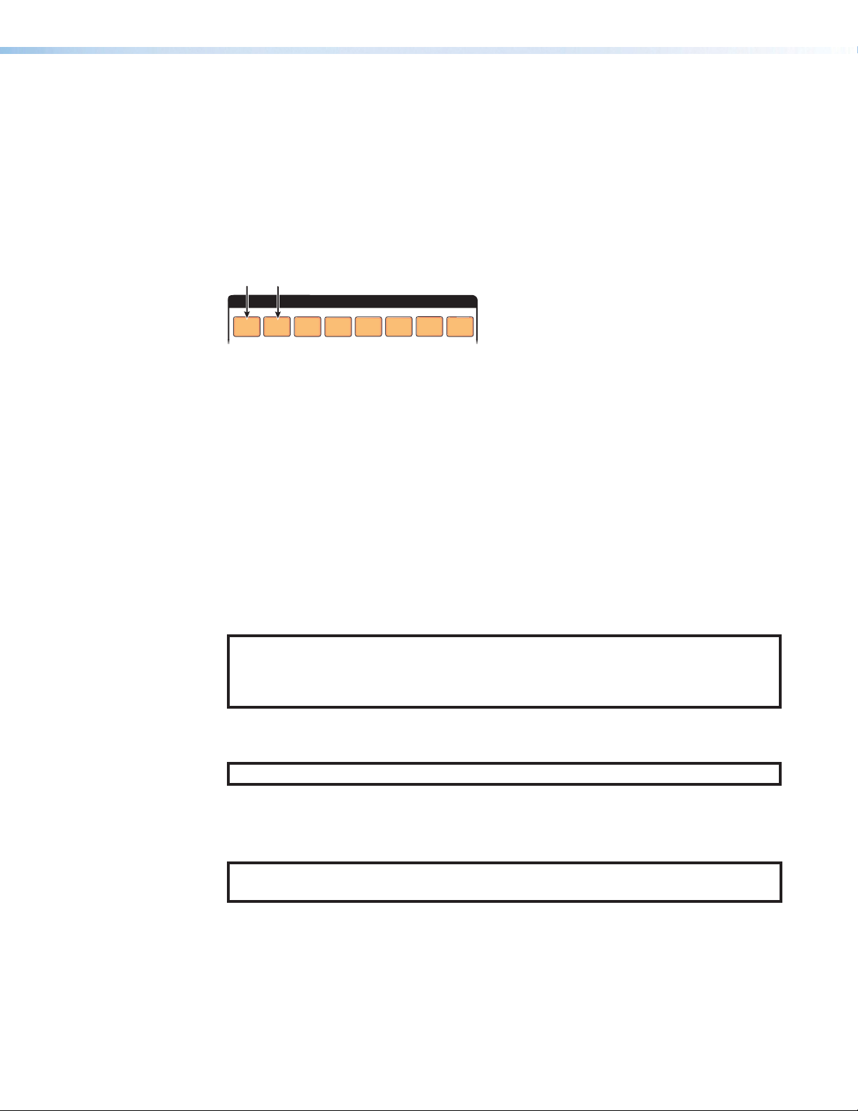
Setting the Button Background Illumination — DXP 168 and 1616 PLUS
Press and hold Input 1 and Input 2 buttons
Only
The buttons on the front panel can be set to have amber background illumination at all times
or the background illumination can be turned off.
To toggle the background illumination on and off, press and hold the Input 1 and Input 2
buttons simultaneously until the button background illumination changes (approximately
2 seconds.
simultaneousely to toggle background illumination
mode on or off.
INPUTS
Resetting
1
Figure 80. Toggle Background Illumination On or Off
There are several methods by which you can reset the DXP PLUS, and some of these
methods allow for four levels of resetting. The following reset methods are available on the
DXP PLUS:
• Front panel buttons (see Resetting the System from the Front Panel) This method
is not available on the DXP 42 PLUS model.
• Front panel (DXP 42 PLUS) or rear panel (all other models) recessed Reset
button (see Resetting Using the Front or Rear Panel Reset Button on page57)
• SIS commands (see the Reset Commands on page84)
• PCS (see the DXP HD 4K PLUS Series Help File)
NOTE: Entering the E ZQQQ } SIS command or performing a mode 5 reset via the
rear panel Reset button (see the Reset Modes Summary on page58) removes
the current passwords (whether user-set or the factory-set serial number), leaving the
unit with no password.
4
3
2
6
5
8
7
Resetting the System from the Front Panel
NOTE: Front panel button reset is not available on the DXP 42 PLUS.
A system reset (also known as a “hard reset”) does the following:
• Clears all ties and presets.
• Clears all video and audio setup and mutes.
NOTE: The system reset does not reset the Internet protocol (IP) settings or replace
user-installed firmware.
The front panel button reset is identical to the E ZXXX} SIS command (see the Reset
Commands).
DXP HD 4K PLUS Series • Operation 55
Page 64

Front panel reset — DXP 168 and 1616 PLUS
Release the Video and Audio buttons.
Continue to hold the
all input and output buttons
to backgr
Audio
Press and hold Video and Audio buttons
Power
VIDEO
AUDIO
Disconnect and reconnect power to the
Release the I/O button.
To reset the DXP 168 or 1616 switcher to the factory default settings:
1. Press and hold the View and Esc buttons while you apply power to the switcher.
while you apply power to the switcher.
I/O
AUDIO
VIDEO
The buttons blink, then
become unlit.
Video and Audio buttons until
ound illumination and the Video and
buttons light.
return to either unlit or
100-240V ~ --A MAX
50-60 Hz
Figure 81. System Reset, DXP 168 and 1616 PLUS
2. Continue to hold the View and Esc buttons until the power-up sequence is completed
and all buttons blink and turn off.
Front panel reset — DXP 44, 84, and 88 PLUS
To reset the switcher to the factory default settings on the DXP 44, 84, and 88 PLUS:
1. Disconnect power from the DXP PLUS, then immediately reconnect it. All front panel
LEDs blink four times, then turn off, leaving the I/O LEDs lit red.
2. Immediately press and hold the I/O button while the front panel LEDs do the following:
a. The Input Signal and HDCP LEDs blink in order in a clockwise, circling pattern.
b. All front panel LEDs blink three times, then turn off.
c. The I/O Video LED lights green.
Power
VIDEO
I/O
All front panel LEDs blink four times, then
turn off. The Video and Audio LEDs light red.
AUDIO
Press and hold the I/O button and continue to
hold it until only the I/O Video LED is lit green.
Figure 82. System Reset via Front Panel Buttons
3. When only the Video LED is lit steadily green, release the I/O button.
I/O
DXP HD 4K PLUS Series • Operation 56
Page 65

Resetting Using the Front or Rear Panel Reset Button
The recessed Reset button is on the front panel of the DXP 42 PLUS (see figure14, D, on
page 21), and on the rear panel of the DXP 44, 84, 88, 168, and 1616 PLUS (see figure4
or figure5, D, on page 11). It initiates various levels of soft resets, which restore various
tiers of switcher settings to their defaults. For different reset levels, press and hold the
button while the switcher is running or press and hold the button while you apply power to
the switcher.
table on the next page provides a summary of the reset modes.
Use a pointed stylus, ballpoint pen, or small screwdriver to press the button.
The
ATTENTION:
• Review the reset modes in the table on the next page carefully. Using the wrong
reset mode could result in unintended loss of flash memory programming, port
reassignment, or a switcher reboot.
• Analysez minutieusement les différents modes de réinitialisation voir tableau page
suivante. Appliquer le mauvais mode de réinitialisation peut causer une perte
inattendue de la programmation de la mémoire flash, une reconfiguration des ports
ou une réinitialisation du sélecteur.
NOTES:
• The reset modes listed in the table close all open IP and Telnet connections and all
sockets.
• The modes described in the table are separate functions, not a continuation from
mode 1 to mode 5.
• There is no reset mode 2 for DXP HD 4K PLUS Series. If you attempt to initiate it,
the Power and Reset LED blinks 3 times but no reset is performed.
DXP HD 4K PLUS Series • Operation 57
Page 66

Reset Modes Summary
Mode Activation Result Purpose/Notes
1
Hold in the recessed Reset button
while applying power to the switcher.
• Restores the factory-installed
firmware for a single power cycle.
• Maintains all user files and settings
(drivers, audio adjustments, IP
settings, and so on) are maintained.
• It does not clear the current
Use mode 1 to
revert to the
factory firmware if
incompatibility issues
arise with userloaded firmware.
configuration.
4
Hold in the Reset button until
the Power and Reset LED blinks
twice (once after approximately 3
seconds and again after 6 seconds).
Then, within 1 second press Reset
momentarily (for less than 1 second).
• Sets the IP address, subnet
address, and gateway address to
the factory defaults.
• Sets port mapping to the factory
default.
• Turns DHCP off.
Mode 4 resets all IP
settings to factory
defaults.
It does not replace
any user-installed
firmware.
• Turn event scripts off.
The Reset LED blinks four times in
quick succession during the reset.
5
Hold in the Reset button until the
Power and Reset LED blinks three
times (once after approximately 3
seconds, again after 6 seconds, and
then again after 9 seconds); then within
1 second press Reset momentarily (for
less than 1 second).
Performs a complete reset to factory
defaults (with the exception of the
firmware), which includes:
• Everything mode 4 does
• Reset of all real time adjustments:
• Clears all ties, presets, and audio
or RS-232 mutes.
• Resets all IP options.
• Removes or clears all switcher
files.
The reset LED blinks four times in
quick succession during the reset.
Mode 5 is useful
if you want to
start over with
configuration and
uploading and also
to replace events.
This reset, equivalent
to the EZQQQ}
SIS command,
also removes the
initial serial number
passwords and
sets them to no
password.
NOTES:
• For modes 4 and 5: Nothing happens if the momentary press does not occur
within 1 second of pressing the Reset button.
• The factory configured passwords for all accounts on this device have been set to
the device serial number. In the event of a complete system reset, the passwords
convert to the default, which is no password.
DXP HD 4K PLUS Series • Operation 58
Page 67

To perform a hardware reset of the switcher (mode 1):
Absolute Reset
(Mode 5)
DXP 1616 Series
Press and hold
1. Use a stylus or small Philips screwdriver to press and hold the Reset button until:
• DXP 44, 84, 88, 168, and 1616 PLUS (see figure83): The front panel Video
and Audio buttons or LEDs blink twice (for a system reset) or three times (for an
absolute reset).
the Reset button.
Reset LED blinks twice.
Release, then immediately
press and release again.
IP
Settings
Reset
(Mode 4)
Press and hold
the Reset button.
6 seconds
RESET
Front panel I/O buttons or LEDs blink twice.
VIDEO
I/O
AUDIO
DXP 88 Series
Reset LED blinks
three times.
9 seconds
RESET
Front panel I/O buttons blink three times.
VIDEO
I/O
AUDIO
DXP 88 Series
RESET
I/O
AUDIO
VIDEO
DXP 1616 Series
Release, then immediately
press and release again.
RESET
I/O
AUDIO
VIDEO
RESET
RESET
Figure 83. Soft Resets (Modes 4 and 5) on DXP 44, 84, 88, 168, and
1616 PLUS
• DXP 42 PLUS: The Reset/Power LED on the front panel (see figure14, J on
page 19) blinks twice (for a system reset) or three times (for an Absolute system
reset).
2. Release the Reset button and then immediately press and release it again. Nothing
happens if the second momentary press does not occur within 1 second.
Troubleshooting
The following are recommendations (listed in the order they should be attempted) for actions
to take if you have problems operating the switcher:
1. Ensure that all devices are plugged in and powered on. The switcher is receiving power
if the Reset/Power LED is lit.
2. Check to see if one or more outputs are muted.
3. Ensure that an active input is selected for output on the switcher.
4. Ensure that the proper signal format is supplied.
5. Check the cabling and make corrections as necessary.
6. Call the Extron S3 Sales & Technical Support Hotline if necessary.
DXP HD 4K PLUS Series • Operation 59
Page 68

Configuration Worksheets
78
Input Sources
Fill in the preset number and use colors, dashes, and so forth, to make connecting lines.
Instead of trying to remember the configuration for each preset, use worksheets to record
this information. Make copies of the appropriate Worksheet Form on page64 and 65,
and use one sheet for each preset configuration. Cross out all unused or inactive inputs and
outputs. The worksheet is generic for all models of DXP PLUS. Disregard or cross out boxes
for inputs and outputs that your switcher does not have.
The following pages contain examples of worksheets for 8-input and 16-input models.
Worksheet Example 1: System Equipment — 8 Inputs and Outputs
Figure 84 shows a worksheet for a DXP PLUS in a fictional organization with the system
hardware annotated. Output 7 has no connection in this organization, so it has been
crossed out on the worksheet.
4K
Camera
Main
podium
Main hall1Main hall2Podium
4K
Camera
1
1 2345678
1
2
123456
monitor
4K
Blu-ray
Player
1
1
PC
Conf.
Room
1
Media
Player
1
Podium
monitor
2
1
1
Demo
Room
1
Station
1
Editing
Station
2
Lobby
monitor
1
Editing
Laptop
Output Destinations
Preset # Title: Video ties:
Weekly status mtg 3
Figure 84. Worksheet Example 1: System Equipment
Inputs include media players, a PC, a laptop, editing stations, and 4K cameras. Output
devices include various 4K monitors.
DXP HD 4K PLUS Series • Operation 60
Page 69

Worksheet Example 2: Daily Configuration — 8 Inputs and Outputs
78
Fill in the preset number and use colors, dashes, and so forth, to make connecting lines.
Input Sources
78
Fill in the preset number and use colors, dashes, and so forth, to make connecting lines.
Input Sources
Figure 85 continues from worksheet example 1 by showing the video ties that make up the
configuration of preset 1. A solid ink line shows video ties.
Editing
4K
4K
4K
Camera
Camera
1
Main
podium
1 2 345678
1
Blu-ray
2
Player
PC
1
1
123456
Main hall1Main hall2Podium
monitor
1
Conf.
Room
1
Output Destinations
Preset # Title: Video ties:
Weekly status mtg 3
Figure 85. Worksheet Example 2: Daily Configuration
In this example:
• The image of the presenter, from the main podium camera (input 1), is:
• Displayed in the main hall (output 1)
• Displayed in the conference room (output 4) to the overflow crowd
• Displayed in the Demo Room (output 6)
• Displayed in the lobby (output 8)
• The presenter has a presentation stored on PC 1 (input 4) that is:
• Displayed in the main hall (output 2)
• Displayed locally on podium 1 (output 3).
Media
Player
1
Podium
monitor
2
Laptop
1
Demo
Room
1
Station
1
Editing
Station
2
Lobby
monitor
Worksheet Example 3: Test Configuration — 8 Inputs and Outputs
The AV system in our fictional organization needs to be fine tuned on a regular basis.
Figure 86 shows a typical test configuration, with an Extron video test generator (input 6)
generating a test pattern to all monitors (outputs 1, 2, 3, 4, 8).
Editing
Media
Player
1
Podium
monitor
2
Laptop
1
Demo
Room
1
Station
1
Editing
Station
2
Lobby
monitor
1
DXP HD 4K PLUS Series • Operation 61
4K
4K
4K
Camera
Camera
1
Main
podium
1
1 2 345678
Blu-ray
2
Player
PC
1
1
123456
Main hall
Main hall
Podium
monitor
1
monitor
2
monitor
1
Conf.
Room
1
Output Destinations
Weekly status mtg
Preset # Title: Video ties:
3
Figure 86. Worksheet Example 3: Test Configuration
Page 70

Worksheet Example 1: System Equipment — 16 Inputs and Outputs
Input Sources
51
Figure 87 shows a worksheet for a DXP PLUS in a fictional organization with the system
hardware annotated. Output 7 has no connection in this organization, so it has been
crossed out on the worksheet.
4K
4K
4K
Camera
Camera
1
Main
podium
1 2 345678
1
Camera
2
PC
1
3
Media
Player
VTG
400DVI
1
Station
1
Editing
Station
12345678
Main hall1Main hall2Podium
monitor
1
Conf.
Room
Podium
Demo
monitor
1
Room
2
1
Lobby
monitor
4K
Camera
5
Media
Player
4K
Camera
2
4
Main
podium
PC
2
2
910111213141
9
10 11 12 13 14 15 16
Main hall3Main hall4Podium
1
monitor
2
Conf.
Room
2
Media
Player
Podium
monitor
4
Media
Player
4
3
Demo
Room
2
Editing
Output Destinations
Preset # Title: Video ties:
Fill in the preset number and use colors, dashes, and so forth, to make connecting lines.
Weekly status mtg 3
Figure 87. Worksheet Example 1: System Equipment
Inputs include media players, PCs, editing stations, 4K cameras, and an Extron
VTG 400DVI. Output devices include various 4K monitors.
The VTG 400DVI video test generator connected to input 6 enables a video test pattern to
be sent to one, several, or all output devices for problem isolation or adjustment purposes.
Editing
Station
3
Editing
Station
4
Lobby
monitor
2
6
DXP HD 4K PLUS Series • Operation 62
Page 71

Worksheet Example 2: Daily Configuration — 16 Inputs and Outputs
51
51
Figure 88 continues from worksheet example 1 by showing the video ties that make up the
configuration of preset 1. A solid ink line shows video ties.
Input Sources
Editing
4K
4K
4K
Camera
Camera
1
Main
podium
1 2 345678
1
Camera
2
PC
1
3
Media
Player
VTG
Station
400DVI
1
1
Editing
Station
2
4K
4K
4K
Camera
4
Camera
5
Camera
6
Media
Player
2
910111213141
Media
PC
Player
2
Editing
Editing
Station
Station
3
3
4
6
12345678
Main hall1Main hall2Podium
monitor
1
Conf.
Room
Podium
Demo
monitor
1
Room
2
1
Lobby
monitor
9
10 11 12 13 14 15 16
Main hall3Main hall4Podium
monitor
2
Conf.
Room
2
Podium
monitor
3
Demo
Room
Lobby
2
monitor
2
Output Destinations
Figure 88. Worksheet Example 2: Daily Configuration
In this example:
• The image of the presenter, from the main podium camera (input 1), is:
• Displayed in the main hall (output 1)
• Displayed in the conference room (output 4) to the overflow crowd
• Displayed in the Demo Room (output 6)
• Displayed in the lobby (output 8)
• The presenter has a presentation stored on PC 1 (input 4) that is:
• Displayed in the main hall (output 2)
• Displayed locally on podium 1 (output 3)
Worksheet Example 3: Test Configuration
The AV system in our fictional organization needs to be fine tuned on a regular basis.
Figure 89 shows a typical test configuration, with an Extron video test generator (input 6)
generating a test pattern to all monitors (outputs 1, 2, 3, 4, 8, and 16).
Input Sources
4K
4K
4K
Camera
Camera
1
Main
podium
1
1 2 345678
Camera
2
PC
1
3
Media
Player
VTG
Station
400DVI
1
1
Editing
Editing
Station
2
4K
4K
Camera
4
Camera
5
4K
Camera
6
Media
PC
Player
2
2
910111213141
Media
Player
3
Editing
Station
3
Editing
Station
4
6
12345678
Main hall
Main hall
Podium
Conf.
Podium
monitor
1
monitor
2
monitor
1
Room
Demo
monitor
1
Room
2
1
Lobby
monitor
9
Main hall3Main hall4Podium
1
Output Destinations
Preset # Title: Video ties:
Fill in the preset number and use colors, dashes, and so forth, to make connecting lines.
3
Weekly status mtg
Figure 89. Worksheet Example 3: Test Configuration
10 11 12 13 14 15 16
Conf.
Podium
monitor
2
Room
monitor
2
Demo
Room
3
2
Lobby
monitor
2
DXP HD 4K PLUS Series • Operation 63
Page 72

Worksheet Form — 8 Inputs and Outputs
Input Sources
Pr
Fill in the preset number and use colors, or dashes, and so on, to make connecting lines.
Disr
1 2 345678
1 2 345678
Output Destinations
eset # Title:
egard or cross out the input and output boxes that do not apply to your switcher.
DXP HD 4K PLUS Configuration Worksheet
DXP HD 4K PLUS Series • Operation 64
Page 73

Worksheet Form — 16 Inputs and Outputs
51
Input Sources
51
6
6
Output Destinations
DXP HD 4K Configuration Worksheet
1 2 345678 910111213141
1 2 345678 910111213141
Preset # Title:
Fill in the preset number and use colors, or dashes, and so on, to make connecting lines. Disregard or cross out the input and output boxes that do not apply to
your switcher.
DXP HD 4K PLUS Series • Operation 65
Page 74

SIS Configuration and Control
The DXP HD 4K PLUS Series can be configured and controlled with Extron Simple
Instruction Set commands. This section describes the communication between a connected
host and the DXP PLUS. Topics are:
• Connection Methods
• Host and Matrix Switcher Communication
• SIS Overview
• Command and Response Table - DXP 44, 84, 88, 168, and 1616 PLUS
• Command and Response Table - DXP 42
Connection Methods
Attach the host device to one of the following connectors:
• Remote RS-232 connector (see figure4 (DXP 168 and 1616), figure5 (DXP 44, 84,
and 88), or figure6 (DXP 42), E on page 11)
• LAN connector (F)
• USB connector (see figure12 (DXP 168 and 1616), figure13 (DXP 44, 84, and 88), or
figure14 (DXP 42), A, on page 21)
Commands can be entered using a Telnet application such as the Extron DataViewer,
available at www.extron.com (see the DataViewer Help file for more details).
Host and Matrix Switcher Communication
SIS commands consist of one or more characters per field. No special characters are
required to begin or end a command sequence. Commands can be entered
back-to-back in a string with no spaces. When the switcher determines that a command
is valid, it executes the command and sends a response to the host device. All responses
from the switcher to the host end with a carriage return and a line feed (CR/LF = ]),
indicating the end of the response character string (one or more characters).
Copyright Information
The copyright message is displayed upon connecting to a switcher via TCP/IP or Telnet or,
after a power cycle, via RS-232, depending on the matrix switcher model.
(c) Copyright 20nn, Extron Electronics, DXP nn HD 4K Plus, Vn.nn, 60-nnnn-nn]
Ddd, DD Mmm YYYY HH:MM:SS]
20nn is the year.
DXP nn HD 4K Plus is the model name.
Vn.nn is the firmware version number.
60-nnnn-nn is the model part number.
Ddd, DD Mmm YYYY HH:MM:SS are Day, date, and time as in Mon, 17 Feb 2020 11:27:33)
DXP HD 4K PLUS Series • SIS Configuration and Control 66
Page 75

Device-Initiated Messages
When a local event such as a front panel selection or adjustment takes place, the matrix
switcher responds by sending a message to the host. No response is required from the
host. Example switcher-initiated messages are listed here.
• ]
Password:
The ]Password: prompt requires a password (administrator level or user level)
followed by a carriage return. If the correct password is entered, the unit responds with
]Login Administrator ] or ] Login User], depending on the password
entered. If passwords are the same for both administrator and user, the switcher
defaults to administrator privileges.
The password prompt is redisplayed if an incorrect password is entered.
NOTES:
• The factory configured passwords for all accounts on these devices have been
set to the device serial number. Passwords are case sensitive.
• Performing a unit factory reset (entering an E ZQQQ } SIS command or
a mode 5 reset via the rear panel Reset button) removes the serial number
passwords, leaving the unit with no password.
• Qik]
The switcher initiates the Qik message when a front panel switching operation occurs.
• RprX1&]
The switcher initiates the Rpr message when a memory preset is recalled from the front
panel. X1& is the preset number.
• SprX1&]
The switcher initiates the Spr message when a memory preset is saved from the front
panel. X1& is the preset number.
• VmtX@*X1@]
The switcher initiates the Vmt message when a video output mute is toggled on or off
from the front panel. X@ is the output number. X1@ is the video mute status (0 = off,
1 = on).
• AmtX@*X1#]
The switcher initiates the Amt message when an audio output mute is toggled on or off
from the front panel. X@ is the output number. X1# is the mute status (0 = off, 1 = on).
• ExeX2)]
The switcher initiates the Exe message when the Front Panel Lockout mode is toggled
on or off from the front panel. X2) is the lock mode (0 = off, 1 = view only, 2 = basic
mode only)
• HplgOX@ ]
The switcher initiates the HplgO message when a hot plug event is detected on an
output (for example, if the display is disconnected from the unit). X@ is the output
number.
• Reconfig]
The switcher sends this response upon any change of input frequency on the currently
selected input or inputs.
DXP HD 4K PLUS Series • SIS Configuration and Control 67
Page 76

Error Responses
When the switcher receives a valid command, it executes the command and sends a
response to the host device. If the unit is unable to execute the command, it returns an error
response to the host.
Error codes
E01 — Invalid input number
E10 — Invalid command
E11 — Invalid preset number
E12 — Invalid output number
E13 — Invalid parameter
E14 — Not valid for this configuration
E17 — Invalid command for signal type
E18 — System or command timed out
E21 — Invalid room number
E22 — Busy
E24 — Privilege violation
E25 — Device not present
E26 — Maximum number of connections
exceeded
E27 — Invalid event number
E28 — Bad filename or file not found
Error response references
These references in the command and response tables note particular error responses to
that command. For example:
24
= Commands that give an E24 (privilege violation) error if not administrator level
Connection Timeouts
An Ethernet link disconnects after a designated period of no communications. By default,
this timeout duration is 5 minutes (see Port timeout on page87 to change this value).
NOTE: Extron recommends periodically issuing query commands (see Information
Requests starting on page85) to keep the connection active. If there are long
idle periods, Extron recommends disconnecting and reopening the connection when
another command must be sent.
Number of Connections
A DXP HD 4K PLUS Series switcher can have up to 200 simultaneous TCP connections,
including all http and Telnet connections. When the connection limit is reached, the switcher
accepts no new connections until some have been closed. No error message or indication
is given that the connection limit has been reached. To maximize performance, keep the
number of connections low and close unnecessary ones.
DXP HD 4K PLUS Series • SIS Configuration and Control 68
Page 77

SIS Overview
Space
Using the Command and Response Tables
The Command and Response Tables, starting on page 75, list the commands that the
switchers recognize as valid, the responses that are returned to the host, a description
of the command function or the results of executing the command, and examples of
commands in ASCII.
NOTE: Upper- and lowercase text can be used interchangeably unless otherwise
stated.
ASCII to Hex Conversion Table
•
Figure 90. ASCII to Hexadecimal Character Conversion Table
Verbose Mode
The connection to a DXP PLUS switcher can be used to monitor for changes that occur on
the switcher, such as front panel operations and SIS commands from a TCP/IP connection
or the RS-232 serial port. To receive change notices from the switcher, you must enable
verbose mode 1 or 3 (see the Verbose Mode commands starting on page85). In
verbose mode 1 or 3, changes are reported in messages that resemble SIS command
responses.
DXP HD 4K PLUS Series • SIS Configuration and Control 69
Page 78

Symbol Definitions
• = Space
= Carriage return with line feed
]
= Carriage return with no line feed
}
or |
= Escape key
E
or W
24
= Superscripts indicate the error message displayed if the command is entered
X!
= Input number
X@
= Output number
X#
= Enable or disable
X$
= Name 16 alphanumeric characters (12 characters for
incorrectly or with invalid parameters (see Error Responses on page68).
1 through <maximum number of inputs>
0 = untie (for ties If applicable)
1 through <maximum number of outputs>:
DXP 42 PLUS: 1 or 2
DXP 44 and 84 PLUS: 1-4
DXP 88 and 168 PLUS: 1-8
DXP 1616 PLUS: 1-16
0 = untie (for ties if applicable)
0 = disable
1 = enable
room names)
NOTE: The pipe (|) character cannot be used in names. All other characters, including
symbols and spaces, are permitted.
X%
= Analog audio and S/PDIF
output number
X^
= HDCP Authorized device
X&
= Input HDCP status
X*
= Output format —
DXP 42
Output format —
DXP 44, 84, 88, 168,
and 1616 PLUS
X(
= Color bit depth
X1)
= HDCP mode
1 or 2
0 = block HDCP encryption
1 = allow HDCP encryption (default)
0 = no source detected
1 = source is HDCP compliant
2 = source is not HDCP compliant
0 = auto (default)
1 = DVI RGB 4:4:4 Full
2 = HDMI RGB 4:4:4 Full
3 = HDMI RGB 4:4:4 Limited
4 = HDMI YUV 4:4:4 Limited
5 = HDMI YUV 4:2:2 Limited
6 = HDMI YUV 4:2:0 Limited
0 = pass-through (default)
1 = RGB (color quantization follows input)
2 = YUV 444 (color quantization follows input)
3 = YUV 422 (color quantization follows input)
0 = auto (default)
1 = force 8-bit
0 = auto (follow the input, default)
1 = on (always encrypt HDMI outputs)
2 = none (do not send HDCP content to the sink)
(DXP 42 only)
DXP HD 4K PLUS Series • SIS Configuration and Control 70
Page 79

X1!
= Output HDCP status
X1@
= Video mute
X1#
= Audio mute
X1$
= Output mute
X1%
= Input attenuation
X1^
= Output volume
0 = no sink is detected
1 = sink is connected, but does not support
HDCP
2 = sink is connected, supports HDCP, but is
currently not encrypted
3 = sink is connected, supports all HDCP
versions, and is currently encrypted
0 = unmute
1 = video mute
2 = video and sync mute
0 = unmute
1 = HDMI audio mute
2 = Analog audio mute
3 = HDMI and analog audio mute
4 = S/PDIF mute
5 = HDMI audio and S/PDIF mute
6 = Analog audio and S/PDIF mute
7 = HDMI and analog audio, and S/PDIF mute
0 = unmute
1 = video mute (one or more outputs)
2 = audio mute (one or more outputs)
3 = video and audio mute (one or more outputs)
-20 to 00 in dB (00 = default)
0 to 100 percent in approximately 1.28 dB intervals
(100 = default)
NOTE: If X1^ exceeds the acceptable volume range specified in the Output
Volume commands on page80, an E13 error message is returned.
X1&
= Global preset number
X1*
= Room number
X1(
= Room preset number
X2)
= Front Panel Lockout
mode
X2!
= HDCP notification —
screen background color
X2@
= Signal status
DXP 88 PLUS Series: 1-16
DXP 1616 PLUS Series: 1-32
1-10
1-10
0 = unlock the front panel
1 = mode 1 (complete front panel lockout)
2 = mode 2 (tie configuration and preset
management only, default)
0 = black screen
1 = green screen (default)
0 = no signal detected
1 = input signal detected
DXP HD 4K PLUS Series • SIS Configuration and Control 71
Page 80

X2#
= Verbose mode
NOTES:
• In verbose response mode, the DXP PLUS returns unsolicited
responses for value and setting changes that may result from a signal
change, or a setting adjustment made via another interface.
Example: The DXP PLUS can send out a notice of a change in some
setting without receiving a query via a PC or a control system. That
change could have been a result of an internal process or a selection
made via the PCS program. This is a verbose (wordy) relationship
between the controller and a connected device.
• If tagged responses are enabled, all “view” commands return the
command string plus the data, the same as in responses for setting a
value.
For example:
Command: X!*\
Response: VtypX!*
X#]
(untagged)
X2$
= Power save mode
X2%
= Firmware version
X2^
= Verbose firmware version
X2&
= Power supply In voltage
X2*
= Temperature In degrees Celsius
X2(
= Fan In RPM
X3)
= IP address
X3!
= Subnet mask
X3@
= Gateway address
X3#
= MAC address
X3$
= Open connections
0 = None (default for LAN connection)
1 = Verbose mode (default for RS-232 and USB
connection)
2 = Tagged responses to queries
3 = Verbose mode and tagged responses
X#]
(tagged) or
0 = Normal operation (default)
1 = Limited functionality — disable all functions
except IP, USB, and RS-232, and reduce fan
speed.
To return to mode 0: Press a front panel
button, issue an SIS command, cycle
power, or open PCS.
2 = Limited functionality — disable all functions
except IP, USB, and RS-232 ports, and
reduce fan speed. Front panel is
non-responsive. Responds only to SIS viewing
commands and E 0PSAV}.
To return to mode 0: Enter the
E 0PSAV} command or open PCS.
n.nn
[version]-[description]-[upload date and
time]
nnn.nnn.nnn.nnn
(192.168.254.254 = default)
nnn.nnn.nnn.nnn (255.255.0.0 = default)
nnn.nnn.nnn.nnn (0.0.0.0 = default)
00-05-A6-xx-xx-xx
0-<maximum number of open connections>
DXP HD 4K PLUS Series • SIS Configuration and Control 72
Page 81

X3%
= Port timeout
X3^
= Device name Maximum 63 alphanumeric characters or hyphens.
X3&
= Date and time
X3*
= Date and time (view only)
X3(
= GMT offset
X4)
= Time zone Time zone code (see the View available time
X4!
= Time zone description
X4@
= Password 128 characters maximum
1 to 65000 in 10-second intervals (30 = default)
The first character must be an alpha character.
The last character cannot be a hyphen. No blank
or space characters are permitted. Uppercase and
lowercase letters are interchangeable.
In the format MM/DD/YY•HH:mm:SS
MM = month: 01 (January) to 12 (December)
DD = day: 01 to 31 (depending on the month)
YY = year: 00 to 99 (last two digits)
HH = hour: 00 to 23
mm = minute: 00 to 59
SS = second: 00 to 59
In the format DAY,•DD•MMM•YYYY•HH:mm:SS
DAY =day of the week: Mon to Sun
DD = date: 01 to 31 (depending on the month)
MMM = month: 01 to 12
YYYY = year: 2000 to 2099
HH = hour: 00 to 23
mm = minute: 00 to 59
SS = second: 00 to 59
-12:00 to +14:00
zones command on page88 to view a list of
available time zones). The code is followed by an *
in the response.
In the format (UTCX3()•<Description>
This is the UTC equivalent for a particular time zone
as well as a general description of the geographical
area.
NOTES:
• The pipe (|) character is invalid for passwords.
• The factory configured passwords for all accounts on this device have
been set to the device serial number. In the event of a complete system
reset, the passwords revert to the default, which is no password.
= Filename
X4#
X4%
= Serial port number
X4^
= Baud rate
X4&
= Parity
X4*
= Data bits
X4(
= Stop bits
X5)
= EDID record 256 bytes of binary data in Hex
X5!
= EDID resolution and rate Native resolution and refresh rate from current EDID
DXP HD 4K PLUS Series • SIS Configuration and Control 73
Can carry a full path name. EDID file format is .bin,
carrying 128 or 256 bytes of binary data.
01 – 99
9600 (default), 19200, 38400, 115200
Odd, Even, None (default), Mark, Space
Enter only the first letter.
7, 8 (default)
1 (default), 2
input assignment, translated from Hex
Page 82

X5@
= EDID slot
(See EDID tables for
DXP HD 4K PLUS
starting on page5.)
= EDID filename Name and path of the EDID file (can be a full path
X5#
= MKP mode Volume steps:
X5$
Default — 1080p @ 60 Hz
DXP 42 PLUS — 01-04 = input slot, manually
populated via PCS
DXP 44 PLUS — 01-04 = input slot,
05-08 = automatically populated with sink
EDID from the output.
DXP 84 PLUS — 01-08 = input slot,
09-12 = automatically populated with sink
EDID from the output.
DXP 88 PLUS — 01-08 = input slot,
09-16 = automatically populated with sink
EDID from the output.
DXP 168 PLUS — 01-16 = input slot,
17-24 = automatically populated with sink
EDID from the output.
DXP 1616 PLUS — 01-16 = input slot,
17-32 = automatically populated with sink
EDID from the output.
name). The EDID file format is .bin, carrying 128 or
256 bytes of binary data.
Default = EXN_HDMI_1080p60_2Ch.bin
1 = Set DXP PLUS to normal operation, 1-100
steps (default).
2 = Set DXP PLUS to MKP volume control range,
1-64 steps.
NOTES:
= Subnet mask for CISG
X5%
= Device part number
X5^
= Audio tie mode for front
X5&
• Entering the E ZQQQ} or E ZXXX} system reset command
resets the MKP mode to the factory default (mode 1).
• Affects all analog and S/PDIF audio outputs.
A 2-digit code with optional leading zero.
command
DXP 42 — 60-1678-01
DXP 44 — 60-1493-01
DXP 84 — 60-1494-01
DXP 88 — 60-1495-01
DXP 168 — 60-1496-01
DXP 1616 — 60-1497-01
0 = Front panel buttons switch video only (default).
panel buttons
1 = Front panel buttons switch video and analog
audio.
NOTE:
• When an input is switched to output 1,
analog audio output 3 is also selected.
• When an input is switched to output 2,
analog audio output 4 is also selected.
DXP HD 4K PLUS Series • SIS Configuration and Control 74
Page 83

Command and Response Table — DXP 44, 84, 88, 168, and 1616 PLUS
Command ASCII Command
(Host to Switcher)
Response
(Switcher to Host)
Additional Description
Input and Output Tie Commands
Individual Ties
Tie HDMI input to HDMI and
audio outputs
NOTE: All HDMI source signals switch with embedded audio.
Example: Breaking a tie
Tie HDMI input to HDMI output
X!*X@! OutX@•In X!•All]
0*2! Out2 In0 All
X!*X@ % or
OutX@•In X!•Vid]
X!*X@&
Tie HDMI audio input to audio
only output (audio output 2 only)
Ties from an Input to All Outputs
Tie HDMI input to all HDMI and
audio outputs
Tie HDMI input to all HDMI
outputs
Tie HDMI audio input to all audio
only outputs (audio output 2 only)
Quick Tie
Multiple ties
Example (DXP 88 PLUS HD
4K PLUS)
X!*X@ $ OutX@•In X!•Aud]
X!*! InX!•All]
X!*% or
InX!•Vid]
X!*&
X!*$ InX!•Aud]
E+Q X!*X@%...X!*X@!} Qik]
(& can be substituted for %.)
E+Q3*4%6*1$3*2!} Qik]
(& can be substituted for %.)
Tie or untie an HDMI video
input with embedded audio
to an HDMI output (analog
or S/PDIF) with the extracted
audio.
Untie an HDMI video input
with embedded audio from the
HDMI output.
Tie or untie an HDMI input to
an HDMI output.
Tie or untie an HDMI audio
input to an analog audio and
S/PDIF output (audio output 2
only).
Tie an HDMI input to all HDMI
and audio outputs.
Tie an HDMI input to all HDMI
outputs.
Tie an HDMI audio input to
all analog audio and S/PDIF
outputs (audio output 2 only).
Make multiple ties in one
command entry (applies to
HDMI and audio outputs).
Tie HDMI input 3 to HDMI
output 4, HDMI audio input 6
to analog audio output 1, and
HDMI input 3 to HDMI and
analog audio output 2.
KEY:
X! = Input number
X@ = Output number
0 = untie (for ties If applicable)
1 through <maximum number of inputs>
0 = untie (for ties if applicable)
HDMI output, 1 through <maximum number of outputs>:
DXP 44 and 84 PLUS — 1-4, DXP 88 PLUS and 168 PLUS — 1-8,
DXP 1616 PLUS — 1-16
DXP HD 4K PLUS Series • SIS Configuration and Control 75
Page 84

Command ASCII Command
(Host to Switcher)
Input and Output Tie Commands (continued)
View Ties
Response
(Switcher to Host)
Additional Description
View HDMI and audio output
tie
View HDMI output tie
View audio output tie
Input Configuration Commands
Input Name
Set input name
View input name
HDCP Authorized Device
Set HDCP Authorized device
setting
View HDCP Authorized device
setting
Input HDCP Status
View input HDCP status
View all input HDCP status
X@! X!]
OutX@•InX!•All]
X@% or
X!]
X@&
OutX@•InX!•Vid]
X@$ X!]
OutX@•InX!•Aud]
EX!,X$ NI} NmiX!,X$]
EX! NI} X$]
NmiX!,X$ ]
EE X!*X^HDCP} HdcpEX!*X^ ]
EE X! HDCP} X^]
HdcpEX!*X^ ]
EI X! HDCP} X&]
HdcpIX!*X&]
EIHDCP} X&1X&
2
...X&
n
HdcpI00*X&
1X&2
]
...X&
View input tied to an HDMI
and audio output.
Verbose modes 2 and 3
View input tied to an HDMI
output.
Verbose modes 2 and 3
View input tied to an audio
output.
Verbose modes 2 and 3
Set the name of an input.
View name of an input.
Verbose modes 2 and 3
Set the HDCP Authorized
device setting for an input.
View the HDCP Authorized
device setting for an input.
Verbose modes 2 and 3
View the HDCP status on
an input.
Verbose modes 2 and 3
View the HDCP status for
all inputs. n = the maximum
number of inputs
n
]
Verbose modes 2 and 3
KEY:
X! = Input number
X@ = Output number
X$ = Name
X^ = HDCP Authorized device
X& = Input HDCP status
1 through <maximum number of inputs>
0 = untie (for ties if applicable)
HDMI output, 1 through <maximum number of outputs>:
DXP 44 and 84 PLUS — 1-4, DXP 88 PLUS and 168 PLUS — 1-8,
DXP 1616 PLUS — 1-16
Up to 16 alphanumeric characters
0 = block HDCP encryption
1 = allow HDCP encryption (default)
0 = no source detected
1 = source is HDCP compliant
2 = source is not HDCP compliant
DXP HD 4K PLUS Series • SIS Configuration and Control 76
Page 85

Command ASCII Command
(Host to Switcher)
Response
(Switcher to Host)
Input and Output Tie Commands (continued)
EDID Commands
NOTE: See EDID Minder on page4 for information on available EDID.
Additional Description
View EDID in Hex
View EDID native resolution
Import EDID
Export EDID
KEY:
X! = Input number
X5) = EDID record
X5! = EDID resolution and rate
X5@ = EDID slot
ERX!EDID} X5)]
EdidRX5)]
ENX!EDID} X5!]
EdidNX5!]
View the EDID X5) in Hex
from input slot X!.
Verbose modes 2 and 3
View the EDID native
resolution and refresh X5!
from input slot X!.
Verbose modes 2 and 3
EIX5@,X5#EDID} EIX5@] Import EDID table X5@ from
X5#.
EEX5@,X5#EDID} EEX5@] Export EDID table X5@ to
X5#.
1 through <maximum number of outputs>
256 bytes of binary data in Hex
Native resolution and refresh rate from current EDID input assignment,
translated from Hex
DXP 42 PLUS — 01-04 = input slot, manually populated via PCS
DXP 44 PLUS — 01-04 = input slot,
05-08 = automatically populated with sink EDID from the output.
DXP 84 PLUS — 01-08 = input slot, 09-12 = automatically populated with
sink EDID from the output.
DXP 88 PLUS — 01-08 = input slot, 09-16 = automatically populated with
sink EDID from the output.
DXP 168 PLUS — 01-16 = input slot, 17-24 = automatically populated
with sink EDID from the output.
DXP 1616 PLUS — 01-16 = input slot, 17-32 = automatically populated
with sink EDID from the output.
NOTE: See EDID tables for DXP HD 4K PLUS starting on page5
for lists of the available EDID.
X5# = EDID filename
EDID file name and path (can be a full path name). EDID file format is .bin
carrying 128 or 256 bytes of binary data.
DXP HD 4K PLUS Series • SIS Configuration and Control 77
Page 86

Command ASCII Command
(Host to Switcher)
Output Configuration Commands
Output Name
Set output name
View output name
Output Format
Set output format
View output format
Output HDCP Mode
Set output HDCP mode to
Auto
Set output HDCP mode to On
View HDCP mode
Output HDCP Status
View output HDCP status
View all outputs HDCP status
EX@,X$ NO} NmoX@,X$]
EX@ NO} X$]
EX@*X* VTPO} VtpoX@*X*] Set format X* of output X@.
EX@ VTPO} X*]
ESX@*0HDCP} HdcpSX@*0] Set output X@ HDCP to
ESX@*1HDCP} HdcpSX@*1] Set output X@ HDCP to
ESX@HDCP} X1)]
EO X@ HDCP} X1!]
EOHDCP} X1!1X1!
Response
(Switcher to Host)
NmoX@,X$ ]
VtpoX@*X* ]
HdcpSX@*X1)]
HdcpOX@*X1!]
2
HdcpO00*X1!
...X1!
1
X1!
n
]
2
...X1!
Additional Description
Set the name of an output.
View the name of an
output.
Verbose modes 2 and 3
View the format of an
output.
Verbose modes 2 and 3
Auto.
always encrypted.
View the HDCP mode.
Verbose modes 2 and 3
View the HDCP status of
an output.
Verbose mode 2 and 3
View the HDCP status of all
outputs.
n
= maximum number of
outputs
n
]
Verbose modes 2 and 3
KEY:
X@ = Output number
X$ = Name
X* = Output format
X1) = Output HDCP mode
X1! = Output HDCP status
HDMI output, 1 through <maximum number of outputs>:
DXP 44 and 84 PLUS — 1-4, DXP 88 PLUS and 168 — 1-8,
DXP 1616 PLUS — 1-16
16 alphanumeric characters
0 = pass-through (default)
1 = RGB (color quantization follows input)
2 = YUV 444 (color quantization follows input)
3 = YUV 422 (color quantization follows input)
0 = auto (follow the input, default)
1 = on (always encrypt HDMI outputs)
0 = no sink connected
1 = sink connected but does not support HDCP
2 = sink connected and supports HDCP, but currently not encrypted
3 = sink connected, supports HDCP, and is currently encrypted
DXP HD 4K PLUS Series • SIS Configuration and Control 78
Page 87

Command ASCII Command
(Host to Switcher)
Response
(Switcher to Host)
Output Configuration Commands (continued)
Color Bit Depth
Set color bit depth
View color bit depth
setting
HDMI Video Mutes
Set HDMI video mute
NOTE: This command mutes both the HDMI video and the embedded audio.
EX@*X( BITD} Bitd X@*X(]
EX@ BITD} X(]
BitdX@* X(]
X@*X1@ B Vmt X@*X1@ ]
Additional Description
Set the color bit depth of an
output.
View the color bit depth of
an output.
Verbose mode 2 and 3
Set mute of an output.
View HDMI video mute
status
Set HDMI video mute to
all outputs
View all output mutes
Output 5 V Pulse
Pulse 5 V on HDMI
output
KEY:
X@ = Output number
X( = Color bit depth
X1) = HDCP mode
X1@ = Video mute
X1$ = Output mute
X@B X1@]
VmtX@*X1@]
X1@*B VmtX1@]
EVM} X1$1X1$
2
...X1$
MutX1$
1
X1$
EPX@ HPLG} HplgPX@]
HDMI output, 1 through <maximum number of outputs>:
DXP 44 and 84 PLUS — 1-4, DXP 88 PLUS and 168 PLUS — 1-8,
DXP 1616 PLUS — 1-16
0 = auto (default), 1 = force 8-bit
0 = auto (follow the input, default)
1 = on (always encrypt HDMI outputs)
0 = unmute, 1 = video mute, 2 = video and sync mute
0 = no mutes
1 = video mute (one or more outputs)
2 = audio mute (one or more outputs)
3 = video and audio mute (one or more outputs)
n
2
...X1$
]
View mute setting X1@ of
output X@.
Verbose modes 2 and 3
Set mute of all outputs.
View the mute status of
all outputs. n = maximum
number of outputs.
n
]
Verbose modes 2 and 3
Momentarily toggle the
HDMI 5 V off and on to
simulate an output X@ hot
plug event.
DXP HD 4K PLUS Series • SIS Configuration and Control 79
Page 88

Command ASCII Command
(Host to Switcher)
Response
(Switcher to Host)
Audio Configuration Commands
Input Attenuation
Set attenuation
Decrease attenuation
Increase attenuation
View attenuation
Output Volume (Analog Audio and S/PDIF Outputs Only)
Set volume
Increase volume
Decrease volume
View volume level
Audio Mute
X!*-X1% G InX!
X!+G InX!
X!-G InX!
X!G X1%]
X@*X1^ V OutX@
X@+V OutX@
X@-V OutX@
X@V X1^]
OutX@•VolX1^]
•
•
•
AudX1%]
AudX1%]
AudX1%]
VolX1^]
•
VolX1^]
•
VolX1^]
•
Additional Description
Set the attenuation level of input
X! to X1%.
Increase the attenuation level of an
input by 1 dB.
Decrease the attenuation level of
an input by 1 dB.
View the attenuation level of an
input.
Set the volume level of an output.
Increase the volume level of an
output by 1.28 dB.
Decrease volume level of output
X@ by 1.28 dB.
View the volume level of an output.
Verbose modes 2 and 3
NOTES:
DXP 88 PLUS series — For outputs 1–2, X1# = 0–7. For outputs 3-8, X1# = 0–1.
DXP 1616 PLUS series — For outputs 1–4, X1# = 0–7. For outputs 5-16, X1# = 0–1.
Set audio mute
View audio mute status
Set audio mute to all
KEY:
X! = Input number
X@ = Output number
X# = Enable or disable
X1# = Audio mute
X1% = Input attenuation
X1^ = Output volume
X@*X1# Z AmtX@*X1#]
Set the mute status of an output.
X@Z X1#] View mute status of output X@.
X#*Z AmtX#]
1 through <maximum number of inputs>
HDMI output, 1 through <maximum number of outputs>:
DXP 44 and 84 PLUS — 1-4, DXP 88 PLUS and 168 PLUS — 1-8,
DXP 1616 PLUS — 1-16
0 = disable (unmute), 1 = enable (mute)
0 = unmute 5 = HDMI audio and S/PDIF mute
1 = HDMI audio mute 6 = analog audio and S/PDIF mute
2 = analog audio mute 7 = HDMI audio, analog audio, and
3 = HDMI and analog audio mute S/PDIF mute
4 = S/PDIF mute
-20 to 00 in dB (00 = default)
0 to 100 percent in approximately 1.28 dB intervals (100 = default)
0 to 64 percent in MKP mode (see the MKP Mode for Volume Control on
page90).
Mute or unmute all outputs.
NOTE: If X1^ exceeds the acceptable volume range specified in the analog output volume setting
commands, above, an E13 error message is returned.
DXP HD 4K PLUS Series • SIS Configuration and Control 80
Page 89

Command ASCII Command
(Host to Switcher)
Preset Commands
Global Presets
Response
(Switcher to Host)
Additional Description
Save global preset
Recall global preset
Directly write global preset
NOTE: Before using the direct write of a global preset, always clear that global preset (see EX1&ZG},
below). In a directly written preset, the tied input for each output position (or no tied input) remains
unchanged unless overwritten or cleared. If you do not clear the preset number before directly writing
another preset to it, ties that are part of the previous version may become part of the new preset.
View global HDMI preset
View global audio preset
X1&, SprX1&]
X1&. RprX1&]
E+X1& P X!*X@%... X!*X@ %}
SprX1&]
1
1
X!
•
...X!
•
2
•
EX1&*01*1VC} X!
VgpX1&*Out01• X!
EX1&*01*2VC} X!
VgpX1&*Out01• X!
...X!
2 or 4
16
...--
•
Vid]
•
1
16
1
...X!
•
Aud]
•
...X!
•
Save the current
configuration to a global
preset.
Apply a global preset
configuration.
Save a specified
configuration to a global
preset in one entry.
View the inputs tied to
each output for a global
preset.
2 or 4
Verbose modes 2 and 3:
View the inputs tied to
each audio-only output for
a global preset.
-- = output is not
applicable.
2 or 4
Verbose modes 2 and 3:
...--
•
...--
•
16
•
16
•
Vid]
Aud]
Set global preset name
View global preset name
EX1&,X$ NG} NmgX1&,X$]
EX1& NG} X$]
NmgX1&,X$]
Reset all global presets
Reset individual preset
KEY:
X! = Input number
X@ = Output number
X$ = Name
EZG} Zpg]
EX1& ZG} ZpgX1& ]
1 through <maximum number of inputs>
HDMI output, 1 through <maximum number of outputs>:
DXP 44 and 84 PLUS — 1-4, DXP 88 PLUS and 168 PLUS — 1-8,
DXP 1616 PLUS — 1-16
16 alphanumeric characters ([unassigned] for presets not saved)
X1& = Global preset number 1-16. X1& can be 0 for viewing current ties only.
NOTE: n = maximum number of outputs.
DXP HD 4K PLUS Series • SIS Configuration and Control 81
Set a global preset name.
View a global preset
name.
Verbose modes 2 and 3
Clear all global presets.
Clear an individual global
preset.
Page 90

Command ASCII Command
(Host to Switcher)
Preset Commands (continued)
Rooms
Set room outputs
Example
View room outputs
Set room name
View room name
Reset room map
Reset individual room
Room Presets
NOTE: n = maximum number of outputs.
EX1*,X@
n
X@
MR}
E7,3,4,7 MR} Mpr 7,3,4,7]
EX1* MR} X@
EX1*,X$ NR} NmrX1*,X$]
EX1*NR} X$]
EZR} Zpr]
EX1* ZR} ZprX1*]
1
,X@2...
Response
(Switcher to Host)
MprX1*,X@1,...X@
1
n
,...X@
NmrX1*,X$]
]
n
]
Additional Description
Set outputs to a room.
n
= desired number
of outputs within the
maximum number.
Assign outputs 3, 4, and 7
to room 7.
View the outputs of a
room.
Set a room name.
View a room name.
Verbose modes 2 and 3
Clear all room and output
configurations.
Clear a room output
configuration.
Save room preset
Recall room preset
Directly write room preset
View room HDMI preset
KEY:
X! = Input number
X@ = Output number
X$ = Name
X1* = Room number
X1( = Room preset number
X1**X1(, Rmm X1*•Spr X1(]
X1**X1(. Rmm X1*•Rpr X1(]
E+X1**X1( PX!*X@%... X!*X@%}
RmmX1*•Spr X1( ]
EX1**X1(*01*1VC} X!
1 through <maximum number of inputs>.
HDMI output, 1 through <maximum number of outputs>:
DXP 44 and 84 PLUS — 1-4, DXP 88 PLUS and 168 PLUS — 1-8,
DXP 1616 PLUS — 1-16
16 alphanumeric characters ([unassigned] for presets that have not
been saved)
1 through 10
1 through 10
1
•X!2•... X!n•Vid ]
Save the current
configuration to a room
preset.
Apply a room preset
configuration.
Save a specified
configuration in one
command entry (see
Input and Output
Tie Commands
on page75 for
independent tie
commands).
View the inputs tied to
each output of a room
preset.
DXP HD 4K PLUS Series • SIS Configuration and Control 82
Page 91

Command ASCII Command
(Host to Switcher)
Preset Commands (continued)
Room Presets (continued)
View room audio preset
Set room preset name
View room preset name
Reset all room presets
Reset individual room preset
EX1**X1(*01*2VC} X!
EX1**X1(,X$NP} NmpX1**X1(,X$ ]
EX1**X1( NP} X$ ]
EZP} Zpp]
EX1**X1( ZP} Zpp X1**X1(]
Advanced Configuration Commands
Front Panel Lockout Mode (Executive Mode)
Set Front Panel Lockout
mode
View Front Panel Lockout
mode
Video Signal Presence
View video signal presence
status
X2)X Exe X2) ]
X
0LS
Response
(Switcher to Host)
1
2
X!
...--X!
•
•
n
•
NmpX1**X1(,X$ ]
X2)]
X2@1X2@
2
...X2@
n
]
Frq00
X2@1X2@
•
2
...
X2@n]
Additional Description
Aud]
View the inputs tied to
each audio output of a
room preset.
-- = output is not
applicable.
Define a room preset
name.
View a room preset name.
Verbose modes 2 and 3
Clear all room preset
configurations.
Clear a room preset.
Set the accessibility to
front panel operation.
View the accessibility level
for front panel operation.
View the signal presence
status of all inputs. n =
maximum number of
inputs.
Verbose modes 2 and 3
KEY:
X! = Input number
X$ = Name
X1* = Room number
X1( = Room preset number
X2) = Front Panel Lockout mode
X2@ = Video signal status
1 through <maximum number of inputs>.
16 alphanumeric characters ([unassigned] for presets that have not
been saved)
1 through 10
1 through 10
0 = unlock the front panel
1 = mode 1 (complete front panel lockout)
2 = mode 2 (tie configuration and preset management only, default)
0 = No signal detected
1 = Input signal detected
DXP HD 4K PLUS Series • SIS Configuration and Control 83
Page 92

Command ASCII Command
(Host to Switcher)
Response
(Switcher to Host)
Additional Description
Device Commands
Reset Commands
Reset flash memory
Reset all device settings to
factory default
Absolute system reset
NOTE: Entering this command or performing a mode 5 reset via the rear panel Reset button (see Reset
Modes Summary on page58) removes the current passwords (whether user-set or the factory-set serial
number), leaving the unit with no password.
24
24
24
EZFFF} Zpf]
EZXXX} Zpx]
EZQQQ} Zpq]
Clear the flash memory.
Reset all device settings to factory
default except unit name.
Reset all device settings, including
DHCP (off) and IP settings. The
default IP address after reset is
192.168.254.254.
Reset all device settings and
delete files
Reset mutes
Reboot network
Power Save Mode
NOTE: In power save modes 1 and 2 (X2$ = 1 or 2), the cooling fans slow to save power.
Set power save mode
NOTE: The switcher returns to normal mode (X2$ = 0) when you use the front panel, issue the E 0PSAV}
Set power save mode 2
NOTE: The switcher returns to normal mode (X2$ = 0) only when you issue the E 0PSAV} command,
Set power save mode 0
View power save mode
KEY:
24
command, connect via PCS, or cycle power.
connect via PCS, or cycle power.
X2$ = Power save mode
EZY} Zpy]
EZZ} Zpz]
E2BOOT} Boot2]
Reset all device settings, excluding IP
settings.
Unmute all muted outputs.
Restart the network after IP setting or
DHCP changes.
EX2$PSAV} PsavX2$] Set the power save mode to X2$.
E2PSAV} Psav2]
E0PSAV} Psav0]
Set to normal operation (default).
EPSAV} X2$]
0 = normal operation (default)
1 = limited functionality — Turn off all functions except IP,
USB, and RS-232 ports, and slow fan speed.
To return to mode 0: Press a front panel button, issue
an SIS command, or cycle power.
2 = limited functionality — Turn off all functions except IP,
USB, and RS-232 ports and slow fan speed. Front
panel is non-responsive. The unit responds only to SIS
viewing commands and E 0PSAV}.
To return to mode 0: Enter E 0PSAV} (only
method).
DXP HD 4K PLUS Series • SIS Configuration and Control 84
Page 93

Command ASCII Command
(Host to Switcher)
Device Commands (continued)
Verbose Mode
Response
(Switcher to Host)
Additional Description
Set verbose mode
View verbose mode
Information Requests
General information
NOTE: VX! XX@ is the video matrix size. AX! XX% is the audio matrix size.
View model name
View model description
View part number
EX2# CV} VrbX2#]
ECV} X2#]
I
1I
2I
N
VX! XX@•AX! XX%]
Info00*VX! XX@•AX! XX%]
DXP•n•HD•4K•Plus]
Verbose modes 2 and 3:
Inf01*DXP•n•HD•4K•Plus]
DXP•HD•4K•Plus•Series]
Verbose modes 2 and 3:
Inf02*DXP•HD•4K•Plus•Series]
X5^]
PnoX5^]
Enable or disable verbose mode
and tagged responses, where
additional information is provided
in response to a query.
View the verbose mode.
View the number of inputs and
outputs for video and audio
connectors on the device.
Verbose modes 2 and 3
View the name of the DXP PLUS
model (n = 44, 84, 88, 168, or
1616).
View a brief description of the
DXP PLUS model.
View the unit part number.
Verbose modes 2 and 3
KEY:
X! = Input number
X@ = Output number
X% = Analog audio and S/PDIF output number
X2# = Verbose mode
X2% = Firmware version
X5^ = Unit part number
1 through <maximum number of inputs>.
HDMI output, 1 through <maximum number of outputs>:
DXP 42 PLUS — 1 or 2, DXP 44 and 84 PLUS — 1-4,
DXP 88 PLUS — 1-8
1 or 2
0 = clear or none (default for Telnet connections)
1 = verbose mode (default for RS-232 and USB connections)
2 = tagged responses for queries
3 = verbose mode and tagged queries
n.nn
DXP 42 — 60-1678-01 DXP 88 — 60-1495-01
DXP 44 — 60-1493-01 DXP 168 — 60-1496-01
DXP 84 — 60-1494-01 DXP 1616 — 60-1497-01
DXP HD 4K PLUS Series • SIS Configuration and Control 85
Page 94

Command ASCII Command
]
version
version
kernel
model
upload date
indicator
(Host to Switcher)
Response
(Switcher to Host)
Additional Description
Information Requests (continued)
1
View detailed firmware version
information
0Q
X2%-X2^
-X2^
2
]
View the boot loader, factory,
and current user firmware
versions.
X2% = boot loader version
1
X2^
= factory base firmware
2
X2^
= updated firmware
NOTE: For X2^, the following symbols may appear after the version number (see the example below):
• * = The firmware version is the current or active version.
• ?.?? = Only the factory firmware version is loaded. This replaces the updated firmware version.
• ^ = The default factory firmware version is loaded instead of the listed version due to a mode 1 reset.
• ! = The current firmware version is corrupted.
Example response:
number
1.00-1.00.0000-b001(1.81LX-DXP-HD -Thu, 01 Jan 2015 00:01 UTC)-1.00.0000-b004*(1.91LX-DXP-HD -Mon, 16 Nov 2015 10:26 UTC)
boot
loader
View firmware version
version
factory base firmware version updated firmware version
Q
and time
X2%]
description
View current firmware version
X2%.
View firmware and build
version
View matrix status
View power supply status
View temperature
View fan speed
*Q
S
1S
2S
3S
X2%.nnnn]
X2&•X2*•X2(]
Sts00*X2&
X2*•X2(]
•
X2&]
Sts01*X2&]
X2*]
Sts02*X2*]
X2(]
Sts03*X2(]
View the firmware version and
build number.
View the power supply
voltage, temperature, and fan
speed status.
Verbose modes 2 and 3
View the power supply
voltage.
Verbose modes 2 and 3
View the internal temperature.
Verbose modes 2 and 3
View the internal fan speed.
Verbose modes 2 and 3
KEY:
X2% = Firmware version
X2^ = Verbose firmware version
X2& = Power supply
X2* = Temperature
X2( = Fan
n.nn
[version]([kernel]-[description]-[upload date and
time])
In volts
In degrees Celsius
In RPM
DXP HD 4K PLUS Series • SIS Configuration and Control 86
Page 95

Command ASCII Command
(Host to Switcher)
IP Control Port Commands
IP Setup
Set DHCP mode
View DHCP mode
Set IP address
View IP address
Set subnet mask
View subnet mask
Set gateway IP address
View gateway IP address
View MAC address
View number of open
connections
Port Timeout
Set current port timeout
View current port timeout
Set global IP port timeout
View global IP port timeout
24
EX# DH} IdhX#]
EDH} X# ]
24
EX2*CI} Ipi•X3)]
ECI} X3)]
24
EX3!CS} Ips•X3!]
ECS} X3!]
24
EX3@CG} Ipg•X3@]
ECG} X3@]
ECH} X3#]
ECC} X3$]
E0*X3%TC} Pti0*X3%]
E0TC} X3%]
E1*X3%TC} Pti1*X3%]
E1TC} X3%]
Response
(Switcher to Host)
Iph
X3#]
•
IccX3$]
Pti0*X3%]
Pti1*X3%]
Additional Description
Enable or disable DHCP.
View the DHCP mode setting.
Set the IP address.
View the current IP address.
Set the subnet mask.
View the subnet mask setting.
Set the gateway IP address.
View the gateway IP address.
00-05-A6-xx-xx-xx
Verbose modes 2 and 3
View the number of open
connections.
Verbose modes 2 and 3
Set the duration of inactivity
required to automatically
terminate a connection on the
current port.
View the duration of inactivity
required to automatically
terminate a connection on the
current port.
Set the initial timeout value for
any connection.
View the initial timeout value
for any connection.
KEY:
X# = Enable or disable
X3) = IP address
X3! = Subnet mask
X3@ = Gateway address
X3# = MAC address
X3$ = Open connections
X3% = Port timeout
0 = disable, 1 = enable
nnn.nnn.nnn.nnn (192.168.254.254 = default)
nnn.nnn.nnn.nnn (255.255.0.0 = default)
nnn.nnn.nnn.nnn (0.0.0.0 = default)
00-05-A6-xx-xx-xx
0-<maximum number of open connections>
1 to 65000 in 10-second intervals (30 = default).
DXP HD 4K PLUS Series • SIS Configuration and Control 87
Page 96

Command ASCII Command
(Host to Switcher)
Response
(Switcher to Host)
Additional Description
IP Control Port Commands (continued)
Device Name
Set device name
NOTES:
• The first character must be a letter. The last character must not be a hyphen. No blank or space
characters are permitted. Uppercase and lowercase letters are interchangeable.
• To set the device name to the factory default, enter a space for the device name. The default name is a
combination of the model name and the last three character pairs of the MAC address.
24
EX3^CN} Ipn•X3^]
Set the device name.
View device name
Date and Time
Set date and time
View date and time
View GMT offset
View available time zones
Set time zone
NOTE: Use the View available time zones command for available values for X4).
View time zone
KEY:
X3^ = Device name
X3& = Date and time
X3* = Date and time (view only)
X3( = GMT offset
X4) = Time zone
X4! = Time zone description In the format (UTCX3()
ECN} X3^]
EX3&CT} IptX3&]
ECT} X3*]
ECZ} X3(]
View the current device name.
Set the date and time.
View the date and time.
View the GMT offset.
E*TZON} <Multiple X4)*X4!]>
]] occurs at the end of the list.
View a list of available time
zones.
EX4)*TZON} Tzon•X4)*X4!]
ETZON} X4)*X4!]
Tzon
X4)*X4!]
•
Maximum 63 alphanumeric characters or hyphens. The first character
must be alpha. The last character cannot be a hyphen. No blank or
space characters are permitted.
In the format MM/DD/YY•HH:mm:SS
MM = month: 01 (January) to 12 (December)
DD = day: 01 to 31 (depending on the month)
YY = year: 00 to 99 (last two digits)
HH = hour: 00 to 23, mm = minute: 00 to 59, SS = second: 00 to 59
In the format DAY,•DD•MMM•YYYY•HH:mm:SS
DAY =day of the week: Mon to Sun
DD = date: 01 to 31 (depending on the month)
MMM = month: 01 to 12
YYYY = year: 2000 to 2099
HH = hour: 00 to 23, mm = minute: 00 to 59, SS = second: 00 to 59
-12:00 to +14:00
Time zone code (use the Read time zones command to determine the
available time zones). The code is followed by an * in the response.
<Description>. This is the UTC equivalent
•
for a time zone as well as a description of the geographical area.
Set the time zone.
View the set time zone.
Verbose modes 2 and 3
DXP HD 4K PLUS Series • SIS Configuration and Control 88
Page 97

Command ASCII Command
(Host to Switcher)
Response
(Switcher to Host)
Additional Description
IP Control Port Commands (continued)
Passwords
NOTES:
• The factory configured passwords for all accounts on this device have been set to the device serial
number. If the unit is reset to factory settings, these passwords are set to no password.
• Passwords are case-sensitive.
• The pipe (|) character is invalid for passwords.
• A password cannot be a single space.
Set administrator password
Clear administrator password
View administrator password
Set user password
Clear user password
View user password
KEY:
X4@ = Password
EX4@CA} Ipa•X4@]
E•CA} Ipa•]
ECA} ****] or ]
EX4@CU} Ipu•X4@]
E•CU} Ipu•]
ECU} ****] or ]
0 to 128 characters
Set the administrator
password.
Reset or clear the
administrator password.
View the administrator
password. If there is a valid
password, the response
is ****]. If there is no
password, the response is ].
Set the user password.
Reset or clear the user
password.
View the user password. If
there is a valid password, the
response is ****]. If there
is no password, the response
is ].
DXP HD 4K PLUS Series • SIS Configuration and Control 89
Page 98

Command ASCII Command
(Host to Switcher)
Serial Port Configuration
Set serial port parameters
View port parameters
EX4%*X4^,X4&,X4*,X4(CP}
EX4%CP} X4^,X4&,X4*,X4(]
MKP Mode for Volume Control
Set the MKP mode
View the MKP mode
KEY:
EX5$SVOL} SvolX5$]
ESVOL} X5$]
X4% = Port number
X4^ = Baud rate
X4& = Parity
X4* = Data bits
X4( = Stop bits
X5$ = MKP mode
NOTES:
• Entering the E ZQQQ} or E ZXXX} system reset command resets the MKP mode to the factory
default (mode 1).
• Affects all analog and S/PDIF audio outputs.
Response
(Switcher to Host)
CpnX4%•CcpX4^,X4&,X4*,X4(]
01 – 99
9600 (default), 19200, 38400, 115200
Odd, Even, None (default), Mark, Space
Enter only the first letter.
7, 8 (default)
1 (default), 2
Volume steps:
1 = Set DXP PLUS to normal operation, 1-100 steps (default).
2 = Set DXP PLUS to MKP volume control range, 1-64 steps.
Additional Description
Set the baud rate, parity, data
bits, and stop bits for serial
port X4%.
Set the number of volume
steps (MKP mode) to X5$.
View the current MKP mode
setting.
DXP HD 4K PLUS Series • SIS Configuration and Control 90
Page 99

Command and Response Table — DXP 42
Command ASCII Command
(Host to Switcher)
Input and Output Tie Commands
Individual Ties
Tie HDMI input to HDMI video
and audio outputs
NOTE: All HDMI source signals switch with embedded audio.
Example: Breaking a tie
View HDMI and audio output
tie
Ties from an Input to All Outputs
Tie HDMI input to all HDMI
and audio outputs
Front Panel Audio Tie Mode
Switch video only (default)
Switch video and audio
View the front panel audio tie
mode
X!*X@! OutX@•In X!•All]
0*2! Out2 In0 All
X@! X!]
X!*! InX!•All]
E0AMOD} Amod0]
E1AMOD} Amod1]
EAMOD} X5&]
Response
(Switcher to Host)
OutX@•InX!•All]
Additional Description
Tie or untie an HDMI
video input with
embedded audio to an
HDMI output (analog
or S/PDIF) with the
extracted audio.
Untie an HDMI video
input with embedded
audio from the HDMI
output.
View input tied to an
HDMI and audio output.
Verbose modes 2 and 3
Tie an HDMI input to all
HDMI and audio outputs.
Disable audio ties from
the front panel.
Enable audio outputs 3
and 4 to be tied via the
front panel, following
video outputs 1 and 2.
View front panel audio tie
mode X5&.
KEY:
X! = Input number
X@ = Output number
X5& = Audio switch mode
1 through 4
0 = untie (for ties If applicable)
1 through 4
0 = untie (for ties if applicable)
0 = switch video only (default)
1 = switch analog audio along with video
• When an input is switched to output 1, analog audio output 3 is
switched along with it.
• When an input is switched to output 2, analog audio output 4 is
switched along with it.
DXP HD 4K PLUS Series • SIS Configuration and Control 91
Page 100

Command ASCII Command
(Host to Switcher)
Input and Output Tie Commands (continued)
HDCP Authorized Device
Set HDCP authorization for an
input
View HDCP authorization
setting for an input
Set HDCP authorization for all
inputs
View HDCP authorization for
all inputs
KEY:
EE X!*X^HDCP} HdcpE X!*X^]
EE X! HDCP} X^]
EE X^*HDCP} HdcpE*X^ ]
EE HDCP} X^•X^•X^•X^]
Response
(Switcher to Host)
HdcpEX!*X^ ]
HdcpEX^•X^ •X^•X^]
Additional Description
Set HDCP authorization
X^ for input X!.
View the HDCP
authorization setting for
input X!.
Verbose modes 2 and 3
Set HDCP authorization
for all inputs.
View HDCP authorization
settings for all inputs.
Verbose modes 2 and 3
X^ = HDCP Authorized device
Input HDCP Status
View input HDCP status
View all input HDCP status
KEY:
X& = Input HDCP status
Input Name
Set input name
View input name
0 = block HDCP encryption
1 = allow HDCP encryption (default)
EI X! HDCP} X&]
HdcpIX!*X&]
EIHDCP} X&1X&
2
...X&
HdcpI00*X&
0 = no source detected
1 = source is HDCP compliant
2 = source is not HDCP compliant
EX!,X$ NI} Nmi X!,X$]
EX! NI} X$]
NmiX!,X$ ]
n
]
1X&2
...X&
View the HDCP status on
an input.
Verbose modes 2 and 3
View the HDCP status
for all inputs. n = the
maximum number of
n
inputs
]
Verbose modes 2 and 3
Set the name of an input.
View name of an input.
Verbose modes 2 and 3
KEY:
X! = Input number
X$ = Input name
1 through 4
0 = untie (for ties If applicable)
16 alphanumeric characters
DXP HD 4K PLUS Series • SIS Configuration and Control 92
 Loading...