

Page 1

DTP T HWP 4K D Series • Setup Guide
This setup guide provides instructions for an experienced installer to set up and operate the Extron DTP HWP 4K 231 D and
DTP HWP 4K 331 D HDMI extenders.
0.7A MAX
POWER
12V
A HDMI Input Connector
B Audio Input Connector
C Over TP RS-232/IR Connector
D HDBaseT/DTP Mode Switch
E TP Out Connector
F Power Connector
B
A
AUDIO IN
HDMI IN
E
E
F
Tx Rx Tx Rx
RS-232 IR
OVER TP
G
OUT
HDBT
DTP
C
D
DTP T HWP 4K D Series
Front Panel
DTP T HWP 4K D Series
Rear Panel
Installation
Step 1 — Prepare the Mounting Surface
NOTE: Use a wall box with a depth of at least 3.0 inches
(7.6 cm). Alternatively, the included mud ring (MR 100)
can be used.
For more information, see the full product user guide at
www.extron.com. The installation must comply with the
National Electrical Code and all applicable local codes.
a. Place the wall box against the installation surface and mark the
opening guidelines.
b. Cut out the material from the marked area.
c. Secure the wall box with 10-penny nails or #8 or #10 screws,
leaving the front edge ush with the surface.
d. Run all required cables (see steps 4, 5, and 6) and secure them with cable clamps.
TIP: To ensure a proper t the unit in the junction box, do not
install boots on TP cables and RJ-45 connectors.
Signal
Output
Cable
Wall Stud
Screws
or Nails
AUDIO IN
HDMI IN
Extron
DTP T HWP 4K D Series
Extender
Decorator-Style Faceplate
Step 2 — Disconnect Power
Disconnect all equipment from power sources.
Step 3 — Connect Inputs to the Transmitter
A HDMI input connector — Connect an HDMI cable between this port and the output port of the digital video source.
B Audio input — Connect an unbalanced stereo audio source to this 3.5 mm mini stereo jack.
NOTE: The units do NOT embed analog audio onto the HDMI signal. This analog audio signal is
transmitted simultaneously with audio embedded within the HDMI signal.
Page 2
DTP T HWP 4K D Series • Setup Guide (Continued)
Output Cord
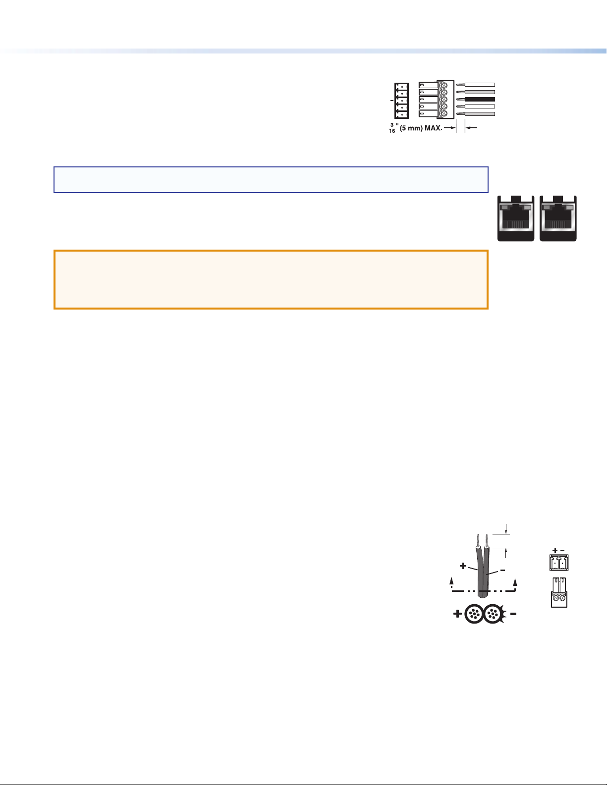
C Over TP connector — Plug an RS-232 or modulated IR device into this
RS-232/IR pass-through port. Wire the cable as shown to the right.
D HDBT/DTP mode switch — Set this 2-position, recessed switch
to congure the output between HDBaseT and DTP modes. When
congured for HDBaseT, use an HDBaseT-compatible receiver. When
OVER TP
Tx/Rx
Pins
RS-232 IR
RxTx
G
RxTx
congured for DTP, use a DTP-compatible receiver.
Step 4 — Run Cables Between Units
NOTE: The DTP T HWP 4K 231 D and DTP T HWP 4K 331 D products can transmit video, control, and
audio (if applicable) signals up to 230 feet (70 m) and 330 feet (100 m), respectively.
Connect the rear panel transmitter output (E) to the rear panel receiver input using shielded twisted pair
(STP) cable.
For optimal performance, Extron highly recommends the following:
ATTENTION:
• Do not use Extron UTP23SF-4 Enhanced Skew-Free AV UTP cable or STP201 cable.
• N’utilisez pas le câble AV Skew-FreeUTP version améliorée UTP23SF d’Extron ou le
câble STP201.
z RJ-45 termination with STP cable must comply with TIA/EIA T 568B wiring standard for all connections. For more
information on cable wiring and termination, see the full product user guide at www.extron.com.
z Use shielded twisted pair cable, 24 AWG solid conductor or better, with a minimum cable bandwidth of 400 MHz.
z Use shielded RJ-45 plugs to terminate the cable.
z Limit the use of RJ-45 patches. Overall transmission distance capabilities vary depending on the number of patches
used. If possible, limit the number of patches to only 1 or 2 total.
z If RJ-45 patches must be used in the system, shielded CAT 6 (or better) patches are recommended.
Connected RS-232
and IR Device Pins
Transmit pin on connected unit
Receive pin on connected unit
Ground
Transmit pin on connected unit
Receive pin on connected unit
SIG LINK
OUT
Rear Panel TP Ports
SIG LINK
IN
Step 5 — Connect Outputs from the Receiver
The DTP T HWP 4K D Series products are compatible with DTP 230 and DTP 330 receivers (sold separately).
a. HDMI output connector — Connect an HDMI cable between this port and the input port of the display.
b. Audio output — Connect a stereo audio device to this 3.5 mm mini stereo jack to receive the passed through
unbalanced audio.
c. RS-232/IR Over TP connector — Plug an RS-232 or modulated IR device into the RS-232/IR pass-through port.
Wire the connector as shown in step 3.
Step 6 — Power the Units
When the unit is congured for DTP mode via the rear panel switch (D), the unit can be powered
either locally, with the included external 12 VDC power supply, or over the DTP line by a locally
powered receiver or switcher.
When congured for HDBaseT mode, remote power capability is disabled, and the unit must be
powered locally.
To power the unit locally in either mode, wire the 2 pole captive screw connector for the included
external 12 VDC power supply as shown at right. Plug the power supply captive screw connector
into F.
Step 7 — Final Installation
a. Make all connections and test the system for satisfactory operation.
b. At the power outlet, unplug the power supply.
c. Mount the transmitter or receiver into the wall box and attach the supplied decorator-style faceplate to the unit.
d. At the power outlet, reconnect the power supply. This powers up both units (unless in HDBaseT mode).
2
(5 mm) Max.
Smooth
SECTION A–A
Power Supply
3/16"
Ridges
AA
Captive Screw
Connector
Page 3
DTP T HWP 4K D Series • Setup Guide (Continued)
LOCAL OUT
HDMI IN
AUDIO IN
E
Tx Rx Tx Rx
RS-232 IR
G
HDBT
DTP
OVER TP
OUT
POWER
12V
0.7A MAX
DTP T HWP 4K D Series
Rear Panel
F
C
D
E
Operation
After all devices are powered up, the system is fully operational. See the denitions of the power indications below.
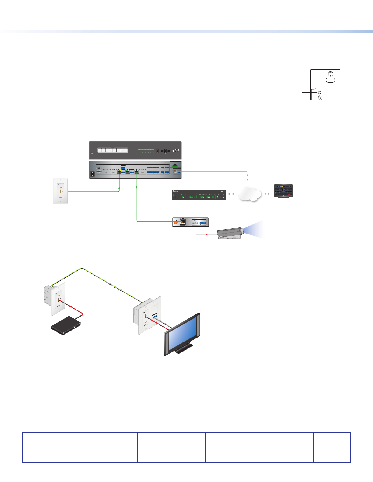
Transmitter Power Indicator
A Power LED — This two-color front panel LED on all DTP T HWP 4K D Series model transmitters
lights to indicate signal and power status as follows:
Amber — The unit is receiving power but no signal on the HDMI input.
Green — The unit is receiving power and a signal is present on the HDMI input.
Application Diagrams
The following gures show typical applications for the DTP T HWP 4K D Series transmitters.
OUTPUTS
8
SIG LINK
DTP IN
OVER DTP
RS-232 IR
TxRx TxRxG
SIGNAL
1
HDCP
IN1608 SA
OUTPUTS
C
SIG LINK
DTP OUT
2 3 4 5 6 7 8 A B C
A
B
INPUTS
MENU
ENTER
AUDIO INPUTS
LL1R R
L5R
+48V
HDMI
XTP DTP 24 Cable
MIC/LINE
L2
L4
L6
R
R
R
2
+48V
230 '
DTP HDMI 4K 230 Rx
OUTPUTS
12
VARIABLE
LR
VOLUME
IN1608
SCALING PRESENTATION SWITCHER
AMPLIFIED OUTPUT
2x25W(8Ω)/2x50W(4Ω)
L3R
CLASS 2 WIRING
REMOTE
LAN
RESET
RS-232
TxRx
IPCP 505
R
IPCP 505
POWER
12V
0.7A MAX
G
Ethernet
COM
RTS
FLEX
RELAY
5162314
738
100
eBUS
I/O
ACT LIMIT
2
4
LINK
IR
ACT
OVER
Network
TLP 1000TV
IR/S
CTS
4
RX
5162738
OUTPUTS
AUDIO
LR
SIG LINK
SWITCHED
DTP IN
12VDC
2
314
LIMIT
TXRXTX
OVER
1 2345678
HDMI
Projector
CONFIG
Extron
100-240V ~ -- A MAX
50/60 Hz
AUDIO IN
HDMI IN
Extron
DTP T HWP 4K 231 D Tx
Transmitte r
IN1608
XTP DTP 24 Cable
230 '
INPUTS
1 2 3 4 5 6 7 8
INPUTS
1
5
3
CONFIGURABLE
2
HDMI
HDMI
6
4
OVER DTP
RS-232 IR
TxRx TxRxG
7
SIG LINK
OVER DTP
RS-232 IR
DTP IN
TxRx TxRxG
A
DTP T HWP 4K D Series
Front Panel
Figure 1. A Typical DTP T HWP 4K D Series Application in a Larger System
Extron
AUDIO IN
DTP T HWP 4K 231 D Tx
HDMI IN
Transmitter
HDMI
Blu-ray Player
Figure 2. A Typical DTP T HWP 4K D Series Point-to-Point Application
Extron Headquarters
+800.633.9876 Inside USA/Canada Only
Extron USA - West Extron USA - East
+1.714.491.1500 +1.919.850.1000
+1.714.491.1517 FAX +1.919.850.1001 FAX
© 2017 Extron Electronics All rights reserved. All trademarks mentioned are the property of their respective owners. www.extron.com
CATx Cable
up to 230' (70 m)
Extron
DTP HDMI 4K 230 D Rx
Receiver
Extron Europe
+800.3987.6673
Inside Europe Only
+31.33.453.4040
+31.33.453.4050 FAX
OUTPUTS
IR
OVER DTP
-232
RS
TxRx G Tx Rx
AUDIO
HDMI
Flat Panel
Display
Extron Asia
+65.6383.4400
+65.6383.4664 FAX
RS-232
Extron Japan
+81.3.3511.7655
+81.3.3511.7656 FAX
Extron China
+86.21.3760.1568
+86.21.3760.1566 FAX
Extron Middle East
+971.4.299.1800
+971.4.299.1880 FAX
Extron Australia
+61.8.8113.6800
+61.8.8351.2511 FAX
Extron India
1800.3070.3777
(Inside India Only)
+91.80.3055.3777
+91.80.3055.3737 FAX
68-2544-50 Rev. B
05 17
 Loading...