

Extron DTP2 T 204 User Manual
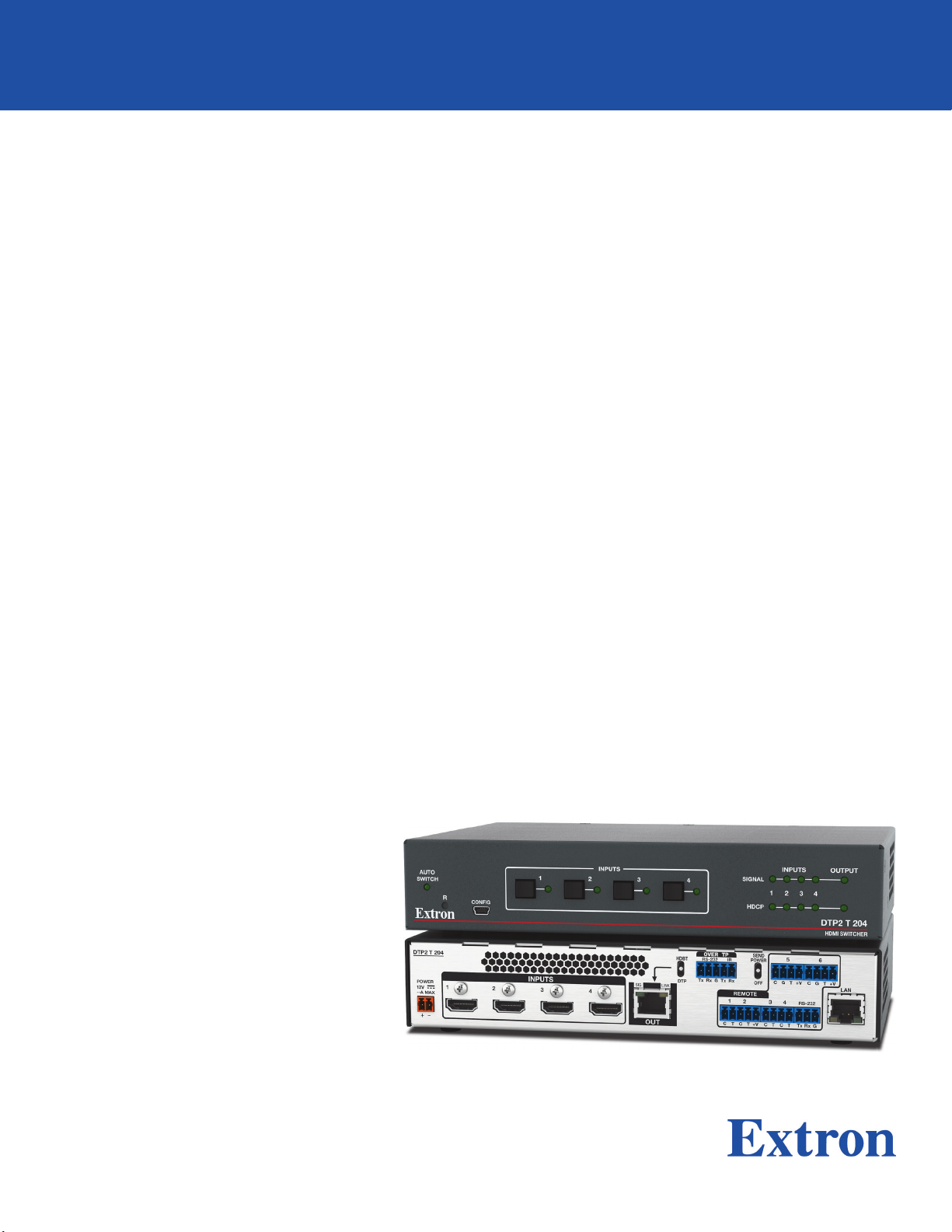
DTP2 T 204
Four Input Switcher with
Integrated DTP2 Transmitter
User Guide
DTP Switching Transmitters
68-3277-01 Rev. A
09 20
Safety Instructions
Safety Instructions • English
WARNING: This symbol, , when used on the product, is intended to
alert the user of the presence of uninsulated dangerous voltage within
the product’s enclosure that may present a risk of electric shock.
ATTENTION: This symbol, , when used on the product, is intended
to alert the user of important operating and maintenance (servicing)
instructions in the literature provided with the equipment.
For information on safety guidelines, regulatory compliances, EMI/EMF
compatibility, accessibility, and related topics, see the Extron Safety and
Regulatory Compliance Guide, part number 68-290-01, on the Extron website,
www.extron.com.
Sicherheitsanweisungen • Deutsch
WARUNG: Dieses Symbol auf demProdukt soll den Benutzer darauf
aufmerksam machen, dass im Inneren des Gehäuses dieses Produktes
gefährliche Spannungen herrschen, die nicht isoliert sind und die einen
elektrischen Schlag verursachen können.
VORSICHT: Dieses Symbol auf dem Produkt soll dem Benutzer in
der im Lieferumfang enthaltenen Dokumentation besonders wichtige
Hinweise zur Bedienung und Wartung (Instandhaltung) geben.
Weitere Informationen über die Sicherheitsrichtlinien, Produkthandhabung,
EMI/EMF-Kompatibilität, Zugänglichkeit und verwandte Themen finden Sie in den
Extron-Richtlinien für Sicherheit und Handhabung (Artikelnummer
68-290-01) auf der Extron-Website, www.extron.com.
Instrucciones de seguridad • Español
ADVERTENCIA: Este símbolo, , cuando se utiliza en el producto, avisa
al usuario de la presencia de voltaje peligroso sin aislar dentro del
producto, lo que puede representar un riesgo de descarga eléctrica.
ATENCIÓN: Este símbolo, , cuando se utiliza en el producto,
avisa al usuario de la presencia de importantes instrucciones de
uso y mantenimiento estas estan incluidas en la documentación
proporcionada con el equipo.
Para obtener información sobre directrices de seguridad, cumplimiento
de normativas, compatibilidad electromagnética, accesibilidad y temas
relacionados, consulte la Guía de cumplimiento de normativas y seguridad de
Extron, referencia 68-290-01, en el sitio Web de Extron, www.extron.com.
Instructions de sécurité • Français
AVERTISSEMENT : Ce pictogramme, , lorsqu’il est utilisé sur le
produit, signale à l’utilisateur la présence à l’intérieur du boîtier du
produit d’une tension électrique dangereuse susceptible de provoquer
un choc électrique.
ATTENTION : Ce pictogramme, , lorsqu’il est utilisé sur le produit,
signale à l’utilisateur des instructions d’utilisation ou de maintenance
importantes qui se trouvent dans la documentation fournie avec
l’équipement.
Pour en savoir plus sur les règles de sécurité, la conformité à la réglementation,
la compatibilité EMI/EMF, l’accessibilité, et autres sujets connexes, lisez les
informations de sécurité et de conformité Extron, réf. 68-290-01, sur le site
Extron, www.extron.com.
Copyright
© 2020 Extron. All rights reserved. www.extron.com
Trademarks
All trademarks mentioned in this guide are the properties of their respective owners.
The following registered trademarks (®), registered service marks (SM), and trademarks (TM) are the property of RGBSystems, Inc. or Extron (see the
current list of trademarks on the Terms of Use page at www.extron.com):
Registered Trademarks (
Extron, Cable Cubby, ControlScript, CrossPoint, DTP, eBUS, EDID Manager, EDID Minder, eLink, Flat Field, FlexOS, Glitch Free, Global
Configurator, GlobalScripter, GlobalViewer, Hideaway, HyperLane, IPIntercom, IPLink, KeyMinder, LinkLicense, LockIt, MediaLink, MediaPort,
NAV, NetPA, PlenumVault, PoleVault, PowerCage, PURE3, Quantum, ShareLink, Show Me, SoundField, SpeedMount, SpeedSwitch, StudioStation,
SystemINTEGRATOR, TeamWork, TouchLink, V-Lock, VideoLounge, VN-Matrix, VoiceLift, WallVault, WindoWall, XPA, XTP, XTPSystems, and ZipClip
Registered Service Mark
(SM)
: S3 Service Support Solutions
Trademarks (™
AAP, AFL (Accu-RATEFrameLock), ADSP(Advanced Digital Sync Processing), Auto-Image, AVEdge, CableCover, CDRS(ClassD Ripple
Suppression), Codec Connect, DDSP(Digital Display Sync Processing), DMI (DynamicMotionInterpolation), DriverConfigurator, DSPConfigurator,
DSVP(Digital Sync Validation Processing), EQIP, Everlast, FastBite, Flex55, FOX, FOXBOX, IP Intercom HelpDesk, MAAP, MicroDigital, Opti-Torque,
PendantConnect, ProDSP, QS-FPC(QuickSwitch Front Panel Controller), RoomAgent, Scope-Trigger, SIS, SimpleInstructionSet, Skew-Free,
SpeedNav, Triple-Action Switching, True4K, True8K, Vector™ 4K, WebShare, XTRA, and ZipCaddy
®
)
)

FCC Class A Notice
This equipment has been tested and found to comply with the limits for a Class A digital
device, pursuant to part15 of the FCC rules. The ClassA limits provide reasonable
protection against harmful interference when the equipment is operated in a commercial
environment. This equipment generates, uses, and can radiate radio frequency energy and,
if not installed and used in accordance with the instruction manual, may cause harmful
interference to radio communications. Operation of this equipment in a residential area is
likely to cause interference. This interference must be corrected at the expense of the user.
ATTENTION:
• The Twisted Pair Extension technology works with unshielded twisted pair (UTP)
• La technologie extension paires torsadées fonctionne avec les câbles paires
NOTES:
• This unit was tested with shielded I/O cables on the peripheral devices. Shielded
• For more information on safety guidelines, regulatory compliances, EMI/EMF
or shielded twisted pair (STP) cables; but to ensure FCC Class A and CE
compliance, STP cables and STP Connectors are required.
torsadées blindées(UTP) ou non blindées(STP). Afin de s’assurer de la
compatibilité entre FCC ClasseA et CE, les câbles STP et les connecteurs STP
sont nécessaires.
cables must be used to ensure compliance with FCC emissions limits.
compatibility, accessibility, and related topics, see the Extron Safety and
Regulatory Compliance Guide on the Extron website.
VCCI-A Notice
この装置は、クラスA情報技術装置です。 この装置を家庭環境で使用すると、電波妨害を引き
起こすことがあります。 その場合には使用者が適切な対策を講ずるよう要求されることがあります。
VCCI-A
Conventions Used in this Guide
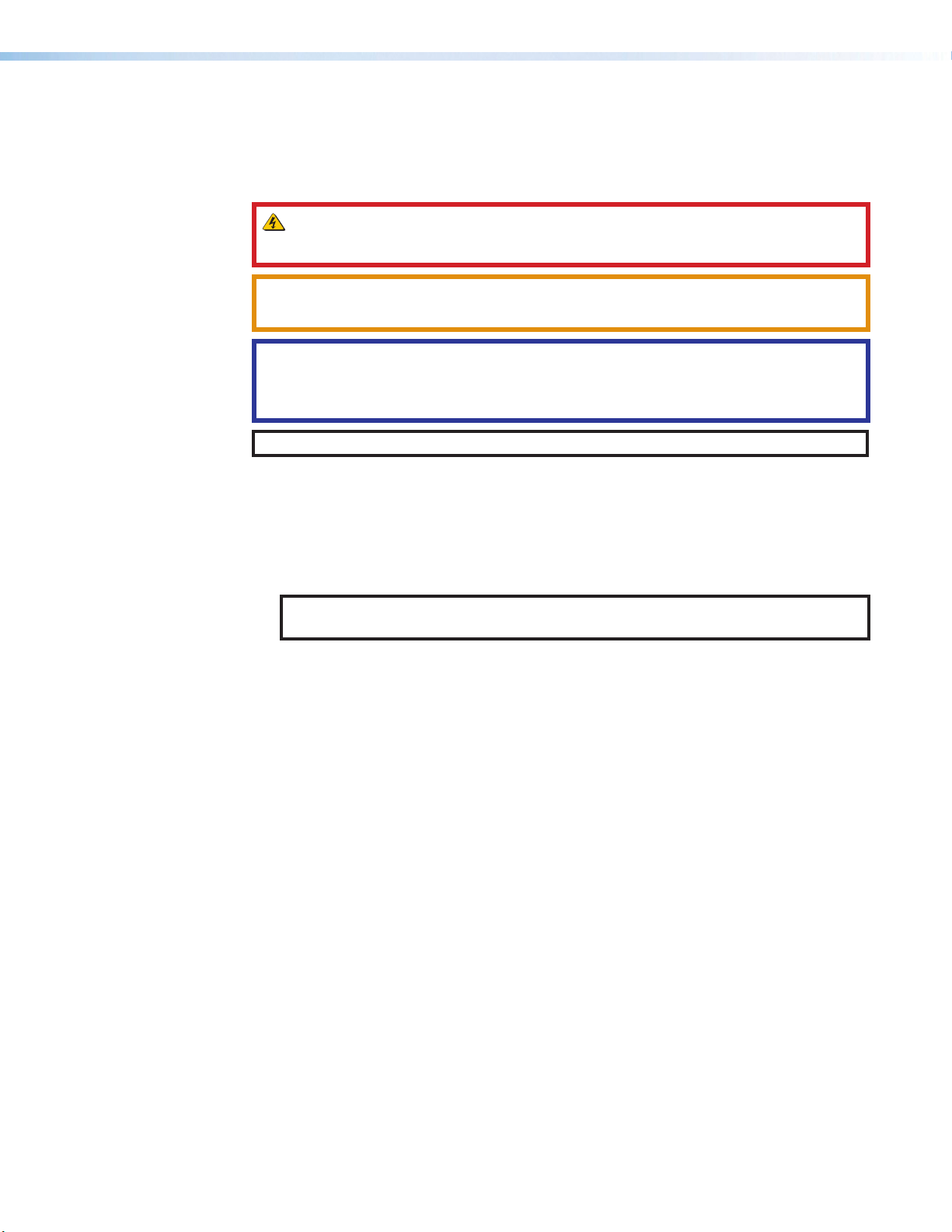
Notifications
The following notifications are used in this guide:
WARNING: Potential risk of severe injury or death.
AVERTISSEMENT : Risque potentiel de blessure grave ou de mort.
CAUTION: Risk of minor personal injury.
ATTENTION : Risque de blessuremineure.
ATTENTION:
• Risk of property damage.
• Risque de dommages matériels.
NOTE: A note draws attention to important information.
Software Commands
Commands are written in the fonts shown here:
^AR Merge Scene,,0p1 scene 1,1 ^B 51 ^W^C.0
[01] R 0004 00300 00400 00800 00600 [02] 35 [17] [03]
E X! *X1&* X2)* X2#* X2! CE}
NOTE: For commands and examples of computer or device responses used in this
guide, the character “0” is the number zero and “O” is the capital letter “o.”
Computer responses and directory paths that do not have variables are written in the font
shown here:
Reply from 208.132.180.48: bytes=32 times=2ms TTL=32
C:\Program Files\Extron
Variables are written in slanted form as shown here:
ping xxx.xxx.xxx.xxx —t
SOH R Data STX Command ETB ETX
Selectable items, such as menu names, menu options, buttons, tabs, and field names are
written in the font shown here:
From the File menu, select New.
Click the OK button.
Specifications Availability
Product specifications are available on the Extron website, www.extron.com.
Extron Glossary of Terms
A glossary of terms is available at http://www.extron.com/technology/glossary.aspx.


Contents
Introduction ................................................1
About this Guide .................................................. 1
About the DTP2 T 204 Switcher .......................... 1
Features .............................................................. 1
Application Diagrams ........................................... 4
Installation .................................................. 5
Installation Overview ............................................ 5
Rear Panel Features ............................................ 6
Wiring the Power Connector .............................. 11
Wiring for RS-232 Control ................................. 12
Wiring the Contact/Tally Connectors .................. 13
Connecting Using a Show Me (SM Series)
Cable ............................................................ 14
Wiring for Over TP RS-232 and IR Control ......... 14
LockIt HDMI Lacing Bracket Installation ............. 16
Operation..................................................17
Front Panel Features .......................................... 17
Operations......................................................... 18
Powering on the Switcher .............................. 18
Selecting an Input .......................................... 19
Auto-input Switching ..................................... 19
EDID Minder .................................................. 20
Resetting ....................................................... 21
Contact/Tally Modes ...................................... 23
Remote Configuration and Control .............24
Using Simple Instruction Set (SIS) Commands ... 24
Host-to-switcher Communications ................ 24
Switcher-initiated Messages .......................... 24
Error Responses ............................................ 25
Using the Command and Response Table ..... 26
Symbol Definitions ......................................... 26
Command and Response Table for SIS
Commands ...................................................... 31
Command and Response Table for CEC
Communications SIS Commands ..................... 43
Downloading the DTP2 T 204 Firmware ............ 45
Accessing the Product Configuration
Software ........................................................... 47
Downloading and Installing PCS .................... 47
Starting PCS .................................................. 50
Internal Web Page ..................................... 51
Accessing the Web Page ................................... 51
Web Page Overview .......................................... 52
Communication Settings Panel ...................... 52
Input Status Panel ......................................... 53
Output Status Panel ...................................... 53
Date/Time Settings Panel .............................. 54
Device Info Panel ........................................... 55
Passwords Panel ........................................... 56
Configure This Device Panel .......................... 57
Mounting ..................................................58
Tabletop Use ..................................................... 58
Rack Mounting .................................................. 58
UL Rack Mounting Guidelines ........................ 58
Furniture Mounting ............................................ 58
viiDTP2 T 204 Switcher • Contents

DTP2 T 204 Switcher • Contents viii

Introduction
This section gives an overview of the Extron DTP2 T 204 switcher. Topics include:
• About this Guide
• About the DTP2 T 204 Switcher
• Features
• Application Diagrams
About this Guide
This guide describes the DTP2 T 204 switchers and discusses how to install, configure, and
operate them.
In this guide, the terms “DTP2 T 204” and “switcher” are used interchangeably to refer to
the DTP2 T 204 switcher.
About the DTP2 T 204 Switcher
Features
The Extron DTP2 T 204 is a four-input switcher for sending HDMI and control up to 330 feet
(100 meters) over a shielded CATx cable to an Extron DTP-enabled product. It has four
HDMI inputs and a DTP2 output. The DTP2 T 204 supports video signals at resolutions up
to 4K @ 60 Hz at 4:4:4 chroma sampling and complies with HDCP 2.3. Ethernet remote
control and contact/tally connections facilitate integration in professional environments.
Integrator-friendly features include EDID Minder, auto-switching between inputs, and
bidirectional RS-232 and IR pass-through for remote AV device control. The half-rack
enclosure enables discreet placement within lecterns, beneath tables, or wherever needed
to meet application requirements.
The DTP2 T 204 provides reliable switching and transmission of HDMI video at data rates
up to 18 Gbps, along with support for HDR, Deep Color up to 12-bit, 3D, and embedded
HD lossless audio formats. For simplified operation, it can be configured to automatically
switch between the sources. The DTP2 output can be configured to send video and
embedded audio, plus bidirectional RS-232 and IR signals, to an HDBaseT-enabled display.
• Transmits HDMI and control up to 330 feet (100 meters) over a shielded CATx
cable
• Inputs — Four HDMI female type-A connectors
• Output — One DTP2 twisted pair output on RJ-45
• Supports computer and video resolutions up to 4K @ 60 Hz at 4:4:4 chroma
sampling — Support of 4K @ 60 Hz at 4:4:4 chroma sampling requires connection to
a matching DTP2 product.
• Auto-switching between inputs — Multiple switching priority modes are available,
including last-connected input and user-selectable priority.
DTP2 T 204 Switcher • Introduction 1

• Supports HDMI 2.0b specification features include data rates up to 18 Gbps,
HDR, Deep Color up to 12-bit, 3D, and HD lossless audio formats
• Support for High Dynamic Range (HDR) video — Enables greater contrast range
and wider color gamut by providing the necessary video bandwidth, color depth, and
metadata interchange capability for HDR video.
• HDCP 2.3 compliant — Ensures display of content-protected 4K video media and
interoperability with other HDCP compliant devices.
• Remote power capability — Can be remotely powered by a DTP2-enabled product
over the twisted pair connection. Can also be configured to provide power to the
connected DTP2 receiver product.
• Ethernet monitoring and control — Enables control and proactive monitoring over a
network.
• Extron XTP DTP 24 shielded twisted pair cable is strongly recommended for
optimal performance
• Compatible with CATx shielded twisted pair cable — Fully supports a maximum
transmission distance of 330 feet (100 meters) for all compatible resolutions when used
with CATx shielded twisted pair cable. Shielded twisted pair cabling with solid center
conductor sizes of 24 AWG or better is recommended for optimal performance.
• DTP2 output is compatible with HDBaseT-enabled devices — The DTP2 output
can be configured to send video and embedded audio, plus bidirectional RS-232 and IR
signals to an HDBaseT-enabled display.
• Bidirectional RS-232 and IR pass-through for AV device control — Bidirectional
RS-232 control and IR signals can be transmitted alongside the video signal, allowing
remote AV devices to be controlled without the need for additional cabling.
• RS-232 insertion from the Ethernet control port — Saves system resources and
simplifies installation by enabling a control processor to access remote RS-232 devices
over Ethernet.
• CEC insertion — A control processor can insert CEC commands via SIS commands
to control devices connected at the HDMI output.
• Supports multiple embedded audio formats — Compatible with a broad range of
multi-channel audio signals, providing reliable operation with HDMI sources.
• Compatible with all DTP receivers and DTP-enabled products — Enables mixing
and matching with desktop and wallplate receivers, as well as other DTP-enabled
products to meet application requirements.
• User-selectable HDCP authorization — Allows individual inputs to appear
HDCP-compliant or non-HDCP compliant to the connected source, which is beneficial
if the source automatically encrypts all content when connected to an HDCP-compliant
device. Protected material is not passed in non-HDCP mode.
• Comprehensive EDID management — Use PCS to access EDID Minder for setting
video input EDID, capturing EDID from connected displays, or uploading custom EDID
files. Proper EDID management ensures that sources and displays are easily integrated
into a system resulting in optimized system operation. Free, downloadable EDID
Manager 2.0 software is available for advanced EDID editing and creating custom EDID
files.
• EDID Minder automatically manages EDID communication between connected
devices — Ensures that all sources power up properly and reliably output content for
display.
DTP2 T 204 Switcher • Introduction 2

• Key Minder continuously verifies HDCP compliance — Key Minder authenticates
and maintains continuous HDCP encryption between input and output devices to
ensure quick and reliable switching in professional AV environments, while enabling
simultaneous distribution of a single source to multiple displays.
• HDCP authentication and signal presence confirmation — Provides real-time
verification of HDCP status for each digital video input and output. This allows for easy
signal and HDCP verification through front panel LEDs, RS-232, USB, or Ethernet,
providing valuable feedback to a system operator or helpdesk support staff.
• HDCP Visual Confirmation — When HDCP-encrypted content is transmitted to
a non-HDCP compliant display, a full screen green signal is sent to the display for
immediate visual confirmation that protected content cannot be viewed on that display.
• HDMI to DVI Interface Format Correction — Automatically enables or disables
embedded audio and InfoFrames, and sets the correct color space for proper
connection to HDMI and DVI displays.
• Automatic color bit depth management — The DTP2 T 204 automatically adjusts
color bit depth based on the display EDID, preventing color compatibility conflicts
between source and displays.
• Output muting control — Enables HDMI output muting at any time.
• Front panel security lockout — Locks all front panel functions. All functions, however,
are available through USB, RS-232, and Ethernet control.
• Built-in web pages — Enables the use of a standard browser for device monitoring
and troubleshooting over an intuitive web interface.
• RS-232 control port — Enables the use of serial commands for integration into a
control system. Extron products use the SIS command protocol, a set of basic ASCII
commands that allow for quick and easy programming.
• Contact closure remote control with tally output — Allows for remote selection of
an input channel, while a tally output provides +5 VDC to light an LED to indicate the
currently selected input. The contact and tally ports can be configured for independent
use when the DTP2 T 204 is connected to an external control processor.
• Compatible with TeamWork SM Series Cables — SM cables provide convenient
connectivity and user input selection and control for TeamWork Collaboration Systems.
See the TeamWork System Builder to create a customized system for your collaboration
environment.
• Front panel USB configuration port — Enables easy configuration without the need
to access the rear panel.
• LED indicators for signal presence, HDCP, power, and link status — Provides
visual indication of system status for real-time feedback and monitoring of key
performance parameters.
• RJ-45 signal and link LED indicators for DTP port — Provides a means for
validating signal flow and operation, allowing quick identification of connectivity issues.
• Easy setup and commissioning with PCS — Enables configuration of multiple
products using a single software application.
• 1U high, half rack width metal enclosure
• Includes LockIt HDMI cable lacing brackets
• External Extron Everlast power supply included — (Replacement part number
70-769-01) Provides worldwide power compatibility with high-demonstrated reliability
and low power consumption. The Extron Everlast Power Supply is covered by a 7-year
parts and labor warranty.
DTP2 T 204 Switcher • Introduction 3
Application Diagrams
r
Extron
Extron
HDMI
Sh
PC
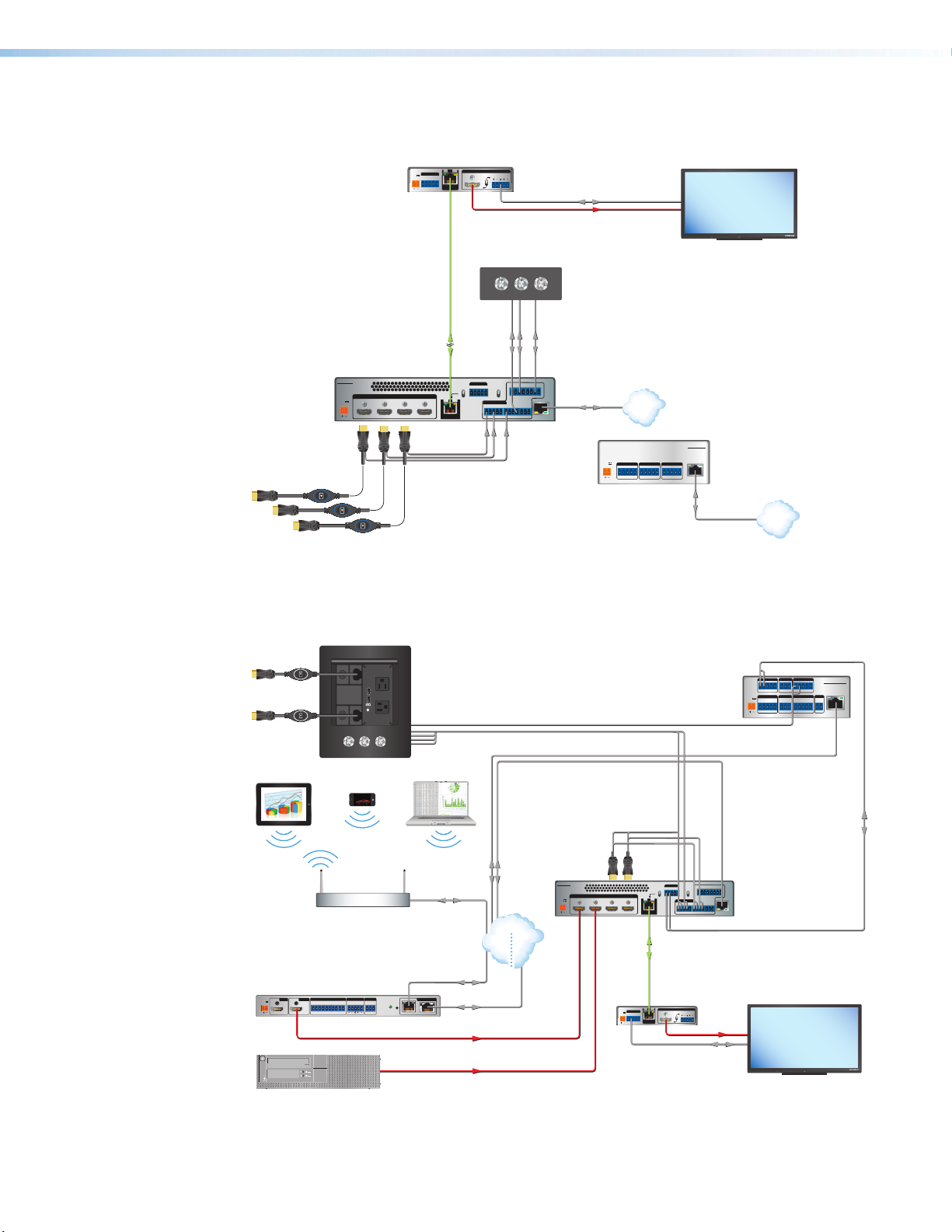
The following diagram shows a typical application for a DTP2 T 204.
DTP2 R 211
Receiver
SIG LINK
POWER
OVER DTP2
12V
--A MAX
RS-232 IR
TxRx Tx RxG
OUTPUTS
AUDIO
L
DTP2 IN
R
RS-232
MODEL 80
HDMI
FLAT PANEL
G
G
Tx Rx RTSCTS
Flat Panel Display
IPL PRO S3
Extron
IPL Pro S3
IP Link Pro
LAN / PoE
Control Processo
Ethernet
LAN
Extron
DTP2 T 204
Transmitter
Extron
HDMI SM
Show Me Cables
SHARE
CATx Cable
up to 330' (100 m)
DTP2 T 204
POWER
12V
--AMAX
SHARE
INPUTS
1 2 3 4
SHARE
HDMI
ON/OFF/MUTE Control
ON OFF MUTE
OVER TP2
SEND
RS-232IR
HDBT
POWER
RxTxG
RxTx
OFF
DTP
SIG LINK
REMOTE
12 34
C+VTCTCTCT
OUT
Extron
CCR 30
Contact Closure Remote
with Three LED Switches
5
G6C+VTGC+VT
LAN
RS-232
RxTx
Ethernet
G
POWER
12V
0.3A MAX
Tx Rx RTSCTS
LAN
COM 1 COM 2 COM 3
Tx Rx RTSCTS
G
Figure 1. DTP2 T 204 Application Diagram with IPL Pro and DTP2 R 211
ow Me Cables
COM 1
COM 2
DIGITAL I/O
G
Extron
USB CHARGER
125 VAC. 50-60 Hz 12A MAX
Cable Cubby 500 CCB
PRESS PRESS
Tablet
Smartphone
Cable Access Enclosure
PCSHARELINKON/OFF
Laptop
Extron
IPCP Pro 250
Control Processor
Tx Rx RTSCTS
POWER
VOL
12V
VCG
1A MAX
IPCPPRO250
G
Tx Rx
1 2 3 4G
RELAYS
eBUS
IR/S
12C
+V+S-SG
SG
PWROUT =6W
LAN
RS-232
Extron
ShareLink Pro 1000
Wireless Collaboration
Gateway
POWER
OUTPUT
INPUT
12V
1.7A MAX
1234
WiFi
HDMI HDMI
1
CT2CT3CT4CTG+V
Wireless
Facility/Room
Wireless Access Point
COM
OUTPUT
CONTACT / TALLY
AUDIO
RS-232
RESET
L
R
TxRx G
A/PoE+B
Ethernet Ethernet
Ethernet
Ethernet
LAN
Ethernet
HDMI
HDMI
Private
Network
Public
DTP2 T 204
POWER
12V
1 2 3 4
--AMAX
OVER TP2
SEND
5
RS-232 IR
HDBT
INPUTS
POWER
OVER DTP2
12V
--A MAX
RS-232 IR
TxRx Tx RxG
POWER
RxTxG
RxTx
OFF
DTP
SIG LINK
REMOTE
12 34
C+VTCTCTCT
OUT
CATx Cable
up to 330' (100 m)
Extron
DTP2 R 211
Receiver
SIG LINK
OUTPUTS
AUDIO
L
DTP2 IN
R
RS-232
G
RxTx
HDMI
G6C+VTGC+VT
LAN
Extron
DTP2 T 204
Switcher
Display
MODEL 80
RS-232
FLAT PANEL
Figure 2. DTP2 T 204 Application with ShareLink and IPCP Pro
DTP2 T 204 Switcher • Introduction 4

Installation
This section describes the installation and setup of the DTP2 T 204 switchers. Topics
include:
• Installation Overview
• Rear Panel Features
• Wiring the Power Connector
• Wiring for RS-232 Control
• Wiring the Contact/Tally Connectors
• Wiring for Over TP RS-232 and IR Control
• LockIt HDMI Lacing Bracket Installation
Installation Overview
To install and set up the DTP2 T 204 switcher:
1. Turn off all equipment and disconnect it from the power source.
2. (Optional) Mount the switcher on a rack shelf or furniture (see Mounting starting on
page58).
3. Connect HDMI input sources to one or more of the DTP2 T 204 input connectors.
NOTE: LockIt cable lacing brackets, one for each HDMI input connector, are
provided with the DTP2 T 204. These brackets can be used to secure the HDMI
cables to the rear panel connectors to reduce stress on the connectors and
prevent signal loss due to loose cable connections. For information on attaching
the LockIt brackets, see LockIt HDMI Lacing Bracket Installation on
page16).
4. Connect a DTP or HDBaseT compatible output device to the DTP/HDBT OUT
connector.
5. Set the TP mode switch to HDBT (up) or DTP (down).
When the output is configured for DTP mode, remote power is available. When the output
is configured for HDBT mode, remote power is disabled and the switcher and receiver each
require its own 12 VDC power supply.
ATTENTION:
• Position this switch BEFORE connecting the appropriate device to the TP
connector. Failure to comply can damage the endpoint.
• Positionnez le sélecteur AVANT de connecter l’appareil approprié au connecteur
TP. Ne pas respecter cette procédure pourrait endommager le point de connexion.
• Do not connect these devices to a computer data or telecommunications network.
• Ne connectez pas cet appareil à un réseau de télécommunications ou de données
informatiques.
DTP2 T 204 Switcher • Installation 5
6. For IR control and bidirectional over TP RS-232, connect a serial RS-232 signal,
A
B
C
D
E
F
G
H
a modulated IR signal, or both into the 3.5 mm, 5-pole captive screw connector
(see Wiring for Over TP RS-232 and IR Control on page14).
7. Connect the computer to one of the following DTP2 T 204 ports to configure and
control the switcher via SIS commands or PCS (Config and LAN ports only):
• RS-232 port — 3-pole captive screw connector for serial RS-232 control (see
• Config port — USB mini-B connector for USB control
• LAN port — RJ-45 connector for Ethernet control (see LAN (Ethernet) connector
8. Power on the output display.
9. Connect power to the switcher (see Powering on the Switcher on page18).
10. (Optional) Configure the EDID Minder (see EDID Minder on page20).
11. Power on the source devices.
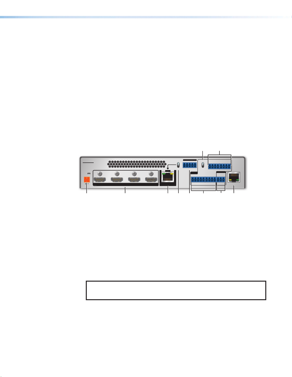
Rear Panel Features
Wiring for RS-232 Control on page12 for connection procedures)
on page9).
I
OVER TP
OUT
HDBT
Tx Rx GTxRx
DTP
LINKSIG
Contact closure input and tally
F
output ports
Remote RS-232 connector
G
LAN (Ethernet) connector
H
Send Power mode switch
I
DTP2 T 204
POWER
1 2 3 4
12V
2.2A MAX
INPUTS
Power input connector
A
HDMI input connectors
B
DTP2 and HDBT output connector
C
TP mode switch
D
Over TP RS-232 and IR connectors
E
RS-232 IR
CONT
12 34
C
SEND POWER
OFF
C
F
56
C
C
TG+V
REMOTE
RS-232
Tx
Rx
G
TTCCT +VT
TG+V
LAN
Figure 3. DTP2 T 204 Rear Panel
Power input connector — Plug the provided external 12 VDC, 3 A power supply into
A
this 2-pole, 3.5 mm captive screw connector and into an AC power outlet.
HDMI input connectors — Connect HDMI video input sources to these female Type A
B
HDMI connectors.
NOTE: LockIt cable lacing brackets are provided with the DTP2 T 204 units. These
brackets secure the HDMI cables to the rear panel connectors and reduce stress
on the connectors, preventing signal loss due to loose cable connections.
DTP2 and HDBT output connector — Connect the input of a DTP2 or HDBaseT
C
compatible device to this RJ-45 connector. The connector contains two LEDs:
• Signal LED — This green LED lights green the unit is outputting a TMDS clock
signal.
• Link LED — This amber LED blinks to indicate a valid link is established between
the units.
DTP2 T 204 Switcher • Installation 6
TP mode switch — Set this switch to DTP or HDBT according to the receiving device
D
connected to the switcher.
ATTENTION:
• Position this switch BEFORE connecting the appropriate device to the DTP
Out connector. Failure to comply can damage the endpoint.
• Positionnez le sélecteur AVANT de connecter l’appareil approprié au
connecteur TP. Ne pas respecter cette procédure pourrait endommager le
point de connexion.
• DTP mode — By default, the output is configured for DTP mode. It supports
remote powering of the DTP receiver, and transmits digital video and audio
and bidirectional IR control. The DTP2T204 transmits signals up to 330feet
(100meters) to any Extron device with a DTP output.
NOTE: If the receiving device is in the Extron DTP2 series or Legacy
DTP series, set this switch to DTP (Down position). The output transmits
HDMI digital video with embedded audio, analog audio, RS-232 and IR,
and remote power up to 330 feet (100 meters) to any Extron device with a
DTP 330 input, or 230 feet (70 meters to devices with a DTP 230 input.
• If the transmitter and receiver are in the Extron DTP2 series, they
can both be powered by one 12 VDC power supply connected to either
unit.
• If the transmitter and receiver are NOT both in the Extron DTP2
series, the transmitter and receiver each requires its own 12 VDC power
supply.
• HDBaseT mode — When the input is configured tor HDBaseT mode, remote
power is disabled. The DTP2T204 transmits digital video, IR control, and
embedded digital audio up to 330feet (100meters) to any third party device with
an HDBaseT output.
E
NOTE: If the receiving device is HDBaseT enabled receiver, set this
switch to HDBT (Up position). The TP output transmits HDMI digital video
with embedded audio along with RS-232 and IR control up to 330 feet
(100 meters) to any device with an HDBaseT input. The transmitter and
receiver each requires its own 12VDC power supply.
Over TP RS-232 and IR connectors — (Optional) Connect a serial RS-232 signal, a
modulated IR signal, or both to this shared 3.5 mm, 5-pole captive screw connector for
bidirectional RS-232 and IR communication (see Wiring for Over TP RS-232 and IR
Control on page14 to wire this connector).
DTP2 T 204 Switcher • Installation 7
Contact closure input and tally output ports — (Optional) To enable control via
C+
F
contact closure, wire a push-button contact closure device to a C (contact) pin of one of
the contact/tally connectors and to a G (ground) pin. To identify the currently selected
input when the front panel buttons are not visible (if desired), connect an indicator
device, such as an LED, to tally output pin T next to the connected Contact pin.
NOTES:
• Contact closure control overrides front panel input selections.
• For contact closure control, auto-switch mode must be off (see Selecting an
Input on page19).
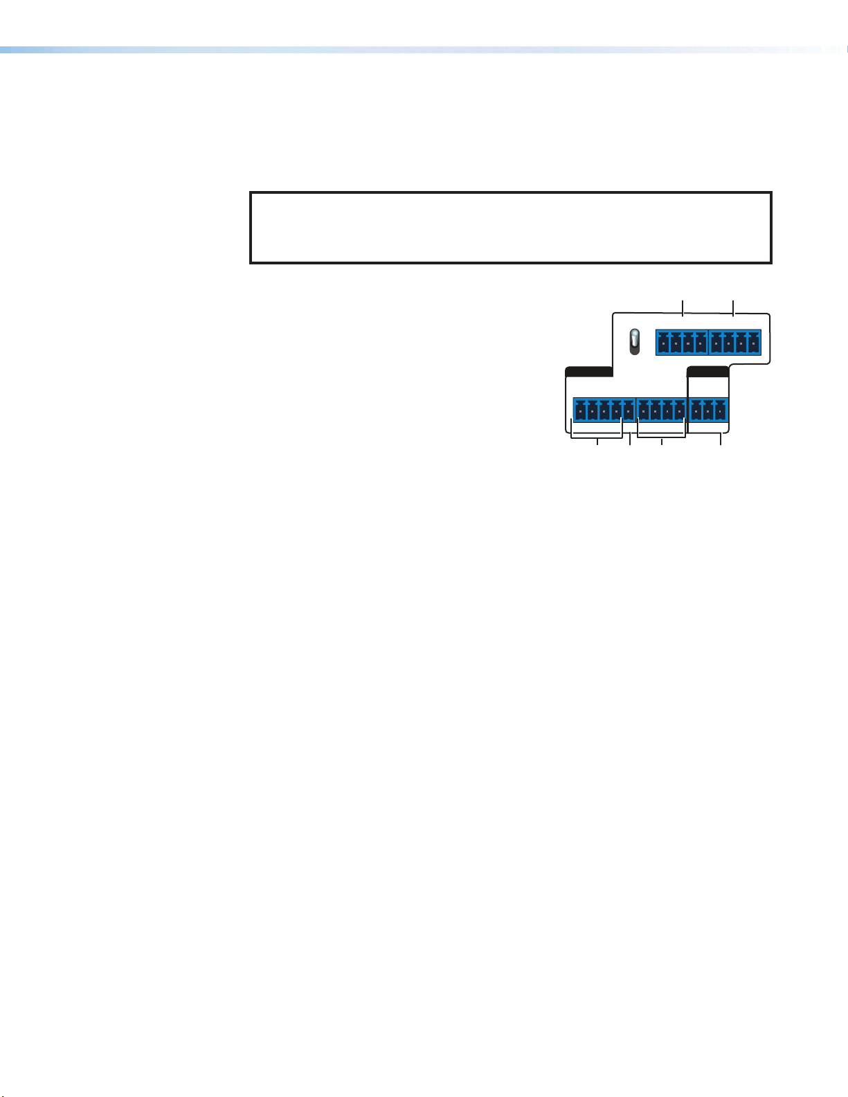
The contact/tally panel (labeled CONT) contains
two rows of contact and tally connectors (see the
image at right):
SEND
POWER
555 666
5
6
• Bottom row — Contains:
G
Contact inputs 1 and 2 — One 5-pole
1
captive screw connector containing two
CONT
OFF
12 34
REMOTE
RS-232
VTGC+VT
pairs of pins labeled C (contact) and T
(tally).
C+VTCTCTCT
G
RxTx
The 5-pole connector also contains a +V
pin, which supplies power to optional tally
111
22
333
444
indicator devices such as LEDs that are
connected to contact inputs.
Contact inputs 3 and 4 — One 4-pole captive screw connector with two
3
more C-T pin pairs.
G pin — A ground pin, located on the 3-pole Remote RS-232 connector.
4
You can connect a contact closure device to this pin and to a C pin of any
contact/tally input.
• Top row — Contains two 4-pole captive screw connectors, each containing a
contact pin, a ground pin, a tally pin, and a +V pin that can be used to power
connected tally indicator devices.
Contact input 5
5
Contact input 6
6
See Wiring the Contact/Tally Connectors on page13 for information on
connecting contact closure and tally indicator devices to the contact/tally ports.
Remote RS-232 connector — Use this 3-pole, 3.5 mm captive screw connector for
G
RS-232 communication with the switcher (including firmware updates).
To enable RS-232 control, connect the Tx (transmit), Rx (receive) and G (ground) pins
to the serial port of your computer or control system (see Wiring for RS-232 Control
on page12).
DTP2 T 204 Switcher • Installation 8
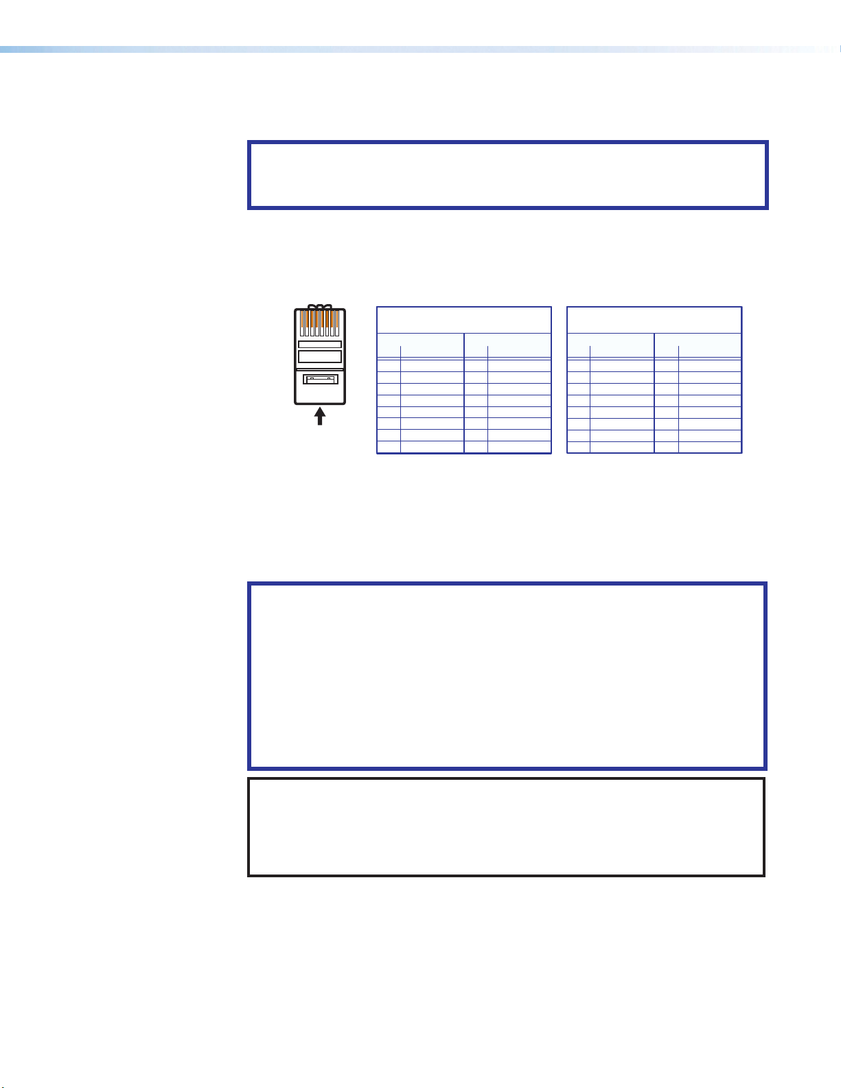
LAN (Ethernet) connector — Use an RJ-45 cable to connect this jack to a LAN for
RJ-45
Connector
Pins:
T568B T568AT568BTIA/EIA-T568B
H
control of the switcher via Ethernet.
ATTENTION:
• Do not connect this device to a telecommunications network.
• Ne connectez pas cet appareil à un réseau de télécommunications.
• Use a straight-through cable for connection to a switch, hub, or router.
• Use a crossover cable or a straight-through cable for connection directly to a PC.
Wire the connector as shown in figure 4.
12345678
Crossover Cable
(for direct connection to a PC)
Insert Twisted
Pair Wires
Straight-through Cable
(for connection to a switch, hub, or router)
End 1 End 2
Pin Wire Color Pin Wire Color
1 white-orange 1 white-orange
2 orange 2 orange
3 white-green 3 white-green
4 blue 4 blue
5 white-blue 5 white-blue
6 green 6 green
7 white-brown 7 white-brown
8 brown 8 brown
End 1 End 2
Pin Wire Color Pin Wire Color
1 white-orange 1 white-green
2 orange 2 green
3 white-green 3 white-orange
4 blue 4 blue
5 white-blue 5 white-blue
6 green 6 orange
7 white-brown 7 white-brown
8 brown 8 brown
Figure 4. Wiring for Ethernet Control
Send Power mode switch — In a DTP2 transmitter to DTP2 receiver configuration,
I
set this toggle switch to the Up (Send Power) position on the powered DTP2 unit to
enable sending remote power to the far end. Set the toggle switch to the Down (Off)
position on the DTP2 unit receiving power.
ATTENTION:
• The DTP2T 204 is configured to output power to DTP2 models only. If
connected to a non-DTP2 device, set the SEND POWER toggle switch
to the Off (Down) position. Failure to turn the power OFF will damage the
connected non-DTP2 device (see figure5 on the next page).
• Le DTP2T 204 est configuré pour fournir une alimentation aux modèles
DTP2 uniquement. S’il est connecté à un autre appareil, veuillez positionner
l’interrupteur à bascule sur « Off » (Down). Si l’interrupteur n’est pas positionné
sur Off, vous risquez d’entraîner la défaillance de l’appareil non DTP2 connecté
(voir figure5).
NOTES:
• When the output is configured for DTP mode, remote power is available only
if both the transmitter and the receiver are from the DTP2 series.
• When the output is configured for HDBT mode, remote power is not available
and both the transmitter and receiver require their own 12 VDC power supply.
DTP2 T 204 Switcher • Installation 9
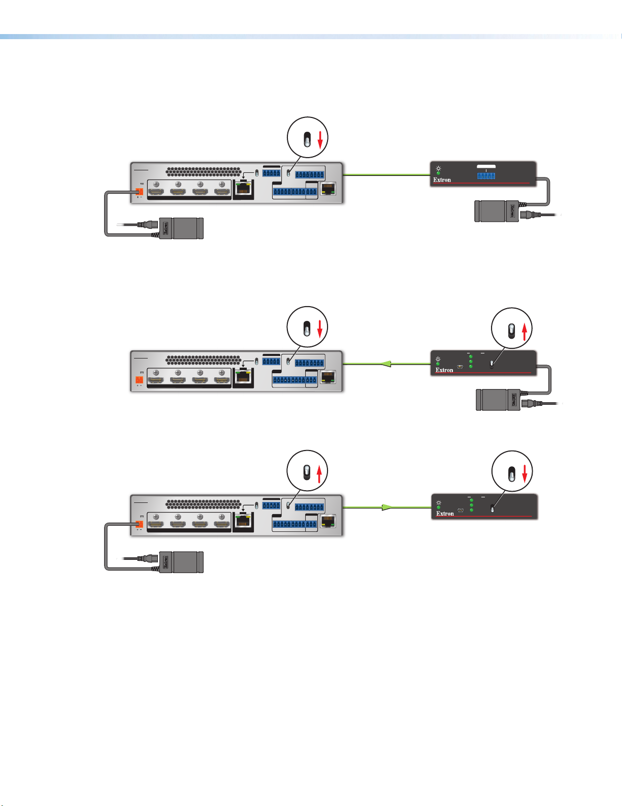
Figure 5 shows examples of connections for Send Power switch settings.
Power Supply
Extron
DTP2 T 204
Transmitter
DTP2 T 204
POWER
12 34
12V
2.0A MAX
INPUTS
Local
Power Supply
Extron
DTP2 T 204
Transmitter
DTP2 T 204
POWER
12 34
12V
2.0A MAX
INPUTS
DTP Endpoint Connected to a DTP2 Endpoint
OFF
SEND POWER
OFF
LAN
No Remote Power
CATx Cable
up to 330' (100 m)
OVER TP
HDBT
SEND POWER
RS-232IR
Tx Rx GTxRx
DTP
LINKSIG
OUT
OFF
CONT
12 34
C
C
56
C
TG+V
REMOTE
RS-232
Tx
Rx
TTCCT+VT
C
TG+V
G
DTP2 Endpoint Connected to a DTP2 Endpoint
OFF
SEND POWER
OFF
OVER TP
HDBT
SEND POWER
RS-232 IR
Tx Rx GTxRx
DTP
LINKSIG
OUT
OFF
CONT
12 34
C
C
56
C
TG+V
REMOTE
RS-232
Tx
Rx
TTCCT+VT
C
TG+V
G
LAN
Direction of
Remote Power
CATx Cable
up to 330' (100 m)
Extron
DTP HDMI 4K 330 Rx
Receiver
OVER DTP
IR
RS-232
Extron
DTP2 R 211
Receiver
STATUS
CONFIG
TxRx Tx RxG
Power Supply
INPUT
LINK
OUTPUT
Local
SEND
POWER
OFF
DTP HDMI 330 Rx
ON
SEND
POWER
OFF
DTP2 R 211
Local
Power Supply
ON OFF
POWER
SEND
POWER
OFF
SEND
OFF
DTP2 R 211
SEND POWER
Extron
DTP2 T 204
Transmitter
DTP2 T 204
POWER
12 34
12V
2.0A MAX
INPUTS
OFF
OVER TP
HDBT
SEND POWER
RS-232 IR
Tx Rx GTxRx
DTP
LINKSIG
OUT
OFF
CONT
12 34
C
C
56
C
TG+V
REMOTE
RS-232
Tx
Rx
TTCCT+VT
C
TG+V
G
LAN
Direction of
Remote Power
CATx Cable
up to 330' (100 m)
Extron
DTP2 R 211
Receiver
STATUS
CONFIG
INPUT
LINK
OUTPUT
Local
Figure 5. Send Power Toggle Switch Configuration
DTP2 T 204 Switcher • Installation 10

Wiring the Power Connector
A 12 VDC, 3 A, pre-wired power supply is provided with the DTP2 T 204. If, instead, you
intend to use a different power supply, follow the instructions on page12 to wire the
provided 2-pole captive screw connector to your power supply.
ATTENTION:
• The wires must be kept separate while the power supply is plugged in. Remove
power before wiring.
• Les deux cordons d’alimentation doivent être tenus à l’écart l’un de l’autre quand
l’alimentation est branchée. Couper l’alimentation avant de faire l’installation
électrique.
• Always use a power supply supplied and or specified by Extron. Use of an
unauthorized power supply voids all regulatory compliance certification and may
cause damage to the supply and the end product.
• Utilisez toujours une source d’alimentation fournie ou recommandée par Extron.
L’utilisation d’une source d’alimentation non autorisée annule toute conformité
réglementaire et peut endommager la source d’alimentation ainsi que le produit
final.
• If not provided with a power supply, this product is intended to be supplied by a
power source marked “Class 2” or “LPS” and rated at 12 VDC and a minimum of
1.5 A.
• Si ce produit ne dispose pas de sa propre source d’alimentation électrique, il doit
être alimenté par une source d’alimentation de classe 2 ou LPS et paramétré à
12 V et 1.5 A minimum.
• The installation must always be in accordance with the applicable provisions of
National Electrical Code ANSI/NFPA 70, article 725 and the Canadian Electrical
Code part 1, section 16. The power supply shall not be permanently fixed to
building structure or similar structure.
• Cette installation doit toujours être en accord avec les mesures qui s’applique
au National Electrical Code ANSI/NFPA70, article725, et au Canadian Electrical
Code, partie1, section16. La source d’alimentation ne devra pas être fixée de
façon permanente à une structure de bâtiment ou à une structure similaire.
• Power supply voltage polarity is critical. Incorrect voltage polarity can damage the
power supply and the unit. The ridges on the side of the cord identify the power
cord negative lead (see figure6 on page 12).
• La polarité de la source d’alimentation est primordiale. Une polarité incorrecte
pourrait endommager la source d’alimentation et l’unité. Les stries sur le côté
du cordon permettent de repérer le pôle négatif du cordon d’alimentation (voir
figure6 à la page 12).
• To verify the polarity before connection, plug in the power supply with no load and
check the output with a voltmeter.
• Pour vérifier la polarité avant la connexion, brancher l’alimentation hors charge et
mesurer sa sortie avec un voltmètre.
DTP2 T 204 Switcher • Installation 11

ATTENTION:
(5 mm) Max.
POWER
• The wires must be kept separate while the power supply is plugged in. Remove
power before wiring.
• Les deux cordons d’alimentation doivent être tenus à l’écart l’un de l’autre quand
l’alimentation est branchée. Couper l’alimentation avant de faire l’installation
électrique.
• The length of the exposed (stripped) copper wires is important.
The ideal length is 3/16 inch (5 mm). Longer bare wires can short together.
Shorter wires are not as secure in the connectors and could be pulled out.
• La longueur des câbles exposés est primordiale lorsque l’on entreprend de les
dénuder. La longueur idéale est de 5mm (3/16inches). S’ils sont un peu plus
longs, les câbles exposés pourraient se toucher et provoquer un court circuit. S’ils
sont un peu plus courts, ils pourraient sortir, même s’ils sont attachés par les vis
captives.
• Unless otherwise stated, the AC/DC adapters are not suitable for use in air
handling spaces or in wall cavities.
• Sauf mention contraire, les adaptateurs AC/DC ne sont pas appropriés pour une
utilisation dans les espaces d’aération ou dans les cavités murales.
1. Cut the DC output cord to the length needed.
2. Strip the jacket to expose 3/16 inches (5 mm) of the conductors.
3. Slide the leads into the supplied 2-pole captive screw plug, and use a small screwdriver
to secure them.
4. To verify the power cord polarity before connecting the plug, connect the power supply
with no load and check the output with a voltmeter.
5. Use the supplied tie wrap to strap the power cord to the extended tail of the connector.
SECTION A–A
Figure 6. Wiring the Power Connector
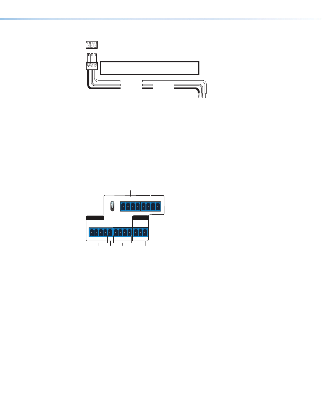
Wiring for RS-232 Control
Use a female 9-pin D-to-bare wire RS-232 cable or a universal control cable (UC50' or
UC100') to connect your computer or control system to the RS-232 pins of the Remote
connector.
1. Wire the unterminated end of the RS-232 cable to the provided 3-pole captive screw
2. Plug the 3-pole connector into the Remote receptacle on the rear panel of the switcher.
3. Connect the other end of the cable to the computer or control system connector.
Figure7 on page13 shows how to wire this shared connector for RS-232.
Smooth
Ridges
A
3/16"
A
12 V
2.2 A MAX
plug as described below. Connect the transmit, receive, and ground wires of the cable
to the first three pins on the connector, starting at the left:
• Connect the transmit wire to pin 1 which plugs into the Tx (transmit) port.
• Connect the receive wire to pin 2 which plugs into the Rx (receive) port.
• Connect the ground wire to pin 3 which plugs into the G (ground) port.
DTP2 T 204 Switcher • Installation 12
m
RS-232 Port
DTP2 T 204 Switcher
RS-232
C+
22
444
333
111
Rear Panel
Tx Rx G
Remote Port
NOTE: If you use cable that has a drain
wire, tie the drain wire to ground at both ends.
Ground (G)
Receive (Rx)
Transmit (Tx)
Transmit (Tx)
Receive (Rx)
Figure 7. Remote Connector Pin Assignments
Wiring the Contact/Tally Connectors
To enable input switching via contact closure, connect a push-button contact closure device
to the C (contact) pin of one of the captive screw contact/tally connectors (see figure3,
, on page 6). To identify the currently selected input when the front panel LEDs are not
F
visible, connect a tally output device, such as an LED, to the T pin of the same contact/tally
connector and a +V pin to power the device if desired. When the input you are using is
selected, the corresponding tally pin shorts to ground, activating the connected indicator.
555 666
POWER
SEND
5
6
Computer or
Control Syste
G
CONT
OFF
12 34
C+VTCTCTCT
REMOTE
RS-232
RxTx
VTGC+VT
G
Figure 8. Contact/tally and Remote RS-232 Ports
The contact/tally section of the rear panel contains four captive screw connectors, each
containing two pairs of pins labeled C and T (see figure 8, 1, 3, 5, and 6). Each C-T pin
pair is labeled with its contact input number (1 through 6), and each individual pin is labeled
with its function:
• C = Contact closure input
• T = Tally output
• G = Ground (for example, 4)
• +V = +V connector for the tally output power wire (for example, 2)
To enable input switching via contact closure, connect a contact closure device to a
contact/tally port as follows:
1. Connect a push-button contact closure device to a C pin of one of the contact/tally
connectors (1, 3, 5, or 6).
2. Connect the ground wire of the contact device to one of the G pins.
3. If desired, to identify the currently selected input when the front panel LEDs are not
visible, connect an indicator device, such as an LED, to tally output pin (T) to the right of
the connected C pin. When the input you are using is selected, the corresponding tally
out pin shorts to ground, which activates the connected indicator.
DTP2 T 204 Switcher • Installation 13
 Loading...