

Page 1

User Guide
DTP2R212 Series
HDMI DTP2 Receiver and Switcher with Audio De-Embedding
DTP Systems
68-2986-01 Rev. B
01 21
Page 2
Safety Instructions
Safety Instructions • English
WARNING: This symbol, , when used on the product, is intended to
alert the user of the presence of uninsulated dangerous voltage within the
product’s enclosure that may present a risk of electric shock.
ATTENTION: This symbol, , when used on the product, is intended
to alert the user of important operating and maintenance (servicing)
instructions in the literature provided with the equipment.
For information on safety guidelines, regulatory compliances, EMI/EMF
compatibility, accessibility, and related topics, see the Extron Safety and
Regulatory Compliance Guide, part number 68-290-01, on the Extron
website, www.extron.com.
Sicherheitsanweisungen • Deutsch
WARNUNG: Dieses Symbol auf dem Produkt soll den Benutzer
darauf aufmerksam machen, dass im Inneren des Gehäuses dieses
Produktes gefährliche Spannungen herrschen, die nicht isoliert sind und
die einen elektrischen Schlag verursachen können.
VORSICHT: Dieses Symbol auf dem Produkt soll dem Benutzer in der im
Lieferumfang enthaltenen Dokumentation besonders wichtige Hinweise
zur Bedienung und Wartung (Instandhaltung) geben.
Weitere Informationen über die Sicherheitsrichtlinien, Produkthandhabung,
EMI/EMF-Kompatibilität, Zugänglichkeit und verwandte Themen finden Sie in
den Extron-Richtlinien für Sicherheit und Handhabung (Artikelnummer
68-290-01) auf der Extron-Website, www.extron.com.
Istruzioni di sicurezza • Italiano
AVVERTENZA: Il simbolo, , se usato sul prodotto, serve ad
avvertire l’utente della presenza di tensione non isolata pericolosa
all’interno del contenitore del prodotto che può costituire un rischio di
scosse elettriche.
ATTENTZIONE: Il simbolo, , se usato sul prodotto, serve ad avvertire
l’utente della presenza di importanti istruzioni di funzionamento e
manutenzione nella documentazione fornita con l’apparecchio.
Per informazioni su parametri di sicurezza, conformità alle normative,
compatibilità EMI/EMF, accessibilità e argomenti simili, fare riferimento
alla Guida alla conformità normativa e di sicurezza di Extron, cod. articolo
68-290-01, sul sito web di Extron, www.extron.com.
I
Instrucciones de seguridad • Español
ADVERTENCIA: Este símbolo, , cuando se utiliza en el producto,
avisa al usuario de la presencia de voltaje peligroso sin aislar dentro del
producto, lo que puede representar un riesgo de descarga eléctrica.
ATENCIÓN: Este símbolo, , cuando se utiliza en el producto,
avisa al usuario de la presencia de importantes instrucciones de uso y
mantenimiento recogidas en la documentación proporcionada con el
equipo.
Para obtener información sobre directrices de seguridad, cumplimiento
de normativas, compatibilidad electromagnética, accesibilidad y temas
relacionados, consulte la Guía de cumplimiento de normativas y seguridad
de Extron, referencia 68-290-01, en el sitio Web de Extron, www.extron.com.
Instructions de sécurité • Français
AVERTISSEMENT : Ce pictogramme, , lorsqu’il est utilisé sur le
produit, signale à l’utilisateur la présence à l’intérieur du boîtier du
produit d’une tension électrique dangereuse susceptible de provoquer
un choc électrique.
ATTENTION : Ce pictogramme, , lorsqu’il est utilisé sur le produit,
signale à l’utilisateur des instructions d’utilisation ou de maintenance
importantes qui se trouvent dans la documentation fournie avec le
matériel.
Pour en savoir plus sur les règles de sécurité, la conformité à la
réglementation, la compatibilité EMI/EMF, l’accessibilité, et autres sujets
connexes, lisez les informations de sécurité et de conformité Extron, réf.
68-290-01, sur le site Extron, www.extron.com.
Page 3
Copyright
© 2020 – 2021 Extron. All rights reserved.
Trademarks
All trademarks mentioned in this guide are the properties of their respective owners.
The following registered trademarks(
®
), registered service marks(
(see the current list of trademarks on the Terms of Use page at www.extron.com):
Extron, Cable Cubby, ControlScript, CrossPoint, DTP, eBUS, EDID Manager, EDID Minder, Flat Field, FlexOS, Glitch Free, Global
Configurator, GlobalScripter, GlobalViewer, Hideaway, HyperLane, IPIntercom, IPLink, KeyMinder, LinkLicense, LockIt, MediaLink,
MediaPort, NAV, NetPA, PlenumVault, PoleVault, PowerCage, PURE3, Quantum, Show Me, SoundField, SpeedMount, SpeedSwitch,
StudioStation, SystemINTEGRATOR, TeamWork, TouchLink, V-Lock, VideoLounge, VN-Matrix, VoiceLift, WallVault, WindoWall, XTP,
XTPSystems, and ZipClip
Registered Service Mark
(SM)
: S3 Service Support Solutions
AAP, AFL (Accu-RATEFrameLock), ADSP(Advanced Digital Sync Processing), AVEdge, CableCover, CDRS(ClassD Ripple Suppression),
Codec Connect, DDSP(Digital Display Sync Processing), DMI (DynamicMotionInterpolation), DriverConfigurator, DSPConfigurator,
DSVP(Digital Sync Validation Processing), eLink, EQIP, Everlast, FastBite, Flex55, FOX, FOXBOX, IP Intercom HelpDesk, MAAP,
MicroDigital, Opti-Torque, PendantConnect, ProDSP, QS-FPC(QuickSwitch Front Panel Controller), RoomAgent, Scope-Trigger,
ShareLink, SIS, SimpleInstructionSet, Skew-Free, SpeedNav, Triple-Action Switching, True4K, Vector™ 4K , WebShare, XTRA, and
ZipCaddy
SM
), and trademarks(TM) are the property of RGBSystems, Inc. or Extron
Registered Trademarks (
Trademarks (™
)
®
)
Page 4

FCC Class A Notice
This equipment has been tested and found to comply with the limits for a Class A digital device,
pursuant to part15 of the FCC rules. The ClassA limits provide reasonable protection against harmful
interference when the equipment is operated in a commercial environment. This equipment generates,
uses, and can radiate radio frequency energy and, if not installed and used in accordance with the
instruction manual, may cause harmful interference to radio communications. Operation of this
equipment in a residential area is likely to cause interference. This interference must be corrected at
the expense of the user.
ATTENTION:
• The Twisted Pair Extension technology works with unshielded twisted pair (UTP)
or shielded twisted pair (STP) cables; but to ensure FCC Class A and CE
compliance, STP cables and STP Connectors are required.
• La technologie extension paires torsadées fonctionne avec les câbles paires
torsadées blindées(UTP) ou non blindées(STP). Afin de s’assurer de la
compatibilité entre FCC ClasseA et CE, les câbles STP et les connecteurs STP
sont nécessaires.
NOTES:
• This unit was tested with shielded I/O cables on the peripheral devices. Shielded
cables must be used to ensure compliance with FCC emissions limits.
• For more information on safety guidelines, regulatory compliances, EMI/EMF
compatibility, accessibility, and related topics, see the Extron Safety and
Regulatory Compliance Guide on the Extron website.
Page 5
Conventions Used in this Guide
Notifications
The following notifications are used in this guide:
WARNING: Potential risk of severe injury or death.
AVERTISSEMENT : Risque potentiel de blessure grave ou de mort.
CAUTION: Risk of minor personal injury.
ATTENTION : Risque de blessuremineure.
ATTENTION:
• Risk of property damage.
• Risque de dommages matériels.
NOTE: A note draws attention to important information.
TIP: A tip provides a suggestion to make working with the application easier.
Software Commands
Commands are written in the fonts shown here:
^AR Merge Scene,,0p1 scene 1,1 ^B 51 ^W^C.0
[01] R 0004 00300 00400 00800 00600 [02] 35 [17] [03]
E X! *X1&* X2)* X2#* X2! CE}
NOTE: For commands and examples of computer or device responses mentioned
in this guide, the character “0” is used for the number zero and “O” is the capital
Computer responses and directory paths that do not have variables are written in the font
shown here:
Variables are written in slanted form as shown here:
Selectable items, such as menu names, menu options, buttons, tabs, and field names are
written in the font shown here:
letter “o.”
Reply from 208.132.180.48: bytes=32 times=2ms TTL=32
C:\Program Files\Extron
ping xxx.xxx.xxx.xxx —t
SOH R Data STX Command ETB ETX
From the File menu, select New.
Click the OK button.
Specifications Availability
Product specifications are available on the Extron website, www.extron.com.
Extron Glossary of Terms
A glossary of terms is available at http://www.extron.com/technology/glossary.aspx.
Page 6

Page 7

Contents
Introduction ................................................1
About this Guide .................................................. 1
About the DTP2R212 ........................................ 1
Features ............................................................. 2
Application Diagrams ........................................... 5
Installation .................................................. 7
Installation Overview ............................................ 7
Rear Panel Features ............................................ 8
Wiring Connections ........................................... 12
Power Connector .......................................... 12
LAN Connector Wiring ................................... 14
TP Connector and
Cable Recommendations ............................. 14
Analog Audio Output Connector .................... 15
Display and Remote RS‑232 Control ............. 16
Remote Control (SA models only) .................. 16
Over DTP2 RS‑232 and IR Control ................ 17
LockIt Lacing Brackets ...................................... 18
Operation.................................................. 19
Front Panel Features .......................................... 19
Operations......................................................... 20
Powering on the Receiver .............................. 20
Selecting an Input .......................................... 20
Front Panel Lockout (Executive Mode) ........... 21
Connecting to the USB Port .............................. 21
Configuration ..................................................... 23
Enabling Auto‑Input Switching ....................... 23
EDID Minder .................................................. 23
HDCP ............................................................ 24
Audio Configuration ....................................... 24
Configuration Software .............................25
Software Installation........................................... 25
Connecting to PCS ............................................ 26
Opening PCS ................................................ 26
Software Overview ............................................. 27
PCS Device Menu ......................................... 27
Software Menu .............................................. 28
Updating Firmware ............................................ 31
Downloading DTP2R212 Firmware .............. 31
Uploading Firmware to the Switcher .............. 32
SIS Commands ......................................... 35
Using Simple Instruction Set (SIS) Commands ... 35
Host‑to‑switcher Communications ................ 35
Switcher‑initiated Messages .......................... 35
Password Messages ..................................... 36
Error Responses ............................................ 36
Timeout ......................................................... 37
Unsolicited Responses .................................. 37
Using the Command and Response Table ..... 37
Symbol Definitions ............................................. 38
Command and Response Table for SIS
Commands ..................................................... 42
Command and Response Table for CEC
Communications SIS Commands .................... 51
Internal Web Page ..................................... 54
Accessing the Internal Web Page ...................... 54
Disabling Compatibility Mode ......................... 55
Web Page Panels .............................................. 55
Device Info Panel ........................................... 56
Device Status Panel ....................................... 56
Network Settings Panel ................................. 57
Firmware Panel .............................................. 58
Roles and Permissions Panel ......................... 59
viiDTP2 R 212 Series • Contents
Page 8

Mounting .................................................. 60
Mounting the DTP2R212 ................................. 60
Tabletop Use ................................................. 60
Rack Mounting .............................................. 60
Furniture Mounting......................................... 60
DTP2 R 212 Series • Contents viii
Page 9

Introduction
This section gives an overview of the Extron DTP2R 212 and DTP2 R 212 SA switching
receivers. Topics include:
• About this Guide
• About the DTP2R212
• Features
• Application Diagrams
About this Guide
This guide describes the DTP2R212 and DTP2R212 SA two‑input switching receivers
and provides instructions on how to install, configure, and operate them. The DTP2R212
switches and extends signals up to 330 feet (100 meters).
Details regarding configurating and operating the receivers through the Extron Product
Configuration Software (PCS) can be found in the DTP2R212 PCS Help File available after
you’ve opened up PCS (see PCS Device Menu on page27).
In this guide, the DTP2R212 and DTP2R212 SA are commonly referred to as “receiver”,
“switcher”, “switching receiver”, or simply as DTP2R212.
About the DTP2R212
The Extron DTP2R212 is a two‑input switcher for 4K video signals with two simultaneous
outputs. The switching receiver features one HDMI and one DTP2 input, and one local
HDMI output. The device also features EDID Minder for managing EDID, and Key Minder for
managing HDCP outputs.
The DTP2R212 can also extract embedded HDMI two‑channel PCM audio to a stereo
captive screw output or an optional stereo amplifier output (DTP2 R 212 SA).
• The DTP2R212 receives the digital signal from Legacy DTP inputs up to 330feet
(100meters) with a maximum resolution of up to 4K @ 60 Hz, 4:2:0, with HDCP1.4,
supporting data rates up to 10.2Gbps.
• The DTP2R212 receives the digital signal from DTP2 inputs up to 330feet
(100meters) with a maximum resolution of up to 4K @ 60 Hz, 4:4:4, with HDCP2.3,
supporting data rates up to 18Gbps.
The switcher is housed in a one‑inch high, three‑quarter rack wide, rack‑mountable metal
enclosure, and is powered by an external power supply.
DTP2 R 212 Series • Introduction 1
Page 10

Features
• Receives HDMI plus control and analog audio up to 330 feet (100 meters)
over a shielded CATx cable — The DTP2 R 212 models provide high reliability and
maximum performance on an economical and easily installed cable infrastructure.
• HDMI and DTP2 inputs
• HDMI input is ideal for connecting to a local source, such as a laptop or
ShareLink wireless collaboration gateway
• Supports computer and video resolutions up to 4K/60 @ 4:4:4 — Support of
4K/60 at 4:4:4 chroma sampling requires connection to a matching DTP2 product.
• Auto-switching between inputs — Auto‑switching allows for simple, unmanaged
installation. When multiple inputs are active, the switching priority is configurable.
• Supported HDMI 2.0b specification features include data rates up to 18 Gbps,
HDR, Deep Color up to 12-bit, 3D, HD lossless audio formats, and CEC
• Support for HDR – High Dynamic Range video — Enables greater contrast range
and wider color gamut by providing the necessary video bandwidth, color depth, and
metadata interchange capability for HDR video.
• HDCP 2.3 compliant — Ensures display of content‑protected 4K video media and
maintains interoperability with earlier versions of HDCP.
• Stereo audio de-embedding — Embedded HDMI two‑channel PCM audio can be
extracted to the stereo captive screw output or the optional stereo amplifier output.
• DTP2 R 212 SA model features energy efficient class D stereo amplifier
• 90 dB signal-to-noise ratio with 0.1% THD+N — Ensures quiet, low‑noise
amplification and maintains audio signal integrity for exceptional performance in a
compact, economical amplifier.
• Extron-patented CDRS™ - Class D Ripple Suppression — CDRS is an
Extron Patented technology that provides a smooth, clean audio waveform and an
improvement in signal fidelity over conventional Class D amplifier designs. CDRS
eliminates the high frequency switching ripple characteristic of Class D amplifiers,
a source of RF emissions which can interfere with sensitive AV equipment such as
wireless microphones.
• Automatic clip limiter — Detects actual onset of clipping by comparing input and
output waveforms. Gain is automatically reduced without audible artifacts to protect
speakers from clipping distortion.
• Selectable volume control — Allows the output volume to be remotely controlled
via SIS or using an optional Extron VCM 110 or VCM 200 analog volume and mute
controller or the VC 50 analog volume controller.
• 25.8 watts rms output power: 2 x 12.9 watts @ 4 ohms or 2 x 7.6 watts
@ 8 ohms — Used in combination with surface mount or ceiling speakers, the
integrated amplifier provides a compact, economical audio solution for classrooms,
meeting rooms and other applications, providing a significant step‑up in sound
quality over the speakers built into displays.
• CEC - Consumer Electronics Control Capability — Standard, built‑in CEC
commands can be triggered to control displays or other AV devices connected to
the HDMI output. The ability to control specific functions, such as power on/off, input
selection, or volume level, is dependent on implementation by the device manufacturer.
• Extron XTP DTP 24 shielded twisted pair cable is strongly recommended for
optimal performance
DTP2 R 212 Series • Introduction 2
Page 11

• Compatible with CATx shielded twisted pair cable — The DTP2R212 models fully
support a maximum transmission distance of 330 feet (100 meters) for all compatible
resolutions when used with CATx shielded twisted pair cable. Shielded twisted pair
cabling with solid center conductor sizes of 24 AWG or better is recommended for
optimal performance.
• Remote power capability with DTP2 products — For simplified installation, the
standard DTP2 R 212 without amplifier can be remotely powered by a DTP2 transmitter
over the twisted pair connection. It can also be configured to provide power to the
connected DTP2 transmitter.
• Accepts additional analog stereo audio signals — The DTP2R212 models accept
stereo analog audio from a DTP‑enabled product. This audio may be switched to the
stereo captive screw output or the optional stereo amplifier output, independent of the
video input selection.
• Stereo audio embedding — Pass‑through audio from the DTP input can be
embedded onto the HDMI output.
• Bidirectional RS-232 and IR pass-through for AV device control — Bidirectional
RS‑232 control and IR signals can be transmitted alongside the video signal, allowing
remote AV devices to be controlled without the need for additional cabling.
• RS-232 insertion from the Ethernet control port — Saves system resources and
simplifies installation by enabling a control processor to access remote RS‑232 devices
over Ethernet.
• Display control RS-232 port — Serial commands inserted from Ethernet can be
routed to this port to control a connected display or other device.
• Supports multiple embedded audio formats — The DTP2R212 models are
compatible with a broad range of multi‑channel audio signals, providing reliable
operation with HDMI sources.
• Compatible with all DTP transmitters and DTP-enabled products — Enables
mixing and matching with desktop and wallplate transmitters, as well as other DTP‑
enabled products to meet application requirements.
• User-selectable HDCP authorization — Allows the unit to appear HDCP compliant
or non‑HDCP compliant to the connected source, which is beneficial if the source
automatically encrypts all content when connected to an HDCP‑compliant device.
Protected material is not passed in non‑HDCP mode.
• Comprehensive EDID management — Use PCS software to access EDID Minder for
setting video input EDID, capturing EDID from connected displays, or uploading custom
EDID files. Proper EDID management ensures that sources and displays are easily
integrated into a system resulting in optimized system operation. Freely downloadable
EDID Manager 2.0 software is available for advanced EDID editing and creating custom
EDID files.
• EDID Minder automatically manages EDID communication between connected
devices — EDID Minder ensures that the source powers up properly and reliably
outputs content for display.
• HDCP authentication and signal presence confirmation — Provides real‑time
verification of HDCP status for each digital video input and output. This allows for
simple, quick, and easy signal and HDCP verification through front panel LEDs, RS‑232,
USB, or Ethernet, providing valuable feedback to a system operator or helpdesk
support staff.
• HDCP Visual Confirmation — When HDCP‑encrypted content is transmitted to
a non‑HDCP compliant display, a full‑screen green signal is sent to the display for
immediate visual confirmation that protected content cannot be viewed on that display.
DTP2 R 212 Series • Introduction 3
Page 12

• HDMI to DVI Interface Format Correction — Automatically enables or disables
embedded audio and InfoFrames, and sets the correct color space for proper
connection to HDMI and DVI displays.
• Automatic color bit depth management — Automatically adjusts color bit depth
based on the display EDID, preventing color compatibility conflicts between source and
displays.
• Output muting control — Provides the capability to mute the HDMI and/or analog
audio output at any time.
• Bass and treble controls
• Selectable stereo or dual mono audio — Allows the user to choose between
stereo output, or to sum the left and right channels into dual mono outputs using SIS
command.
• Ethernet monitoring and control — Enables control and proactive monitoring over a
LAN, WAN, or the Internet.
• Built-in Web pages — Enables the use of a standard browser for device monitoring
and troubleshooting over an intuitive Web interface.
• Front panel security lockout — This feature locks out all front panel functions; all
functions however, are available through USB or RS‑232 control.
• RS-232 control port — Enables the use of serial commands for integration into
a control system. Extron products use the SIS ‑ Simple Instruction Set command
protocol, a set of basic ASCII commands that allow for quick and easy programming.
• Front panel USB configuration port — Provides convenient access for information
and firmware updates.
• LED indicators for signal presence, power, and link status — Provide visual
indication of system status for real‑time feedback and monitoring of key performance
parameters.
• RJ-45 signal and link LED indicators for DTP port — Provide a means for validating
signal flow and operation, allowing quick identification of connectivity issues.
• Easy setup and commissioning with Extron PCS - Product Configuration
Software — Conveniently configure multiple products using a single software
application.
• 1” (2.5 cm) high, three-quarter rack width metal enclosure — With a low profile
enclosure, the device can be installed discreetly wherever needed.
• Includes LockIt HDMI cable lacing brackets
• External Extron Everlast power supply included — Provides worldwide power
compatibility with high‑demonstrated reliability and low power consumption.
• Extron Everlast Power Supply is covered by a 7-year parts and labor warranty
DTP2 R 212 Series • Introduction 4
Page 13
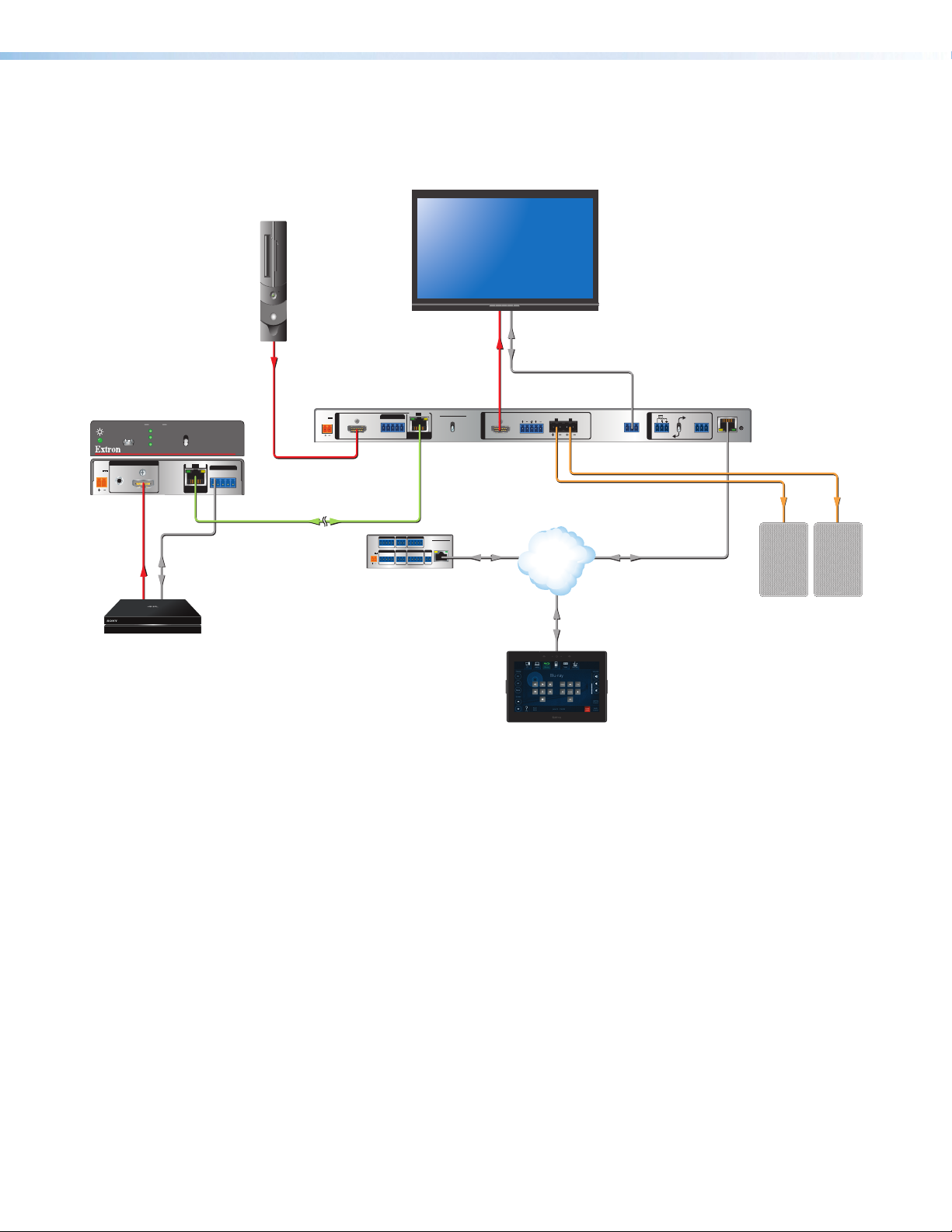
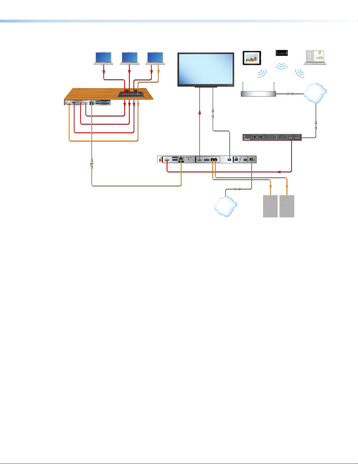
Application Diagrams
The following diagrams show typical applications for the DTP2R212 series.
Extron
DTP2 T 211
Transmitter
POWER
12V
--A MAX
STATUS
CONFIG
INPUTS
AUDIO
HDMI
4K Media Player
INPUT
LINK
OUTPUT
SEND
POWER
OFF
SIG LINK
DTP2 OUT
RS-232
OVER DTP2
RS-232
TxRx Tx RxG
DTP2 T 211
IR
PC with
4K HDR
Video Output
HDMI
Extron
DTP2 R 212 SA
Receiver
POWER
12V
3.0 A MAX
1
INPUTS
HDMI HDMI
CATx Cable
up to 330' (100 m)
4K HDR Display
SIG LINK
OVER DTP2
2
RS-232IR
Rx GTx
COM 1
G
Tx Rx RTSCTS
POWER
VOL
12V
VCG
1A MAX
DTP2 R 212 SA
SEND POWER
RxTx
COM 2
Tx Rx
RELAYS
12C
OFF
DTP2 IN
DIGITAL I/O
IPCPPRO250
G
1 2 3 4G
eBUS
IR/S
+V+S-SG
SG
PWR OUT =6W
LAN
Extron
IPCP Pro 250
IP Link Pro
Control Processor
HDMI
OUTPUT
RS-232
LR
LAN
CLASS 2
4/8 OHM
WIRING
L
R
DISPLAY
RS-232
VOL
10V50mA
RS-232
REMOTE
Rx GTx
CVG
R
RxTx G
LAN
Audio
Extron
Extron
Extron
SM 3
Surface Mount
TLP Pro 725M
7" Wall Mount
Touchlink Pro
Touchpanel
Speakers
Figure 1. Typical Switching Receiver Application
DTP2 R 212 Series • Introduction 5
Page 14
Extron
DTP T DSW
4K 233
Transmitter
Laptop
Laptop Laptop
Flat Panel Display
MODEL 80
Smartphone
AudioVGAHDMIDisplayPort
FLAT PANEL
Extron
POWER
1
23
12V
AUDIO
--A MAX
RGB
HDMI DP
INPUTS
REMOTE
SIG
LINK
OVER DTP
HDBT
RS-232
CONTACT IN
TALLY OUT
IR
RS-232
RxTx
123G123+V
RxGTx RxTxG
DTP
OUT
DisplayPort
HDMI
Cable Cubby
Extron
Cable Cubby 700
Series/2 Cable
Access Enclosure
HDMI
RS-232
VGA
Audio
Extron
Tablet
Wireless
Facility/Room
Wireless Access Point
Extron
ShareLink Pro 1000
Collaboration Gateway
CONFIG
HDMI
HDMI
WINDOW
PASS-THROUGH
SIGNAL
HDCP
HDMI DECODER
OUTPUTINPUT
HD WIN
STANDBY
SCREEN
Ethernet
USB
12
HD PASS
DECODER
ShareLink Pro 1000
Laptop
LAN
Ethernet
DTP2 R 212 SA
CATx Cable
up to 230'
(70 m)
Receiver
POWER
12V
3.0 A MAX
SIGLINK
DTP2 R 212 SA
OVER DTP2
INPUTS
SEND POWER
2
RS-232 IR
AUTO
1
INPUTS
HDMI HDMI
1
SWITCH
CONFIG
OFF
MODE NORM/AUTO
RxTx
RxGTx
DTP2 IN
CLASS 2
4/8 OHM
LR
2
OUTPUT
WIRING
L
R
VOL
10V 50mA
DISPLAY
OUTPUT
INPUTS
RS-232
RS-232
12
SIGNAL
HDCP
REMOTE
RxGTx
CVG
RxTx G
DTP2 R 212 SERIES
R
LAN
HDMI
Audio
Ethernet
LAN
Extron Extron
Extron
SM 3
Surface Mount
Speakers
Figure 2. Typical Switching Receiver Application
DTP2 R 212 Series • Introduction 6
Page 15

Installation
This section describes the installation and setup of the DTP2R212 switcher. Topics include:
• Installation Overview
• Rear Panel Features
• Wiring Connections
• LockIt Lacing Brackets
Installation Overview
To install and set up the DTP2R212 switching receiver:
1. Turn off all equipment and disconnect it from the power source.
2. Mount the switcher (optional) on a rack shelf or furniture (see Mounting the
DTP2R212 on page60).
3. Connect an HDMI input source to the DTP2R212 input. The default (Extron) EDID is
present and Hot Plug Detect (HPD) is actively controlled on the input.
NOTE: LockIt cable lacing brackets are provided to secure the HDMI cables to the
rear panel ports to reduce stress on the HDMI connectors and prevent signal loss
due to loose cable connections (see the LockIt Lacing Brackets on page18).
4. Connect an HDMI output device to the HDMI output. By default, the EDID of this
device is stored at the HDMI inputs.
5. Connect an RJ-45 DTP2 transmitting device to the DTP2 In connector (see
figure3, D, on page8), set the Send Power switch (E).
ATTENTION:
• Position this switch (see figure3, E) BEFORE connecting the appropriate
device to the TP connector. Failure to comply can damage the endpoint.
• Positionnez le sélecteur (voir figure3, E) AVANT de connecter l’appareil
approprié au connecteur TP. Ne pas respecter cette procédure pourrait
endommager le point de connexion.
• If the transmitting device is in the Extron DTP2 series and you are setting up the
DTP2R212 receiver to supply power to the transmitter:
• Set the receiver SEND POWER switch (E) to the “UP” (SEND POWER)
position (see figure4 on page10).
• Set the transmitter SEND POWER switch (E) to the “DOWN” (OFF) position.
• If the transmitting device is in the Extron DTP2 series and you setting up the
DTP2R212 (non‑amplifier model) to receive power from the transmitter:
• Set the receiver SEND POWER switch of the receiver (E) to the “DOWN”
(OFF) position (see figure4 on page10).
• Set the transmitter SEND POWER switch to the “UP” (SEND POWER)
position.
DTP2 R 212 Series • Installation 7
Page 16
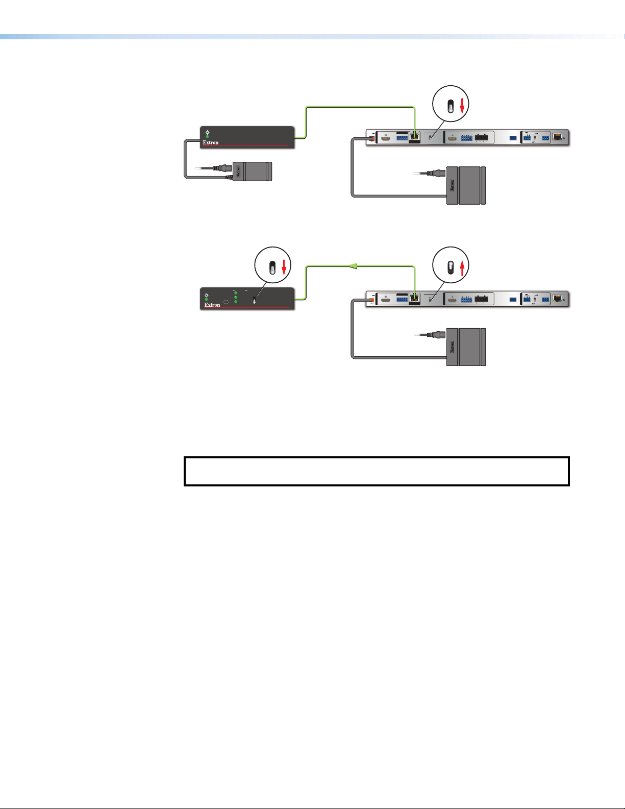
• If the transmitting device is in the Extron DTP2 series and you setting up the
**
DTP2R212 SA (amplifier model), you can only set the receiver to send power to
the transmitter:
• Set the receiver SEND POWER switch of the receiver (E) to the “UP” (SEND
POWER) position (see figure5 on page11).
• Set the transmitter SEND POWER switch of the transmitter to the “DOWN”
(OFF) position.
• If the transmitting device is in the Extron Legacy DTP series and not the DTP2
series, set the SEND POWER switches of both devices to the “DOWN” (OFF)
position (see figure4 on page10).
6. Connect Over DTP RS-232 and IR control. Connect a serial RS‑232 signal, a
modulated IR signal, or both into this 3.5mm, 5‑pole captive screw port (C) for
bidirectional RS‑232 and IR communication (see Over DTP2 RS-232 and IR Control
on page17 for connection procedures).
7. Connect control devices. Connect your computer to one of the following ports to
configure and control the device via SIS commands or PCS:
• RS-232 port — This 3‑pole RS‑232 port (L) for serial RS‑232 control (see
Display and Remote RS-232 Control on page16 for connection procedures).
• Config port — USB mini‑B port for USB control (see Connecting to the USB
Port on page21 for connection procedures).
• LAN (Ethernet) port — Connect an Ethernet cable for LAN control. LEDs on
the connector indicate link and activity status (see LAN Connector Wiring on
page14 for connection wiring).
8. Power on the output display.
9. Connect power to the switcher (see Powering on the Receiver on page20).
10. (Optional) Configure EDID Minder (see the DTP2R212 PCS Help File).
11. Power on the source devices.
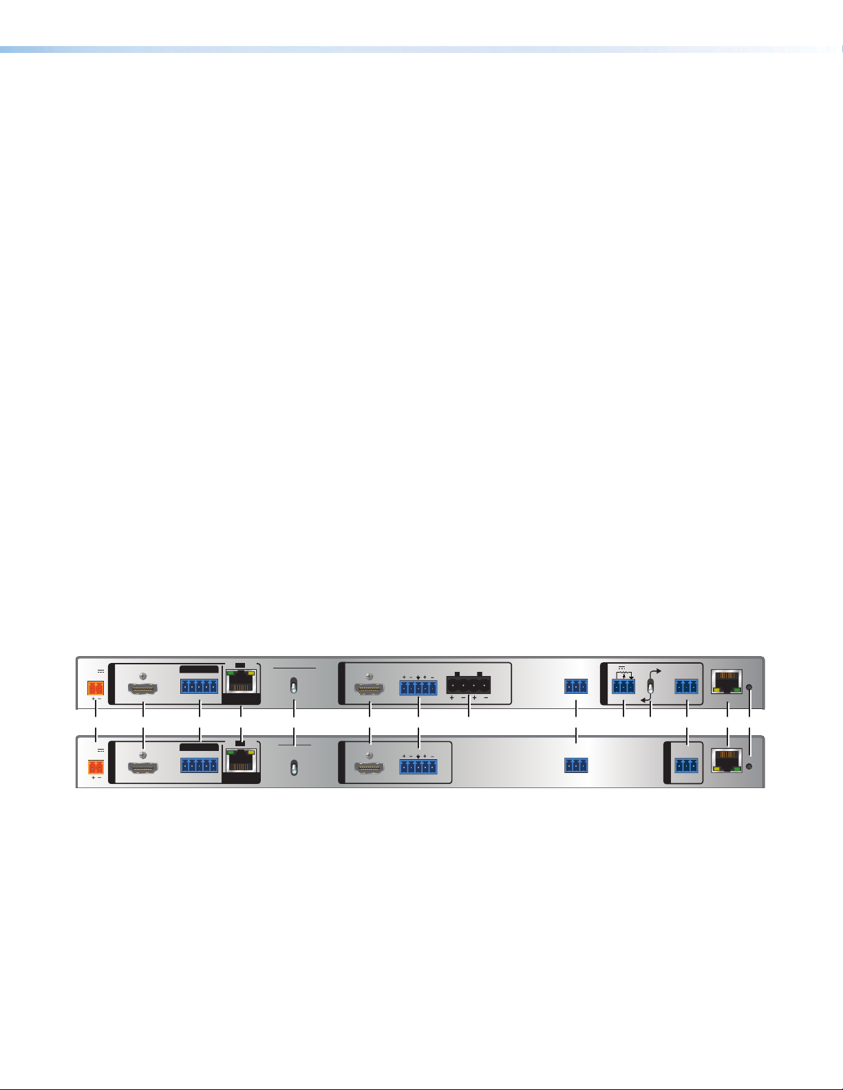
Rear Panel Features
POWER
12V
3.0 A MAX
POWER
12V
2.0 A MAX
1
INPUTS
HDMI HDMI
B DCA I J LKGF H M NE
1
INPUTS
HDMI HDMI
OVER DTP2
2
RS-232 IR
OVER DTP2
RS-232
2
Rx GTx
Rx GTx
IR
RxTx
RxTx
SIGLINK
DTP2 IN
SIGLINK
DTP2 IN
A
B
C
D
E
F
G
DTP2 R 212 SA
SEND POWER
OFF
DTP2 R 212
SEND
POWER
OFF
OUTPUT
OUTPUT
Power inlet
HDMI input
OVER DTP2 control
DTP2 IN RJ-45 port
Send Power toggle switch
HDMI output
Audio output
Figure 3. Rear Panel Features
LR
4/8 OHM
CLASS 2
WIRING
L
R
DISPLAY
RS-232
Rx GTx
10V 50mA
REMOTE
CVG
VOL
RS-232
RxTx G
*
LR
Amplified audio output (SA models)
H
Display control
I
Remote amplified volume control
J
DISPLAY
RS-232
Rx GTx
RS-232
REMOTE
RxTx G
(SA models)
Switch for volume control
K
(SA models)
Remote RS-232 port
L
LAN (Ethernet) port
M
Reset button
N
DTP2 R 212 Series • Installation 8
R
LAN
R
LAN
Page 17

Power inlet — Plug the provided external 12VDC power supply into this 2‑pole,
A
3.5mm captive screw inlet and into an DC power outlet (see Power Connector on
page12).
NOTE: The DTP2 R 212 SA model is supplied with, and requires, a higher‑wattage
power supply (4.2 A, 50 Watts). The non‑SA model can use a standard 2.0 A,
24Watt supply.
HDMI input — Connect a HDMI video source to this female type A HDMI connector.
B
This port can also accept DVI video with appropriate adapter.
NOTE: LockIt cable lacing brackets are provided to secure the HDMI cables to the
rear panel ports and reduce stress on the connectors, preventing signal loss due
to loose cable connections (see LockIt Lacing Brackets on page18).
OVER DTP2 control — Connect a serial RS‑232 signal, a modulated IR signal,
C
or both into this 3.5mm, 5‑pole captive screw port for bidirectional RS‑232 and IR
communication (see Over DTP2 RS-232 and IR Control on page17 to wire the
connector).
DTP2 IN RJ-45 port — Plug one end of a DTP2 cable to this RJ‑45 female port.
D
Plug the opposite end of this cable into the DTP port on a compatible transmitter (see
TP Connector and Cable Recommendations on page14 to wire the RJ‑45
connector and NOTES on page15).
• Signal LED — Lights green when the unit is sensing a TMDS clock signal on the
DTP2 input.
• Link LED — Lights amber to indicate a valid link is established between the units.
ATTENTION:
• Do not connect this device to a telecommunications or computer data network.
• Ne connectez pas cet appareil à un réseau de télécommunications ou de
données informatiques.
Send Power toggle switch (see figure3 on page8) — The Send Power switch
E
enables or disables the sending of power from the receiver to a DTP2 transmitter.
Set the toggle switch to the UP (Send Power) position on the powered DTP2 unit to
enable sending remote power to the other device. Set the toggle switch to the DOWN
(OFF) position on the DTP2 unit receiving power.
NOTES: Guidelines for setting the Send Power switch:
• If you are using the DTP2 R 212 SA (amplified audio) receiver, the power output
of the DTP2 transmitter is not enough to power the receiver. You can send
power from the receiver to the transmitter, but not from the transmitter to the
receiver (see figure5 on page11).
• If you are using the DTP2 R 212 receiver (not the SA model), the power output
of the DTP2 transmitter is enough to power the receiver. You can send power
either way, if desired (see figure4 on page10).
DTP2 R 212 Series • Installation 9
Page 18
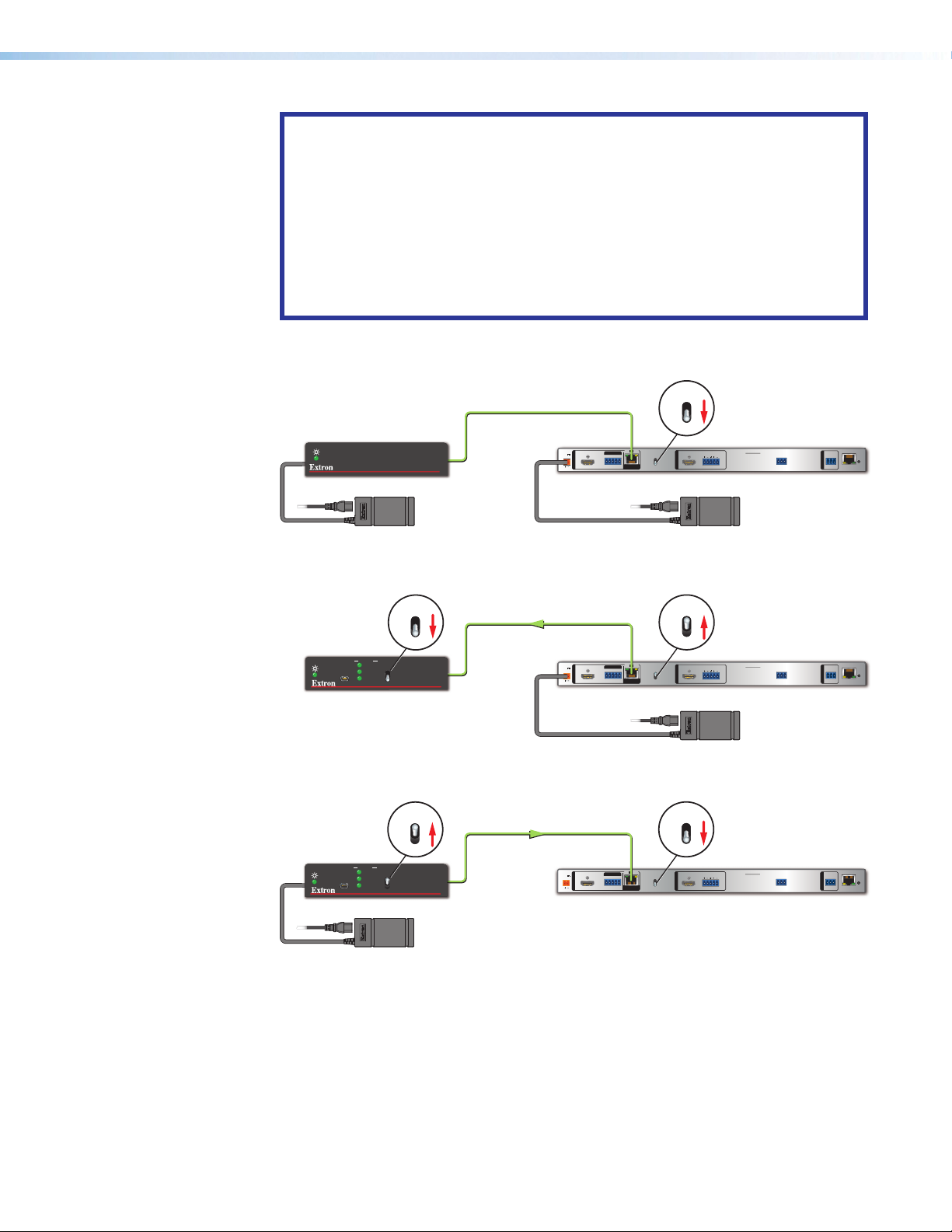
ATTENTION:
• The DTP2R212 device is configured to send or receive power with other
DTP2 models only. If connected to a Legacy DTP device, set the SEND
POWER toggle switch to the “DOWN” position (OFF). Failure to turn the power
OFF will damage the connected DTP device (see figure4).
• Le DTP2R212 est configuré pour fournir une alimentation aux modèles
DTP2 uniquement. S’il est connecté à un autre appareil, veuillez positionner
l’interrupteur à bascule sur « DOWN » (OFF). Si l’interrupteur n’est pas
positionné sur OFF, vous risquez d’entraîner la défaillance de l’appareil Legacy
DTP connecté (voir figure4).
OFF
SEND
Extron
DTP HDMI 4K 330 Tx
Transmitter
STATUS
INPUT
LINK
CONFIG
OUTPUT
Power Supply
SEND
POWER
Local
DTP HDMI 330 Tx
OFF
DTP2 T 211
No Remote Power
CATx Cable
up to 330' (100 m)
POWER
12V
2.0 A MAX
Extron
DTP2 R 212
Receiver
SIG LINK
OVER DTP2
2
IR
RS-232
1
INPUTS
Rx GTx
RxTx
HDMI HDMI
DTP2 IN
POWER
OFF
SEND
POWER
OUTPUT
OFF
LR
DTP2 R 212
Extron
PS 1220
(2 A, 24 Watts)
DISPLAY
RS-232
RS-232
R
REMOTE
Rx GTx
RxTx G
LAN
OFF
Direction of
Remote Power
CATx Cable
up to 330' (100 m)
POWER
12V
2.0 A MAX
Extron
DTP2 R 212
Receiver
SIG LINK
OVER DTP2
IR
RS-232
2
1
INPUTS
RxTx
Rx GTx
HDMI HDMI
DTP2 IN
Extron
DTP2 T 211
Transmitter
CONFIG
STATUS
INPUT
LINK
OUTPUT
SEND
POWER
SEND
POWER
OFF
OFF
DTP2 T 211
ON
Extron
DTP2 T 211
Transmitter
CONFIG
Power Supply
STATUS
INPUT
LINK
OUTPUT
SEND
POWER
Local
SEND
POWER
OFF
OFF
DTP2 T 211
Direction of
Remote Power
CATx Cable
up to 330' (100 m)
POWER
12V
2.0 A MAX
Extron
DTP2 R 212
Receiver
SIG LINK
OVER DTP2
IR
RS-232
2
1
INPUTS
RxTx
Rx GTx
HDMI HDMI
DTP2 IN
ON
SEND
POWER
OFF
DTP2 R 212
SEND
POWER
OFF
LR
OUTPUT
DISPLAY
RS-232
Rx GTx
Extron
PS 1220
(2 A, 24 Watts)
RS-232
R
REMOTE
RxTx G
LAN
OFF
SEND
POWER
OFF
DTP2 R 212
SEND
POWER
OFF
LR
OUTPUT
DISPLAY
RS-232
RS-232
R
REMOTE
Rx GTx
RxTx G
LAN
Figure 4. DTP2 R 212 (non-SA) Send Power Toggle Switch Configuration
DTP2 R 212 Series • Installation 10
Page 19
Extron
DTP2 Endpoint Connected to a DTP2 Endpoint
DTP HDMI 4K 330 Tx
Transmitter
STATUS
INPUT
LINK
CONFIG
OUTPUT
Power Supply
SEND
POWER
Local
DTP HDMI 330 Tx
OFF
DTP2 T 211
No Remote Power
CATx Cable
up to 330' (100 m)
POWER
12V
3.0 A MAX
Extron
DTP2 R 212 SA
Receiver
INPUTS
HDMI HDMI
OFF
Rx GTx
RxTx
DTP2 IN
SIG LINK
DTP2 R 212 SA
OVER DTP2
SEND POWER
2
RS-232 IR
1
OFF
SEND
POWER
OFF
OUTPUT
LR
CLASS 2
4/8 OHM
WIRING
L
R
Extron
PS 1242
(4.2 A, 50 Watts)
VOL
10V 50mA
DISPLAY
RS-232
RS-232
REMOTE
Rx GTx
CVG
R
RxTx G
LAN
Extron
DTP2 T 211
Transmitter
CONFIG
STATUS
INPUT
LINK
OUTPUT
SEND
POWER
OFF
SEND
POWER
OFF
OFF
DTP2 T 211
Direction of
Remote Power
CATx Cable
up to 330' (100 m)
POWER
12V
3.0 A MAX
Extron
DTP2 R 212 SA
Receiver
SIG LINK
OVER DTP2
2
RS-232 IR
1
INPUTS
RxTx
Rx GTx
HDMI HDMI
DTP2 IN
DTP2 R 212 SA
SEND POWER
ON
SEND
POWER
OFF
CLASS 2
4/8 OHM
LR
OUTPUT
OFF
WIRING
L
R
Extron
PS 1242
(4.2 A, 50 Watts)
VOL
10V50mA
DISPLAY
RS-232
RS-232
REMOTE
Rx GTx
CVG
R
RxTx G
LAN
Figure 5. DTP2 R 212 SA Send Power Toggle Switch Configuration
HDMI output — Connect an HDMI display device to this female Type A HDMI port. The
F
EDID information is read from the connected output device via this port and is written
to memory on each input whenever the output device is connected to this port and
powered on.
NOTE: The EDID information is also read and stored whenever power is recycled to
G
the connected output device or when the output device is replaced.
Audio output — Connect a 5‑pole captive screw connector for balanced or
unbalanced analog audio output. This audio output is not amplified and can be
connected to an external amplifier.
Amplified audio output (SA models only) — Connect a 4‑pole captive screw
H
connector for amplified audio output to external speakers.
Display control — Use 3‑pole captive screw connector for bi‑directional RS‑232
I
control of a connected display device.
Remote amplified volume control port (SA models only) — Connect an external
J
audio controller to control volume and mute levels remotely via this 3.5mm, 3‑pole
captive screw port (see Remote Control (SA models only) on page16 for more
information and to wire the connection).
Switch for volume control (SA models only) — When using the amplified output
K
connector (H), flip the switch to the lower position for remote volume control of the
amplified output through port J.
Remote RS-232 port — Connect a serial RS‑232 device via this 3.5mm, 3‑pole
L
captive screw port for remote control of the DTP2 R 212 (see Display and Remote
RS-232 Control on page16 to wire the connector).
DTP2 R 212 Series • Installation 11
Page 20
LAN (Ethernet) port — Use an RJ‑45 cable to connect this jack to a LAN (Ethernet)
(5 mm) Max.
POWER
M
for control of the device.
Reset button — With a tweeker or other pointed tool, press and hold the recessed
N
reset button:
• Press and hold for 3 seconds to reset back to factory default. IP settings are
• Press and hold for 10 seconds to reset back to factory default. IP settings are reset
• Press and hold while powering the unit on enables the unit to revert to factory
Wiring Connections
Power Connector
A 12VDC power supply is provided with the DTP2R212. Follow these instructions to wire
the 2‑pole captive screw connector to your power supply:
CAUTION: The DC output cables must be kept separate from each other while the
power supply is plugged in. Remove power before wiring.
ATTENTION : Les câbles de sortie CC doivent être séparés les uns des autres tant que
la source d’alimentation est branchée. Coupez l’alimentation avant d’effectuer tout
raccordement.
retained.
to default.
default firmware version and factory default setting.
NOTE: The receiver can also be reset to factory settings using SIS commands (see
Reset on page50) or PCS (see PCS Device Menu on page27).
ATTENTION:
• Do not connect power to the DTP2 R 212 until you have read the ATTENTION
notifications on the next page.
• Ne branchez pas l’alimentation au DTP2 R 212 avant d’avoir lu les mises en garde
« ATTENTION » en page suivante.
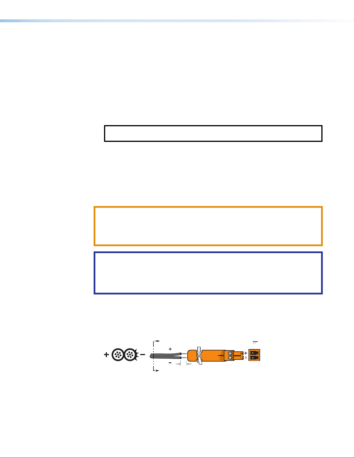
1. Cut the DC output cord to the length needed.
2. Strip the jacket to expose 3/16inch (5mm) of the conductors (see figure6).
3. Slide the leads into the supplied 2‑pole captive screw connector and secure them,
using a small screwdriver.
SECTION A–A
Smooth
Ridges
A
3/16"
A
12V
--A MAX
Figure 6. Wiring the Power Connector
4. To verify the power cord polarity before connecting the plug, connect the power supply
with no load and check the output with a voltmeter.
5. Use the supplied tie wrap to strap the power cord to the extended tail of the connector.
DTP2 R 212 Series • Installation 12
Page 21

ATTENTION:
• Always use a power supply provided by or specified by Extron. Use of an unauthorized
power supply voids all regulatory compliance certification and may cause damage to
the supply and the end product.
• Utilisez toujours une source d’alimentation fournie ou recommandée par Extron.
L’utilisation d’une source d’alimentation non autorisée annule toute certification de
conformité réglementaire, et peut endommager la source d’alimentation et l’unité.
• The installation must always be in accordance with the applicable provisions of National
Electrical Code ANSI/NFPA 70, article 725 and the Canadian Electrical Code part 1,
section 16. The power supply shall not be permanently fixed to building structure or
similar structure.
• Cette installation doit toujours être conforme aux dispositions applicables du Code
américain de l’électricité (National Electrical Code) ANSI/NFPA 70, article 725, et du
Code canadien de l’électricité, partie1, section16. La source d’alimentation ne devra
pas être fixée de façon permanente à la structure de bâtiment ou à d’autres structures
similaires.
• Use a UL Listed external power supply with rated output 12 VDC, minimum 0.3 A, NEC
Class 2, or LPS output.
• Utilisez une source d’alimentation externe certifiée UL, avec une tension nominale 12
Vcc, 0,3 A minmum, NEC Class 2, ou sortie LPS.
• Power supply voltage polarity is critical. Incorrect voltage polarity can damage the
power supply and the unit. The ridges on the side of the cord identify the power cord
negative lead (see figure6 on page12). To verify the polarity before connection,
plug in the power supply with no load and check the output with a voltmeter.
• La polarité de la source d’alimentation est primordiale. Une polarité incorrecte pourrait
endommager la source d’alimentation et l’unité. Les stries sur le côté du cordon
permettent de repérer le pôle négatif du cordon d’alimentation (voir figure6 sur la
page12). Pour vérifier la polarité avant la connexion, brancher l’alimentation hors
charge et mesurer sa sortie avec un voltmètre.
• The length of the exposed wires in the stripping process is important. The ideal length
is 3/16 inches (5 mm). Any longer and the exposed wires may touch, causing a short
circuit between them. Any shorter and the wires can be easily pulled out even if tightly
fastened by the captive screws.
• La longueur des câbles exposés est importante lorsque l’on entreprend de les dénuder.
La longueur idéale est de 5mm (3/16inches). S’ils sont trop longs, les câbles exposés
pourraient se toucher et provoquer un court‑circuit. S’ils sont trop courts, ils peuvent
être tirés facilement, même s’ils sont correctement serrés par les borniers à vis.
• Unless otherwise stated, the AC/DC adapters are not suitable for use in air handling
spaces or in wall cavities.
• Sauf mention contraire, les adaptateurs CA/CC ne conviennent pas à une utilisation
dans les espaces d’aération ou dans les cavités murales.
• Remote power is intended for indoors use only. No part of a network that uses remote
power can be routed outdoors.
• L’alimentation à distance est exclusivement réservée à un usage en intérieur. Un réseau
utilisant une alimentation à distance ne peut pas être routé en extérieur.
• The power supply shall not be permanently fixed to building structure or similar
structure.
• La source d’alimentation ne devra pas être fixée de façon permanente à la structure
de bâtiment ou à d’autres structures similaires.
DTP2 R 212 Series • Installation 13
Page 22

LAN Connector Wiring
Pins:
T568B T568AT568BTIA/EIA-T568B
Side
Pair Wires
Pins:
See figure7 for the LAN (Ethernet) wiring standard. Use this standard to terminate the LAN
cable with a RJ‑45 connector.
• Use a straight‑through cable for connection to a switch, hub, or router.
• Use a crossover cable or a straight‑through cable for connection directly to a PC.
Wire the connector as shown in figure8.
12345678
Crossover Cable
(for direct connection to a PC)
End 1 End 2
Pin Wire Color Pin Wire Color
1 white-orange 1 white-green
2 orange 2 green
3 white-green 3 white-orange
4 blue 4 blue
5 white-blue 5 white-blue
6 green 6 orange
7 white-brown 7 white-brown
8 brown 8 brown
RJ-45
Connector
Insert Twisted
Pair Wires
Straight-through Cable
(for connection to a switch, hub, or router)
End 1 End 2
Pin Wire Color Pin Wire Color
1 white-orange 1 white-orange
2 orange 2 orange
3 white-green 3 white-green
4 blue 4 blue
5 white-blue 5 white-blue
6 green 6 green
7 white-brown 7 white-brown
8 brown 8 brown
Figure 7. LAN Connector Wiring
TP Connector and Cable Recommendations
See figure8 for the TIA/EIAT568B wiring standard. Use this standard to terminate the
DTP2 cable with a RJ‑45 connector.
12345678
Insert
Twisted
RJ-45
Connector
TIA/EIA
T568B
Pin
Wire color
White-orange
1
Orange
2
3
White-green
4
Blue
5
White-blue
6
Green
7
White-brown
8
Brown
Figure 8. TP Cable Termination
ATTENTION:
• Do not use Extron UTP23SF‑4 Enhanced Skew‑Free AV UTP cable or STP201
cable to link the DTP products or with DTP receivers or receivers. The DTP2R212
does not work properly with these cables.
• N’utilisez pas le câble audiovisuel Skew Free UTP version améliorée UTP23SF‑4
Extron ou le câble STP201 pour relier l’émetteur et le récepteur/sélecteur. Le
DTP2R212 ne fonctionne pas correctement avec ces câbles.
Supported cables
The DTP2R212 switcher is compatible with shielded twisted pair (STP) and unshielded
twisted pair (U/UTP) cable. However, Extron strongly recommends that you use STP cable
to achieve best performance.
DTP2 R 212 Series • Installation 14
Page 23

Cable recommendations
Tip
NO GROUND HERE
Tip
LR
Sleeves
Tip
Ring
Tip
Ring
LR
Extron recommends using the following practices to achieve full transmission distances up
to 230feet (70meters) or 330feet (100meters) and reduce transmission errors.
• Use the following Extron XTPDTP24STP cables and DTP 24 connectors for the best
performance:
• XTP DTP 24/1000 Non‑Plenum 1000feet (305meters) spool
• XTP DTP 24P/1000 Plenum 1000feet (305meters) spool
• XTP DTP 24 Plug Package of 10
• If not using XTP DTP 24 cable, at a minimum, Extron recommends 24 AWG, solid
conductor, STP cable with a minimum bandwidth of 400MHz.
• Terminate cables with shielded connectors to the TIA/EIA‑T568B standard.
• Use no more than two pass‑through points, which may include patch points, punch
down connectors, couplers, and power injectors. If these pass‑through points are
required, use Category 6 or 6a shielded couplers and punch down connectors.
NOTE: When using TP cable in bundles or conduits, consider the following:
• Do not exceed 40% fill capacity in conduits.
• Do not comb the cable for the first 20 meters, where cables are straightened,
aligned, and secured in tight bundles.
• Loosely place cables and limit the use of tie wraps or hook‑and‑loop fasteners.
• Separate twisted pair cables from AC power cables.
Analog Audio Output Connector
Analog audio output connector
Connect an audio device, such as an audio amplifier or powered speakers, to a
3.5 millimeter, 5‑pole captive screw connector (see figure9). This connector outputs
unamplified, line level audio. Use the supplied tie‑wrap to strap the audio cable to the
extended tail of the connector.
Tip
Sleeve
Tip
Sleeve
Unbalanced Stereo Input
LR
Sleeves
Ring
Tip
Ring
Balanced Stereo Input
LR
Sleeve
Tip
Unbalanced Mono Input
LR
Sleeve
Tip
Ring
Tip
Figure 9. Captive Screw Connector for Wiring Audio Output
ATTENTION:
• For unbalanced audio, connect the sleeves to the ground contact. DO NOT
connect the sleeves to the negative (‑) contacts.
• Pour l’audio asymétrique, connectez les manchons au contact au sol. NE PAS
connecter les manchons aux contacts négatifs (–).
NOTES:
• The length of exposed wires is important. The ideal length is
3/16 inch (5 millimeter) (see figure at right).
• Do not tin the wires!
Do not tin the wires!
LR
Balanced Mono Input
DTP2 R 212 Series • Installation 15
Page 24

Display and Remote RS‑232 Control
REMOTE
Use a 3‑pole captive screw connector to connect to the Display and Remote RS‑232
ports. Use the Display port for a display device and the Remote port for a computer or
control system.
1. Wire the unterminated end of the RS‑232 cable to the three pins of the 3‑pole
captive screw connector, starting at the left of the 3‑pole captive screw connector
(see figure10):
a. Connect the transmit wire from the RS‑232 device into the Rx pin of the switcher.
b. Connect the receive wire from the RS‑232 device into the Tx pin of the switcher.
c. Connect the ground wire from the RS‑232 device into the G pin of the switcher.
2. Plug the 3‑pole connector into the appropriate Display or Remote port on the rear
panel of the switcher.
3. Connect the other end of the cable to the appropriate computer or control system port.
TransmitReceive
ReceiveTransmit
GroundGround
Figure 10. Remote Control RS-232 Connector
Remote Control (SA models only)
RS-232
Tx Rx G
This 3‑pin, captive screw port allows an external audio controller to control volume and
mute levels remotely. When using the remote for the SA model, be sure to first set the VOL
switch to the lower position (see figure3 on page8).
Wiring for potentiometer volume control
Options for remote volume control include the Extron VC 50, VCM 100 AAP, VCM 100
MAAP, VCM 200 series, and MLA VC10 Plus. Third party 10k potentiometer volume
controllers can also be connected to this port.
Figure 11 and the following instructions show the wiring for the VMS 100 MAAP. Wiring
other remote control connectors is similar.
10V 50mA
REMOTE
VCG
10 V (Pin 1)
Volume Pot
10k ohms
2k ohms
Mute
Switch
Vol/Mute
(Pin 2)
Ground (Pin 3)
Figure 11. Remote Control Wiring (SA models only)
DTP2 R 212 Series • Installation 16
Page 25

• Pin 1 is for 10 VCD reference voltage output (see figure11 on the previous page).
• Pin 2 (C) has two functions:
• Volume control: it can be used as a variable voltage input between 0 and 10 VDC,
with 0 V giving full attenuation and 10 V giving maximum volume.
• Mute: it can be used for remote control muting. Sound is muted while this pin is
shorted to ground.
• Pin 3 is for the ground connection.
NOTE: All nominal levels are at ±10%.
Over DTP2 RS‑232 and IR Control
Use a female 9‑pin D connector to bare wire RS‑232 cable or a universal control cable
(UC50’ or UC100’) to connect your computer or control system to the Over DTP2 RS-232
and IR port (see figure12, to wire this 5‑pole connector).
1. Wire the unterminated end of the RS‑232 cable to the first three pins on the 5‑pole
captive screw connector, starting at the left:
a. Connect the transmit wire from the RS‑232 device into the Rx pin on the switcher.
b. Connect the receive wire from the RS‑232 device into the Tx pin on the switcher.
c. Connect the ground wire from the RS‑232 device into the G pin on the switcher.
2. Wire the unterminated end of the IR cable to the third, fourth, and fifth pins of the
5‑pole captive screw connector:
a. Connect the transmit wire from the IR device into the Rx pin on the switcher.
b. Connect the receive wire from the IR device into the Tx pin on the switcher.
c. Connect the ground wire from the IR device into the G pin on the switcher.
3. Plug the 5‑pole connector into the Over DTP2 port on the rear panel of the switcher.
4. Connect the other end of the cable to the appropriate computer or control system port.
Tx/Rx
Pins
OVER DTP2 RS-232/IR
IR Device
Tx Rx Gnd
IR
Tx Rx Tx RxG
RS-232
OVER DTP2
Tx Rx Gnd
RS-232 Device
Figure 12. OVER DTP2 RS‑232 and IR Control Pin Assignments
NOTES:
• The RS‑232 and IR connectors share the ground pole and the data from both can
be transmitted simultaneously.
• The IR Tx and Rx line pairs and the RS‑232 Tx and Rx line pairs must each cross
once between their connectors and the source or destination.
• The length and preparation of exposed wires is important (see the wiring
ATTENTION: on page12 for details).
DTP2 R 212 Series • Installation 17
Page 26

LockIt Lacing Brackets
2
3
4
5
Use the included LockIt lacing brackets to securely fasten the HDMI cables to each device
as follows.
Plug the HDMI cable into the rear panel connection.
1
Loosen the HDMI connection mounting screw from the
2
panel enough to allow the LockIt lacing bracket to be
placed over it. The screw does not have to be removed.
Place the LockIt lacing bracket on the screw and
3
against the HDMI connector, then tighten the screw to
secure the bracket.
ATTENTION:
• Do not overtighten the HDMI connector mounting
screw. The shield it fastens to is very thin and can
easily be stripped.
• Ne serrez pas trop la vis de montage du
connecteur HDMI. Le blindage auquel elle est
attachée est très fin et peut facilement être
dénudé.
Loosely place the included tie wrap around the HDMI
4
connector and the LockIt lacing bracket as shown.
While holding the connector securely against the lacing bracket, use pliers or similar
5
tools to tighten the tie wrap, then remove any excess length.
111
3
3
4
4
5
5
2
2
3
DTP2 R 212 Series • Installation 18
Page 27

Operation
This section describes the operation of the DTP2R212 switching receiver.
Topics include:
• Front Panel Features
• Operations
• Connecting to the USB Port
• Configuration
Front Panel Features
D E
AUTO
SWITCH
CONFIG
A B C F
INPUTS
1
MODE NORM/AUTO
2
SIGNAL
HDCP
INPUTS
12
OUTPUT
DTP2 R 212 SERIES
Power indicator LED
A
Auto Switch LED
B
USB Config port
C
Input selection buttons and LEDs
D
Signal Status LEDs
E
HDCP Status LEDs
F
Figure 13. Front Panel Features
Power indicator LED — Lights when power is on.
A
Auto Switch LED — Lights when Auto Switch is enabled.
B
USB Configuration port — Connect a USB cable (USBA to mini‑B) between your
C
computer and this female USB mini‑B port to configure and control the switcher via SIS
commands or Product Configuration Software (PCS) and to update the firmware (see
Connecting to the USB Port on page21).
Input selection buttons and LEDs — Press one of these buttons to select an input to
D
switch to the output. The LED at the right of each button lights when the corresponding
input is selected.
If auto‑input switching is in effect, these buttons are disabled, but the LEDs continue to
light to indicate the selected input (see Enabling Auto-Input Switching on page23
for the procedure to set up automatic input selection or the SIS command Auto Switch
Mode (unsolicited) on page42.
Signal status LEDs
E
• Inputs — Each input has a corresponding Signal LED which lights when a source
is connected to the input port and TMDS clock activity is detected on it.
NOTE: If the source device connected to the selected input is HDCP encrypted
(requires HDCP authentication), the corresponding signal LED may not light
unless HDCP has been authenticated.
DTP2 R 212 Series • Operation 19
Page 28

Operations
Powering on the Receiver
• Output — Lights when an active sink (output) device is connected to the HDMI
output.
HDCP status LEDs —
F
• Inputs — Each input has a corresponding HDCP LED. If the connected source
requires HDCP, the corresponding LED lights when authentication is successful.
NOTE: HDCP is authenticated on each input regardless of the currently
selected source.
• Output — Lights if the currently selected input requires HDCP and the connected
output device has been successfully authenticated.
NOTE: HDCP is re‑authenticated on the output whenever a new input is
selected.
NOTE: All front panel LEDs flash three times simultaneously when Executive Mode
(front panel lockout) is enabled or disabled via SIS Commands (see Front Panel
Lockout (unsolicited) on page43) or PCS (see the DTP2R212 PCS Help
File.
To power on the DTP2R212 receiver:
1. Connect all input and output devices to the rear panel ports on the receiver (see Rear
Panel Features on page8 for the rear panel connections).
2. Power on the display.
3. Power on the DTP2R212 — Connect the power supply to the 2‑pole captive screw
power inlet on the receiver rear panel.
After approximately 4 seconds, the following happens:
• The unit performs a self‑test, during which the front panel Auto Switch, Inputs,
Signal, and HDCP LEDs blink constantly. When the self‑test completes, the LEDs
blink once to indicate the receiver is fully functional.
• The receiver reads the available EDID information from the connected output device
and writes it to memory on each input.
4. Power on the input devices.
Selecting an Input
To switch an input to the output, you have the following options:
• Front panel buttons — Press the desired input button on the front panel (ensure auto‑
input switching is not enabled).
• The appropriate front panel input LED lights to indicate the selected input.
• The LED remains lit until a new input is selected.
• Only one input can be switched to the output at a time.
NOTE: Buttons are disabled in auto‑switch mode, but LEDs still indicate the
selected input. For more information about auto‑input switching, see Enabling
Auto-Input Switching on page23
DTP2 R 212 Series • Operation 20
Page 29

• Remote control — Inputs can be selected using Extron SIS commands (see Input
Selection (unsolicited) on page42) and PCS (see the DTP2R212 PCS Help File).
Front Panel Lockout (Executive Mode)
Front panel lock out prevents the user from changing input selection via the front panel
input buttons. Putting the receiver in lock mode enhances security by protecting against
inappropriate or accidental changes to settings. If a front panel button is pressed during lock
mode, all front panel LEDs blink once.
NOTE: Front panel lockout can only be enabled or disabled via SIS commands (see
Front Panel Lockout (unsolicited) on page43) or PCS (see the DTP2R212 PCS
Help File) through the RS‑232 or USB ports.
Connecting to the USB Port
The mini‑B USB port is located on the front panel of the DTP2R212 (see figure14). Use
this port to configure the receiver via SIS commands or PCS.
1. Connect a USBA to mini‑B cable between the USB Config port on the receiver front
panel and the USB port on a computer.
WiFi
1234
Mini Type B
USB
USB Cable
AUTO
SWITCH
CONFIG
INPUTS
1
MODE NORM/AUTO
2
SIGNAL
HDCP
DTP2R 212 Front Panel
INPUTS
12
OUTPUT
Type A
USB
DTP2 R 212 SERIES
USB
Ports
PC
Figure 14. USB Port Connection
If this is the first time connecting a DTP2R212 to this USB port on your computer, the
Found New Hardware Wizard opens.
2. On the first screen, indicate if it is necessary to connect to Windows Update to search
the web for the driver needed to communicate with the receiver via the USB port. This
is not necessary if the USB driver already exists on your computer.
DTP2 R 212 Series • Operation 21
Page 30

111
2
3
4
2
2
3
3
4
4
Figure 15. Found New Hardware Wizard Opening Screen
• Select the Yes, this time only radio button (see figure15, 1) if you want your
computer to connect to Windows Update this one time.
• Select Yes, now and every time I connect a device (2) if you want the
computer to automatically connect to Windows Update to search the web every
time the receiver is connected to this USB port.
• Select No, not this time (3) if you do not want the computer to connect to
Windows Update to search the web at this time (for example, if the driver is already
on your computer).
3. Click Next (4).
4. On the next screen, select the Install the software automatically
(Recommended) radio button (see figure16, 1 on the next page).
5. Click Next (2, you do not need to insert a disc).
11
2
2
Figure 16. Selecting the Radio Button to Install the USB Driver Automatically
DTP2 R 212 Series • Operation 22
Page 31

Configuration
Enabling Auto‑Input Switching
Your computer locates the driver needed to communicate with the DTP2R212 via the
USB port and loads it to the computer hard drive.
6. When the Completed screen appears, click Finish to close the wizard.
NOTE: This wizard appears only the first time you connect the DTP2R212 to
each USB port. You do not see the wizard again unless you connect the receiver
to a different USB port on your computer.
7. Configure the receiver as desired using SIS commands (see SIS Commands starting
on page35) or PCS (see the DTP2R212 PCS Help File).
The DTP2R212 can automatically select the active, connected input based on detection
of an active video signal (TMDS clock activity). If two or more inputs are active, the highest‑
numbered input port with an active signal is selected. The Auto Switch priority can be
reversed to lowest active input via SIS commands (see Auto Switch Mode (unsolicited)
on page42) or PCS (see the DTP2R212 PCS Help File).
• When auto‑input switching is in effect, the green Auto Switch LED on the front panel
lights and the front panel input buttons are disabled.
• When Auto Switch is disabled, the Auto Switch LED does not light.
To enable and operate auto‑input switching via the front panel:
1. Press and hold the Input 1 button for 3 seconds.
2. Press and release the Input 2 button to toggle between Normal mode and Auto Switch
mode.
EDID Minder
The DTP2R212 uses EDID Minder, which ensures that a source device connected to the
receiver input continuously sees the EDID of a sink device, even if the sink is not physically
connected. By default, the EDID is set to 1080p@60Hz with 2‑channel audio. EDID can
be configured with PCS (see the DTP2R212 PCS Help File).
EDID Memory Retention
The assigned EDID is stored to an EEPROM, which is located at the HDMI input. The stored
EDID is retained until a reset is initiated.
Hot Plug Detect (HPD)
HPD remains high on all inputs while the unit is powered on. The HPD drops low only while
EDID is updated.
DTP2 R 212 Series • Operation 23
Page 32

HDCP
Input
The HDMI input negotiates and authenticates HDCP with the source device if the source
requires HDCP encryption. The authentication process is repeated whenever the stored
EDID is changed or updated, which is indicated by pulling HPD low.
HDCP support can be disabled for each input independently using the SIS command
HDCP Authorized Device on page43 or PCS (see the DTP2R212 PCS Help File).
Output
The output is individually pre‑authenticated and encrypted, in accordance with the
configured HDCP output mode using SIS commands (see Output HDCP Mode on
page43) or PCS (see the DTP2R212 PCS Help File).
If an output requires encryption but the connected sink device cannot be authenticated, that
output displays a green screen.
HDCP output modes
• Follow input — Output is always authenticated but only encrypted when required by
input. HDMI authentication is continuous. DVI authentication occurs for a maximum of
10seconds, then fails. This is the default mode.
• Always encrypt output — Output is always authenticated and encrypted. HDMI
authentication is continuous. DVI authentication occurs for a maximum of 10seconds,
then fails.
Audio Configuration
Analog Audio Mute
The analog audio output can be muted via SIS commands (see Audio Mute on page46)
or PCS (see the DTP2R212 PCS Help File).
Output Audio Configuration
Embedded audio can be enabled or disabled on the HDMI output via SIS commands (see
Output Audio Configuration on page45) or PCS (see the DTP2R212 PCS Help File).
DTP2 R 212 Series • Operation 24
Page 33

Configuration Software
The Extron Product Configuration Software (PCS) offers a means of controlling the
DTP2R212 switcher via a USB or TCP/IP connection. The graphical interface includes
additional features that are available only through the software.
Topics in this section include:
• Software Installation
• Connecting to PCS
• Software Overview
• Updating Firmware
The control software is compatible with Microsoft® Windows® operating systems. the
software program is available at www.extron.com.
PCS communicates with the switcher via the following ports:
• Rear panel LAN Ethernet port ‑ See LAN Connector Wiring on page14
• Front panel USB Configuration port ‑ See Connecting to the USB Port on
page21
Software Installation
To download PCS from the Extron website, locate it on the Download Center page or go
to the PCS product page.
NOTE: An Extron Insider account is required to download PCS.
1. Visit www.extron.com.
2. Mouse over the Download link at the top of the page (figure17,1).
Figure 17. Software and Firmware Links on Download Screen
3. Click the Software link (2) or, if the software is listed, click that link directly (see the
PCS Product Configuration Software link 3).
DTP2 R 212 Series • Configuration Software 25
Page 34

4. If there is no direct link to your software, click the Software link (2) and scroll down to
5. Click the appropriate letter to locate the software.
6. Click Download (see figure19) and follow the on‑screen instructions.
Connecting to PCS
The Extron Product Configuration Software window opens with the Device Discovery
panel open. Connect to the switcher using the Device Discovery panel (see figure20,
(1) or the TCP/IP panel (2).
Opening PCS
the alphabetic navigation bar (see figure18).
Figure 18. Alphabetic Navigation Bar
Figure 19. PCS Software Download
1. Ensure that PCS is installed on the control PC (see Software Installation on
page25).
2. Connect the control PC to the DTP2R212 device. The Windows‑based PCS
communicates with the switcher via the front panel Configuration port or the rear panel
LAN connector.
3. Open PCS on the control PC from the PCS icon loaded on the desktop
(optional, see image on the right) or from the Start menu:
Start > Programs > Extron Electronics > Extron Product Configuration
Software > Extron Product Configuration Software
The PCS opens to the Device Discovery screen (see figure20).
Figure 20. PCS Device Discovery Screen
DTP2 R 212 Series • Configuration Software 26
Page 35

4. Select the DTP2 R 212 device by clicking it to highlight it in the list (see figure20,3,
5. Click Connect (4).
Software Overview
NOTE: For details about specific software features and to control the switcher, see the
The Product Configuration Software opens to the device main menu (see figure21).
on the previous page).
DTP2 R 212 PCS Help File.
Figure 21. DTP2R212 PCS Main Menu
The page has a global navigation bar along the top from which each of the individual
configuration pages can be accessed. In addition, on the left side of the page is an AV
Controls panel which stays available on each of the configuration pages.
PCS Device Menu
The Device menu (see figure22) on the top left side of the page contains options pertaining
to device connection, configuration, and information. For additional details, see the
DTP2R212 PCS Help File.
Figure 22. PCS Device Menu
• Disconnect — Disconnects the device from the PCS program and close the Device
tab.
DTP2 R 212 Series • Configuration Software 27
Page 36

• Settings — Opens a submenu with the following options (see figure22 on the
previous page):
• Hardware Settings — Displays the Hardware Settings dialog box with device
information and side tabs to change the device name, internal clock, and password
of the connected device.
It also contains an Edit Communication Settings button, which provides an
alternative method of accessing the Communication Settings dialog box.
• Communication Settings — Opens the Communication Settings dialog box to
change IP settings of the connected device.
• Reset Device — Opens the Reset Device dialog box, with selectable modes for
resetting the connected device, as well as the Unit Information (also displayed in the
Hardware Settings dialog box).
NOTE: The factory configured passwords for all accounts on this device have
been set to the device serial number. In the event of a complete system reset, the
passwords convert to the default, which is no password for this device (see Roles
and Permissions Panel on page59 to change a password).
• Update Firmware — Begins the process to upload and update the firmware to this
device.
• DTP2 R 212 Help — Opens the DTP2R212 PCS Help File in a separate window.
• About This Module — Opens the About This Module dialog box, with the PCS
module part number and version.
Software Menu
The Software menu (see figure23), available on
the top right side of the screen, contains options
pertaining to PCS and its settings.
Figure 23. PCS Software Menu
Show Expanded Device Tabs
Selecting Show Expanded Device Tabs (see
figure23. 1) from the Software menu displays
the device IP address or connection method in
the Device tab (see figure24).
Figure 24. Expanded Device Tab
Software Settings
This option resets all disabled confirmation dialogs to the default settings.
1. From the Software menu, select Software Settings (see figure23, 2). The
DTP2 R 212 Series • Configuration Software 28
Page 37

Software Settings dialog box opens.
Figure 25. Software Settings Dialog Box
2. Click the Re-enable Confirmation Dialogs button (see figure25, 1). The dialog
box closes and the reset is complete.
Alternatively, click the Close button (2) to close the dialog box without re‑enabling the
confirmation dialogs.
Tutorial
Display a general overview of where to find features in the PCS framework.
1. From the Software menu, select Tutorial (see figure23 on page28, 3). The
Tutorial dialog box opens.
2. Click the OK button to close the dialog box.
Extron PCS Help
Open the PCS help file for general PCS operations.
1. From the Software menu, select Extron PCS Help (see figure23 on page28, 4).
2. The Help file opens (see figure26).
Figure 26. PCS Help
DTP2 R 212 Series • Configuration Software 29
Page 38

About Extron PCS
Display information about the current PCS version.
1. From the Software menu, select About Extron PCS (see figure23 on page28,
). The About - Extron PCS dialog box opens (see figure27).
5
Figure 27. About - Extron PCS Dialog Box
2. Click the Details button (1) for more information.
3. To display details about third‑party software packages and associated licensing, click
Licenses (2).
4. Click the OK button (3) to close the dialog box.
Exit
Disconnect connected devices and close the application.
1. From the Software menu, select Exit (see figure23 on page28, 6). If device
tabs are open, the Exit dialog box opens.
Figure 28. Exit Dialog Box
2. Click the Close Session(s) and Exit button (see figure28, 1) to disconnect the
software from connected devices, close all offline device tabs, and close the software.
Alternatively, click the Cancel button (2) to leave the software open.
DTP2 R 212 Series • Configuration Software 30
Page 39

Updating Firmware
Firmware for the DTP2 R 212 can be updated using PCS or the internal webpage. Updates
to the DTP2R212 firmware are made available periodically via the Extron website. You
can find out what version of firmware is currently loaded on your switcher by entering
the SIS Q command via the RS‑232 or USB interface (see Query firmware version on
page45).
You can also see the firmware version with the internal webpage (see Firmware Panel on
page58) and with PCS (see the DTP2R212 PCS Help File).
Downloading DTP2R212 Firmware
To download the latest version of firmware for the DTP2R212, follow these instructions:
1. Power on a PC that is connected to the same network as the switcher.
2. Go to www.extron.com, and mouse over the Download tab (see figure29,1).
Figure 29. Firmware Link on the Download Tab
3. Click the Firmware link (2) on the drop‑down menu. The firmware page opens.
Figure 30. Firmware Page with Alphabetic Navigation Bar
4. Click the letter D from the alphabetic navigation bar (see figure30, 1).
5. Scroll down the page to find the firmware for the DTP2 R 212.
6. (Optional) Click Release Notes for more information about the firmware update.
7. Click Download. The product download screen opens.
8. Enter the required user information and click Download. An executable (.exe) file is
downloaded to the PC. Run this program to place the firmware on the PC for future
use. Make a note of the folder where the firmware file was saved.
DTP2 R 212 Series • Configuration Software 31
Page 40

Uploading Firmware to the Switcher
NOTE: To load a new version of firmware to the switcher using the internal web
pages, see Firmware Panel on page58.
To load a new version of firmware to the switcher using PCS:
1. Connect a computer to the DTP2R212 via the front panel USB port (see Connecting
to the USB Port on page21).
2. If computer does not have PCS installed, download and install PCS to the computer
(see Software Installation on page25).
3. If necessary, download the latest version of DTP2R212 firmware and install it on the
computer (see Downloading DTP2R212 Firmware on page31).
4. Open PCS via the desktop Start menu, desktop icon, or toolbar icon. Unless changed
in the installation of PCS, make the following selection from the Start menu:
Start > All Programs > Extron Electronics > Extron Product Configuration
Software > Extron Product Configuration Software
The Product Configuration Software window opens to the Device Discovery
screen (see figure31).
Figure 31. PCS Device Discovery Screen
5. Select the DTP2 R 212 (1) by clicking on it to highlight it in the list.
6. Click Connect (2).
The Product Configuration Software opens to the device page (see figure32) on
the next page.
DTP2 R 212 Series • Configuration Software 32
Page 41

Figure 32. DTP2 R 212 PCS Device Page
7. Click the Device Menu arrow next to the name of the device (1).
The Device Menu drops down.
Figure 33. DTP2 R 212 Device Menu
8. Click Update Firmware (see figure33, 1).
9. Click Update Firmware to this Device... (2).
The Update Firmware window opens (see figure34).
111
Figure 34. Update Firmware Window
10. Click Continue (1).
11. Click Open Firmware File... to navigate to the device‑specific firmware file that has
been downloaded to your PC. Valid firmware files have a .eff file extension.
ATTENTION:
• Valid firmware files must have the file extension .eff. A file with any other
extension is not a firmware upgrade for this product and could cause the
switcher to stop functioning.
• Les fichiers firmware valides doivent contenir l’extension fichier .eff. Un fichier
avec n’importe quelle autre extension n’est pas une mise à jour de firmware
pour cet appareil et l’appareil pourrait arrêter de fonctionner.
DTP2 R 212 Series • Configuration Software 33
Page 42

12. Click Open or double‑click on the firmware file.
13. Click Update on the Update Firmware dialog box. This uploads and verifies the new
firmware onto your connected device. The Installing Firmware progress field shows
the progress of the upload. After the upload is complete, a dialog box opens confirming
that the upload is complete.
14. Click Close. The software returns to the Device Discovery window.
15. Select your device from the Device Discovery menu in PCS. A connection must be
re‑established with the device before continuing to use the software.
16. Click Connect, or double‑click on the device. The device reconnects to the software.
NOTE: The original factory‑installed firmware is permanently available on the
DTP2R212. If the attempted firmware upload fails for any reason, the receiver
reverts to the factory version.
DTP2 R 212 Series • Configuration Software 34
Page 43

SIS Commands
This section describes remote operation of the DTP2R212 switching receiver. Topics
include:
• Using Simple Instruction Set (SIS) Commands
• Symbol Definitions
• Command and Response Table for SIS Commands
• Command and Response Table for CEC Communications SIS Commands
Using Simple Instruction Set (SIS) Commands
The DTP2R212 can be remotely set up and controlled via Extron SIS commands that are
issued from a host computer or other device, such as a control system. SIS commands
can be issued via RS‑232 from the computer serial port to the rear panel Remote port,
an Ethernet cable for LAN control, or USB from the computer USB port to the front panel
Config port (see Display and Remote RS-232 Control on page16 or Connecting to
the USB Port on page21 to connect to these ports).
Commands can be entered using a communication software program such as Extron
DataViewer, available at www.extron.com (see the DataViewer Help file for more details).
The default protocol for the RS‑232 connection is 9600 baud, no parity, 8‑bit, 1 stop bit.
Host‑to‑switcher Communications
SIS commands consist of one or more characters per field. No special characters are
required to begin or end a command sequence. When the switcher determines that a
command is valid, it executes the command and sends a response to the host device.
Responses from the DTP2R212 to the host computer end with a carriage return and a line
feed (CR/LF = ]), which signals the end of the response character string. A string is one or
more characters.
Switcher‑initiated Messages
When a local event such as a front panel selection or change in signal status takes place,
the switcher responds by sending a message to the host, indicating what change has
occurred. No response is required from the host.
The switcher sends the following message when it is first powered on:
(C) Copyright 2020, Extron Electronics DTP2 R 212, Vn.nn, 60-1588-52
• Vn.nn is the firmware version number.
• 60-1588-52 is the part number of the unit.
NOTE: This message is displayed at power‑up only with an RS‑232 connection.
DTP2 R 212 Series • SIS Commands 35
Page 44

Password Messages
If the DTP2 R 212 is protected by a password, the following password message prompts
you for the password to access the features.
]
Password
The prompt requires a password, followed by a carriage return. The prompt is repeated if
the correct password is not entered.
• For initial setup: For initial setup, you must enter the serial number of your unit at the
password prompt (the serial number can be found on another label on the rear panel).
This password allows administrator level access.
If the correct password is entered, access is granted and the command prompt is
displayed. If the password is incorrect, the ]Password] prompt reappears.
NOTE: Performing a unit factory reset (such as entering a ZQQQ SIS command)
removes the serial number password, leaving the unit with no password.
• After a password change: After the initial access, you can keep the serial number
password or change it. You can also set administrator and user level passwords (see
the Passwords on page50).
When you enter the new password correctly, the unit responds with one of the
following, depending on the password entered:
]
•
Login Administrator]
]
•
Login User
(If the password is not accepted, the Password prompt reappears.)
The Login Administrator response represents administrator level access, while the
Login User response represents user level access. If the passwords are the same for both
administrator and user, the unit defaults to administrator privileges.
If the unit is not password‑protected, it is ready to accept SIS commands immediately after
it sends the copyright message.
]
]
Error Responses
If the switcher is unable to execute a command it receives because the command is invalid
or contains invalid parameters, the switcher returns an error response to the host. The
following error response codes can be sent:
E01 – Invalid input number
E06 – Invalid channel change
E10 – Invalid command
E13 – Invalid parameter
E14 – Invalid for this configuration
E17 – Invalid command for signal type
E24 – Privilege violation
DTP2 R 212 Series • SIS Commands 36
Page 45

Timeout
Space
Pauses of 10seconds or longer between command ASCII characters result in a timeout.
The command operation is aborted with no other indication.
Unsolicited Responses
Unsolicited responses are initiated automatically when the state changes on the unit for
input selection, signal status, HDCP input status, HDCP output status, executive mode
enable and disable, and auto switch enable and disable.
Using the Command and Response Table
The Command and Response Table for SIS Commands starting on page42 lists
valid ASCII and hexadecimal command codes, the switcher responses to the host, and a
description of the command function or the results of executing the command.
The conversion table below is for use with the command and response table.
ASCII to Hex Conversion Ta ble
•
Figure 35. ASCII to Hex Conversion Table
NOTE: For commands and examples of computer or device responses mentioned in
this guide, the character “0” is used for the number zero and “O” is the capital letter
“o.”
DTP2 R 212 Series • SIS Commands 37
Page 46

Symbol Definitions
NOTE: Unless otherwise indicated, commands are not case‑sensitive.
]
= CR/LF (carriage return with line feed) (hex 0D 0A)
}
or | = Soft carriage return (no line feed)
• = Space
E
or W = Escape
X!
= Input number 0 to 2
0 = Deselect input (break tie) resulting in output disabled
X@
= On and off, enabled or disabled, detected or not detected
0 = Off, disabled, or not detected
1 = On, enabled, or detected
X#
= Auto switch mode
0 = Disabled (default)
1 = Enabled, highest active input has priority
2 = Enabled, lowest active input has priority
X$
= Video color bit depth mode
1 = Automatically based on sink EDID (default)
2 = Force 8‑bit
X%
= Input HDCP status
0 = No video detected
1 = Video detected with HDCP
2 = Video detected without HDCP
X^
= Output HDCP status
0 = No sink detected
1 = Sink detected with HDCP
2 = Sink detected without HDCP
X&
= Switcher name
The name can have up to 24 alphanumeric characters including hyphens (–), with no
spaces. The first character must be a letter, and the last character cannot be a hyphen.
The default is DTP2-R-212.
X(
= Verbose mode
0 = Clear/none (Ethernet default)
1 = Verbose mode (Serial and USB default)
2 = Tagged responses for queries
3 = Verbose mode and tagged responses for queries
X1)
= TMDS output format
1 = Auto (default)
2 = DVI RGB 444
3 = HDMI RGB “Full”
4 = HDMI RGB “Limited”
5 = HDMI YUV 444 “Limited”
6 = HDMI YUV 422 “Limited”
X1@
= Current EDID information in hexadecimal format (128 or 256 bytes of hex data)
X1#
= Native resolution and refresh rate from selected EDID (example: 1920x1200 @ 60 Hz)
X1$
= Analog audio lineout mode
1 = Lineout configured for variable
2 = Lineout configured for fixed (default)
X1%
= Audio output mode
0 = Stereo (default)
1 = Dual mono
X1&
= Pixel encoding mode for 4096x2160 @50/60 Hz 4:2:0 (for DTP2 input)
0 = Pass through as 4:2:0 (unmodified)
1 = Convert to 4:4:4
DTP2 R 212 Series • SIS Commands 38
Page 47

X1*
= Video input
1 = HDMI
2 = DTP
X1(
= Audio input
0 = None
1 = Auto (default)
2 = Digital (digital)
3 = Analog (analog)
X2)
= Video and sync mute
0 = Mute off (default)
1 = Mute on (clock/sync present but not video/TMDS)
2 = Mute on (no clock/sync or TMDS present on output)
X2!
= Video outputs 1 to 2
X2@
= Analog audio
1 = Follow input (default)
2 = Lock analog audio to input 1
3 = Lock analog audio to input 2
X2#
= HDCP output mode
1 = Encrypt as required by input (default)
2 = Always encrypt
X2$
= 5 V output mode
1 = Auto (5 V enabled when source with 5 V present, otherwise Off)
2 = 5 V always enabled (default)
X2%
= Remote power
0 = No remote power (Off)
1 = DTP2 48 VDC (On)
X2^
= Green Screen
0 = Disabled
1 = Enabled (default)
X2*
= CEC mode
0 = Disable CEC operations for this IO port (default)
2 = Enable insertion (unidirectional)
4 = Enable insertion and publish received CEC messages (bidirectional) meant for
logical address or broadcast
X2(
X3)
8 = Enable insertion and publish all received CEC messages (bidirectional)
= CEC status
0 = CEC mode 0 disabled
2 = CEC mode 2 enabled but no CEC device detected (unidirectional)
3 = CEC mode 2 enabled and CEC device detected (unidirectional)
4 = CEC mode 4 enabled but no CEC device detected (bidirectional)
5 = CEC mode 4 enabled and CEC device detected (bidirectional)
8 = CEC mode 8 enabled but no CEC device detected (bidirectional)
9 = CEC mode 8 enabled and CEC device detected (bidirectional)
= Source logical address (our pseudo): 0 through 15 (-1 = not found or port not enabled)
DTP2 R 212 Series • SIS Commands 39
Page 48

X3!
= Destination logical address (theirs): 0 through 15 (-1 = not found or port not enabled)
CEC Logical Addresses
Address Device
0
1
2
3
4
5
6
7
8
9
10
11
12
13
14
15
TV
Recording Device 1
Recording Device 2
Tuner 1
Playback Device 1
Audio System
Tuner 2
Tuner 3
Playback Device 2
Recording Device 3
Tuner 4
Playback Device 3
Reserved
Reserved
Free Use
Unregistered (as initiator address)
Broadcast (as destination address)
X3@
= CEC command: Predefined actions as strings within double quotes
“PwrOn”
“PwrOff”
“ShowMe”
X3#
= Send result
0 = Failed (NAK) device not detected
1 = Success (ACK) device detected
2 = Unable to send
X3$
= CEC physical address: 4 hexadecimal digits in form of %xx%xx (Example: 3.2.0.0 as
%32%00)
X3%
X3^
X3&
X3*
X3(
X4)
X4$
X4%
X4^
Password: Length is up to 128 characters. All human‑readable characters are permitted
=
except “|”. Passwords are case‑sensitive and cannot be a single space.
CEC data User selected elements (0 to 15) in the form of percent sign followed by 2
=
hex digits (Example: %2A%07%FF)
CEC address byte In the form of percent sign followed by 2 hex digits
=
(Example: %E0 = Extron output (14) to TV (0))
= CEC device presence: 0-F = Device address, X = Missing, — = CEC port is off
= Audio output
1 = Analog lineout
2 = Amplified out
= Audio output
0 = Disable embedded audio on HDMI output
1 = Pass digital embedded audio on HDMI (default)
2 = Pass analog audio path
= Group master number: 1 to 8 (Only groups 5 – 8 are available in the SA model.)
= Parameter number [0=A, 1=B, 2=C, … 6=G, 12=M, etc. (currently, only G and M are used)].
= Soft limit High value (in db).
range of
X4$
X4^
must be within the range of
.
For gain value with a resolution to 0.1, multiply by 10. The valid
X4*
to set an upper limit of gain group master
DTP2 R 212 Series • SIS Commands 40
Page 49

X4&
= Soft limit Low value (in db).
range of
X4$
X4*
= Group master value. For gain value with a resolution to 0.1, multiply by 10.
X4(
= Increment or decrement value. For gain value with a resolution to 0.1, multiply by 10.
X5)
= Group master mute status: 0 = Unmuted; 1 = Muted
X5!
X5#
X5%
X6)
X6!
X6$
X6%
X6&
X6*
X6(
X7)
X7!
X7@
X7#
X7%
X7^
X7&
X7*
X7(
Gain value: The range is ‑1000 to 0 (‑100.0 to 0.0 dB). Levels use a 10x multiplier system
=
with no decimal places. For example, a level of -3.2 dB would be entered as -32.
= Object Identification number (OID)
Channel Processor Type OID – L OID – R
Line Out Output Attenuation and Mutes
Amp Out Output Attenuation and Mutes
= Rear panel volume control switch status
0 = 10K potentiometer
1 = RS‑232/SIS
= Input number (1‑max HDMI inputs)
= Output number (1‑max HDMI outputs)
= Input insertion port:
0 = Connected to local DTP RS‑232 (Input) (Default)
1 = Connected to Ethernet port 2001
2 = Host Mode (RS‑232 control from Tx)
= Output insertion port
0 = Disabled (Default)
1 = Connected to Ethernet port 2002
= Port number
01 = Remote RS‑232 port ‑ (SIS ‑ Host Control)
02 = Unused
03–04 = UART’s 3 (display control port [port 2001]) and 4 (Over DTP port [port 2002])
= Baud rate 300, 600, 1200, 1800, 2400, 3600, 4800, 7200, 9600 (default), 14400, 19200,
28800, 38400, 57600, 115200; Port 1 is fixed at 9600.
= Parity odd, Even, None, Mark, Space (Only the first letter is required) – default = None.
= Data bits 7–8 (8 = default).
= Stop bits 1,2 (1 = default)
= Port timeout intervals: 1 (= 10 seconds) – 65000 (default is 30 = 300 seconds = 5 minutes,
in 10‑sec. increments).
= Start point for UART ports, default is 1999 (Rear panel RS‑232 host port = 1999; 2001=
Display Control RS232 port; 2002 = Over DTP port) Available port range is
Ports are disabled by setting to 0 (if applicable). Attempting to remap a port to a number
already used by another service returns E13.
= Set Date/Time: (
= IP Address (xxx.xxx.xxx.xxx) Leading zeros in each of the 4 fields are optional in setting
values and are expressed in returned values. Factory Default IP adress:
Default Gateway IP address:
Hardware ( MAC) address (00-05-A6-##-##-##)
=
Subnet mask (xxx.xxx.xxx.xxx) Leading zeros in each of the 4 fields are optional in
=
setting values and are expressed in returned values. Default subnet mask = 255.255.0.0
Prefix (subnet mask bits). Subnet 255.255.0.0 is represented as a Prefix value by /16.
=
Default subnet mask bits response for esc CISG command = /16.
X4&
must be within the range of
.
MM/DD/YY-HH:MM:SS) Example: 06/21/20-10:54:00)
For gain value with a resolution to 0.1, multiply by 10. The valid
X4*
to set an upper limit of a gain group master
Object Identification Number (OID)
60000 60001
60002 60003
1024‑65534
.
192.168.254.254
0.0.0.0, Default DNS Server UP address: 0.0.0.0
.
).
DTP2 R 212 Series • SIS Commands 41
Page 50

Command and Response Table for SIS Commands
Command
Input Selection (unsolicited)
Select input (audio and video)
View input
ASCII Command
(Host to Switcher)
X!! In X!•All]
!
Verbose mode 2/3
Response
(Switcher to Host)
X!]
In
X!•All]
Additional Description
KEY:
X!
= Inputs 0 to 2, 0 = Deselect input (break tie), output disabled.
TMDS Output Format
Set format per output
View settings
KEY:
X1)
= TMDS output format 1 = Auto (default), 2 = DVI RGB 444, 3 = HDMI RGB “Full”, 4 = HDMI RGB “Limited”,
5 = HDMI YUV 444 “Limited”, 6 = HDMI YUV 422 “Limited”
Pixel Encoding Mode (DTP2 input)
Set pixel encoding mode
View pixel encodeing mode
KEY:
X1&
= Pixel encoding mode
0 = Pass through as 4:2:0 (unmodified)
1 = Convert to 4:4:4
Auto Switch Mode (unsolicited)
Disable
Priority to highest active input
Priority to lowest active input
View setting
KEY:
X#
= Auto switch mode 0 = Disabled (default), 1 = Enabled, highest active input has priority,
2 = Enabled, lowest active input has priority
X1)
E
VTPO} Vtpo
E
VTPO}
Verbose mode 2/3
X1)
Vtpo
X1)
]
X1)
]
]
E X1&PXEO} PxeoX1&]
E
PXEO}
Verbose mode 2/3
for 4096x2160 @50/60 Hz 4:2:0 (for DTP2 input):
E
0AUSW} Ausw0]
E
1AUSW} Ausw1]
E
2AUSW} Ausw2]
E
AUSW}
Verbose mode 2/3
X1&]
PxeoX1&]
X#]
Ausw
X#]
Manual input switching (default).
Gives priority to the highest
numbered active input.
Gives priority to the lowest
numbered active input.
Video Output Color Bit Depth
Set video color bit depth mode
View video color bit depth mode
KEY:
X$
= Video color bit depth mode 1 = Automatic, based on sink EDID./ (default), 2 = Force 8‑bit
Signal Status (unsolicited)
Request status of all signals
KEY:
X@
= On/Off 0 = Off, disabled, or undetected, 1 = On, enabled, or detected
E
E
BITD} BitdV
V X$
VBITD}
Verbose mode 2/3
E
0LS} Sig
X$]
X$]
BitdVX$]
X@•X@*X@]
input 1 • input 2 * output
DTP2 R 212 Series • SIS Commands 42
Page 51

Command
ASCII Command
(Host to Switcher)
Front Panel Lockout (unsolicited)
Enable or disable Executive mode
View lockout status
KEY:
X@
= On/Off 0 = Off (default), 1 = On
X@
X
Verbose mode 2/3
HDCP Status (unsolicited)
View input HDCP status
View output HDCP status
KEY:
X%
= Input HDCP status 0 = No video detected, 1 = Video detected with HDCP, 2 = Video detected without HDCP
X^
= Output HDCP status 0 = No sink detected, 1 = Sink detected with HDCP, 2 = Sink detected without HDCP
E
Verbose mode 2/3
E
Verbose mode 2/3
Output HDCP Mode
Set output HDCP mode
View output HDCP mode
KEY:
X2#
=
HDCP output mode 1 = Encrypt as required by input (default)
E
E
Verbose mode 2/3
Response
(Switcher to Host)
X Exe
X@]
Exe
HDCP}
I
OHDCP}
S
X2#
HDCP} HdcpS
SHDCP}
X%•X%]
HdcpI
X^]
HdcpO
X2#]
HdcpSX2#]
X@]
X@]
X%•X%]
X^]
X2#]
,
2 = Always encrypt
Additional Description
Input 1 status • Input 2 status
HDCP Authorized Device
Set HDCP authorization per input
Set HDCP authorization all inputs
View HDCP authorization status
KEY:
X!
= Inputs 1 to 2
X@
= On/Off 0 = Disabled, 1 = Enabled (default)
HDCP Notification
Disable green screen
Enable green screen
View HDCP notification
KEY:
X2^
= Green screen 0 = Disabled, 1 = Enabled (default)
Read Volume Control Switch Status
Read rear panel Vol. Cont. switch
setting
KEY:
X5%
= Rear panel volume control switch status 0 = 10K pot, 1 = RS‑232/SIS
E
E
E
EX@ HDCP} HdcpE
E
EHDCP}
Verbose mode 2/3
E
N0HDCP} HdcpN0]
E
N1HDCP} HdcpN1]
E
NHDCP}
Verbose mode 2/3
E
41STAT}
Verbose mode 2/3
X!*X@
HDCP} HdcpE
X@•X@]
HdcpE
X2^]
HdcpN
X5%]
Stat41*
X!*X@]
X@] Set HDCP authorization to X@ for all
inputs.
X@•X@]
X2^]
X5%]
DTP Remote Power Status
View output remote power status
KEY:
X2%
= Remote power 0 = No remote power/Off, 1 = DTP2 48 VDC/On
E RPWR}
Verbose mode 2/3
X2%]
Rpwr X2%]
View remote power setting on
DTP2 In.
DTP2 R 212 Series • SIS Commands 43
Page 52

Command
ASCII Command
(Host to Switcher)
Response
(Switcher to Host)
Additional Description
EDID Minder
View/Read EDID in hex format
View EDID native resolution
KEY:
X1@
= Current EDID information in hexadecimal format (128 or 256 bytes of hex data)
X1#
= Native resolution and refresh rate from selected EDID (example: 1920x1200 @ 60 Hz)
E
E
R X!
EDID} X1@]
N X!
EDID} X1#]
Read out HEX data (as text) from
the EDID assigned/used on the
specified input
Read out native resolution and
refresh rate (English) from EDID
assigned to the specified input.
Verbose Mode
Set verbose mode
View verbose mode
E X(
CV} Vrb
E
CV}
Verbose mode 2/3
X(]
Vrb
X(]
X(]
NOTE: If tagged responses are enabled (modes 2 and 3) all read/view commands return the constant string and the value, as the
set command does.
X(
= 0 = default
KEY: X( = Verbose mode 0 = Clear/none (default), 1 = Verbose mode, 2 = Tagged responses for queries,
3 = Verbose mode and tagged responses for queries
Device Name
Set unit name
Set name to factory default
View unit name
E X&
CN} Ipn•X&]
E
•CN} Ipn•DTP2-R-212-xx-xx-xx] Model name followed by last
Host name
three pairs of MAC address.
E
CN}
Verbose mode 2/3
X&]
Ipn•X&]
KEY: X& = Switcher name: The name can have up to 24 alphanumeric characters including hyphens (–), with no spaces. The first
character must be a letter, and the last character cannot be a hyphen. The default is DTP2-R-212-xxxxx.
5 V Output Hot Plug Mode
Set output Hot Plug mode (5 V)
View output Hot Plug mode (5 V)
status
KEY:
X2$
= 5 V output mode 1 = Auto (5 V enabled when source present with 5 V, otherwise off),
2 = 5 V always enabled (default)
E M X2$ HPLG} HplgM X2$]
E MHPLG}
Verbose mode 2/3
X2$]
HplgM X2$]
Default: X2$= 2 (5 V always output)
DTP2 R 212 Series • SIS Commands 44
Page 53

Command
ASCII Command
(Host to Switcher)
Response
(Switcher to Host)
Information Requests
Request information
Request part number
Request model name
Request model description
Query firmware version
Query firmware version with build
KEY:
X!
= Input number 0 to 2
X@
= On/Off 0 = Off, disabled, or undetected (default), 1 = On, enabled, or detected
X#
= Auto switch mode 0 = Disabled (default), 1 = Enabled, highest active input has priority,
2 = Enabled, lowest active input has priority
X2)
= Video and sync mute 0 = Mute off (default), 1 = Mute on (clock/sync present but not video/TMDS),
2 = Mute on (no clock/sync or TMDS present on output)
I
N
1I
Verbose mode 2/3
2I
Verbose mode 2/3
Q
*Q
InX!•
InX!•
Ausw X#
Ausw X#
•
•
60-1588-52]
60-1588-53]
DTP2 R 212 Series]
Inf01*DTP2 R 212 Series]
DTP RECEIVER WITH BUILT IN HDMI AND DTP SWITCHING]
Inf02*DTP RECEIVER WITH BUILT IN HDMI AND DTP
SWITCHING]
n.nn]
n.nn.nnnn]
Video Mute
Set video mute
Query video mute status
KEY:
X2)
= Video and sync mute 0 = Mute off (default), 1 = Mute on (clock/sync present but not video/TMDS),
2 = Mute on (no clock/sync or TMDS present on output)
X2)
B Vmt
B
X2)]
X2) ]
Vmt
Vmt
X2)
X2)
•
•
Additional Description
X@
Amt
] Non‑amp model
X@ *
Amt
X@] Amp model (SA)
Non‑amp model
Amp model (SA)
Firmware build with 2 decimals.
Input Audio Format Configuration
Set audio input format
Set audio input format for all inputs
View audio input format
KEY:
X1*
= Video Inputs 1 = HDMI,
2 = DTP
X1(
= Audio input 0 = None
1 = Auto (default)
2 = Digital (digital)
3 = Analog (analog)
Output Audio Configuration
None/Disable
Pass digital audio
Pass analog audio
View setting
KEY:
X4)
= Audio output 0 = Disable embedded audio on HDMI output
1 = Pass digital embedded audio on HDMI (default)
2 = Pass analog audio path
E
X1**X1(
I
E
X1(AFMT} AfmtI X1(]
I
E
AFMT}
I
Verbose mode 2/3
E
O0AFMT} Afmt O 0]
E
O1AFMT} Afmt O 1]
E
O2AFMT} Afmt O 2]
E
FMT}
OA
Verbose mode 2/3
AFMT} AfmtI
X1(
AfmtIX1(
X4) ]
Afmt OX4)
X1**X1(]
X1(]
•
X1(]
•
]
0 = Disable embedded audio on
HDMI output
1 = Pass digital embedded audio on
HDMI (default)
2 = Pass analog audio path
DTP2 R 212 Series • SIS Commands 45
Page 54

Command
ASCII Command
(Host to Switcher)
Response
(Switcher to Host)
Additional Description
Audio Mute
Audio mute
Audio unmute
Mute status
KEY:
X5)
X5#
EMX5#
EMX5#
EMX5#AU}
Verbose mode 2/3
= Mute status 0 = Unmuted, 1 = Muted
= Object ID (OID) number See Object Identification Number (OID) on page41
*1AU
*0AU
}
}
X5#*1]
DsM
X5#*0]
DsM
X5)]
X5#*X5)]
DsM
Mute audio at
Unmute audio at
View audio mute status
X5#
.
X5#
Gain Level
NOTES: Prior to setting the gain level:
• In order to adjust the gain level for the analog audio output, set Set Analog Audio Lineout Mode (below) to variable (1) first.
• In order to adjust the gain level for the amp audio output (DTP2 R 212 SA model only), ensure the Volume switch on the rear
panel is set to the up position (see figure3 on page8).
.
X5)
.
Set gain level
Example
(Line Out L):
View gain level
Example
(Line Out L output attenuation):
KEY:
X5!
= Gain value The range is -1000 to 0 (-100.0 to 0.0 dB). Levels use a 10x multiplier system with no decimal
places. For example, a level of -3.2 dB would be entered as -32.
X5#
= Object ID (OID) number See Object Identification Number (OID) on page41
Set Analog Audio Lineout Mode
Set lineout mode
View lineout mode
KEY:
X1$
= Analog audio lineout mode 1 = Lineout configured for variable, 2 = Lineout configured for fixed (default)
Set Audio Output Mode
Set audio output mode
View audio output mode
KEY:
X1%
= Audio output mode 0 = Stereo (default), 1 = Dual mono
EGX5#*X5!AU}
E
G60000*-30 AU
}
EGX5#AU}
Verbose mode 2/3
E
G60000AU
Verbose mode 2/3
55*
X1$# Lineout* X1$
}
55#
Verbose mode 2/3
X1%
E
S
AFMT} AfmtS
E SAFMT}
Verbose mode 2/3
DsG
DsG60000*-30
X5!]
DsG
-55]
DsG60000*-55
X1$
LineOut*
X1%&]
AfmtS X1%&]
X5#*X5!]
X5#*X5!]
]
&
X1$
X1%&]
]
]
&
]
]
Set gain on OID
X5!
dB.
Set Line Out L output attenuation to
-3.0 dB.
Gain on OID
X5!
dB.
Line Out L output attenuation is set
to a value of -5.5 dB.
X5#
to a value of
X5#
is set to a value of
DTP2 R 212 Series • SIS Commands 46
Page 55

Command
Audio Group Masters
View Group Master
View soft limits
Group Master Value
Set a group fader value
Example:
View group fader value
Increment a group fader value
Example:
Decrement a group fader value
Mute a group
Unmute a group
View group mute status
X4$
=
Group master number
X4^
=
Soft limit High value (in db).
X4&
=
Soft limit Low value (in db).
X4*
=
Group master value.
X4(
=
Increment or decrement value.
X5)
= Group master mute status.
KEY:
ASCII Command
(Host to Switcher)
ELX4$
GRPM
}
Verbose mode 2/3
EDX4$*X4*
E
D1*-293GRPM
EDX4$
Verbose mode 2/3
EDX4$*X4(
E
D1*30+GRPM
EDX4$*X4(
EDX4$
EDX4$
EDX4$
Verbose mode 2/3
GRPM
}
}
GRPM
+GRPM
}
-GRPM
}
*1GRPM
}
*0GRPM
}
GRPM
1 to 8. (Only groups 5 – 8 are available in the SA model.)
For gain value with a resolution to 0.1, multiply by 10. The valid range of
be within the range of
For gain value with a resolution to 0.1, multiply by 10. The valid range of
must be within the range of
For gain value with a resolution to 0.1, multiply by 10.
For gain value with a resolution to 0.1, multiply by 10.
0=Unmuted, 1=Muted
}
}
}
Response
(Switcher to Host)
X4^*X4&]
X4$*X4^*X4&]
GrpmL
X4$*X4*]
GrpmD
GrpmD1*-293
]
X4*]
X4$*X4*]
GrpmD
X4$*X4*]
GrpmD
GrpmD1*-263
GrpmD
GrpmD
GrpmD
]
X4$*X4*]
X4$*1]
X4$*0]
X5)]
X4$*X5)]
GrpmD
X4*
to set an upper limit of a gain group master
X4*
to set an upper limit of a gain group master
Additional Description
to
.
X4*
X4&
and high soft
X4$
.
.
X4$
X4^
X4$
.
X4&
X4$
.
X4$
.
must
X4$
to
X4$
.
View low soft limit
X4^
limit
Set the level of group fader
X4*
Set group 1 fader control to
-29.3 dB.
View the group fader value.
Increase the gain value of group
by
Raise the group 1 fader by 3 dB
from -29.3 dB (set in the previous
example) to -26.3 dB.
Decrease the gain value of group
X4$
Mute all blocks in group
Unmute all blocks in group
View the group master mute status.
.
X4(
by
for group
X4*
to
X4(
DTP2 R 212 Series • SIS Commands 47
Page 56

Command
ASCII Command
(Host to Switcher)
Ethernet to RS-232 Insertion Parameters
RS-232 Insertion Port Setup
Set input insertion port
View input insertion port setting
Set output insertion port
View output insertion port setting
KEY:
X6$
X6%
= Input insertion port:
0 = Connected to local DTP RS‑232 (Input) (Default);
1 = Connected to Ethernet port 2001;
2 ‑ Host Mode (RS‑232 control from Tx)
= Output insertion port:
0 = Disabled (Default);
1 = Connected to Ethernet port 2002
Configure Serial Port
Set serial port parameters
Read serial port parameters
Configure current port timeout
View current port timeout
Configure global port timeout
View global port timeout
Set UART start point
Read UART start point
E
I
E
ILRPT
Verbose mode 2/3
EOX6%
E
OLRPT
Verbose mode 2/3
EX6&*X6*,X6(,X7),X7!
CP}
E
X6&
E
0*
E
0TC
E
1*
E
1TC
E X7#MD}
E
MD
Response
(Switcher to Host)
X6$
LRPT
}
LRPT
}
}
CP
X7@TC}
}
}
LrptI
X6$]
LrptI
LrptO
X6%]
LrptO
Cpn
X7!]
X6*,X6(,X7),X7!]
Pti0*
} X7@]
X7@TC}
Pti1*
} X7@]
Pmd
} X7#]
X6$]
X6$]
X6%]
X6%]
X6&
•Ccp
X7@]
X7@]
X7#]
X6*,X6(,X7)
Additional Description
Determines function of remote
DTP RS‑232 port.
Determines function of display
port.
,
KEY:
X6&
X6*
X6(
X7)
X7!
X7@
X7#
=
Port number
01 = Remote RS‑232/RS‑422 port ‑ (SIS ‑ Host Control)
02 = Unused
03–04 = UART’s 3 (display control port [port 2001]) and 4 (Over DTP port [port 2002])
=
Baud rate 300, 600, 1200, 1800, 2400, 3600, 4800, 7200, 9600 (default), 14400, 19200, 28800, 38400, 57600,
115200; Port 1 is fixed at 9600.
=
Parity odd, Even, None, Mark, Space (Only the first letter is required) – default = None.
=
Data bits 7– 8 (8 = default)
=
Stop bits 1, 2 (1 = default)
=
Port timeout intervals: 1 (= 10 seconds) – 65000 (default is 30 = 300 seconds = 5 minutes, in 10‑sec. increments)
= Start point for UART ports, default is 1999 (Rear panel RS‑232 host port = 1999; 2001= Display Control RS‑232
port; 2002 = Over DTP port) Available port range is 1024‑65534).
Ports are disabled by setting to 0 (if applicable). Attempting to remap a port to a number already used by another
service returns E13.
DTP2 R 212 Series • SIS Commands 48
Page 57

Command
ASCII Command
(Host to Switcher)
Response
(Switcher to Host)
LAN/IP Configuration and Setup (see also Set IP/Subnet/Gateway (all at once))
Set date and time
Query date and time
Set DHCP mode
Query DHCP mode
Set IP address
Query IP address
Query hardware MAC address
Set subnet mask
Query subnet mask
Set gateway IP address
Query gateway IP address
Set DNS server IP address
Query DNS server IP address
Query number of IP connections
E X7%
E
E X@
E
}
CT
} X7%]
CT
}
DH
} X@]
DH
E X7^CI}
E
} X7^]
CI
E
} X7&]
CH
EX7*CS}
E
} X7*]
CS
E X7^
E
}
CG
} X7%]
CG
E X7^DI}
E
} X7^]
DI
E
}
CC
X7%]
Ipt•
X@]
Idh•
X7^]
Ipi•
X7*]
Ips•
X7^]
Ipg•
X7^]
Ipd•
{number of connections}
Additional Description
MM/DD/YY‑HH:MM:SS
Default = 192.168.254.254
Default = 255.255.0.0
Default = 0.0.0.0
Default = 0.0.0.0
]
KEY:
X@
= Status 0 = Off; 1 = On
X7%
= Set Date/Time (MM/DD/YY-HH:MM:SS) Example: 06/21/20-10:54:00
X7^
= IP Address (xxx.xxx.xxx.xxx) Leading zeros in each of the 4 fields are optional in setting values and are expressed
in returned values. Factory Default IP address: 192.168.254.254;
Default Gateway IP address: 0.0.0.0, Default DNS Server UP address: 0.0.0.0
X7&
= Hardware ( MAC) address (00-05-A6-##-##-##)
X7*
= Subnet mask (xxx.xxx.xxx.xxx) Leading zeros in each of the 4 fields are optional in setting values and are
expressed in returned values. Default subnet mask = 255.255.0.0
Set IP/Subnet/Gateway (all at once)
Set IP address
Set IP/Subnet addresses
Set IP/Subnet/Gateway addresses
View IP/Subnet/Gateway
E 1*X7^
E 1*X7^/X7(
} Cisg
CISG
CISG
E 1*X7^/X7(*X7^
E
} X7^/X7(*X7^]
1CISG
} Cisg
} Cisg
CISG
X7^/X7(*X7^]
•1*
X7^/X7(*X7^]
•1*
X7^/X7(*X7^]
•1*
IP‑address, prefix, gateway
addresses
NOTE: Setting any values with the CISG command changes DHCP from on to off and the Cisg response will be followed by
Boot2 response to verbose listeners.
KEY:
X7^
= IP Address (xxx.xxx.xxx.xxx) Leading zeros in each of the 4 fields are optional in setting values and are expressed
in returned values. Factory Default IP address: 192.168.254.254;
Default Gateway IP address: 0.0.0.0; Default DNS Server UP address: 0.0.0.0
X7( = Prefix (subnet mask bits). Subnet 255.255.0.0 is represented as a Prefix value by /16. Default subnet mask bits
response for esc CISG command = /16.
NOTE: Per industry standards, there cannot be any 1 bits to the right of a 0 bit in a subnet mask. Example: 255.255.64.0
is incorrect and results in an E13 message. 255.255.128.0 is correct.
DTP2 R 212 Series • SIS Commands 49
Page 58

Command
NTP (Network Time Protocol)
Enable NTP to set the time
Disable NTP
Sync NTP now
Query NTP status
Set single NTP IP address
Set multiple NTP IP addresses
Clear all NTP IP addresses
View NTP IP address
ASCII Command
(Host to Switcher)
E
E
E
E
E
E
E
E
}
NTEN
1
}
NTEN
0
}
NTEN
2
} X@]
NTEN
X7^
X7^
•
NTIP
NTIP
*...
NTIP
}
}
X7^
}
NTIP
}
Response
(Switcher to Host)
]
Nten1
]
Nten0
]
Nten2
X7^]
Ntip
X7^
]
*...
X7^]
X7^]
Ntip
Ntip
X7^
*...
Additional Description
Disables use of NTP service and
uses the local PC to set the time.
Show the NTP service mode (0/1)
Set NTP server IP address
Set multiple NTP server IP
addresses
Sets to default (empty string)
KEY:
X@
= Status 0 = Disabled (default), 1 = Enabled
X7^
= IP Address (xxx.xxx.xxx.xxx) Leading zeros in each of the 4 fields are optional in setting values and are expressed
in returned values. Factory Default IP address: 192.168.254.254;
Default Gateway IP address: 0.0.0.0; Default DNS Server IP address: 0.0.0.0
Passwords
NOTE: The factory configured passwords for all accounts on this device have been set to the device serial number. In the event of a
complete system reset, the passwords convert to the default, which is no password for this device. Passwords are case sensitive.
Set administrator password
Clear administrator password
Query administrator password
Set user password
Clear user password
Query user password
KEY:
X3%
= Password Length is up to 128 characters. All human‑readable characters are permitted except “|”.
E X3%
E
E
E X3%
E
E
}
CA
}
•CA
} X3%]
CA
}
CU
}
•CU
} X3%]
CU
Ipa•
Ipa•
Ipu•
Ipu•
X3%]
]
X3%]
]
Passwords are case‑sensitive and cannot be a single space.
Reset
Reset to factory default settings
Reset all IP settings
Absolute System Reset to factory
settings
Reset all settings except IP
settings
E
ZXXX} Zpx]
E
1ZQQQ} Zpq1]
1
E
ZQQQ} Zpq]
E
ZY} Zpy]
Reset device settings to factory
default.
All device settings to factory default;
however firmware version remains
the same.
This command also removes the
initial serial number password that is
set at the factory and resets it to no
password.
Same as Absolute System Reset
except that IP address, subnet
mask, gateway address, DHCP, and
port mapping are not reset.
DTP2 R 212 Series • SIS Commands 50
Page 59

Command and Response Table for CEC Communications SIS Commands
Command
CEC Operations
Set an Output CEC mode
Set all Outputs CEC mode
View an Output CEC mode
Uses our logical address 14 (Free
Use) to default discovered target
logical address
Uses our logical address 14 (Free
Use) to specified target logical
address
Re‑discover device(s) on output
Report physical address of output
port
List CEC device presence
ASCII Command
(Host to Switcher)
E
OX6!*X2*CCEC} CcecO
E
OX2** CCEC} CcecO
E
OX6! CCEC}
Verbose mode 2/3
E
OX6! *X3@DCEC} DcecOX6!*X3@*X3#]
E
OX6! *X3!*X3@DCEC} DcecOX6!*X3@*X3#]
E OX6! QCEC}
Verbose mode 2/3
Response
(Switcher to Host)
X6!*X2*]
X2*]
X2(*X3)*X3!]
CcecO
X6!*X2(*X3)*X3!]
QcecO X6!*1]
QcecO X6!*0*X3#]
. . .
QcecO X6!*13*X3#]
E
OX6! PCEC}
Verbose mode 2/3
Example
E
LQCEC}
Verbose mode 2/3
X3$]
PcecO
X6!*X3$]
%10%00
X3**X3*... X3*]
QcecL *X3**X3*...X3*]
Additional Description
Send CEC data to Output
(downstream sink)
Send CEC data to Output
(downstream sink)
Verbose mode 2/3 adds the report
of 0 to 13
For 1000 (usually first HDMI input
on TV).
Input*output 1 ... output x
KEY: X2* = CEC mode: 0 = Disable CEC operations for this Output port (default) 2 = Enable insertion (unidirectional)
4 = Enable insertion and publish received CEC messages (bidirectional) meant for logical address or broadcast
8 = Enable insertion and publish all received CEC messages (bidirectional)
X2(
See CEC Logical Addresses on page40.
See CEC Logical Addresses on page40.
“PwrOn”
“PwrOff”
“ShowMe”
0 = Failed (NAK) device not detected
1 = Success (ACK) device detected
2 = Unable to send
= CEC status: 0 = CEC mode 0 disabled
2 = CEC mode 2 enabled but no CEC device detected (unidirectional)
3 = CEC mode 2 enabled and CEC device detected (unidirectional)
4 = CEC mode 4 enabled but no CEC device detected (bidirectional)
5 = CEC mode 4 enabled and CEC device detected (bidirectional)
8 = CEC mode 8 enabled but no CEC device detected (bidirectional)
9 = CEC mode 8 enabled and CEC device detected (bidirectional)
X3)
= Source logical address (our pseudo): 0 through 15 (‑1 = not found or port not enabled).
X3!
=
Destination logical address (theirs): 0 through 15 (‑1 = not found or port not enabled).
X3@
= CEC command: Predefined actions as strings within double quotes
X3#
= Send result
X3$
= CEC physical address: 4 hexadecimal digits in form of %xx%xx (Example: 3.2.0.0 as %32%00)
X3*
= CEC device presence: 0-F = Device address, X = Missing, — = CEC port is off
X6!
= Output number (1 – max HDMI outputs)
DTP2 R 212 Series • SIS Commands 51
Page 60

Command
ASCII Command
(Host to Switcher)
Response
(Switcher to Host)
CEC Enable/Disable
Enable/disable one output CEC
Enable/disable all outputs CEC
View CEC status for an output
E
E
E
O
O
O
X2!*X2*
X2*
X2!CCEC}
CCEC} CcecOX2!*X2*]
*CCEC} CcecO
Verbose mode 2/3
X2*]
X2(*X3)*X3!]
CcecOX2!*X2(*X3)*X3!]
Send CEC Commands
Broadcast to all devices
Send CEC data to Output
(downstream sink)
E
or
E
O
X2!*15*
O
X2!*15*
X3@
X3^
DCEC}
DCEC}
DcecOX2!*X3&
X3^*X3#]
NOTES:
• On the HDMI output, CEC Communications always passes through.
• Attempting to send a CEC command to an input or output that is disabled returns an E14 error.
Additional Description
KEY:
X2!
= Video output 1 to 2
X2*
= CEC mode 0 = Disable CEC operations for this I/O port (default);
2 = Enable insertion (unidirectional)
4 = Enable insertion and publish received CEC messages (bidirectional) meant for
logical address or broadcast
8 = Enable insertion and publish all received CEC messages (bidirectional)
X2(
= CEC status 0 = CEC mode 0 disabled
2 = CEC mode 2 enabled but no device detected (unidirectional)
3 = CEC mode 2 enabled and device detected (unidirectional)
4 = CEC mode 4 enabled but no device detected (bidirectional)
5 = CEC mode 4 enabled and device detected (bidirectional)
8 = CEC mode 8 enabled but no device detected (bidirectional)
9 = CEC mode 8 enabled and device detected (bidirectional)
X3)
= Source logical address (our pseudo): 0 through 15 (-1 = not found or port not enabled)
X3!
= Destination logical address (theirs): 0 through 15 (-1 = not found or port not enabled)
(see CEC Logical Addresses on page40)
X3@
= CEC command Predefined actions as strings within double quotes: “PwrOn” or “PwrOff” or “ShowMe”
X3#
= Send result 0 = Failed (NAK) device not detected
1 = Success (ACK) device detected
2 = Unable to send
X3^
(Example: %2A%07%FF)
= CEC data User selected elements (0 to 15) in the form of percent sign followed by 2 hex digits
X3&
= CEC address byte In the form of percent sign followed by 2 hex digits (Example: %E0 = Extron output (14) to TV (0))
NOTE: CEC Usage Examples — The output numbers used may not be present on this device.
DTP2 R 212 Series • SIS Commands 52
Page 61

Command
ASCII Command
(Host to Switcher)
Response
(Switcher to Host)
Additional Description
Unidirectional Mode — No CEC received data messages (including answers to queries) desired
Set mode
Send data
E
O2*2CCEC} CcecO2*2]
E
O2*"PwrOn"DCEC}
or
E
O2*%04DCEC}
Dcec O2*%E0%04*1]
Power on TV on output 2.
Bidirectional Mode — CEC received data messages desired
Set mode
Send data
Examples of possible unsolicited
messages
E
O3*4CCEC} CcecO3*4]
E
O3*"ShowMe"DCEC}
or Dcec O3*%EF%82%20%00*1]
E
O3*15*%82%20%00DCEC}
Ceco 3*%0F%32%65%6E%67*1]
Ceco 3*%0E*1]
Switch TV on output 3 to our signal
(HDMI 2 on TV).
TV broadcast command to set the
menu language to English (“eng”).
TV pings us to confirm we are still
there.
NOTE: Asynchronous received data messages from CEC in bidirectional mode (4) format: Ceci
CecoX2!*
KEY:
X!
= Inputs 1 to 2
X2!
= Video outputs 1 to 2
X3#
= Send result 0 = Failed (NAK) device not detected
1 = Success (ACK) device detected
2 = Unable to send
X3$
= CEC physical address: 4 hexadecimal digits (Example: %10%00 for 1000)
X3&
= CEC address byte In the form of percent sign followed by 2 hex digits (Example: %E0 = Extron output (14) to TV (0))
X!* X3& X3$*X3#]
X3& X3$*X3#]
DTP2 R 212 Series • SIS Commands 53
Page 62

Internal Web Page
This section introduces using the internal web page to monitor and operate the
DTP2R212, including:
• Accessing the Internal Web Page
• Web Page Panels
The switcher can be configured through its LAN port, connected via a LAN or WAN, using a
web browser such as the Microsoft® Internet Explorer®. This chapter describes the factory
installed HTML pages, which are always available and cannot be erased or overwritten.
Accessing the Internal Web Page
To access the internal web pages:
1. Connect the switcher to a LAN network using the rear panel RJ‑45 LAN port (see
figure3, M on page8).
2. Open a web browser on a connected PC.
3. Enter the DTP2R212 IP address in the browser Address field.
NOTE: If the local system administrators have not changed the value, the factory
specified default is 192.168.254.254.
4. Press the <Enter> key on the keyboard.
The switcher checks to see if it is password protected.
• If the switcher is password protected, enter the user name (admin or user) in the
Username field and the password in the Password field when prompted (see
figure36).
• If the switcher is not password protected, the web page opens (see figure37).
NOTE: The factory configured passwords for all accounts on this device have
been set to the device serial number. In the event of a complete system reset, the
passwords convert to the default, which is no password.
Figure 36. Network Password Prompt
5. Click the Sign in button.
DTP2 R 212 Series • Internal Web Page 54
Page 63

Disabling Compatibility Mode
The internal web page does not support compatibility mode in Microsoft Internet Explorer.
To check compatibility view settings:
1. From the Tools menu of the browser, select Compatibility View Settings. The
2. Be sure the Display all websites in Compatibility View checkbox is clear, and
3. Click Close.
Web Page Panels
The DTP2R212 internal web page (see figure37) provides an overall, read‑only view of the
status of the switcher, with some editable fields for the following categories:
Compatibility View Settings dialog box opens.
the IP address of the switcher is not in the list of websites that have been added to
Compatibility View.
Device Info Panel
1
Device Status Panel
2
Network Settings Panel
3
The panels that can be edited have an EDIT link to click to access the panel.
Figure 37. DTP2R212 Internal Web Page
Firmware Panel
4
Roles and Permissions Panel
5
If the internal web page does not automatically update, click the Refresh button on the
web browser.
DTP2 R 212 Series • Internal Web Page 55
Page 64

Device Info Panel
The Device Info panel displays the device name, a brief product description, and the part
number. The panel also contains an Extron link, which opens the Extron website in a new
window.
To change the name of the device:
1. Click EDIT (see figure38 [left], 1) in the Device Info panel. The Device Info
Settings panel opens to allow edits (right).
Figure 38. Device Info Panel
2. Edit the Device Name as desired.
3. When finished editing, click SAVE to confirm the changes or CANCEL to close the
window without making changes. Clicking the X in the upper‑right corner of the screen
also closes the window without saving the changes.
Device Status Panel
The Device Status panel displays the current date, time, time zone, the amount of time
the device has been running (Uptime), and the internal temperature in degrees Celsius.
To set the date and time:
1. Click EDIT (see figure39 [left], 1) in the Device Status panel. The Device Status
Settings panel opens to allow edits (right).
Figure 39. Device Status Panel
2. Edit the Date/Time and Timezone as desired.
DTP2 R 212 Series • Internal Web Page 56
Page 65

3. When finished editing, click SAVE to confirm changes or CANCEL to close the window
without making changes. Clicking the X in the upper‑right corner of the screen also
closes the window without saving the changes.
4. Alternatively, click Sync to PC (2) to set the date and time according to the PC.
Network Settings Panel
In the Network Settings panel, set the IP address, subnet mask, and gateway address for
the switcher, and turn DHCP On and Off.
To set the IP addresses:
1. Click EDIT (see figure40, [left], 1) in the Network Settings panel. The Network
Settings panel opens to allow edits (right).
Figure 40. Network Settings Panel
2. Edit the network settings as desired:
a. Click DHCP (2) to toggle DHCP on and off. When DHCP is enabled (On), the unit
configures its IP address and other network settings from the DHCP server. The
default is Off.
b. To set any of the addresses (IP Address (3), Subnet mask (4), and Gateway
address (5), click in the desired field and enter the address.
3. When finished editing, click SAVE to confirm changes or CANCEL to close the window
without making changes. Clicking the X in the upper‑right corner of the screen also
closes the window without saving the changes.
DTP2 R 212 Series • Internal Web Page 57
Page 66

Firmware Panel
The Firmware panel (see figure41) displays the current firmware version and the date it was
last updated. Update the firmware on the DTP2R212 from this panel (see Downloading
DTP2R212 Firmware on page31 to download the firmware files).
To update firmware:
1. In the Firmware panel, click the SELECT
FILE button.
2. In the Open dialog box, browse to locate
the new firmware file on your computer
(by default the file is stored at C:\
Program Files (x86)\Extron\Firmware\
DTP2R212 after being downloaded from
the Extron website).
Figure 41. Firmware Panel
NOTE: Firmware files for DTP2R212 have a .eff extension. Do not attempt to load any
other file types.
3. Double‑click the firmware file name.
The Open window closes, and the
selected firmware file name appears in
the Update Firmware panel on the web
page.
4. Click UPDATE to begin (see figure42). To
cancel the update, click the X button in
the Update Firmware panel.
During the updating process, a window
appears in the middle of the screen,
showing messages giving the progress of the update: Initializing, Installing
the Firmware, and Rebooting Device.
When the update is completed, the message window closes and the message
Firmware Upload Complete appears near the top of the screen. The new firmware
filename appears beside Version in the Firmware panel.
Figure 42. Firmware Update Dialog Box
DTP2 R 212 Series • Internal Web Page 58
Page 67

Roles and Permissions Panel
The Roles and Permissions panel (see figure43) displays whether Admin and User
passwords have been set. It does not display the actual password.
NOTES: The following rules apply to passwords:
• Length is up to 128 characters.
• All human‑readable characters are permitted except |.
• The password cannot be a single space.
• Passwords are case‑sensitive.
• A user password cannot be assigned if no administrator password exists. An E14
error code is returned.
• If the Admin password is cleared, the user password is cleared as well.
• The factory configured passwords for all accounts on this device have been set to
the device serial number. In the event of a complete system reset, the passwords
convert to the default, which is no password.
To assign administrator and user passwords:
1. In the Roles and Permissions panel,
click EDIT (see figure43). The Role
and Permission Settings dialog box
opens.
2. In the Admin panel, click the Change
Admin Password link and enter the
new administrator password in the field
below (see figure44).
3. Click in the Confirm Admin Password
field and enter the password from the
Change Admin Password field.
4. To assign a user password, repeat
steps 2 and 3 in the User panel.
5. When finished, click SAVE to
set the passwords. To close
the window without saving a
password, click CANCEL or the X in
the upper‑right corner.
To remove an assigned password:
1. In the Change Admin Password or
Change User Password field, enter
a single space.
2. Enter a single space in the
appropriate Confirm Password
field.
3. Click SAVE.
Figure 43. Roles and Permissions Panel
Figure 44. Passwords Dialog Box
DTP2 R 212 Series • Internal Web Page 59
Page 68

Mounting
Mounting the DTP2R212
The DTP2R212 can be set on a table, mounted on a rack shelf, or mounted under a desk,
podium, or table.
ATTENTION:
• Installation and service must be performed by authorized personnel only.
• L’installation et l’entretien doivent être effectués uniquement par un technicien
qualifié.
Tabletop Use
Four self‑adhesive rubber feet are included with the DTP2R212 unit. For tabletop use,
attach one foot at each corner on the bottom of the unit, and place the switcher where
desired.
Rack Mounting
The DTP2R212 unit can be mounted on a 9.5‑inch or 6‑inch, or 3.5‑inch deep rack shelf.
The switcher can also be mounted vertically to the front or back rack support. For mounting
procedures, see the instructions provided with the mounting option.
UL rack mounting guidelines
The following Underwriters Laboratories (UL) guidelines pertain to the safe installation of the
equipment in a rack.
• Elevated operating ambient temperature — If the equipment is installed in a closed
or multi‑unit rack assembly, the operating ambient temperature of the rack environment
may be greater than room ambient temperature. Therefore, install the equipment in
an environment compatible with the maximum ambient temperature (TMA = +122°F,
+50°C) specified by Extron.
• Reduced air flow — Install the equipment in a rack so that the amount of air flow
required for safe operation of the equipment is not compromised.
• Mechanical loading — When mounting the equipment in the rack, ensure that uneven
mechanical loading does not cause a hazardous condition.
• Circuit overloading — When connecting the equipment to the supply circuit, consider
the effect that circuit overloading might have on overcurrent protection and supply
wiring. Consider equipment nameplate ratings when addressing this concern.
• Reliable earthing (grounding) — Maintain reliable grounding of rack‑mounted
equipment. Pay particular attention to supply connections other than direct connections
to the branch circuit (for example, use of power strips).
Furniture Mounting
The DTP2R212 can be mounted under a desk, table, or podium using an under‑desk
mounting kit (see the mounting instructions provided with the kit).
DTP2 R 212 Series • Mounting 60
Page 69

Extron Warranty
Extron warrants this product against defects in materials and workmanship for a period of three years from the date
of purchase. In the event of malfunction during the warranty period attributable directly to faulty workmanship and/
or materials, Extron will, at its option, repair or replace said products or components, to whatever extent it shall
deem necessary to restore said product to proper operating condition, provided that it is returned within the warranty
period, with proof of purchase and description of malfunction to:
USA, Canada, South America,
and Central America:
Extron
1230 South Lewis Street
Anaheim, CA 92805
U.S.A.
Europe:
Extron Europe
Hanzeboulevard 10
3825 PH Amersfoort
The Netherlands
Africa:
Extron South Africa
South Tower
160 Jan Smuts Avenue
Rosebank 2196, South Africa
This Limited Warranty does not apply if the fault has been caused by misuse, improper handling care, electrical
or mechanical abuse, abnormal operating conditions, or if modifications were made to the product that were not
authorized by Extron.
NOTE: If a product is defective, please call Extron and ask for an Application Engineer to receive an RA (Return
Authorization) number. This will begin the repair process.
USA: 714.491.1500 or 800.633.9876 Asia: 65.6383.4400
Europe: 31.33.453.4040 or 800.3987.6673 Japan: 81.3.3511.7655
Africa: 27.11.447.6162 Middle East: 971.4.299.1800
Asia:
Extron Asia Pte Ltd
135 Joo Seng Road, #04‑01
PM Industrial Bldg.
Singapore 368363
Singapore
China:
Extron China
686 Ronghua Road
Songjiang District
Shanghai 201611
China
Japan:
Extron, Japan
Kyodo Building, 16 Ichibancho
Chiyoda‑ku, Tokyo 102‑0082
Japan
Middle East:
Extron Middle East
Dubai Airport Free Zone
F13, PO Box 293666
United Arab Emirates, Dubai
Units must be returned insured, with shipping charges prepaid. If not insured, you assume the risk of loss or damage
during shipment. Returned units must include the serial number and a description of the problem, as well as the
name of the person to contact in case there are any questions.
Extron makes no further warranties either expressed or implied with respect to the product and its quality,
performance, merchantability, or fitness for any particular use. In no event will Extron be liable for direct, indirect, or
consequential damages resulting from any defect in this product even if Extron has been advised of such damage.
Please note that laws vary from state to state and country to country, and that some provisions of this warranty may
not apply to you.
Worldwide Headquarters: Extron USA West, 1025 E. Ball Road, Anaheim, CA 92805, 800.633.9876
 Loading...