

Page 1
CCD 320
IMPORTANT:
www.extron.com
Go to www.extron.com for the
Cable Cubby Drawer CCD 220 and CCD 320 •
complete user guide and installation
instructions before connecting the
product to the power source.
Installation Guide
This guide provides instructions for an experienced technician to
install and connect the Extron Cable Cubby Drawer CCD 220 and
CCD 320.
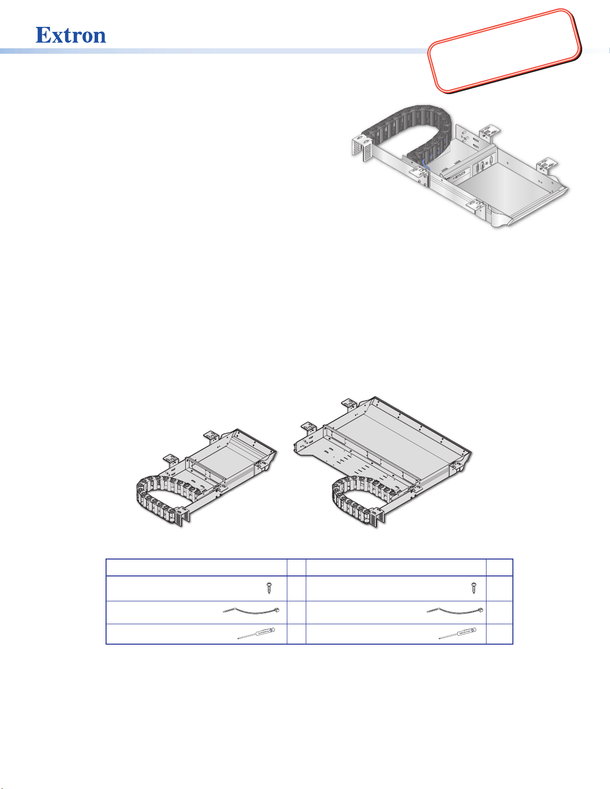
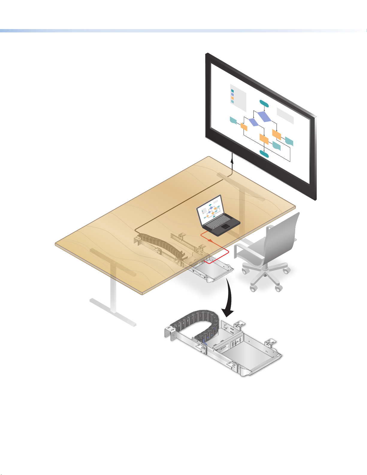
The Cable Cubby Drawers (CCD) are cable access sliding
products that mount underneath furniture for AV connectivity,
control, and power.
USB
Planning
Check with local and state regulations before starting the installation
Ensure that the planned installation complies with national and local building and electrical codes.
Ensure that the planned installation complies with the Americans with Disabilities Act or other accessibility
requirements.
Check all parts and equipment before installation
Ensure that all parts are present in each kit.
Ensure that necessary tools and equipment are available for the installation.
USB
AUDIO
VGA
HDMI
R
CHARGE
Kit Contents
CCD 220 CCD 320
#8 pan-head wood screws 10 #8 pan-head wood screws 10
Cable tie-wraps 6 Cable tie-wraps 10
Tweeker 1 Tweeker 1
CCD 220
1
Page 2
Cable Cubby Drawer CCD 220 and CCD 320 • Installation Guide (Continued)
Application Diagram
USB
AUDIO
VGA
HDMI
USB CHARGER
USB
AUDIO
VGA
HDMI
USB CHARGER
Extron
CCD 220
2
Page 3
Cable Cubby Drawer CCD 220 and CCD 320 • Installation Guide (Continued)
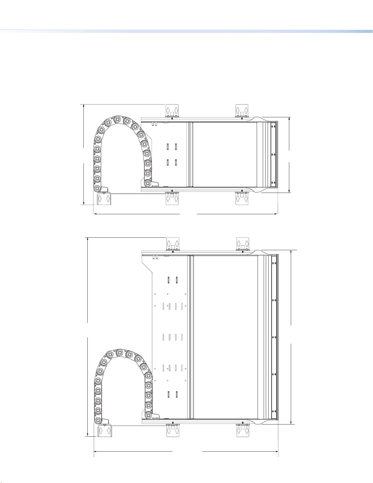
(310.4 mm)
(233.4 mm)
CCD 220 Top View
CCD 320 Top View
Preparing the Table
Determine the best location to install the Cable Cubby Drawer
Ensure that the location where the Cable Cubby Drawer will be installed is convenient for the user.
Ensure that there is ample space under the table to allow for cable management. Reposition the cable track if
space is limited (see Reposition Cable Track on the next page for instructions).
12.21"
22.42"
(569.5 mm)
9.19"
24.21"
(614.9 mm)
21.19"
(538.2 mm)
3
22.42"
(569.5 mm)
Page 4
Cable Cubby Drawer CCD 220 and CCD 320 • Installation Guide (Continued)
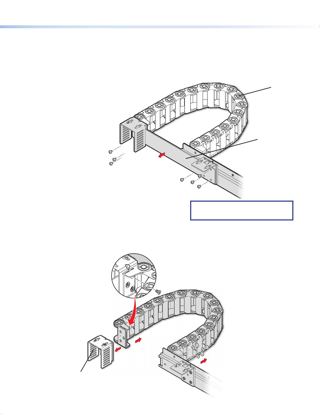
Option 2: Relocate the cable track to the other side of the Cable Cubby Drawer
Perform the same action as in Option 1 and r
washers holding the cable track
Option 1: Reposition the rear cable track by removing the fixed-length cable track bridge arm.
Optional: Reposition Cable Track if Necessary
The drawer’s cable track can be respositioned if space underneath the table is limited.
There are two options to reposition the drawer:
Cable Track
Remove the seven screws
1
holding the bridge arm and
cable track together.
Bridge Arm
1
Remove the bridge arm
2
from its place to allow the
cable track to be repositioned.
emove the cable track bridge arm.
1
NOTE: Before mounting the CCD, open and
close the drawer several times to test for
cable bend issues or resistance.
.
1 Remove the three cable
track screws located behind
the cable track mounting U
bracket.
U bracket
Remove the three nuts and
2
in place.
4
Page 5

Cable Cubby Drawer CCD 220 and CCD 320 • Installation Guide (Continued)
3
mounting feet fr
the cable track unit
with the included
tweeker
attach to the cable track unit.
Remove the chain
.
6 Reattach all mounting
hardware removed in
steps 1 through 3 to
the other side of
the cable track.
om
4 Turn the cable track
unit 180º clockwise.
Reattach the U bracket
to the Cable Track unit.
5 Flip both mounting feet
so they face the drawer,
and re
7
If there is adequate space, reassemble
the bridge arm before mounting
the Cable Cubby Drawer to the table.
Pre-drill mounting holes for the Cable Cubby Drawer
CAUTION: Wear safety glasses when operating power equipment. Failure to comply can result in eye injury.
ATTENTION : Portez des lunettes de sécurité lorsque vous utilisez l’équipement électrique. Ne pas respecter cela peut
conduire à une blessure à l’oeil.
The following instructions apply to both the CCD 220 and CCD 320.
1. Align the included template (the dimensions can also be found on the next two pages) so the front edge of
the template is ush with the edge of the mounting surface. This is where the drawer will open and close.
2. Tape the template if necessary and mark the center of the holes where the Cable Cubby Drawer will be
installed.
3. Drill 3/32” (2.38 mm) diameter pilot holes for the included #8 wood screws, 1/2” (12.7 mm) deep where you
have marked the holes.
5
Page 6

Cable Cubby Drawer CCD 220 and CCD 320 • Installation Guide (Continued)
Mounting
)
(310.1 mm)
Pilot drill 3/32" (2.38 mm) diameter holes,
NOTE: The diagram below is not drawn to scale.
Dimensions and templates are available online at
www.extron.com.
CCD 220
Template
Instructions
1. Align the template so that the “Table Edge”
of the template is ushed with the edge of
the mounting surface.
2. Mark the center of the holes and drill
pilot holes 3/32
1/2
" (12.7 mm) inch deep.
" (2.38 mm) diameter,
1.00"
(25.4 mm)
1/2" (12.7 mm) inch deep
(12 places).
20.64"
(524.3 mm)
12.35"
(313.8 mm)
1.00"
(25.4 mm)
1.00"
(25.4 mm)
3.85"
(97.9 mm)
Table Edge
22.01"
(559.1 mm
0.75"
(19.1 mm)
(271.8 mm)
10.70"
12.21"
6
Page 7

Cable Cubby Drawer CCD 220 and CCD 320 • Installation Guide (Continued)
CCD 320
,
NOTE: The diagram below is not drawn to scale.
Dimensions and templates are available online at
www.extron.com.
0.75"
(19.1 mm)
3.85"
(97.9 mm)
(313.8 mm)
1.00"
(25.4 mm)
12.35"
20.64"
(524.3 mm)
Mounting Template
Instructions
1. Align the template so that the “Table Edge”of the template
is ushed with the edge of the mounting surface.
2. Mark the center of the holes and drill pilot holes 3/32
1/2" (12.7 mm) inch deep.
Pilot drill 3/32" (2.4 mm) diameter holes,
1/2" (12.7 mm) inch deep
(12 places).
"
(2.38 mm) diameter
24.21"
(614.9 mm)
22.70"
(576.6 mm)
TABLE
EDGE
22.01"
(559.1 mm)
7
Page 8

Cable Cubby Drawer CCD 220 and CCD 320 • Installation Guide (Continued)
2
side of the drawer and lift the AAP
frame up and out.
ough
4
with the #4-40 nuts included
with the AAP kits
Preparing the Cable Cubby Drawer
Step 1 — Disassemble the AAP frame from the Cable Cubby Drawer
Remove each screw from the
AAP Frame
1 Remove the bottom screws from
underneath the drawer (3 screws for
the CCD 220 and 5 for the CCD 320).
Step 2 — Attach the AAP modules to the AAP frame
AAP frames allow you to populate the Cable Cubby Drawer with a combination of AAP modules. Follow the steps
below to assemble the connectivity modules of your choice.
Secure the AAP modules
Step 3 — Install Populated AAP frame onto the Cable Cubby Drawer
USB CHARGER
USB
AUDIO
VGA
HDMI
ARGER
CH
USB
3 Position the AAP modules thr
the front of the AAP frame.
5 Reposition and secure the AAP frame
back onto the Cable Cubby Drawer
using the screws removed in Step 1.
USB
AUDIO
VGA
HDMI
8
Page 9

Cable Cubby Drawer CCD 220 and CCD 320 • Installation Guide (Continued)
ews
Step 4: Mounting a Power Supply to the CCD 320 (Optional)
Place one or two power supplies behind the AAP modules as seen in the image below.
A power supply can be mounted in either location or orientation by lining up the mounting holes.
1 Install #4-40 mounting screws through
the bottom holes to secure the power supply.
Step 5: Customize the Front Façade (Optional)
Renish, paint, or add veneer to the façade to complement the furniture, or fabricate a new facade using the
dimensions seen on the next page.
1 Remove the screws holding
the facade to the drawer.
2 Once modied, reattach the facade
to the drawer by using the same scr
removed from Step 1.
Or use the proper hardware or
adhesive for the new facade material
9
Page 10

Cable Cubby Drawer CCD 220 and CCD 320 • Installation Guide (Continued)
0.20"
R= 0.59"
(1.5 mm)
1
the included tweeker to pry open
the aps.
Do this to the entir
(5.0 mm)
8.16"
(207.2 mm)
CCD 220 Front View
R= 0.49"
(1.3 mm)
R= 0.49"
(1.3 mm)
R= 0.49"
(1.3 mm)
2X 125°
1.49"
(37.8 mm)
CCD 220 Side View
0.20"
(5.0 mm)
R= 0.49"
(1.3 mm)
R= 0.49"
(1.3 mm)
R= 0.59"
(1.5 mm)
2X 125°
Figure 1 CCD 220 and CCD 320 Front Facade Dimensions
Route the Cables from the AAP Modules and through the Cable Track
Open the cable track by using
CCD 320 Front View
e cable track.
20.16"
(512.0 mm)
1.49"
(37.8 mm)
R= 0.49"
(1.3 mm)
CCD 320 Side View
1
1
10
Page 11

Cable Cubby Drawer CCD 220 and CCD 320 • Installation Guide (Continued)
2
3
backwar
is attached to simulate
drawer movement.
Reposition any cables if ther
issues with the bend radius
or if the
Strategically tie wrap the cables
to the cable loops on the drawer.
Ensure there is a sufcient
bend radius for the cables.
Move the slide forward and
d where the cable track
222
e are
re is resistance.
Mounting the Cable Cubby Drawer under the Table.
1 Install the included #8 wood screws
in the pre-drilled pilot holes, leaving
1/8 inch (3 mm) of space between the
screw head and the table.
Hang the CCD 220 (320) on the exposed
screws through the CCD slotted
mounting holes.
3 Tighten the screws on one side only.
Open and close the drawer several times
to ensure that the slides have self-adjusted
to a parallel movement and the drawer
moves freely.
Tighten the bracket screws on the other
side.
USB
AUDIO
VGA
HDMI
USB CHARGER
2 Adjust the CCD left or right 9/32"
(7.14 mm) on the slotted hole to secure it.
NOTE: Check the drawer movement for any binding, and adjust the mounting bracket position as required.
11
Page 12

Cable Cubby Drawer CCD 220 and CCD 320 • Installation Guide (Continued)
USB
AUDIO
VGA
HDMI
USB CHARGER
Installation Checklist
Planning (page1)
Check with local and state regulations before starting the installation
Check all parts and equipment before installation
Preparing the Table (page3)
Determine the best location for the Cable Cubby Drawer
Reposition the Cable Track if necessary
Pre-drill mounting holes for the Cable Cubby Drawer
Preparing the Cable Cubby Drawer (page8)
Disassemble the AAP frame from the Cable Cubby Drawer
Assemble the AAP modules to the AAP frame
Install populated AAP frame onto the Cable Cubby Drawer
Mounting the power supply to the Cable Cubby Drawer (Optional)
Customize the Front Facade (Optional)
Cable Management (page9)
Manage the Cables from the Cable Cubby Drawer under the Table
Move the slide forwards and backwards to ensure no resistance
Mounting the Cable Cubby Drawer under the Table (page10)
Install screws and hang the Cable Cubby Drawer under the table
Open and close the drawer to ensure no cable binding or resistance.
Secure the Cable Cubby Drawer
For information on safety guidelines, regulatory compliances, EMI/EMF compatibility, accessibility, and related topics, see the
Extron Safety and Regulatory Compliance Guide on the Extron website.
© 2019 Extron Electronics — All rights reserved. www.extron.com
All trademarks mentioned are the property of their respective owners.
68-3488-50 Rev. A
12 19
 Loading...