

Page 1
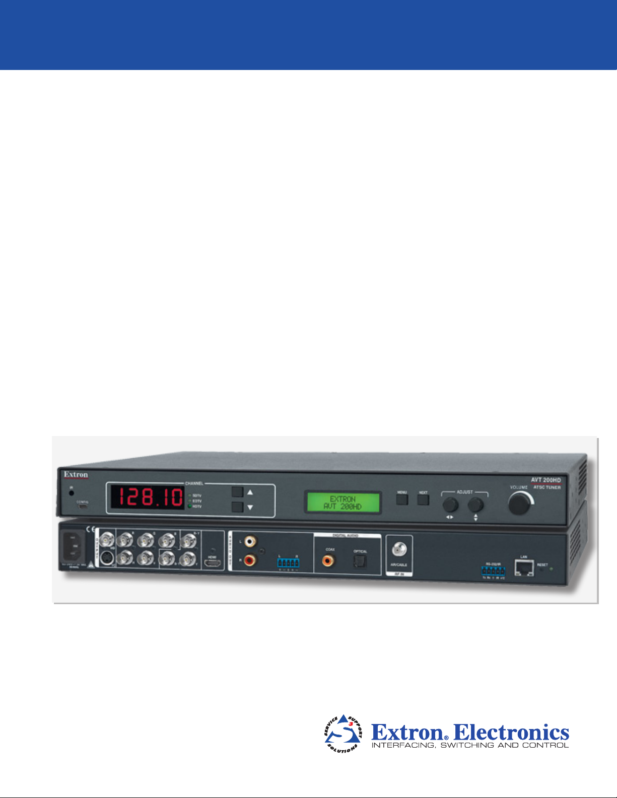
AVT 200HD
ATSC and Cable TV HD Tuner
User Guide
Tuners
68-1834-01 Rev. A
05 11
Page 2

Safety Instructions • English
This symbol is intended to alert the user of important operating and maintenance (servicing) instructions in the literature provided with the equipment.
This symbol is intended to alert the user of the presence of uninsulated
dangerous voltage within the product enclosure that may present a risk of
electric shock.
Caution
Read Instructions • Read and understand all safety and operating instructions before using the equipment.
Retain Instructions • The safety instructions should be kept for future reference.
Follow Warnings • Follow all warnings and instructions marked on the equipment or in the user information.
Avoid Attachments • Do not use tools or attachments that are not recommended by the equipment
manufacturer because they may be hazardous.
Warning
Power sources • This equipment should be operated only from the power source indicated on the product. This
equipment is intended to be used with a main power system with a grounded (neutral) conductor. The third
(grounding) pin is a safety feature, do not attempt to bypass or disable it.
Power disconnection • To remove power from the equipment safely, remove all power cords from the rear of
the equipment, or the desktop power module (if detachable), or from the power source receptacle (wall plug).
Power cord protection • Power cords should be routed so that they are not likely to be stepped on or pinched
by items placed upon or against them.
Servicing • Refer all servicing to qualified service personnel. There are no user-serviceable parts inside. To prevent
the risk of shock, do not attempt to service this equipment yourself because opening or removing covers may
expose you to dangerous voltage or other hazards.
Slots and openings • If the equipment has slots or holes in the enclosure, these are provided to prevent
overheating of sensitive components inside. These openings must never be blocked by other objects.
Lithium battery • There is a danger of explosion if battery is incorrectly replaced. Replace it only with the
same or equivalent type recommended by the manufacturer. Dispose of used batteries according to the
manufacturer instructions.
Consignes de Sécurité • Français
Ce symbole sert à avertir l’utilisateur que la documentation fournie avec le
matériel contient des instructions importantes concernant l’exploitation et la
maintenance (réparation).
Ce symbole sert à avertir l’utilisateur de la présence dans le boîtier
de l’appareil de tensions dangereuses non isolées posant des risques
d’électrocution.
Attention
Lire les instructions• Prendre connaissance de toutes les consignes de sécurité et d’exploitation avant
d’utiliser le matériel.
Conserver les instructions• Ranger les consignes de sécurité afin de pouvoir les consulter à l’avenir.
Respecter les avertissements • Observer tous les avertissements et consignes marqués sur le matériel ou
présentés dans la documentation utilisateur.
Eviter les pièces de fixation • Ne pas utiliser de pièces de fixation ni d’outils non recommandés par le
fabricant du matériel car cela risquerait de poser certains dangers.
Sicherheitsanleitungen • Deutsch
Dieses Symbol soll dem Benutzer in der im Lieferumfang enthaltenen
Dokumentation besonders wichtige Hinweise zur Bedienung und Wartung
(Instandhaltung) geben.
Dieses Symbol soll den Benutzer darauf aufmerksam machen, daß im Inneren
des Gehäuses dieses Produktes gefährliche Spannungen, die nicht isoliert sind
und die einen elektrischen Schock verursachen können, herrschen.
Achtung
Lesen der Anleitungen • Bevor Sie das Gerät zum ersten Mal verwenden, sollten Sie alle Sicherheits-und
Bedienungsanleitungen genau durchlesen und verstehen.
Aufbewahren der Anleitungen • Die Hinweise zur elektrischen Sicherheit des Produktes sollten Sie
aufbewahren, damit Sie im Bedarfsfall darauf zurückgreifen können.
Befolgen der Warnhinweise • Befolgen Sie alle Warnhinweise und Anleitungen auf dem Gerät oder in der
Benutzerdokumentation.
Keine Zusatzgeräte • Verwenden Sie keine Werkzeuge oder Zusatzgeräte, die nicht ausdrücklich vom
Hersteller empfohlen wurden, da diese eine Gefahrenquelle darstellen können.
Avertissement
Alimentations • Ne faire fonctionner ce matériel qu’avec la source d’alimentation indiquée sur l’appareil. Ce
matériel doit être utilisé avec une alimentation principale comportant un fil de terre (neutre). Le troisième
contact (de mise à la terre) constitue un dispositif de sécurité : n’essayez pas de la contourner ni de la
désactiver.
Déconnexion de l’alimentation• Pour mettre le matériel hors tension sans danger, déconnectez tous les
cordons d’alimentation de l’arrière de l’appareil ou du module d’alimentation de bureau (s’il est amovible) ou
encore de la prise secteur.
Protection du cordon d’alimentation • Acheminer les cordons d’alimentation de manière à ce que personne
ne risque de marcher dessus et à ce qu’ils ne soient pas écrasés ou pincés par des objets.
Réparation-maintenance • Faire exécuter toutes les interventions de réparation-maintenance par un
technicien qualifié. Aucun des éléments internes ne peut être réparé par l’utilisateur. Afin d’éviter tout danger
d’électrocution, l’utilisateur ne doit pas essayer de procéder lui-même à ces opérations car l’ouverture ou le
retrait des couvercles risquent de l’exposer à de hautes tensions et autres dangers.
Fentes et orifices • Si le boîtier de l’appareil comporte des fentes ou des orifices, ceux-ci servent à empêcher les
composants internes sensibles de surchauffer. Ces ouvertures ne doivent jamais être bloquées par des objets.
Lithium Batterie • Il a danger d’explosion s’ll y a remplacment incorrect de la batterie. Remplacer uniquement
avec une batterie du meme type ou d’un type equivalent recommande par le constructeur. Mettre au reut les
batteries usagees conformement aux instructions du fabricant.
Vorsicht
Stromquellen • Dieses Gerät sollte nur über die auf dem Produkt angegebene Stromquelle betrieben werden.
Dieses Gerät wurde für eine Verwendung mit einer Hauptstromleitung mit einem geerdeten (neutralen) Leiter
konzipiert. Der dritte Kontakt ist für einen Erdanschluß, und stellt eine Sicherheitsfunktion dar. Diese sollte nicht
umgangen oder außer Betrieb gesetzt werden.
Stromunterbrechung • Um das Gerät auf sichere Weise vom Netz zu trennen, sollten Sie alle Netzkabel aus der
Rückseite des Gerätes, aus der externen Stomversorgung (falls dies möglich ist) oder aus der Wandsteckdose
ziehen.
Schutz des Netzkabels • Netzkabel sollten stets so verlegt werden, daß sie nicht im Weg liegen und niemand
darauf treten kann oder Objekte darauf- oder unmittelbar dagegengestellt werden können.
Wartung • Alle Wartungsmaßnahmen sollten nur von qualiziertem Servicepersonal durchgeführt werden.
Die internen Komponenten des Gerätes sind wartungsfrei. Zur Vermeidung eines elektrischen Schocks
versuchen Sie in keinem Fall, dieses Gerät selbst öffnen, da beim Entfernen der Abdeckungen die Gefahr eines
elektrischen Schlags und/oder andere Gefahren bestehen.
Schlitze und Öffnungen • Wenn das Gerät Schlitze oder Löcher im Gehäuse aufweist, dienen diese zur
Vermeidung einer Überhitzung der empndlichen Teile im Inneren. Diese Öffnungen dürfen niemals von
anderen Objekten blockiert werden.
Litium-Batterie • Explosionsgefahr, falls die Batterie nicht richtig ersetzt wird. Ersetzen Sie verbrauchte Batterien
nur durch den gleichen oder einen vergleichbaren Batterietyp, der auch vom Hersteller empfohlen wird.
Entsorgen Sie verbrauchte Batterien bitte gemäß den Herstelleranweisungen.
Instrucciones de seguridad • Español
Este símbolo se utiliza para advertir al usuario sobre instrucciones importantes de operación y mantenimiento (o cambio de partes) que se desean
destacar en el contenido de la documentación suministrada con los equipos.
Este símbolo se utiliza para advertir al usuario sobre la presencia de elementos con voltaje peligroso sin protección aislante, que puedan encontrarse
dentro de la caja o alojamiento del producto, y que puedan representar
riesgo de electrocución.
Precaucion
Leer las instrucciones • Leer y analizar todas las instrucciones de operación y seguridad, antes de usar el
equipo.
Conservar las instrucciones • Conservar las instrucciones de seguridad para futura consulta.
Obedecer las advertencias • Todas las advertencias e instrucciones marcadas en el equipo o en la
documentación del usuario, deben ser obedecidas.
Evitar el uso de accesorios • No usar herramientas o accesorios que no sean especificamente
recomendados por el fabricante, ya que podrian implicar riesgos.
安全须知 • 中文
这个符号提示用户该设备用户手册中有重要的操作和维护说明。
这个符号警告用户该设备机壳内有暴露的危险电压,有触电危险。
注意
阅读说明书 • 用户使 用该设备前必须阅读并理 解所有安全和 使用说明。
保存说明书 • 用户应保存安全说明书以备将来使用。
遵守警告 • 用户应遵守产品和用户指南上的所有安 全和操作说明。
避免追加 • 不要使 用该产品厂商没有推荐的工具或追加设备,以避免危险。
Advertencia
Alimentación eléctrica • Este equipo debe conectarse únicamente a la fuente/tipo de alimentación eléctrica
indicada en el mismo. La alimentación eléctrica de este equipo debe provenir de un sistema de distribución
general con conductor neutro a tierra. La tercera pata (puesta a tierra) es una medida de seguridad, no
puentearia ni eliminaria.
Desconexión de alimentación eléctrica • Para desconectar con seguridad la acometida de alimentación
eléctrica al equipo, desenchufar todos los cables de alimentación en el panel trasero del equipo, o desenchufar
el módulo de alimentación (si fuera independiente), o desenchufar el cable del receptáculo de la pared.
Protección del cables de alimentación • Los cables de alimentación eléctrica se deben instalar en lugares
donde no sean pisados ni apretados por objetos que se puedan apoyar sobre ellos.
Reparaciones/mantenimiento • Solicitar siempre los servicios técnicos de personal calicado. En el interior no
hay partes a las que el usuario deba acceder. Para evitar riesgo de electrocución, no intentar personalmente la
reparación/mantenimiento de este equipo, ya que al abrir o extraer las tapas puede quedar expuesto a voltajes
peligrosos u otros riesgos.
Ranuras y aberturas • Si el equipo posee ranuras o orificios en su caja/alojamiento, es para evitar el
sobrecalientamiento de componentes internos sensibles. Estas aberturas nunca se deben obstruir con otros
objetos.
Batería de litio • Existe riesgo de explosión si esta batería se coloca en la posición incorrecta. Cambiar esta
batería únicamente con el mismo tipo (o su equivalente) recomendado por el fabricante. Desachar las baterías
usadas siguiendo las instrucciones del fabricante.
警告
电源 • 该设备只能使用产品上标明的电源。 设备必须使用有地线的供电系统供电。 第三条线(
地线)是安全设施,不能不用或跳 过 。
拔掉电源 • 为安全 地从设备拔掉电源,请拔掉所有设备后或桌面电源的电源线,或任何接到市电
系统的电源 线。
电源线保护 • 妥善布线, 避免被踩踏,或重物挤压。
维护 • 所有维修必须由认证的维修人员进行。 设备内部没有用户可以更换的零件。为避免出现触
电危险不 要自己试图打开设备盖子维修 该设备。
通风孔 • 有些设备机壳上有通风槽或孔,它们是用来防止机内敏感元件过热。 不要用任何东西
挡住通风孔。
锂电池 • 不正确的更换电池会有爆炸的危险。必须使 用与厂家推荐的相同或相近型号的电池。按
照生产厂的建议处 理废弃电 池。
ii
Page 3

FCC Class A Notice
This equipment has been tested and found to comply with the limits for a Class A digital device, pursuant to part 15
of the FCC Rules. Operation is subject to the following two conditions:
1. This device may not cause harmful interference.
2. This device must accept any interference received, including interference that may cause undesired operation.
The Class A limits are designed to provide reasonable protection against harmful interference when the equipment
is operated in a commercial environment. This equipment generates, uses, and can radiate radio frequency energy
and, if not installed and used in accordance with the instruction manual, may cause harmful interference to radio
communications. Operation of this equipment in a residential area is likely to cause harmful interference, in which
case the user will be required to correct the interference at his own expense.
NOTE: This unit was tested with shielded cables on the peripheral devices. Shielded cables must be used with
the unit to ensure compliance with FCC emissions limits.
For more information on safety guidelines, regulatory compliances, EMI/EMF compliance, accessibility, and
related topics, click here.
Coaxial Cable
The outer shield of a coaxial cable shall be grounded in accordance with the applicable
provisions of the National Electrical Code ANSI/NFPA 70-2005, Article 820, and Canadian
Electrical Code, Part 1, Section 54.
iii
Page 4

Conventions Used in this Guide
In this user guide, the following are used:
NOTE: A note draws attention to important information.
TIP: A tip provides a suggestion to make working with the application easier.
CAUTION: A caution indicates a potential hazard to equipment or data.
WARNING: A warning warns of things or actions that might cause injury, death, or
other severe consequences.
Commands are written in the fonts shown here:
^AR Merge Scene,,Op1 scene 1,1 ^B 51 ^W^C
[01] R 0004 00300 00400 00800 00600 [02] 35 [17] [03]
E X! *X1&* X2)* X2#* X2!
CE
}
NOTE: For commands and examples of computer or device responses mentioned
in this guide, the character “0” is used for the number zero and “O”
represents the capital letter “o.”
Computer responses and directory paths that do not have variables are written in
the font shown here:
Reply from 208.132.180.48: bytes=32 times=2ms TTL=32
C:\Program Files\Extron
Variables are written in slanted form as shown here:
ping xxx.xxx.xxx.xxx —t
SOH R Data STX Command ETB ETX
Selectable items, such as menu names, menu options, buttons, tabs, and field names
are written in the font shown here:
From the File menu, select New.
Click the OK button.
Copyright
© 2011 Extron Electronics. All rights reserved.
Trademarks
All trademarks mentioned in this guide are the properties of their respective owners.
iv
Page 5

Contents
Introduction............................................................ 1
About this Guide ................................................ 1
About the AVT 200HD Tuner .............................. 1
Features .............................................................. 1
Application Diagram ........................................... 3
Installation .............................................................. 4
Installation Overview ........................................... 4
Rear Panel Features ............................................. 5
Video Output Connectors ............................... 5
Audio Output Connectors ............................... 6
Input Connector ............................................. 7
Remote Configuration and Control
Connectors .................................................... 7
Control Connections ........................................... 8
Ethernet Connection ....................................... 8
Wiring for RS-232 Control .............................. 8
Wiring for IR Control ....................................... 9
Connecting to the USB Port .......................... 10
Operation .............................................................. 13
Front Panel Features .......................................... 13
HDCP Compliance ............................................ 14
Powering On..................................................... 15
Menus on the LCD Screen ................................. 16
Menu System Overview ................................. 16
Channel Setup Menu .................................... 18
Output Configuration Menu ......................... 21
Audio Configuration Menu ........................... 25
Comm Setting Menus ................................... 26
Unit Reset Menu (Resetting from the Front
Panel) .......................................................... 28
Exiting the Menu System ............................... 29
Volume Control ................................................ 29
Resetting from the Rear Panel ........................... 29
Locking and Unlocking the Front Panel
(Executive Modes) ............................................ 31
Using the AVT 200HD IR Remote Control .......... 32
Installing batteries in the AVT 100 Remote .... 33
Buttons on the AVT 200HD Remote
Control ........................................................ 34
Selecting a Channel or Preset Using the IR
Remote Control ........................................... 35
Locking IR Remote Control Access................. 36
Using the On-screen Display (OSD) .................... 36
Introductory Display ..................................... 36
Channel Information Display ......................... 37
Volume Level Display ..................................... 37
Program Guide ................................................. 38
Remote Configuration and Control ................ 39
Serial Port ......................................................... 39
USB Port ........................................................... 39
Ethernet Port .................................................... 39
Ethernet Cable .............................................. 39
IP Address ..................................................... 40
Establishing an Ethernet Connection ............. 40
Connection Timeouts .................................... 40
Using SIS Commands ........................................ 41
Tuner-initiated Messages ............................... 41
V-chip Security for Parental Control ............... 41
Tuner Error Responses ................................... 42
Error Response References ............................ 42
Using the Command/Response Tables for
SIS Commands ............................................. 42
Special Characters ......................................... 43
Symbol Denitions for AVT 200HD Specic
Commands .................................................. 43
Command/Response Table for AVT 200HD
SIS Commands ............................................. 45
Symbol Definitions for IP-specific
Commands .................................................. 56
Command/Response Table for IP-Specific
SIS Commands ............................................. 59
Accessing the AVT 200HD Conguration &
Control Software ............................................. 66
Computer System Requirements ................... 66
Downloading and Installing the Software
from the Web .............................................. 66
Installing the Software from the Disc ............ 67
Starting the Software .................................... 68
Using the Conguration & Control Program
Help File ....................................................... 71
Updating the Firmware ................................. 71
AVT 200HD Tuner • Contents v
Page 6

HTML Configuration
and Control ........................................................... 74
Accessing the Web Pages .................................. 74
Special Characters............................................. 75
System Status Page ........................................... 76
Configuration Pages ......................................... 77
System Settings Page .................................... 77
Tuner Settings Page ....................................... 80
Passwords Page............................................. 83
Firmware Upgrade Page ................................ 84
File Management Page...................................... 86
Uploading Files ............................................. 86
Adding a Directory ........................................ 87
Other File Management Activities .................. 87
Control Pages ................................................... 88
User Control ................................................. 88
Closed Captioning Page ................................ 90
V-Chip Page .................................................. 91
Reference Information ....................................... 95
Specifications .................................................... 95
Part Numbers and Accessories ........................... 98
Included Parts ............................................... 98
Optional Accessories ..................................... 98
Cables .......................................................... 98
Mounting the Tuner .......................................... 99
UL Guidelines for Rack Mounting .................. 99
Rack Mounting Procedure ............................. 99
IP Addressing .................................................. 100
What is an IP Address? ................................ 100
Choosing IP Addresses ................................ 100
Subnet Mask ............................................... 101
Pinging for the IP Address ........................... 101
Connecting as a Telnet Client ...................... 102
Subnetting — A Primer ............................... 104
Frequency Tables ............................................. 106
ATSC Frequency Table ................................. 106
Cable Frequency Table................................. 108
AVT 200HD Tuner • Contents vi
Page 7

Introduction
This section gives an overview of the Extron AVT 200HD ATSC and Cable TV HD Tuner and
describes its significant features. Topics include:
• About this Guide
• About the AVT 200HD Tuner
• Features
• Application Diagram
About this Guide
This guide contains information about the AVT 200HD tuner with instructions for
experienced installers on how to install, configure, and operate the equipment.
In this guide, the terms “AVT,“ “AVT 200HD,” and “tuner” are used interchangeably to
refer to the AVT 200HD tuner.
About the AVT 200HD Tuner
The AVT 200HD is a high performance tuner that receives ATSC over-the-air broadcast
signals and delivers high-definition television (HDTV) video simultaneously on HDMI®,
RGBHV, and YUV outputs. It outputs pulse code modulation (PCM) stereo or Dolby® Digital
surround (AC-3) formatted audio signals with simultaneous S/PDIF digital and analog
balanced and unbalanced stereo. The AVT 200HD also provides clear QAM (unencrypted)
cable (CATV) decoding and standard definition video outputs. Additional integrator and
user-friendly features include a multi-function on-screen display and channel presets.
Features
Some key features of the AVT 200HD are listed below:
• Over-the-air (ATSC) and cable (CATV) channel reception — Delivers high quality
HD video broadcasts from over-the-air ATSC, and clear QAM signals from cable. A full
range of channels are available:
• Over-the-air channels: 2 through 69
• Cable channels: 1 through 135
• Simultaneous HDMI, RGBHV, and HD component video outputs — Selectable
480i, 480p, 720p, and 1080i output rates are available.
• Multiple control options — Can be configured and controlled through the front
panel, an optional IR remote control, or a computer or control system that interfaces
with the AVT via RS-232, Ethernet, or the front panel USB port.
• Multi-function n-screen display — Provides an interface for the user with information
on the currently tuned channel, signal reception strength, and a guide that lists current
and upcoming program information.
• Composite video and S-video outputs — Can be used for standard definition video
display and capture or recording when the AVT is set for 480i output.
AVT 200HD Tuner • Introduction 1
Page 8

• Preset channel selection — Frequently tuned channels can be saved and recalled as
presets. There are 99 presets available.
• Audio and video muting — Audio and video outputs can be muted individually and
simultaneously.
• Aspect ratio control — Can be set for 16x9 or 4x3 output. A 4x3 image on a 16x9
display and vice versa can be shown with black bars or can be stretched or zoomed to
fill the display by changing the output display mode.
• Image freeze control — A live image can be frozen through RS-232, Ethernet, or
optional IR remote control.
• Closed captioning — Closed captioning of broadcasts is available with
customization of the appearance and style of the captions, including font type, size,
and color.
• V-chip — Television programs can be blocked from view based on their movie and
TV ratings. V-chip settings can be configured via Extron Simple Instruction Set (SIS™)
commands or the Windows®-based configuration and control software.
• Front panel security lockout (executive mode) — Locks out front panel functions
if needed for security purposes. (All functions remain available through RS-232, IR, or
Ethernet control.)
• Ethernet control — The AVT 200HD can be controlled, configured, and monitored
over a LAN, WAN, or the Internet. In addition, embedded HTML web pages enable
you to perform functions such as channel selection, volume control, and system
configuration.
• Windows-based configuration and control software — The AVT 200HD
Configuration & Control Program can be used to configure and control the tuner via
RS-232, RS-422, or Ethernet.
• RS-232 configuration and control — The AVT 200HD can be controlled and
configured via a serial interface using the Extron Windows-based control program or
SIS commands.
• USB configuration and control — Enables you to configure the AVT via the front
panel USB port using SIS commands.
• HDCP compliance — Fully supports HDCP-encrypted signals.
• Rack-mountable — The AVT can be mounted on a standard 1U, 19-inch (full rack)
wide metal rack shelf.
• Optional IR remote control — The optional AVT 200HD IR Remote Control (part
number 70-743-01) provides an additional method of controlling the tuner.
• Internal universal power supply — The internal 100-240 VAC, 50-60 Hz,
international power supply provides worldwide power compatibility.
AVT 200HD Tuner • Introduction 2
Page 9
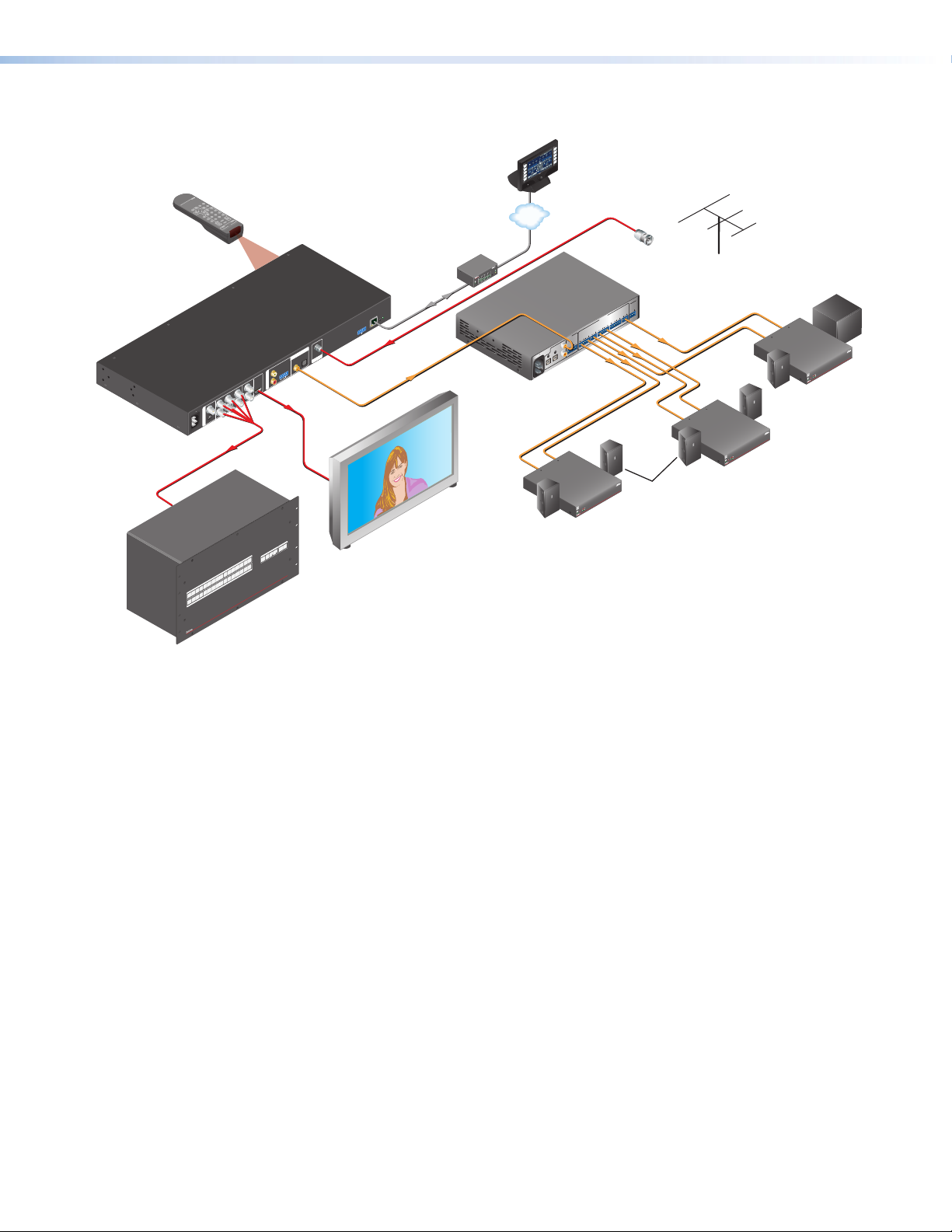
Application Diagram
AVT 200HD Remote
INFO
GUIDE FREEZE
LAST
7 8
0
4
ENTER
9
5 6
CHANNEL SELECTION
SAVE
321
PRESET
VIDEO
CC
TUNE
MUTE
VOLUMECHANNEL
AUDIO
Optional
IR Remote
DIGITAL AUDIO
OPTICAL
COAX
R
A
L
U
L
D
I
O
R
O
U
T
HDMI
G B R-Y
Extron
AVT 200HD
ATSC Tuner
R
VID
O
H V B-Y Y
U
100-240V 0.8A
T
YC
P
U
T
50/60 Hz
RGBHV
16
15
14
16
13
15
12
14
11
INPUTS
13
10
9
12
11
8
7
10
9
6
8
5
OUTPUTS
6 7
3 4
5
2
4
1
3
2
1
HDMI
IO
AUDIO
VIDEO
ESC
CONTROL
VIEW
PRESET
ENTER
™
P
SERIES
ADS
WITH
ULTRA
CROSSPOINT
ULTRA-WIDEBAND MATRIX SWITCHER
Extron
CrossPoint Ultra Series
Ultra-Wideband Matrix Switcher
VCR
DVD
DOC
CAM
LAPTOP
PC
ON
OFF
DISPLAY
MUTE
SCREEN
UP
SCREEN
DOWN
Extron
TouchLink
Control
System
TCP/IP
®
100
RELAY
LINK
ACT
31
INPUT
3
IR
1
42
3
COM
RX
1
4
TX
2
IPL 250
1
4
2
2
R
3
IP
LAN
RESET
RS-232/IR
+12V
Rx
Tx IR
AIR/CABLE
RF IN
RF
S/PDIF
Extron
SSP 7.1
Surround Sound
Processor
Left and
Right Front
Flat Panel Display
100-240V 0.5A
50-60Hz
1
Extron
XPA 1002
Power
Amplier
DIGITAL
3
4
2
™
or
Cable
Feed
SSP 7.1
RS-232
SUB
TxRx
WOOFER
RB SUB
BACK
OUTPUTS
LB/CB
RS
SURROUND
LS
CENTER
C
R
FRONT
L
INPUTS
ANALOG
R
5
L
Left and Right
Surround
Extron
XPA 1002
2
1
LIMITER/PROTECT
SIGNAL
OVER
TEMP
SI 26
Surface-mount
Speakers
Antenna
Center
and
Subwoofer
Extron
XPA 1002
Power
Amplier
Extron
XPA 1002
Power
Amplier
XPA 1002
12
LIMITER/PROTECT
SIGNAL
OVER
TEMP
Extron
SI 26
Surface-mount
Speaker
XPA 1002
2
1
LIMITER/PROTECT
SIGNAL
OVER
TEMP
Figure 1. Application Diagram for the AVT 200HD
AVT 200HD Tuner • Introduction 3
Page 10

Installation
This section describes the rear panel of the AVT 200HD and provides instructions for cabling.
It covers the following topics:
• Installation Overview
• Rear Panel Features
• Control Connections
Installation Overview
Follow these steps to install and set up the AVT 200HD tuner:
1. Disconnect power from the tuner and turn off all other devices that are connected to
it.
2. (Optional) Mount the unit in a rack. Rack mount the tuner using the supplied
brackets (see the “Mounting the Tuner” in the “Reference Information” section).
3. Connect the RF input. Connect an antenna or a CATV cable to the RF In F-type
connector (j on the rear panel diagram on the next page).
4. Connect the video output. Connect a television or other output device to one of
the following video output connectors:
• VID — Composite video (
• YC — S-video (
• RGBHV — RGBHV (
• Component video — YUVp/HD or YUVi (
• HDMI — HDMI digital (
5. Connect the audio output. Connect a speaker set, amplifier, receiver, or other
audio output device to one or more of the following connectors:
• RCA — Unbalanced analog (
• Captive screw — Balanced or unbalanced analog (
diagram)
• Coax — Digital S/PDIF (
• Optical — (Fiber optic) Digital S/PDIF (
6. Connect control devices: Connect your computer to one of these AVT ports to
configure and control the tuner via the Windows®-based software or SIS commands.
• RS232 port — Serial RS-232 control (
• LAN Ethernet port — Ethernet control via Internet browser (
diagram)
• Config port — USB connection (
“Operation” section)
7. Connect power to the AVT by connecting a standard IEC power cord (provided) from
a 100 to 240 VAC, 50-60 Hz power source to the AC power receptacle (a on the rear
panel diagram).
, top, on the rear panel diagram)
b
, bottom, on the rear panel diagram)
b
c on the rear panel diagram
on the rear panel diagram
d
on the
e
on the rear panel diagram)
h
rear panel diagram
on the rear panel diagram)
f
on the rear panel diagram)
i
on the rear panel diagram)
k
on the front panel diagram in the
b
)
)
on the rear panel
g
on the rear panel
l
)
AVT 200HD Tuner • Installation 4
Page 11
Rear Panel Features
GB
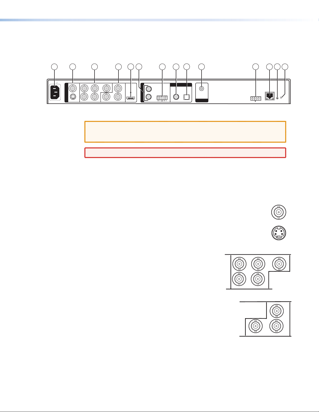
All of the AVT 200HD connectors are on the rear panel. The following figure shows the AVT
rear panel features.
1
100-240V 0.8A
50/60 Hz
2 3
O
U
VID
T
P
U
YC
T
4
R
GB R-Y
HV B-Y Y
Figure 2. AVT 200 Rear Panel
CAUTION: Use electrostatic discharge precautions (be electrically grounded) when
making connections. Electrostatic discharge (ESD) can damage equipment,
although you may not feel, see, or hear it.
WARNING: Remove power from the system before making any connections.
a AC power connector — Plug a standard IEC power cord into this connector to connect
the tuner to a 100 VAC to 240 VAC, 50 or 60 Hz power source.
Video Output Connectors
b Composite and S-video stacked video output connectors —
• VID (top): Connect a composite video output device to this female BNC
connector.
• YC (bottom): Connect an S-video output device to this female 4-pin mini
DIN connector.
These connectors output simultaneously when the 480i output rate is selected.
HDMI
6
5
A
U
D
I
O
R
O
U
T
7
LLR
8
DIGITAL AUDIO
COAX
OPTICAL
9
10
AIR/CABLE
RF IN
11
RS-232/IR
Rx
Tx IR+12V
12
13
14
LAN
RESET
VID
YC
c
RGBHV output connectors — Connect an RGBHV
output device to these five female BNC connectors. This
output supports 480i, 480p, 720p, and 1080i resolutions.
d Component video output connectors — Connect an
HD YUV output device to these three female BNC connectors.
These outputs support 480i, 480p, 720p, and 1080i resolutions.
AVT 200HD Tuner • Installation 5
R
HV
R-Y
B-Y Y
Page 12
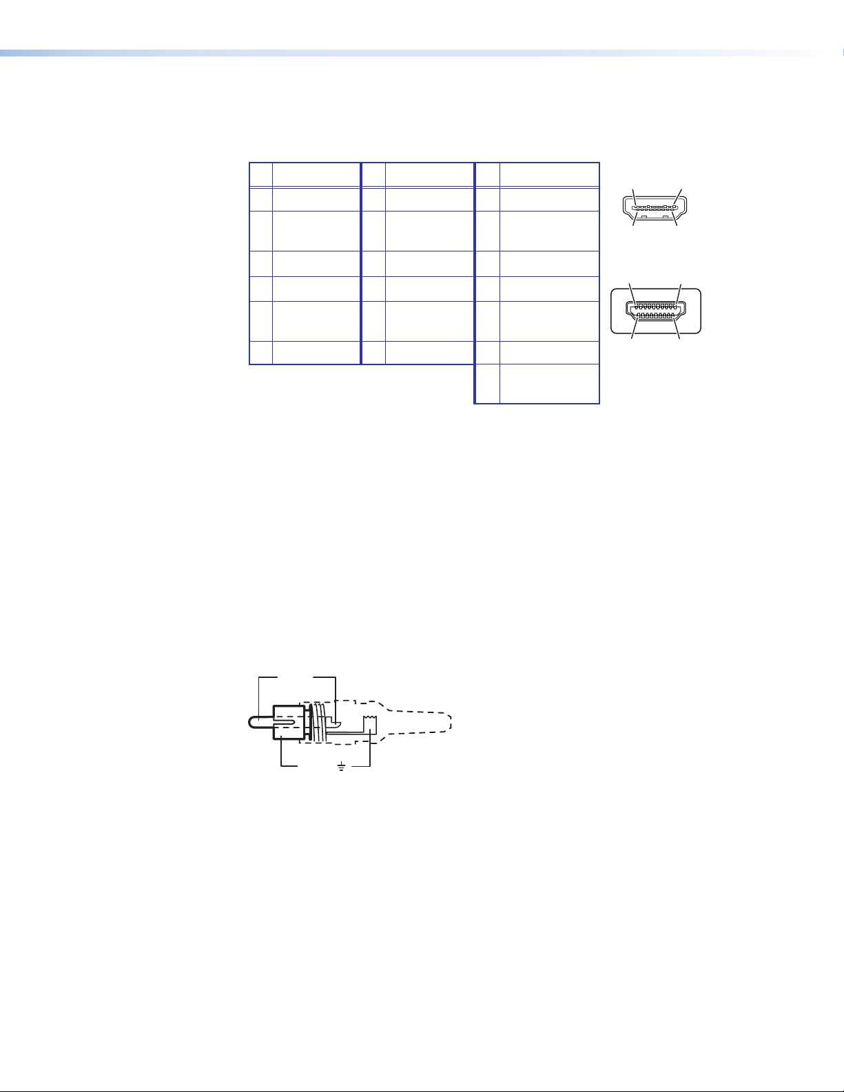
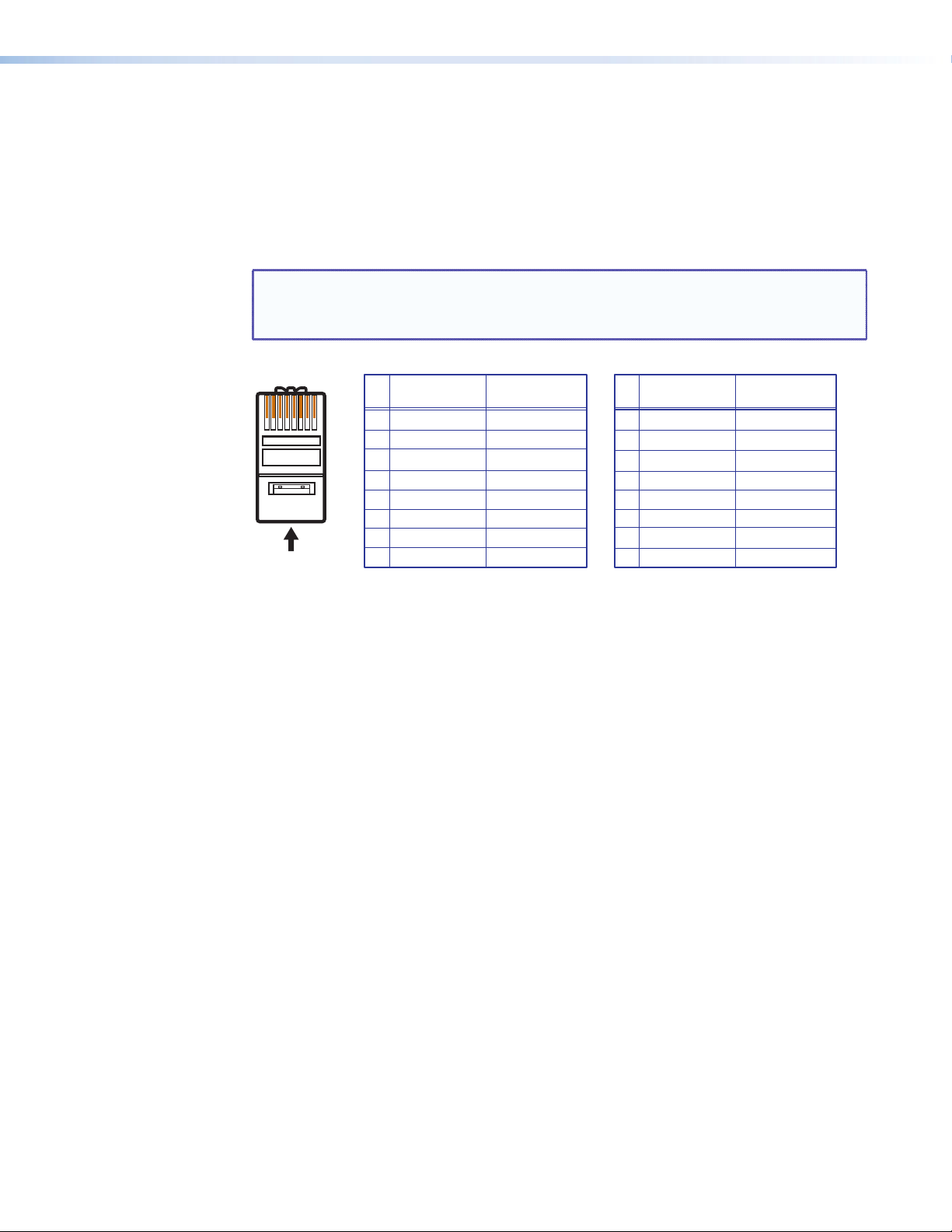
e HDMI video output connector — Connect an HDMI output device to this female
HDMI connector for digital video output. This output supports 480p, 720p, and 1080i
resolutions. The table below shows the pin assignments for this connector.
Pin
Signal
1 TMDS data 2+ 7 TMDS data 0+ 13 CEC
2 TMDS data 2 8 TMDS data 0 14 Reserved
shield shield (NC on device)
3 TMDS data 2– 9 TMDS data 0– 15 SCL
4 TMDS data 1+ 10 TMDS clock+ 16 SDA
5 TMDS data 1 11 TMDS clock 17 DDC/CEC
shield shield ground
6 TMDS data 1– 12 TMDS clock– 18 +5 V power
19
Pin Signal
Pin
Signal
Hot plug
detect
HDMI
HDMI
1
19
182
19
18 2
Type A Receptacle
1
Type A Plug
An Extron LockIt™ cable lacing bracket is provided with the AVT to enable you to secure
the HDMI device cable to this output connector to prevent intermittent or complete
signal loss due to a loose cable connection. Above the connector is a hole into which
an HDMI connection mounting screw (provided) can be inserted to attach the lacing
bracket to the AVT rear panel. (See the provided LockIt HDMI Lacing Bracket Installation
Guide card for information on attaching the bracket.)
Figure 3. HDMI Connector Pin Assignments
Audio Output Connectors
Analog audio output connectors
f Audio output RCA connectors — Connect a speaker set or other audio output device
to these RCA connectors for balanced or unbalanced analog audio output.
Tip (+)
Sleeve ( )
Figure 4. Wiring an RCA Connector
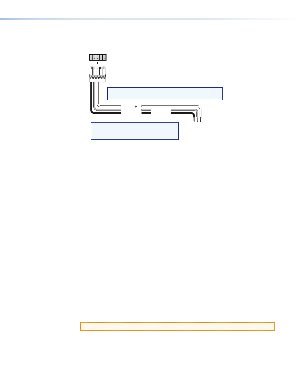
g Audio output captive screw connector — Connect a speaker set or other audio
output device to this 3.5 mm 5-pole captive screw connector for balanced or
unbalanced analog audio output (see the illustration on the next page).
AVT 200HD Tuner • Installation 6
Page 13

Tip
COAX
OPTICAL
Ring
Sleeve(s)
Tip
Ring
LR
NO Ground Here
NO Ground Here
Tip
Sleeve(s)
Tip
LR
Balanced Audio Output
CAUTION:
For unbalanced audio, connect the sleeves to the
Do not tin the wires!
ground contact.
DO NOT connect the sleeves to negative (–) contacts.
Figure 5. Wiring the Captive Screw Audio Connector
Digital audio output connectors
Both digital ports support AC-3 and PCM digital audio.
Coax port — Connect a digital audio output device to this coaxial RCA jack for
h
S/PDIF signal transmission.
i Optical port — Connect a digital audio output device to this TOSLINK
optic connector for S/PDIF signal transmission.
Input Connector
j Air/Cable RF In connector — Plug an antenna or a CATV cable into this
F-type connector for over-the-air or cable radio frequency (RF) input.
Remote Configuration and Control Connectors
The following connectors are available for remote configuration and control of the
AVT 200HD from a computer or other control system or via IR remote control.
Unbalanced Audio Output
™
fiber
AIR/CABLE
RF IN
RS-232/IR connector — Connect a host device, such as a computer, touch panel
k
control system, or RS-232 capable PDA to this 5-pole captive screw connector for
entering SIS commands and using the Windows-based control software (see “Wiring
for RS-232 Control” later in this section, for information on connecting to this port).
To extend IR control, you can also connect an optional IR Link to this port (see “Wiring
for IR Control,” later in this section).
l LAN port — If desired, connect the AVT 200HD to a computer or to an Ethernet
LAN via this RJ-45 connector. Through this port, you can control the tuner using SIS
commands, the AVT 200HD Configuration & Control Program, or the HTML pages
that are pre-loaded on the AVT (see “Ethernet Connection,” on the next page).
The two LEDs on this connector indicate the status of the Ethernet
LAN
connection. The amber activity LED indicates that the RJ-45
connector is transmitting or receiving data. This LED flickers as the
Activity
Link
tuner communicates. The green link LED indicates that the AVT is
properly connected to an Ethernet LAN. This LED lights steadily.
m Reset button — This recessed button initiates four reset modes on the AVT 200HD. To
select a reset level, use a pointed object such as a small Phillips screwdriver to press and
hold the button while the AVT is running or while it is powering up (see “Resetting
from the Rear Panel” in the “Operation” section).
n Reset LED — When you are selecting a reset mode, this LED blinks the appropriate
number of times to indicate the level of reset or that the reset is complete.
AVT 200HD Tuner • Installation 7
Page 14
Control Connections
Ethernet Connection
When you connect a computer to the AVT 200HD LAN port, it is vital that you use the
correct Ethernet cables, and that they are properly terminated with the correct pinout.
Ethernet links use Category (CAT) 5 or 5e unshielded twisted pair (UTP) cables, terminated
with RJ-45 connectors. Ethernet cables are limited to a length of 328 feet (100 m).
NOTES: • Do not use standard telephone cables. Telephone cables do not support
Ethernet or Fast Ethernet.
• Do not stretch or bend the cables, because this can cause transmission errors.
Pins:
12345678
Insert Twisted
Pair Wires
RJ-45
Connector
Crossover Cable
Pin
2
3
4
5
6
7
A cable that is wired as T568A at one end
and T568B at the other (Tx and Rx pairs
reversed) is a "crossover" cable.
End 1 End 2
Wire color
1
White-green
Green
White-orange
Blue
White-blue
Orange
White-brown
8
Brown
T568A
Wire color
White-orange
Orange
White-green
Blue
White-blue
Green
White-brown
Brown
T568B
Straight-through Cable
End 1 End 2
Wire color
Pin
1
2
3
Blue
4
White-blue
5
6
White-brown
7
Brown
8
T568B
A cable that is wired the same at both ends
is called a "straight-through" cable, because
no pin or pair assignments are swapped.
Wire color
White-orangeWhite-orange
OrangeOrange
White-greenWhite-green
Blue
White-blue
GreenGreen
White-brown
Brown
T568B
Figure 6. RJ-45 Connector and Pinout Tables
The cable that you use depends on your network speed. The tuner supports both
10 Mbps (10Base-T — Ethernet) and 100 Mbps (100Base-T — Fast Ethernet),
half-duplex and full-duplex, Ethernet connections.
• 10Base-T Ethernet requires CAT 3 UTP or STP cable at minimum.
• 100Base-T Fast Ethernet requires CAT 5e UTP or STP cable at minimum.
The Ethernet cable must be properly terminated for your application as either a
crossover or a straight-through cable.
• Crossover cable — Direct connection between the computer and the AVT 200HD
• Patch (straight-through) cable — Connection of the AVT to an Ethernet LAN
Wiring for RS-232 Control
To connect your computer or control system to the AVT RS-232 connector, use an Extron
Universal Control cable (UC50' or UC100'; see “Cables” in the “Reference Information”
section for part numbers) or other female 9-pin-to-bare-wire RS-232 cable.
1. Wire the unterminated end of the RS-232 cable to the 5-pole captive screw connector,
provided with the AVT. Use only the first three pins on the connector, starting from the
left:
a. Connect the transmit wire to the first pin on the left, which plugs into the Tx
(Transmit) port.
b. Connect the receive wire to the second pin, which plugs into the Rx (Receive) port.
c. Connect the ground wire to the third pin, which plugs into the ground port, marked
with _.
AVT 200HD Tuner • Installation 8
Page 15
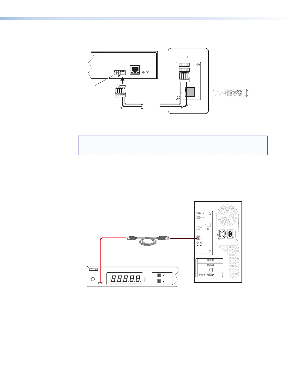
2. Plug the wired 5-pole connector into the RS-232/IR receptacle on the AVT 200HD rear
panel.
RS-232/IR
Tx Rx IR +12V
NOTE: Connect a ground wire between the AVT 200HD
AVT 200HD Tuner
Rear Panel
RS-232/IR Port
and the computer or control system.
NOTE: If you use cable that has a drain
Figure 7. Remote RS232/IR Connector Pin Assignments
In the “Remote Configuration and Control” section, see “Using SIS Commands” for
definitions of the SIS commands and “Accessing the AVT 200HD Configuration and
Control Software” for details on how to install and use the program.
Wiring for IR Control
You can control the AVT 200HD by pointing the IR remote control at the front panel IR
sensor and pressing the desired button (see “Using the AVT 200HD IR Remote Control”
in the “Operation” section for more information). However, if the AVT is located where its
IR sensor is not in direct line of sight of the remote control, you can connect an IR Link to
enable the IR signal from the remote control to reach the AVT.
Wiring the IR Link
The optional IR Link Infrared Signal Repeater can be connected directly to an AVT 200HD. To
wire the IR Link for use with the AVT 200HD:
1. Prepare the site and install a wall box, following the directions in the IR Link user guide,
provided with the IR Link equipment.
2. Cut a length of 150 feet (45 m) or less of Extron Comm-Link (CTL or CTLP) cable to go
between the AVT and the IR Link.
3. Attach a 3.5 mm, 5-pole captive screw plug (provided) to each end of the cable. Only
three wires (between pins A, B, and D on the IR Link end, and the ground, IR, and
+12 V pins of the AVT 200HD RS-232/IR connector) are used. Wire the cable as shown
below. Connectors are included with the IR Link, but the cable is purchased separately
(see “Cables” in the “Reference Information” section for cable part numbers).
4. Plug the 5-pole connector into one of the IR Link communication connectors.
5. Connect the other end of the cable to the RS-232/IR port on the AVT rear panel.
Ground ( )
Receive (Rx)
Transmit (Tx)
Transmit (Tx)
Receive (Rx)
wire, tie the drain wire to ground
at both ends.
Computer or
Control System
RS-232 Port
CAUTION: Do not connect more than one IR Link (in parallel or in series) to the AVT.
AVT 200HD Tuner • Installation 9
Page 16
The following diagram shows how to wire the AVT 200HD to use the infrared remote
A
control with the optional IR Link.
RS-232/IR
Rx
Tx IR +12V
AVT 200HD Rear Panel
RS-232/IR Port
Figure 8. Connecting the AVT 200HD to the IR Link
NOTE: The ground pin of this connector is shared between RS-232 and IR
communication. If using the IR Link, you cannot use this port simultaneously for
an RS-232 connection, and vice versa.
Connecting to the USB Port
The mini Type B USB port is located on the AVT front panel. It can be used to configure the
tuner via SIS commands or the Configuration & Control software.
1. Connect a USB A to mini B cable between the USB Config port on the AVT front panel
and the USB port on your computer.
LAN
RESET
CC
SAVE
ENTER
FREEZE
AUDIO
VOLUMECHANNEL
9
SHIFT
AVT 200HD Remote
0
GUIDE
43215678
CHANNEL SELECTION
LAST
INFO
12
+12 VDC
IR
Modulated IR
Ground ( )
MUTE
TUNE
PRESET
VIDEO
A
D
B
AVT 200HD Remote Control
IR Link Rear Panel
Mini Type B
USB
USB Cable
IR
CONFIG
CHANNEL
SDTV
EDTV
HDTV
VT 200HD Front Panel
Figure 9. USB Port Connection
Type A
USB
USB 1
USB
Ports
Computer
AVT 200HD Tuner • Installation 10
Page 17
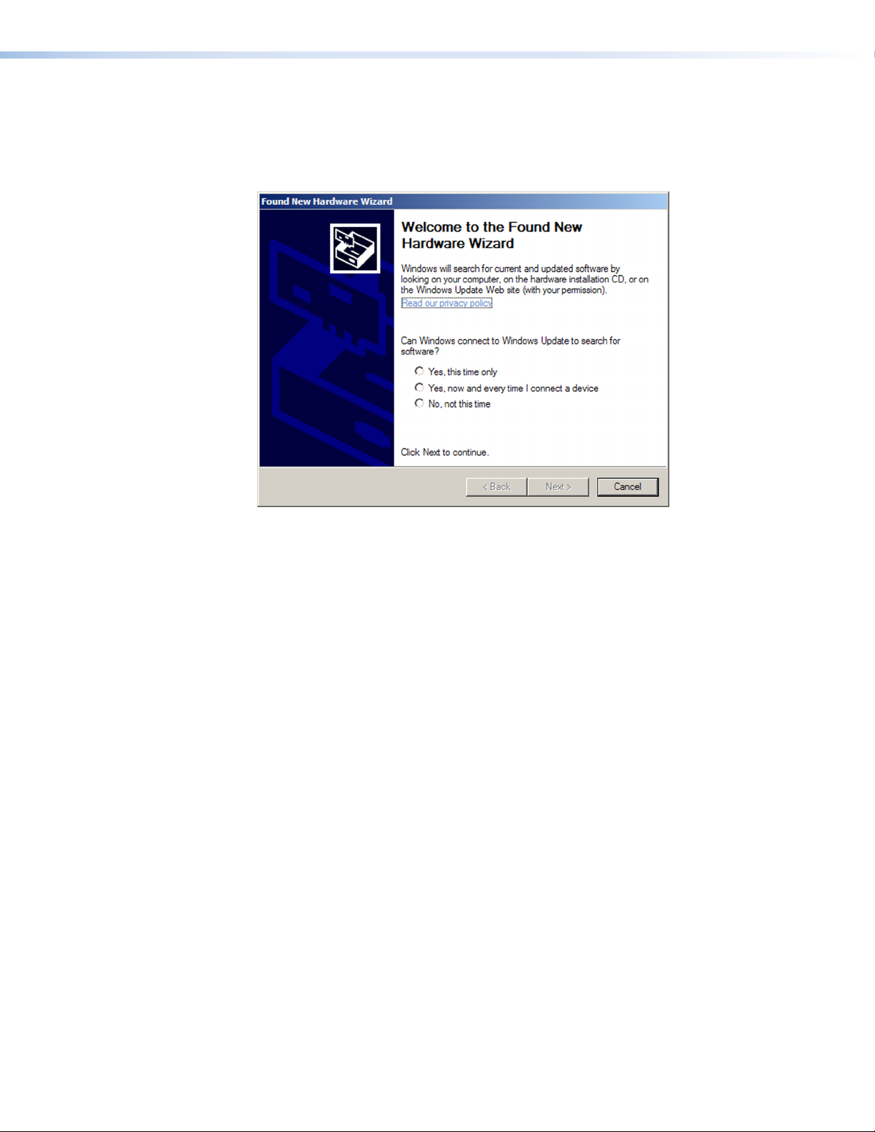
2. If this is the first time you have connected an AVT 200HD to this USB port on your
computer, the Found New Hardware Wizard opens. On the first screen, specify whether
you want the computer to connect to Windows Update in order to search the web
for the driver that it needs to communicate with the AVT via the USB port. (This is not
necessary if the USB driver already exists on your computer.)
Figure 10. Found New Hardware Wizard Opening Screen
• Select the Yes, this time only radio button if you want your computer to
connect to Windows Update only this one time.
• Select Yes, now and every time I connect a device if you want the computer to
automatically connect to Windows Update to search the web every time the AVT is
connected to this USB port.
• Select No, not this time if you do not want the computer to connect to Windows
Update to search the web at this time (for example, if the driver is already on your
computer).
AVT 200HD Tuner • Installation 11
Page 18
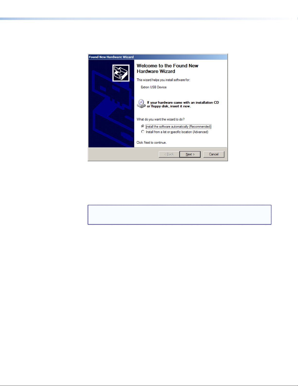
3. Click Next. On the next screen, make sure that the Install the software
automatically (Recommended) radio button is selected, then click Next. (You do not
need to insert a disc.)
Figure 11. Selecting the Radio Button to Install the USB Driver Automatically
Your computer locates the driver needed for it to communicate with the AVT 200HD
via the USB port. This driver is loaded to the computer hard drive when the AVT
configuration program is installed.
4. When the Completed screen appears, click Finish to close the wizard.
NOTE: This wizard appears only the first time you connect the AVT to each USB
port. You do not see the wizard again unless you connect the AVT to a
different USB port on your computer.
5. Configure the AVT as desired, using SIS commands or the AVT 200HD Configuration
and Control Program (see the “Using SIS Commands” section for information on
available commands, or see the configuration and control program help file).
AVT 200HD Tuner • Installation 12
Page 19

Operation
This section describes the AVT 200HD front panel controls and the procedures for using
them to configure and operate the AVT tuner. Topics include:
• Front Panel Features
• Powering On
• Menus on the LCD Screen
• Resetting from the Rear Panel
• Locking and Unlocking the Front Panel (Executive Modes)
• Using the AVT 200HD IR Remote Control
Front Panel Features
1
2
IR
CONFIG
3
4
CHANNEL
SDTV
EDTV
HDTV
5
6
7
MENU
NEXT
8
9
ADJUST
10
VOLUME
AVT 200HD
ATSC TUNER
Figure 12. AVT 200HD Front Panel
IR receiver — This sensor receives commands via infrared signals from the optional AVT
a
200HD IR Remote Control (see “Using the AVT 200HD IR Remote Control,” later in
this section).
Config port — Connect a USB cable (USB A to mini B) between your computer and
b
this port to configure and control the AVT via SIS commands or the Windows-based
configuration and control software, and to update the firmware.
c LED display — This 5-digit, alphanumeric LED display indicates the over-the-air TV or
CATV channel being received (in tune mode) or the selected channel preset (in preset
mode).
d TV format indicator LEDs — These three green LEDs light to indicate the digital
television format of the input signal. The following resolutions are supported:
SDTV — 480i
EDTV — 480p
HDTV — 720p and 1080i
When no TV signals are detected, none of these LEDs light.
AVT 200HD Tuner • Operation 13
Page 20

e Up (
LCD window — This window displays messages, menu information, and your menu
f
Menu button — Press this button to access the AVT 200HD menu system and step
g
Next button — Within a menu, press this button to step through the submenus.
h
Adjustment knobs — Within a submenu, turn these horizontal and vertical
i
) and Down (<) buttons — These buttons change the channel or preset,
>
depending on the selected operating mode. Each press increments or decrements the
number in the LED display (c).
• In Tune mode (default): The buttons select channel numbers to switch channels
that have saved in the channel list (either manually or by Auto-Scan; see “Scanning
for Channels,” later in this section).
• In Preset mode: The buttons select the preset numbers to switch channels that
have been saved as presets.
Pressing and holding a button causes the displayed numbers to cycle up or down rapidly.
When you release the button, the channel or preset number that appears in the LED
display is selected.
selections (see “Menus on the LCD Screen,” later in this section, for information on
using the AVT menu system).
through the menus.
Adjustment knobs to select options from the submenu, such as the output resolution or
the RF source (Air or Cable).
j Volume knob — Turn this knob to adjust the output volume between 0% (muted) and
100%.
HDCP Compliance
When a broadcast flag, indicating protected material, is detected in the television data
stream, the LCD screen on the front panel displays an asterisk (*) in the lower-right corner
(see the example below).
The AVT 200HD immediately disables any analog video and audio outputs.
For an HDMI connection, the AVT checks the EDID of the connected display and outputs
HDMI video or audio only if the monitor is HDCP-compliant.
Analog video and audio resume when the broadcast flag is removed.
NOTE: If you not in a position to view the front panel LCD screen, you can check
NOTE: This knob adjusts volume for analog and PCM digital output only. It does not
affect Dolby digital (AC-3) volume.
NBC–4LA
AIR 4–1
whether the broadcast flag is on or off by entering the SIS command
E
I HDCP}. The system responds with 0 if the broadcast flag is off or 1 if it is
on.
See the View broadcast flag command in the “Remote Configuration and
Control” section for more information.
*
AVT 200HD Tuner • Operation 14
Page 21

Powering On
Apply power by connecting the provided IEC power cord to the rear panel IEC connector
and to an AC source. The tuner performs a self-test that flashes the three TV format
indicators in order from top to bottom and then turns them off while the initial two
power-up screens are displayed in the LCD screen. At the completion of the self-test, the LED
display shows the current channel, the appropriate TV format LED is lit, and the LCD window
displays the default screen cycle.
If an error occurs during the self-test, the AVT locks up and does not operate. If this
occurs, call the Extron S3 Sales & Technical Support Hotline. See the rear cover for contact
information in your area.
When power is first applied to the AVT, the LCD screen displays Extron Electronics, then
AVT 200HD with the current firmware version. If the AVT self-test completes successfully, the
default cycle begins, in which the display alternates between a screen showing the current
output resolution and refresh rates and a screen showing the channel to which the AVT is
currently tuned. These two screens continue to cycle on the screen when the menu system is
not in use.
NOTE: Audio and video mute settings are not retained when power is cycled to the
AV T.
The flow diagram on the next page shows the order in which the screens appear at
power-up.
Power
On
EXTRON
ELECTRONICS
AVT 200HD
VERSION 1.00
NBC-LA
AIR 4-1
OUTPUT
480i @ 59.94
or
Default Cycle
Preset01
AIR 4-1
Figure 13. Power-up and Default Cycle Screens (Example)
NOTE: If your AVT 200HD is new and no channel scan
has been performed, the two screens shown at
right alternate on the LCD screen instead of the
default cycle (see “Scanning for
channels,” later in this section).
This cycle also appears after a system reset
(see “Unit Reset Menu (Resetting from the
Front Panel),” later in this section.) After the
first scan the default cycle is displayed after power-up.
AIR CHANNEL
LIST EMPTY
PRESS UP BUTTON
TO START SCAN
AVT 200HD Tuner • Operation 15
Page 22

Menus on the LCD Screen
The AVT 200HD menus that are displayed on the LCD screen enable you to configure and
operate the tuner from the front panel. The menu navigation buttons (Menu and Next) are
located to the right of the LCD window. Press these buttons to cycle through the available
menus, submenus, and options.
Menu System Overview
The menu system consists of five menus, some of which have submenus (see the menu
flow diagram on the next page).
Using the menus
Access the different levels of menus using the Menu and Next buttons and the Adjustment
knobs as follows:
1. To access the menu system, press the Menu button. The first menu name (Channel
Setup) is displayed on the LCD screen.
2. Select a menu by repeatedly pressing the Menu button until the desired menu name is
displayed.
3. When you see the menu that you want, press the Next button repeatedly to cycle
through its submenus.
4. When the desired submenu is displayed, rotate the horizontal ([) or vertical ({)
Adjustment knob clockwise or counterclockwise to cycle through the submenu options.
If you want to return to a menu from within one of its submenus, press Menu.
5. When the desired option is displayed, do one of the following to implement it:
• Press Next to display another submenu.
• Press Menu repeatedly until the Press Next to Exit screen appears, then press
Next to return to the default cycle.
• Do nothing more, and wait until the LCD screen returns to the default cycle
(approximately 30 seconds).
Your selections are automatically saved.
AVT 200HD Tuner • Operation 16
Page 23
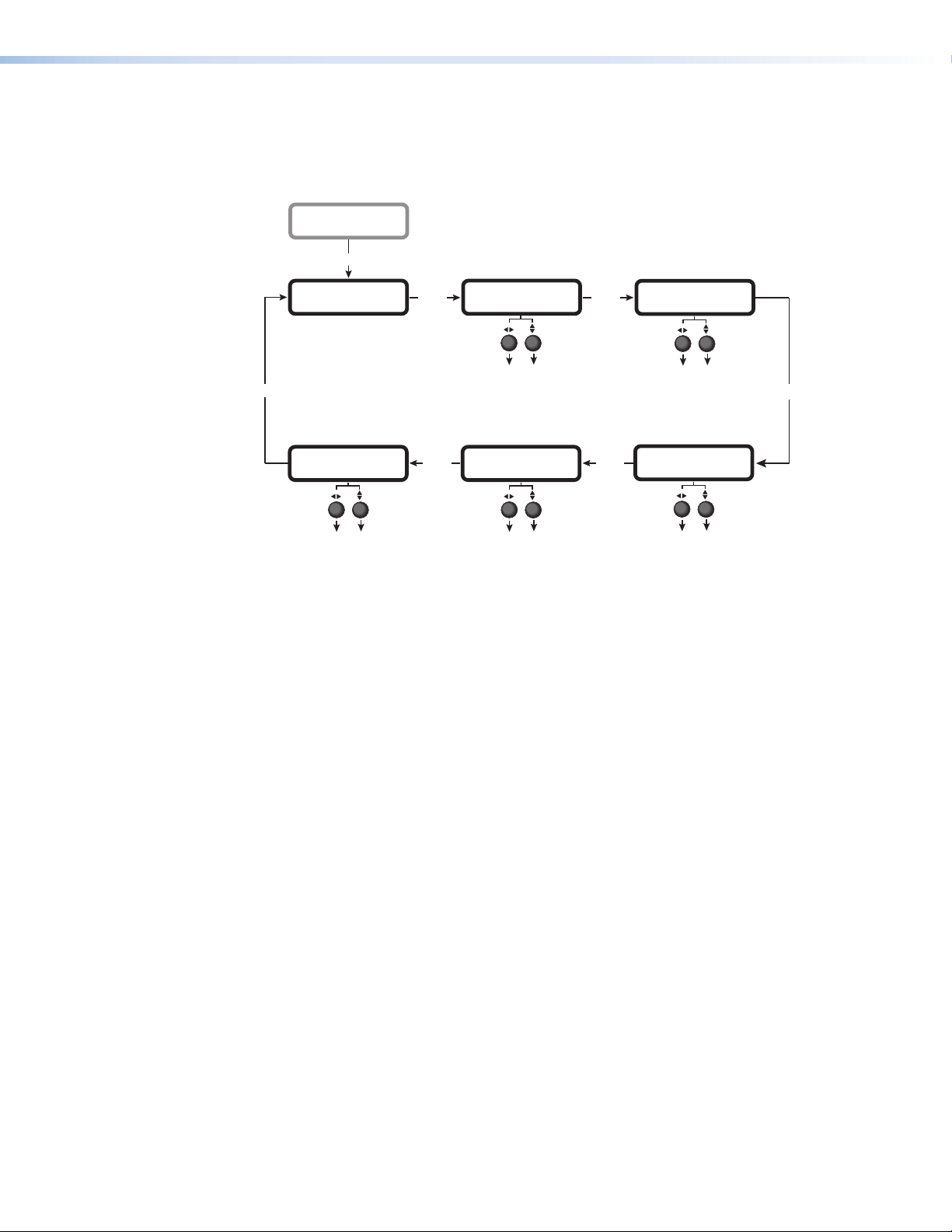
Menu flow diagram
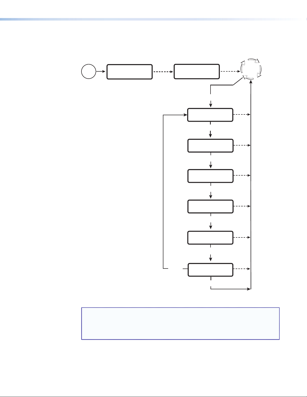
The following diagram shows the menus that are displayed in the front panel LCD window
and the order in which they appear when you repeatedly press the Menu button.
Power
On
EXTRON
ELECTRONICS
2 sec.
AVT 200HD
VERSION X.XX
Menu
CHANNEL
SETUP
Menu
OUTPUT
CONFIGURATION
Menu
AUDIO
CONFIGURATION
Menu
VIEW
COMM SETTING
2 sec.
Default
Cycle
30 sec.
30 sec.
30 sec.
30 sec.
Menu
Menu
UNIT
RESET
Menu
PRESS NEXT
TO EXIT
Next
30 sec.
30 sec.
Figure 14. AVT 200HD Menu Flow
NOTE: The menus time out and the default cycle is displayed after 30 seconds of
inactivity; however, any selections you made with the Adjustment knobs are
saved and remain in effect until you change them or reset the unit to factory
defaults (see “Unit Reset Menu (Resetting from the Front Panel),” later in
this section).
The following sections describe the submenu options for each of these menus.
AVT 200HD Tuner • Operation 17
Page 24
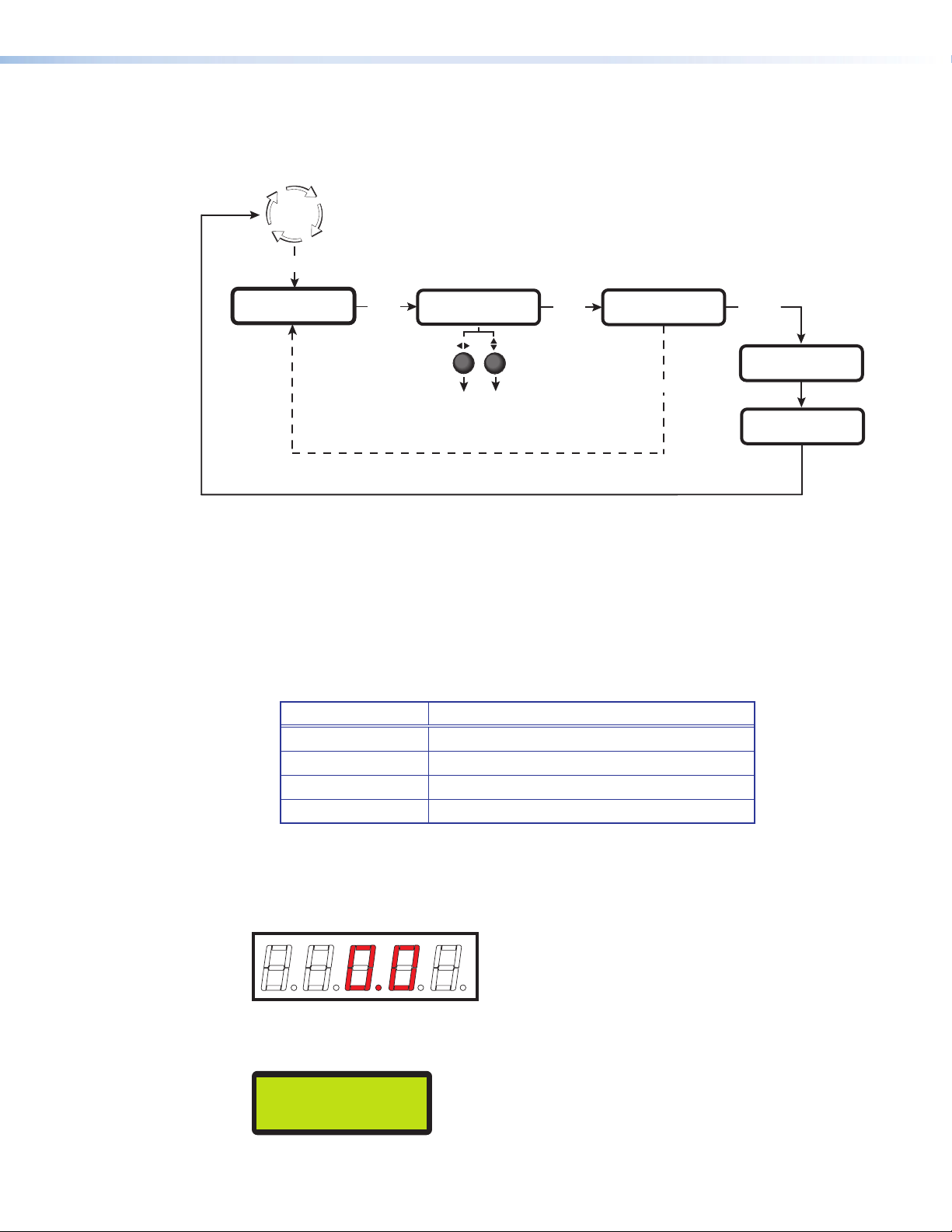
Channel Setup Menu
The Channel Setup menu lets you select the radio frequency source (over-the-air or cable)
and to scan for available channels.
Default
Cycle
Menu
CHANNEL
SETUP
Use either Adjustment knob
to select a submenu option.
Next
RF SOURCE
AIR
• AIR (Default)
• CABLE STANDARD
• CABLE HRC
• CABLE IRC
Next
PRESS UP BUTTON
TO START SCAN
Next
When the scan is complete, the name and
number of the first channel are displayed.
>
(Up)
SCANNING
KTLA-DT
1%
5-1
Figure 15. Channel Setup Menu Flow
Selecting the signal source
The AVT 200HD accepts signals over the air or via cable: standard, HRC, and IRC. To select
the signal source:
1. Press Menu until Channel Setup is displayed in the LCD screen.
2. Press Next once.
3. Turn either Adjustment knob in either direction until the desired source is displayed.
Option Scans for
Air (default) Over-the-air channels
Cable Standard
Cable HRC
Cable IRC
Clear QAM channels in standard cable format
Clear QAM channels in HRC cable format
Clear QAM channels in IRC cable format
Scanning for channels
The AVT 200HD can scan all cable or over-the-air channels and save to memory those with
an active signal.
If no channels have been detected and saved, the LED display shows the following:
Figure 16. LED Display with No Channels Scanned
The LCD screen displays the following:
[SOURCE] CHANNEL
LIST EMPTY
Figure 17. LCD Screen with No Channels Scanned
AVT 200HD Tuner • Operation 18
Page 25
Follow these steps to scan for channels from the front panel. The AVT must be in tune
CHANNEL
mode. If the desired signal source has already been selected, or if the channel scan is being
performed for the first time on this system, skip steps 1 through 3.
1. Place the AVT in tune mode (see “Selecting tune or preset mode,” later in this
section).
2. Select the signal source from the RF Source menu (see “Selecting the signal source,”
earlier in this section).
3. Press Next until the LCD screen displays Press Up button to start scan.
4. Press the Up (>) button.
CHANNEL
SDTV
EDTV
HDTV
NOTE: To stop a scan, press the Menu button. The LCD screen displays Scanning
Stopped for 2 seconds, then returns to the default cycle.
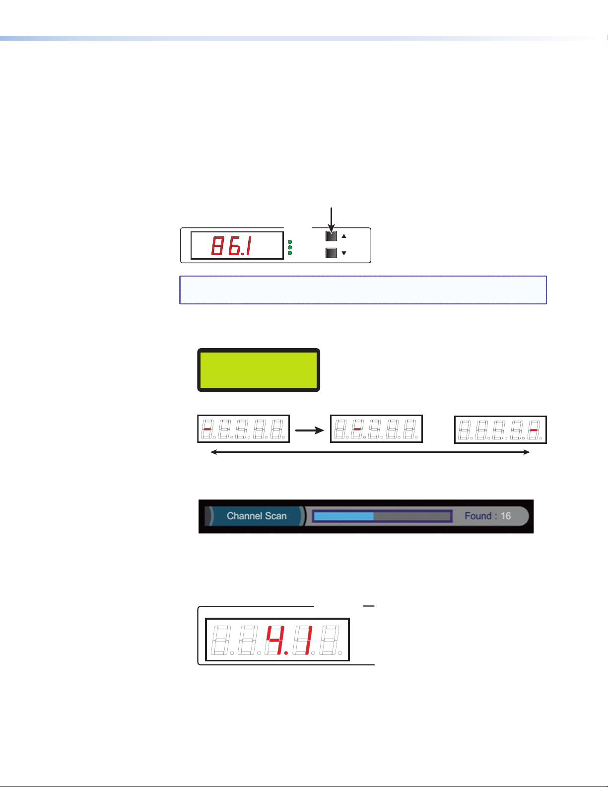
While the scan is in progress, the following takes place:
• The percentage complete is incremented on the LCD screen. For example:
SCANNING
21%
• On the LED display, a red dash moves back and forth through the digit positions:
...
• On the on-screen display, the status bar displays Channel Scan, a progress bar, and
the number of channels detected.
When the scan is complete:
• If channels are found and saved, the LCD screen displays the name and number
of the first (lowest-numbered) channel, then returns to the default cycle.
The first channel number also appears on the LED display. For example:
AVT 200HD Tuner • Operation 19
Page 26
• If no channels are found, the LCD screen displays [RF source]
CHANNEL LIST Empty, alternating with PRESS UP BUTTON to START SCAN.
[SOURCE] CHANNEL
LIST EMPTY
If you want to repeat the scan, press the > button.
To return to the Channel Setup menu, press the Menu button. (Following a failed
scan, the display does not automatically return to the default cycle.)
Channels with long minor numbers
Most cable channel numbers do not exceed 5 digits including both major (preceding the
decimal point) and minor (following the decimal point) numbers. However, some cable
channels that do not have virtual channel numbers assigned may have 3- or 5-digit minor
numbers, making those numbers too large to be displayed on the LED panel. For these
numbers, the LED display shows only the last two digits of the minor number, followed by
an additional dot.
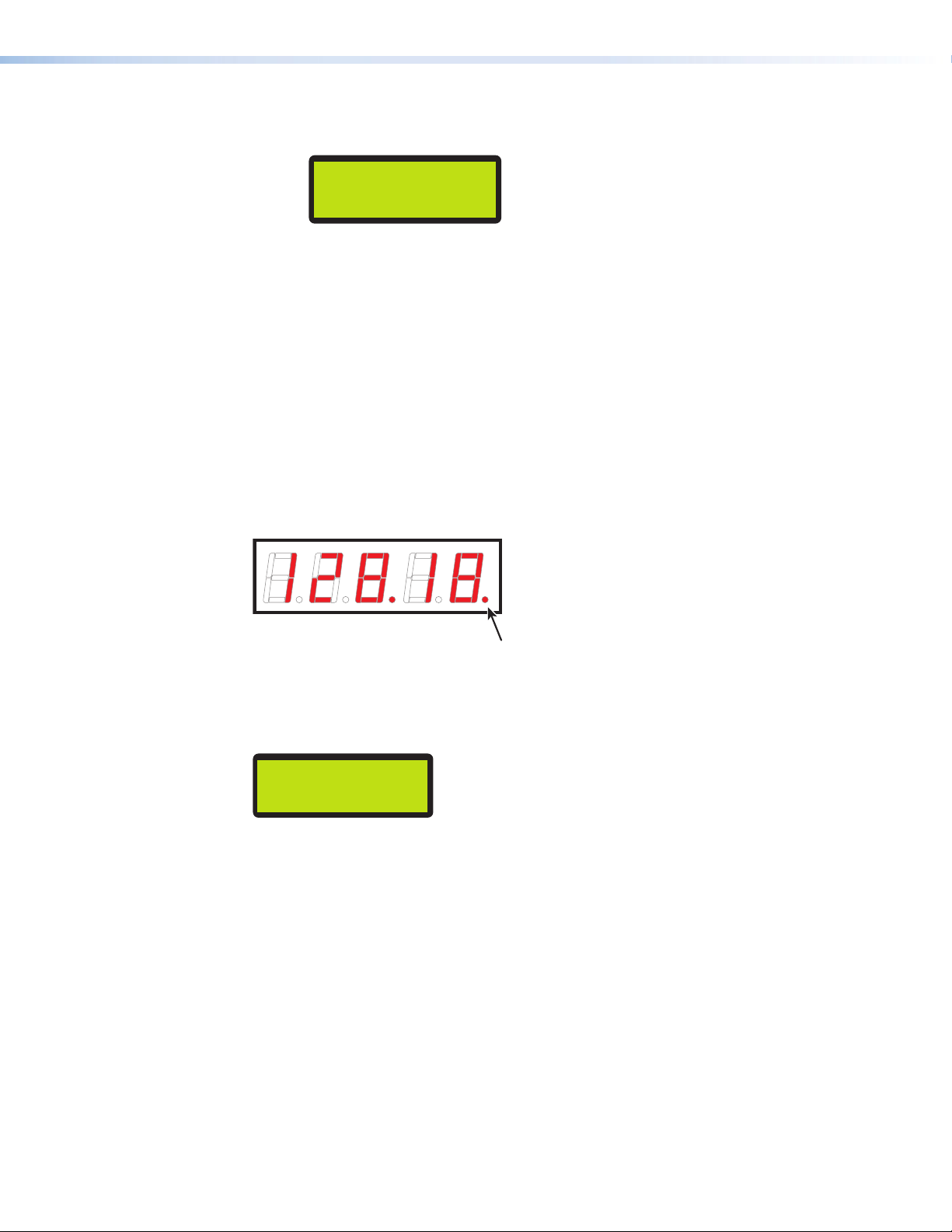
In the example below, the cable channel number is 128.25018. For this channel, the LED
display shows the major number (128) and only the last two digits of the minor number
(18). This number is followed by a red dot at the end, indicating that the displayed channel
number is a partial one.
Figure 18. Large Channel Number on LED Display
To find out the entire channel number, look at the LCD window, which always displays the
entire number (with a hyphen [-] in place of the decimal point). The number shown in the
figure above would appear on the LCD screen as:
CABLE 128-25018
Figure 19. Large Channel Number on LCD Screen
AVT 200HD Tuner • Operation 20
Page 27
Output Configuration Menu
From this menu, you can set output parameters, including resolution and refresh rate,
display aspect ratio, and closed captioning. This menu also enable you to select the
operating mode (tune or preset).
CHANNEL
SETUP
Menu
OUTPUT
CONFIGURATION
Use either Adjustment knob
to select a submenu option.
Next
CLOSED CAPTION
• OFF (default)
• SERVICE 1
• SERVICE 2
• SERVICE 3
• SERVICE 4
• SERVICE 5
• SERVICE 6
OFF
Next
Next Next
TUNER MODE
TUNE
• TUNE (default)
• PRESET
DISPLAY MODE
FOLLOW
• FILL
• FOLLOW (default)
• ZOOM
Next
RESOLUTION
1080i @ 60
• 480i @ 59.94
• 480p @ 59.94
• 720p @ 60
• 1080i @ 60 (default)
DISPLAY TYPE
X 9
16
• 16 x 9 (default)
• 4 x 3
Figure 20. Output Configuration Menu
The tasks accessed from the Output Configuration submenus include:
• Selecting tune or preset mode (Tuner Mode submenu)
• Selecting the output resolution and refresh rate (Resolution submenu)
• Selecting the display aspect ratio (Display Type submenu)
• Selecting the display mode (Display Mode submenu)
• Selecting the closed caption service (Closed Caption submenu)
Next
Selecting tune or preset mode
The AVT 200HD has two tuning modes: tune and preset. You can use the front panel
menus, the Windows-based control software, SIS commands, the embedded web pages, or
the AVT 200HD Remote Control to switch between modes.
• Tune mode: In tune mode, the Up (>) and Down (<) buttons increment and
decrement the channel number with each press of the button. If a button is held down
for 2 seconds, the channels tune rapidly up or down until the button is released. Tune
mode is the default.
In this mode, you can also do the following:
• Scan for available channels and save them to memory (see “Scanning for
channels,” earlier in this section).
• Save (associate a channel with) a preset. You can do this using SIS commands, the
AVT 200HD IR Remote Control, the HTML (web) pages, or the Windows-based
control software. You cannot save a preset from the front panel.
AVT 200HD Tuner • Operation 21
Page 28

• Preset mode: In preset mode, the Up and Down buttons step up or down through
presets that have been saved.
NOTE: Using the front panel, SIS commands, the Windows-based control software,
the HTML pages, or the IR Remote Control, you can recall presets in tune
mode and preset mode.
To switch between tune and preset modes:
1. From the Output Configuration menu, press Next repeatedly until the LCD screen
displays Tuner Mode.
2. Rotate either Adjustment knob to select Tune or Preset.
Selecting a channel
To tune to a channel, the AVT 200HD must be in tune mode.
You can tune using either of the following methods:
• Press the Up or Down button to tune to the desired channel. The current channel
number is displayed in the LED display and on one of the default cycle screens.
• Press and hold the Up or Down button to cycle rapidly through the channel numbers.
When the highest channel number available is reached, the display restarts numbering
at the lowest channel number.
If the AVT 200HD is in preset mode, you can tune only to a preset channel. To change
preset channels, press the Up or Down button to display the numbers of the programmed
presets in ascending or descending order in the LED and LCD displays.
If you rerun a channel scan and any different channels are found on the second scan, the
channel and preset lists are updated automatically to add new detected channels or remove
channels that are no longer available. (To scan for channels, the AVT must be in tune mode.)
If the signal for a channel becomes too weak to be detected, the video output screen
displays a “No Signal” message.
Saving presets (Not available via the front panel)
The AVT 200HD allows 198 programmable presets: 99 for over-the-air and 99 for cable. You
cannot save a preset using the front panel menu system; you can only recall one. You can
save a preset using the following methods:
• SIS commands (see the Presets commands in the Command/Response
Table for AVT 200HD SIS Commands, located in the “Remote Configuration
and Control” section)
• The AVT 200HD Remote Control (see “Using the AVT 200HD IR Remote
Control,” later in this section)
• The Tuner Settings web page (see “Saving a preset” in the “HTML
Configuration and Control” section)
• The Windows-based configuration and control software (see the program help)
Only channels that have been found by a channel scan can be saved as presets (see
“Scanning for channels,” earlier in this section).
When a preset is saved, the system gives it the default name “Presetnn,” where nn is the
preset number (for example, Preset01). You can change this name using the four methods
listed above. A preset can have up to 10 characters.
You can also overwrite a preset and save a different channel to its number by using one of
the four methods listed above.
AVT 200HD Tuner • Operation 22
Page 29
Recalling presets
When a channel is saved as a preset, you can tune to that channel by selecting its preset.
Using the front panel menus, you can recall a preset that has been saved.
When you select a preset, it recalls the cable or over-the-air TV channel that was
programmed for it.
NOTE: Channel presets that are programmed while the AVT is in either over-the-air or
CATV mode remain exclusive to the mode in which they were saved.
To recall (select and tune to) a preset channel from the front panel:
1. Place the AVT in preset mode.
2. Press the Up (>) or Down (<) button repeatedly until the desired preset number is
displayed on the LED panel.
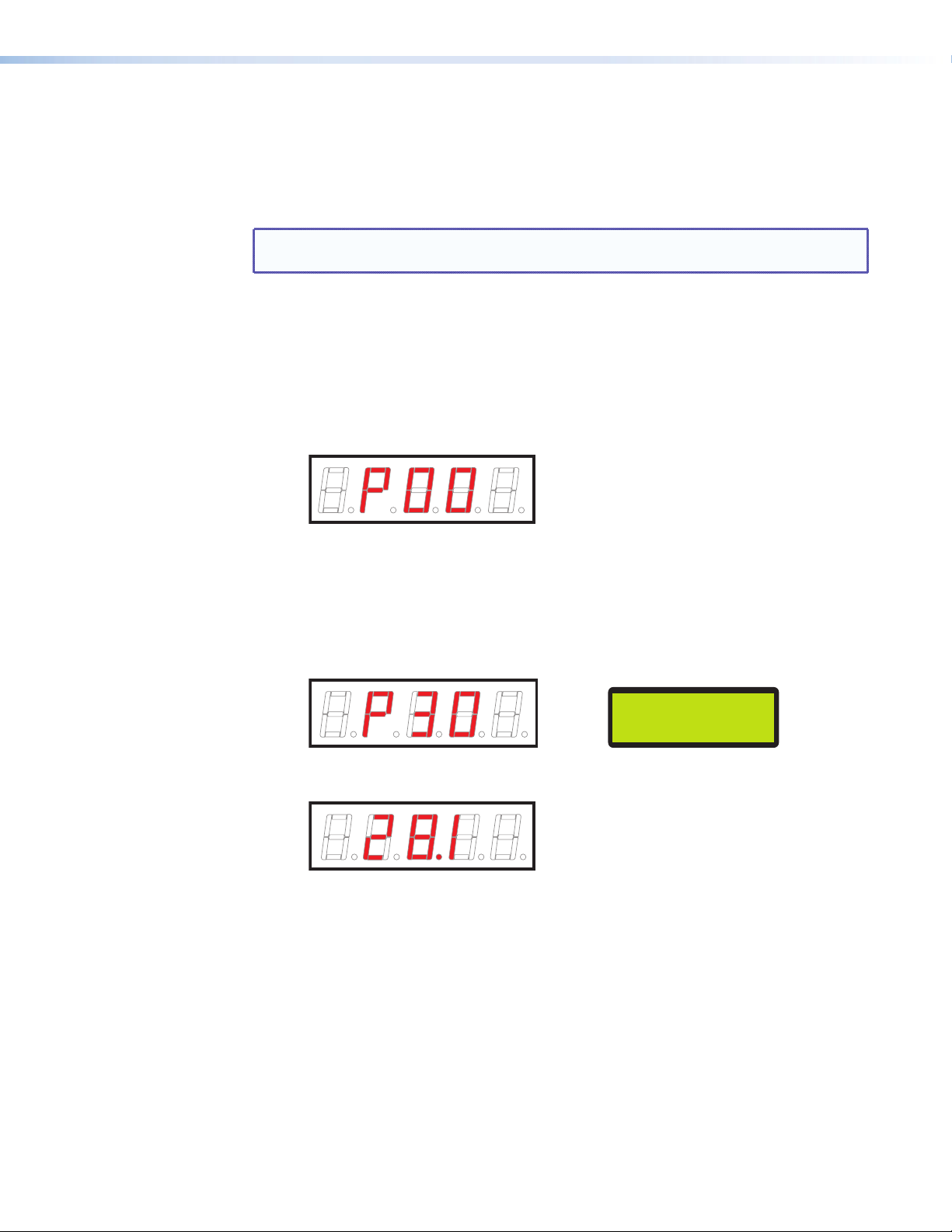
• If no presets have been saved, the LED display flashes “P 0 0” for 2 seconds,
then returns to the currently selected channel number (or to 0.0 if no channel scan
has been performed).
• If presets have been saved, the currently selected preset number is displayed
for 2 seconds, then the channel number associated with the selected preset is
displayed. The LCD screen displays the preset number (or name, if you defined one
using the control software or SIS commands), along with the channel name and
number.
Example: If preset 30 is selected via the Up or Down button in Preset mode, the
LED and LCD displays show the following:
PRESET30
AIR 28–1
After 2 seconds, the digital display shows the channel number (28.1 in this example)
associated with preset number 30.
In addition to the front panel buttons, you can use SIS commands (see the “Remote
Configuration and Control” section); the control software (see the AVT 200HD control
program help file); the AVT 200HD web pages (see “HTML Configuration and Control”),
or the IR remote control buttons (see “Using the AVT 200HD IR Remote Control,” later in
this section) to recall presets.
Selecting the output resolution and refresh rate
The following table shows the available resolutions for each video output type. The refresh
rate is fixed for each resolution. Multiple output devices can be connected to the AVT if their
resolutions are the same. Output sync polarity can be changed by an SIS command (see the
Set output polarity command in the “Remote Configuration and Control” section) or via
the control software (see the control program help file).
AVT 200HD Tuner • Operation 23
Page 30

Simultaneous Video Output
Resolution
480i @ 59.94 Hz X X X X
480p @ 59.94 Hz X X X*
720p @ 60 Hz X X X
1080i @ 60 Hz (default) X X X
*480p HDMI output has a 54 MHz pixel clock. Check with the manufacturer of your display to find out if
it supports this rate.
To select the output resolution:
1. From the Output Configuration menu, press Next until the LCD screen displays the
Resolution submenu screen. Example:
Composite S-video Component RGBHV
(with embedded audio)
HDMI
RESOLUTION
1080i @ 60
2. Rotate either Adjustment knob in either direction until the desired resolution is
displayed.
NOTE: Each new selection can take up to 20 seconds to be applied.
Selecting the display aspect ratio
The Display Type submenu lets you select the aspect ratio of the output monitor. The
available selections are 16x9 (the default) and 4x3. From the Display Type submenu, rotate
either Adjustment knob until the desired aspect ratio is displayed.
Selecting the display mode
The Display Mode submenu lets you select the appearance of the image on the display
screen. The options are:
• FILL — The image fills a 16x9 screen. If the video image is 4x3, it is stretched
horizontally to fit the larger screen.
• FOLLOW (default) — The aspect ratio of the output image follows that of the source (also
called “normal” mode).
A 4x3 video image is framed to a 16x9 display area, retaining its original aspect ratio but
with vertical black bars on both sides of the screen. A 16x9 image is framed to a 4x3
area, with its original aspect ratio but with horizontal black bars at the top and bottom
of the screen.
• ZOOM — The image is evenly stretched both horizontally and vertically, until the picture
fills the entire width of the screen.
The figure on the next page shows how the display appears in each mode for the two
display formats.
AVT 200HD Tuner • Operation 24
Page 31

Figure 21. Display Modes for 4x3 and 16x9 Monitors
Selecting the closed caption service
The Caption submenu lets you enable closed captioning and select a service. The options are
Off (the default) or Service 1 through Service 6. Primary captioning service is provided
on Service 1 and secondary service, on Service 2. Services 3 through 6 can be used for
additional closed captioning if it is available.
Audio Configuration Menu
This menu enables you to select the digital audio output type and to specify the language
for a second audio program if the channel supports it.
OUTPUT
CONFIGURATION
Menu
AUDIO
CONFIGURATION
Next
DIGITAL OUT
• AC-3 (Default)
• PCM
Figure 22. Audio Configuration Menu
AC-3
Tu rn either Adjustment
knob to select a setting.
Next
LANGUAGE
ENGLISH
• ENGLISH (Default)
• SPANISH
• FRENCH
Next
AVT 200HD Tuner • Operation 25
Page 32

The following functions are available via the Audio Configuration submenus:
• Selecting the digital audio type (Digital Out submenu) — Select the type of digital
audio output. The options are AC-3 (Dolby digital surround, the default) or PCM
(standard digital audio).
• Selecting a second language (Language submenu) — Select the language for a
second audio program (SAP), such as a second language or descriptive video service
(DVS), if the channel supports it.
Comm Setting Menus
Use the View Comm Setting and the Edit Comm Setting menus to view and edit the serial
communication port configuration and the IP addresses.
CONFIGURATION
VIEW COMM
SETTINGS
AUDIO
Menu
Next
Menu
EDIT COMM
SETTINGS
Next
REMOTE PORT
RS-232 9600
Next
MAC ADDRESS
0005A605623D
196.168.254.254
255.255.000.000
Next
GATEWAY ADDRESS
000.000.000.000
Next
DHCP MODE
<OFF> ON
Next
IP ADDRESS
Next
SUBNET MASK
Next
Menu
Next + [
+
>
Press and hold
for 2 seconds.
<
]
Figure 23. Comm Setting Menu Flow
REMOTE PORT
RS-232 9600
Next
DHCP MODE
<OFF> ON
Next
IP ADDRESS
196.168.254.254
Next
SUBNET MASK
255.255.000.000
Next
Rotate the horizontal or vertical
Adjustment knob to select a setting.
Next
GATEWAY ADDRESS
000.000.000.000
Menu
AVT 200HD Tuner • Operation 26
Page 33

Viewing serial port and IP settings
The View Comm Setting menu appears after the Audio Configuration menu as you press
the Menu button to cycle through the menus. All the View Comm Setting screens that you
cycle through by pressing Next show the current settings. You cannot make changes from
these screens.
To view the current port settings:
1. Press Menu repeatedly until the View Comm Setting menu is displayed on the LCD
screen.
2. Press Next repeatedly to cycle through the screens displaying the current settings for
the serial port baud rate, MAC address, DHCP mode, IP address, gateway address, and
subnet mask.
3. Press Menu to return to the View Comm Setting screen.
Configuring the serial port and IP parameters
To make changes to the serial port configuration, IP address, DHCP mode, gateway address,
or subnet mask, access the edit level screens as follows:
1. With any View Comm Setting menu screen displayed, press and hold the Next
button and, while holding the Next button, press the Up (>) and Down (<) buttons
simultaneously until the Edit Comm Setting menu appears (approximately 2 seconds).
2. Press Next repeatedly to cycle through the Edit Comm Setting screens. When a new
screen is displayed, the currently selected item either blinks or is surrounded by angle
brackets (< >).
3. To enter or change information on each screen, rotate the horizontal Adjustment knob
([) to move the blinking or the angle brackets to the desired setting. Rotate the
vertical Adjustment knob ({) to change the setting.
4. When finished editing the settings for the selected item, do one of the following:
• Press Next to go to the next editing screen.
• Press Menu once to return to the Edit Comm Setting menu.
• Press Menu twice to exit editing mode and go to the View Comm Setting menu.
The following screens can be edited:
• Remote Control RS-232: Select the baud rate. The available rates are 9600 (the
default), 19200, 38400, and 115200.
• DHCP Mode: Set DHCP (Dynamic Host Configuration Protocol) to On or Off. When
DHCP is on, the AVT obtains its IP address from the local network; you do not set the
address.
NOTE: DHCP must be off before you can edit the IP, subnet, and gateway
addresses. If DHCP is on, the three address screens are not displayed.
• Addresses: To change these addresses, rotate the horizontal Adjustment knob to select
one of the octets and the vertical Adjustment knob to increment or decrement the
selected number (0 through 255).
• IP Address: Set the IP address. The default address is 196.168.254.254.
• Subnet Mask: Set the subnet mask address. The default is 255.255.000.000.
• Gateway Address: Set the gateway address. The default is 000.000.000.000.
NOTE: These address screens do not appear in the Edit menu if DHCP is on.
AVT 200HD Tuner • Operation 27
Page 34

Unit Reset Menu (Resetting from the Front Panel)
Three modes of reset can be initiated from the AVT 200HD front panel.
VIEW
COMM SETTING
Menu
Default
Cycle
UNIT
RESET
Next
Menu
FACTORY
RESET
Tu rn either Adjustment knob
to select a reset mode.
• FACTORY RESET
• RESET USER SETTINGS
• CLEAR CH & PRESET LIST
RESETTING UNIT
PLEASE WAIT..
Next
PRESS NEXT
TO RESET
Next
Figure 24. Unit Reset Menu Flow
To reset the unit using the front panel menus:
1. Press the Menu button repeatedly until Unit Reset is displayed on the LCD screen.
2. Press Next to go to the Unit Reset submenu.
3. Rotate either Adjustment knob to display the reset options:
• Factory Reset: Restores all settings to the defaults that were set at the
factory except the IP settings. (This selection is equivalent to the SIS command
E
ZXXX; see the Total reset command in the “Command/response Table for SIS
Commands,” “Remote Configuration and Control” section.)
• Reset User Settings: Resets all settings except the scanned channels and presets.
• Clear Ch & Preset List: Erases scanned channels and presets.
4. When the desired reset option is displayed on the LCD screen, press Next. The LCD
screen displays Press Next to Reset.
5. Press Next to start the reset. While the unit is being reset, the LCD screen displays
Resetting Unit Please Wait.
When the reset is complete, the LCD display returns to the default cycle if the channel
list has not been removed. If the channel list has been deleted, the [Source] Channel
List Empty and Press Up Button to Start Scan messages alternate on the LCD
screen.
NOTE: You can perform resets using:
• The Reset button (see “Resetting from the Rear Panel,” later in this
section)
• SIS commands (see the Resets commands in the “Remote Configuration
and Control” section)
• The Windows-based control software (see the program help file)
AVT 200HD Tuner • Operation 28
Page 35

Exiting the Menu System
To exit the menu system and return to the default cycle, do either of the following:
• Press the Menu button repeatedly until Press Next to Exit is displayed on the LCD
screen, then press Next.
• Do not press any button. After approximately 30 seconds, the default cycle starts on the
LCD screen.
Volume Control
Rotating the Volume knob on the front panel increases and decreases the audio volume
in up to 100 steps. When this knob is turned, the LCD window displays a bar graph
representation of the volume level for 0.3 seconds before returning to the previous menu. In
addition, the volume percentage is displayed in the upper-right corner of the LCD screen.
VOLUME 22%
Figure 25. Example of the LCD Screen during Volume Adjustment
Volume adjustment can be made from the front panel at any time during tuner operation.
Resetting from the Rear Panel
The rear panel contains a recessed Reset button that initiates four levels of resets. To select
a reset level, use a pointed object such as a small Phillips screwdriver to press and hold the
button while the tuner is running (modes 2 through 4) or while you are applying power to it
(mode 1). The adjacent Reset LED provides feedback on the current reset mode.
The table on the next page provides a summary of the four reset modes.
CAUTION: Review the reset modes carefully. Using the wrong reset mode could result
in unintended loss of flash memory programming, port reassignment, or a
tuner reboot.
NOTES: • The reset modes are separate functions, not a continuation from mode 1 to
mode 5.
• There is no reset mode 2 for the AVT 200HD.
AVT 200HD Tuner • Operation 29
Page 36

Reset Modes Summary
Mode Activation Result Purpose/Notes
1 Hold in the Reset button while
applying power to the tuner.
Restores the factory-installed firmware.
All user settings and files, such as audio
adjustments and IP settings, are retained.
Event scripts do not run when the tuner
is powered on in this mode.
Mode 1 can be
used to remove a
version of firmware
if compatibility issues
arise.
3 Hold in the Reset button until
the Reset LED blinks once (after
approximately 3 seconds); then within
1 second press Reset momentarily
(for less than 1 second).
4 Hold in the Reset button until the
Reset LED blinks twice (once after
approximately 3 seconds and again
after 6 seconds); then within 1 second
press Reset momentarily (for less than
1 second).
5 Hold in the Reset button until the
Reset LED blinks three times (once
after approximately 3 seconds, again
after 6 seconds, and then again after
9 seconds); then within 1 second
press Reset momentarily (for less than
1 second).
Turns events on and off. During
resetting, the Reset LED flashes two
times if events are starting or three times
if events are stopping.
• Enables ARP capability.
• Sets the IP address, subnet address,
and gateway address to the factory
defaults.
• Sets port mapping to the factory
default.
• Turns DHCP off.
• Turns events off.
The Reset LED flashes four times in quick
succession during the reset.
Performs a complete reset to factory
defaults (except the firmware):
• Does everything mode 4 does.
• Resets almost all real time
adjustments:
• Clears the channel list, all presets,
and audio settings.
• Resets all IP options.
• Clears all files from the tuner.
The Reset LED flashes four times in quick
succession during the reset.
Mode 3 is useful for
troubleshooting.
Mode 4 enables you
to set IP address
information using the
ARP command and
the MAC address.
It does not replace
any user-installed
firmware.
Mode 5 is useful if
you want to start over
with configuration
and uploading and
also to replace events.
AVT 200HD Tuner • Operation 30
Page 37

Locking and Unlocking the Front Panel (Executive Modes)
To prevent access by unauthorized users or accidental changes to the AVT 200HD settings,
you can lock most of the front panel controls by using executive modes. (The rear panel
RS-232 and LAN ports and the front panel USB Config port remain accessible in all executive
modes).
You can also select executive modes via the serial or LAN ports by using the SIS commands
(see the executive mode commands in the “Remote Configuration and Control” section),
the Windows-based control software (see the program help file) or the web pages (see
“Tuner Settings Page“ in the “HTML Configuration and Control” section).
The AVT 200HD has four types of security lock that set limits for operation of the tuner from
the front panel:
• Disable mode (default) — The front panel is completely unlocked (executive mode is
disabled). All front panel functions are available.
To unlock the front panel, press the Menu and Next buttons simultaneously and hold
them until the following message is displayed on the LCD screen (approximately
2 seconds):
EXEC MODE SELECT
DISABLE
• Complete mode — All functions are locked from the front panel except for disabling
executive mode. SIS commands, the configuration and control software, the HTML
pages, and the IR remote control remain available.
Any attempt to enter a command from the front panel results in the following message
displayed on the LCD screen for 2 seconds:
EXECUTIVE MODE
COMPLETE
• Volume only mode — Locks all front panel operations except volume adjustments.
Any attempt to enter a command from the front panel results in the following message
displayed in the LCD screen for 2 seconds:
EXECUTIVE MODE
VOLUME ONLY
• IR Lockout mode — Locks out all IR access. The AVT IR remote control does not
communicate with the tuner when the AVT is in this mode. All other front panel
functions are available.
Any attempt to enter a command from the front panel results in the following message
displayed in the LCD screen for 2 seconds:
EXECUTIVE MODE
IR LOCKOUT
AVT 200HD Tuner • Operation 31
Page 38

You can access the Exec Mode Select menu when any other menu or submenu is displayed.
To select an executive mode:
1. Press the Menu and Next buttons simultaneously and hold them until the LCD window
displays the Exec Mode Select menu with the name of the current executive mode
(approximately 3 seconds).
2. Rotate either Adjustment knob until the desired mode name appears in the LCD
window.
3. Press the Menu or Next button to return to the default cycle or wait for the LCD display
to time out.
Menu
Default
Cycle
EXEC MODE SELECT
or
Menu + Next
DISABLE
• DISABLE (Default)
• COMPLETE
• VOLUME ONLY
• IR LOCKOUT
[ANY MENU]
Use either Adjustment knob
to select an executive mode.
Figure 26. Executive Mode Menu Flow
Using the AVT 200HD IR Remote Control
The optional hand-held AVT 200HD IR Remote Control lets you remotely perform many
of the functions that are also available through the front panel, SIS commands, the
Windows-based control software, or the embedded web pages. The AVT responds to
commands from the remote control as if the corresponding front panel button were pressed
or the corresponding SIS command or software selection were entered.
From a distance of no more than 30 feet (9.1 m), the remote control sends infrared (IR)
signals to the AVT 200HD through the infrared remote sensor, located on the front panel
to the left of the LED channel display. The IR sensor can receive the signal if it is sent from
within a 40 degree arc to the right or left of direct line of sight between the remote control
and the AVT receiver. See the diagram on the next page.
AVT 200HD Tuner • Operation 32
Page 39

IR
CONFIG
SDTV
EDTV
HDTV
AVT 200HD
40 40
CHANNEL
30’ (9.1 m)
maximum
MUTE
AUDIO
VIDEO
TUNE
VOLUMECHANNEL
PRESET
CHANNEL SELECTION
321
CC
4
5 6
7 809
SAVE
ENTER
LAST
SHIFT
INFO
GUIDE
FREEZE
AVT 200HD Remote
AVT 200HD Remote Control
Figure 27. Area for Remote Signal Reception
NOTES: • The AVT must be connected to power before you operate the remote control.
• Setup operations cannot be performed from the remote control.
Installing batteries in the AVT 100 Remote
Install two AAA batteries in the AVT 200HD Remote Control as shown below.
Figure 28. Installing Batteries in the AVT 200HD IR Remote Control
AVT 200HD Tuner • Operation 33
Page 40

Buttons on the AVT 200HD Remote Control
The following functions are available through the buttons on the AVT 200HD IR Remote
Control:
1
MUTE
14
13
12
11
10
VIDEO
CHANNEL SELECTION
4
7 809
LAST
INFO
9
TUNE
PRESET
5 6
GUIDE
AVT 200HD Remote
SHIFT
AUDIO
VOLUMECHANNEL
2
3
321
CC
4
SAVE
ENTER
5
6
FREEZE
7
8
Figure 29. Buttons on the AVT 200 Remote Control
a Video and Audio Mute buttons — Toggle video and audio output muting on and off.
• When the channel is changed, the video is unmuted.
• When the volume is adjusted, the audio is unmuted.
b Preset — Puts the AVT in preset mode. In preset mode, the Channel Selection buttons
(b) switch between preset channels.
c Volume — Press the top (up arrow) or bottom (down arrow) section of this rocker
button to raise or lower the output volume.
d CC — Selects a closed captioning service (CC1 through CC6) or turns it off.
e Save — In tune mode, saves the currently selected channel as a preset. (Presets cannot
be saved while the AVT is in preset mode.)
f Enter — After using the numbered selection buttons (
number, press this button to switch to that channel or preset.
g Shift buttons — After the Guide button (
• The up and down arrow buttons step through the program menu on the on-
screen display.
• The left arrow button lets you back-space and delete numbers that you entered
on the LED panel by pressing the channel selection buttons (l). This button does
not delete numbers after you press the Enter button to confirm your selections.
• The right arrow button is reserved for future use.
) is pressed:
i
) to select a channel or preset
l
h Freeze — Freezes and unfreezes the video output.
AVT 200HD Tuner • Operation 34
Page 41

i Guide — Toggles the on-screen Program Guide (list of programs currently available on
the selected channel) on and off.
j Info — Turns on the on-screen display with information on the current channel. (This
button does not turn the display off; after approximately 3 seconds, the OSD turns off
automatically.)
k Last — Tunes to the previous channel.
l Channel Selection buttons (0 through 9) —
• In tune mode, press these numbered buttons to specify a channel number.
• In preset mode, press these buttons to specify a preset number.
After selecting a channel or preset number, press Enter (f) to confirm your selection.
m Channel — Press the up and down arrows on this rocker button to increment or
decrement the channel number (in tune mode) or the preset number (in preset mode).
Pressing and holding this button causes the AVT to cycle rapidly through the channels or
presets until the button is released.
• In tune mode, pressing either part of this button displays the adjacent channel
number. If a channel scan has been performed, pressing the Channel button causes
the display to cycle through the channels that were set by the scan for the signal
source (over-the-air or cable) in which the scan was done. In this case, the adjacent
channel may not be available for display.
• In preset mode, the next or previous preset channel is displayed, depending on
which part of the button you pressed. The LED panel briefly displays the preset
number preceded by a “P,” then it displays the channel number associated with that
preset.
If no presets have been defined when the Channel button is pressed, the LED display
shows “P00,” then the channel number to which the AVT was set before entering
preset mode.
NOTE: The Channel button applies to both ATSC and cable modes. See
“Selecting the signal source,” earlier in this section, to switch between
these sources.
n Tune — Press this button to switch to tune mode. In tune mode, the Channel buttons
switch between channel numbers.
Selecting a Channel or Preset Using the IR Remote Control
To select or change a channel or preset using the AVT 200HD IR Remote Control:
1. Using the channel selection number buttons, enter each digit of the desired channel or
preset number. For channel selection, use the hyphen (–) button to indicate the decimal
point separating the minor numbers from the major numbers.
Example: To select channel 53.4, press the buttons numbered 5, then 3, then –,
then 4.
The front panel LED display shows the following:
• In tune mode: The channel numbers you pressed, aligned with the left edge of the
field
• In preset mode: The letter P followed by the preset number you pressed, aligned
with the left edge of the field (see the example on the next page).
AVT 200HD Tuner • Operation 35
Page 42

2. Press the Enter button to implement the channel or preset selection.
• If the number you entered is a valid channel or an existing preset number, the AVT
switches to it, and the number is displayed on the LED panel, aligned with the right
position in the field (shown in the example below).
The default cycle on the LCD screen displays the new channel number with a
hyphen instead of a decimal point (shown in the example below).
KRZY–DT
AIR 28–1
• If you enter an invalid channel or preset number, the LED display blinks three times,
then returns to the channel number that was displayed previously (the display on
the LCD does not change). The channel or preset is not changed.
Locking IR Remote Control Access
The AVT 200HD Remote Control can be set to lock out users from using it to control the
AVT. This is done by selecting the IR LOCKOUT from the front panel Exec Mode Select
menu (see “Locking and Unlocking the Front Panel (Executive Modes),” earlier
in this section); SIS commands (see the executive mode commands in the “Remote
Configuration and Control” section); the web pages (see “Tuner Settings Page“ in the
“HTML Configuration and Control” section); or the Windows-based control software (see
the program help file). When remote control is locked, all other AVT 200HD controls remain
available (SIS commands, the web pages, the control software, and the front panel).
Using the On-screen Display (OSD)
The AVT 200HD provides a translucent on-screen display (OSD) on which you can view
program information for the current channel or the volume level.
NOTE: The OSD screens are for viewing only. You cannot make selections from them.
Introductory Display
Whenever you change a channel, a translucent display pops up on the television screen,
showing the following information:
• Channel number
• Channel name
• Program title
• Time of day
• Signal strength
This same display appears when you power on the AVT if it is connected to a display that
is already powered on. You cannot disable this introductory display. After approximately
5 seconds, the display disappears.
AVT 200HD Tuner • Operation 36
Page 43

In the example on below, the current channel is 4.1 (on the OSD, the decimal point is shown
as a hyphen); the channel name is NBC–4LA; the title of the program currently running is
“Today”; the time is 1:37 pm; and the signal strength (shown by a vertical bar graph above
the time) is medium.
Figure 30. Introductory Channel Display Example
Channel Information Display
The channel information display is a translucent window similar to the introductory channel
display. It contains all the information that is in the introductory display plus the channel
resolution, the language in which the current program is being broadcast, the program
rating (G, TV-PG, TV-14, and so on), and whether or not closed captioning is on.
You can enable the OSD displays using the IR remote control (see the ”j Info“ button
description under “Buttons on the AVT 200HD IR Remote Control,” earlier in this section),
the configuration and control software (see the program help file), or SIS commands (see
the “On-screen display (OSD)” commands in the “Remote Configuration and Control”
section). The channel information is displayed for approximately 3 seconds, then the window
closes.
In the following example (read left to right), the current channel is 5.1; the channel name
is KTLA-DT; the broadcast resolution is 1080i; the signal strength is medium, the program
being broadcast is “Jerry Springer”; the time is 1:45 pm; the program is in English; closed
captioning (CC) is enabled, and the program rating is TV-14.
Figure 31. Channel Information Display Example
Volume Level Display
Whenever the volume is adjusted by any method, the volume level display is shown on the
screen for approximately 3 seconds.
Figure 32. Volume Level Display on the OSD
Unlike the volume display on the LCD screen, this on-screen display shows the volume
increase or decrease in increments of 5% (20 steps). (Volume adjustments that are made
using the front panel knob, the communication and control software, or SIS commands are
displayed in the LCD window and on the computer screen in 1% increments [100 steps].)
VOLUME 22%
Figure 33. Volume Display on the LCD Screen
AVT 200HD Tuner • Operation 37
Page 44

Program Guide
The translucent program guide display provides a list of the programs available on the
current channel for the day.
Figure 34. Program Guide Example
• To display the program guide, do any of the following:
• Press the Guide button on the IR remote control.
• Click the Prog Guide ON button on the Control tab of the Configuration &
Control Program. The button turns green when the Program Guide is enabled.
• Click the Program Guide On button on the Control tab, User Control web page.
• Enter the
E
1TVPG SIS command.
• To select a program using the program guide, press the up and down Shift arrow
buttons on the remote control to move the highlighting through the program list. When
a program is highlighted, the name, time period, and a brief description of the program
are displayed to the left of the program list. You can also enter SIS commands to move
the highlighting up (
E
+TVPG) or down (E–TVPG) through the program list.
• To close the program guide, do one of the following:
• Press the Guide button on the remote control again.
• Click the Prog Guide ON button again to remove the green highlighting (control
software).
• Click the Program Guide Off button on the User Control web page.
• Enter the SIS command
E
0TVPG.
NOTE: When you adjust the volume or change the channel (using any method), the
Program Guide closes.
AVT 200HD Tuner • Operation 38
Page 45

Remote Configuration and Control
This section describes the serial, Ethernet, and USB connections through which the Extron
Simple Instruction Set (SIS) commands can be issued, and lists the commands that are
available for configuring and controlling the AVT 200HD. Topics include:
• Serial Port
• USB Port
• Ethernet Port
• Using SIS Commands
• Accessing the AVT 200HD Control Software
Serial Port
USB Port
Ethernet Port
The AVT supports RS-232 serial communication protocol and can operate at 9600, 19200,
38400, or 115200 baud rates (see “Configuring the serial port and IP parameters” in
the “Operation” section to configure this port using the front panel menus).
The 5-pole shared 3.5 mm captive screw connector labeled RS-232/IR on the rear panel can
be connected to the serial port of a host device such as a computer running a utility such as
the Extron DataViewer or HyperTerminal, an RS-232 capable PDA, or a control system (see
“Wiring for RS-232 Control” in the “Installation” section for information on connecting to
this port).
SIS commands can also be sent through the USB Config port on the AVT front panel, using
Extron DataViewer or another utility that accommodates USB. (see “Connecting to the
USB Port” in the “Installation” section to set up communication via USB).
The RJ-45 connector on the rear panel can be connected to an Ethernet LAN or WAN to
enable SIS control of the AVT. The tuner and the controlling device can communicate via
Extron DataViewer or Telnet (a TCP socket using port 23). The Telnet port number can be
changed, if necessary, via SIS commands (see “Connecting as a Telnet Client” in the
“Reference Information” section for information on connecting via Telnet).
Ethernet Cable
The Ethernet cable must be properly terminated for your application as either a straight-
through cable or a crossover cable (see “Ethernet Connection” in the “Installation”
section for pin assignments for these cables).
AVT 200HD Tuner • Remote Configuration and Control 39
Page 46

IP Address
To access the AVT 200HD via the Ethernet port, obtain the IP address of the tuner from your
network administrator. If the IP address has been changed to an address comprised of words
and characters, you can determine the actual numeric IP address using the ping (ICMP) utility
(see “IP Addressing” in the “Reference Information” section for more information). If the
IP address has not been changed, the factory-specified default is 192.168.254.254.
Establishing an Ethernet Connection
Establish a network connection to a AVT 200HD as follows:
1. Open a TCP connection to port 23, using the IP address of the tuner. (A variety of
methods are available for making this connection, including Telnet and utilities such as
Extron DataViewer and HyperTerminal).
The tuner responds with a copyright message that includes the date, the name of the
product, firmware version, part number, and the current date and time.
NOTE: If the tuner is not password-protected, the device is ready to accept SIS
commands immediately after it sends the copyright message.
If the tuner is password-protected, a password prompt appears below the
copyright message.
2. If the tuner is password protected, enter the appropriate administrator or user password.
3. If the password is accepted, the tuner responds with Login User or Login
Administrator.
If the password is not accepted, the Password prompt reappears.
Connection Timeouts
The Ethernet link times out after a designated period of no communications. By default, this
timeout value is set to 5 minutes; however, the value can be changed (see the Set current
connection port timeout command in the Command/Response Table for IP-Specific SIS
Commands, later in this section).
NOTE: Extron recommends leaving the default timeout at 5 minutes and periodically
issuing the Query (Q) command to keep the connection active. If there are
long idle periods, Extron recommends disconnecting and reopening the
connection when another command must be sent.
AVT 200HD Tuner • Remote Configuration and Control 40
Page 47

Using SIS Commands
SIS commands consist of one or more characters per command field. They do not require
any special characters to begin or end the command character sequence. Each tuner
response to an SIS command ends with a carriage return and a line feed (CR/LF = ]), which
signals the end of the response character string. A string is one or more characters.
Tuner-initiated Messages
When a local event such as a front panel operation occurs, the tuner responds by sending a
message to the host. The tuner-initiated messages are listed below (underlined).
• Copyright message
With an RS-232 connection:
(c) Copyright 2011, Extron Electronics AVT 200HD, Vx.xx, 60-770-01
With an Ethernet connection:
(c) Copyright 2011, Extron Electronics, AVT 200HD, Vx.xx, 60-770-01
Ddd, DD Mmm YYYY HH:MM:SS
The tuner initiates the copyright message when it is first powered on or when an IP
is established. Vx.xx is the firmware version number. With the Ethernet connection, a
carriage return and the date and time are added to the copyright message.
This message is not displayed with a USB connection.
]
•
Password:
The tuner initiates the password message immediately after the copyright message
when the controlling system is connected using TCP/IP or Telnet and the tuner is
password protected. This message means that the tuner requires an administrator or
user level password before it will respond to the commands entered via this link.
The unit responds with one of the following messages, depending on the password that
was entered:
]
•
Login Administrator
]
Login User
The tuner initiates the login message when a correct administrator or user password has
been entered. If the user and administrator passwords are the same, the tuner defaults
to administrator privileges.
]
]
]
]
]
NOTE: The Password prompt is redisplayed if an incorrect password is entered.
TunerReady
After a unit reset or an output resolution change, the tuner sends this message to
indicate the reset is complete.
]
V-chip Security for Parental Control
In addition to passwords for administrators and users, a V-chip personal identification
number (PIN) is required to access and view parental control settings. With this PIN, you can
view and change these settings when logged in at either the administrator or user level. You
can set or change this password using SIS commands.
AVT 200HD Tuner • Remote Configuration and Control 41
Page 48

Tuner Error Responses
Space
If the AVT is unable to perform an SIS command that it receives because the command
is invalid or contains invalid parameters, the tuner returns an error response to the host.
Response include:
E01 — Invalid input number (too large)
E10 — Invalid command
E11 — Invalid preset number
E12 — Invalid port number
E13 — Invalid value (out of range)
E14 — Command not available for this configuration
E17 — System timed out
E22 — Busy
E24 — Privilege violation
E25 — Device not present
E26 — Maximum number of connections exceeded
E27 — Invalid event number
E28 — Bad filename or file not found
E30 — Hardware failure (followed by a colon [:] and a descriptor number)
E31 — Attempt to break port pass-through when it has not been set
E32 — Incorrect V-chip password
NOTE: User privileges extend to all view and read commands except reading the
administrator password. Users can also perform the following functions:
• Recalling presets
• Muting outputs
• Viewing V-chip settings (must enter the V-chip PIN)
Error Response References
14
= Commands that give an E14 (invalid command for this configuration) error if sent to a
product whose current configuration does not support the command
24
= Commands that give an E24 (privilege violation) error if you are not logged on at
administrator level
27
= Commands that may give an E27 (invalid event number) error
28
= Commands that may give an E28 (file not found) error
Using the Command/Response Tables for SIS Commands
The command/response tables begin on page 45. Upper- and lowercase letters are
acceptable in the command field except where indicated. The table below shows the
hexadecimal equivalent of each ASCII character used in the command/response table.
ASCII to Hex Conversion Table
•
Figure 35. ASCII to Hexadecimal Conversion
AVT 200HD Tuner • Remote Configuration and Control 42
Page 49

Special Characters
The following characters are invalid preset names, the tuner name, passwords, or locally
created file names:
~ @ = ` [ ] { } < > ’ ‘ “ ” ; (semicolon) : (colon) | / \ ? and space.
Symbol Definitions for AVT 200HD Specific Commands
]
= Carriage return with line feed
}
= Carriage return with no line feed
• = Space
| = Pipe (vertical bar) character. For URL-encoded commands, has the same function as ].
E
= Escape key
W = For URL-encoded commands, has the same function as
X!
= Channel number, major 001 – 135 (preceding the decimal point; displayed as
three digits with leading zeros)
X@
= Channel number, minor 0
digits for air channels, 5 digits for cable channels, with
leading zeros)
X#
= Physical channel number 1 – 135
X$
= Signal source (TV standard) 0 = air (default)
1 = cable, standard
2 = cable, HRC
3 = cable, IRC
X%
= Display type 0 = 16x9 (default)
1 = 4x3
X^
= Display mode 0 = fill
1 = follow (default)
2 = zoom
X&
= Closed captioning service 0 = off (default) 4 = Service 4
1 = Service 1 5 = Service 5
2 = Service 2 6 = Service 6
3 = Service 3
X*
= Audio language selection 0 = English (default)
1 = Spanish
2 = French
X(
= Digital audio output format 1 = AC-3 (Dolby digital surround)
2 = PCM
X1)
= On/off, tune/preset mode, or 0 = off, tune mode, or channel not found
channel found/not found 1 = on, preset mode, or channel found
X1!
= HDCP compliance of display 0 = not connected
(verbose mode) 1 = HDCP sink (receiver)
2 = non-HDCP sink
X1@
= Executive mode 0 = off (unlocked)
1 = mode 1 (complete lockout)
2 = mode 2 (only volume unlocked)
3 = mode 3 (IR remote locked)
X1#
= Internal temperature Degrees Fahrenheit
X1$
= Volume range 0 – 100%
X1%
= Closed caption font size 0 = medium (default)
1 = large
2 = small
X1^
= Closed caption font style 0 through 7 (default = font 0)
1 – 99999 (following the decimal point; displayed as 2
E
.
AVT 200HD Tuner • Remote Configuration and Control 43
Page 50

X1&
= Closed caption foreground 0 = white 4 = blue
and background color 1 = black 5 = yellow
2 = red 6 = magenta
3 = green 7 = cyan
X1*
= Closed caption text 0 = solid
and background fill 1 = transparent
2 = translucent
3 = flashing
X1(
= Channel scan progress 0 – 100%
X2)
= Number of channels found 0 – 999
X2!
= Movie rating 0 = none 4 = R
1 = G 5 = NC-17
2 = PG 6 = X
3 = PG13 7 = NR
X2@
= TV rating 0 = none 4 = TV-PG
1 = TV-Y 5 = TV-14
2 = TV-Y7 6 = TV-MA
3 = TV-G
X2#
= Preset name 10 characters maximum
Upper- and lowercase alphanumeric characters are valid.
X2%
= Preset number 1 – 99
X2^
= Output resolution 0 = 480i @ 59.94 Hz
1 = 480p @ 59.94 Hz
2 = 720p @ 60 Hz
3 = 1080i @ 60 Hz
X2&
= Output polarity 0 = H- V-
1 = H- V+
2 = H+ V-
3 = H+ V+
X2*
= Closed caption edge type 0 = none
1 = raised
2 = recessed
3 = uniform
4 = left shadow
5 = right shadow
X2(
= Channel name Up to 7 characters
X3)
= TV rating of current program Up to 16 characters
X3!
= Signal strength 0 – 100%
NOTE: The following characters are invalid in names and other text:
{space} ~ , @ = ‘ [ ] { } < > ’ ’ “ ” ; : | \ and ?.
X3@
= V-chip (parental control) Consists of 4 digits.
personal identification
number (PIN)
X3#
= Sudio mute status 0 = audio unmuted
1 = audio muted
2 = only S/PDIF audio muted
AVT 200HD Tuner • Remote Configuration and Control 44
Page 51

Command/Response Table for AVT 200HD SIS Commands
Command
NOTE: Commands can be entered back-to-back in a string, with no spaces. Example: TvprS25*11•3
ASCII Command
(Host to Tuner)
RF Input and Channel Selection
Channel Scan
Begin channel scan
Stop channel scan
View channel scan progress
View channel scan list
Example:
E
E
E
E
E
}
1TVSC
}
0TVSC
} X1(]
TVSC
}
TVSL
}
TVSL
Response
(Tuner to Host)
]
Tvsc1
]
Tvsc0
In verbose mode:
X1(]
Tvsc*
Additional Description
Start scanning for available
channels.
Stop scanning for channels.
View the percentage completed
of the channel scan. For
0 = no scan in progress
1–100 = percent of scan
completed
X!.X@*X1) ] X!.X@*X1) ]
In verbose mode:
X!.X@*X1) ] SX!.X@*X1) ]
S
View the list of channels resulting
from the scan.
X!
(displayed as three digits with
leading zeros, preceding the
decimal point)
X@
for air channels; 1-99999 for
cable channels (displayed as 2
or 5 digits with leading zeros,
following the decimal point)
For
0 = disabled.
005.01*1
005.02*1
011.03*1
018.01*1
...
058.04*1]
]
]
]
]
]
...
...
= major number: 1–135
= minor number: 1–99
X1)
]]
]]
: 1 = enabled;
X1(
:
View specic channel
View number of channels
found
Clear channel scan list
Tune Mode (Edited Channel List)
View tune mode (edited)
channel list
EX!*X@
E
TVSN
E
0*TVSL
E
TVCH
} X1)]
TVSL
In verbose mode:
Tvsl
} X2) ]
In verbose mode:
Tvsn
}
}
Tvsl
X!.X@ ] X!.X@ ]
In verbose mode:
X!.X@ ] TX!.X@ ]
T
AVT 200HD Tuner • Remote Configuration and Control 45
X!.X@*X1) ]
X2)]
]
Check if a specific channel was
found by the scan.
X1)
For
:
0 = channel not found
1 = channel found
View the number of channels
found in the most recent scan.
X2)
= 0–99
Delete all scanned channels.
]
...]
]
...]
Display a list of only the channels
that have not been hidden (for
example, a customized list with
channels having poor signal
quality eliminated).
Page 52

Command
ASCII Command
(Host to Tuner)
RF Input and Channel Selection (continued)
Tune mode (edited channel list) (continued)
View a specic channel on the
edited list
EX!*X@
} X1)]
TVCH
Response
(Tuner to Host)
In verbose mode:
X!.X@*X1)]
Tvch
Additional Description
Check if a specific channel on
the customized list was found by
the scan.
Add channel
Delete channel
Channel Selection in Tune Mode
Select channel by number
Increment channel number
Decrement channel number
Previous channel
View current channel
View physical channel
View TV channel name
Presets
Save current channel to preset
Save specific channel to preset
Delete preset
Delete all presets
View all presets
Example:
E
A X!*X@TVCH
E
D X!*X@TVCH
X!*X@T}
+T
–T
0T
T
*T
E
E
E
E
} X2(]
TVNM
X2%
S
TVPR
S X!*X@*
X2%
D
TVPR
E D *0 TVPR
E
E
TVPR
TVPR
}
}
X2%
}
}
}
}
}
TVPR
}
X!.X@]
TvchA
X!.X@]
TvchD
X!.X@]
Tvct
X!.X@]
Tvct
X!.X@]
Tvct
X!.X@]
Tvct
X!
X@]
.
In verbose mode:
X!.X@]
Tvct
X#]
In verbose mode:
X!.X@*X#]
Tvct
In verbose mode:
X2(]
Tvnm
X2%*X!.X@]
TvprS
X2%*X!.X@]
TvprS
X2%
TvprD
TvprD
P01•T
P99•T
P01 T005.01 NKTLA-DT
P02 T004.01 NPreset02
P03 T011.03 NPreset03
P04 T018.04 NPreset04
P05 T030.01 NPreset05
*000.00
]
X!.X@
X!.X@
]
•Nname] P02•T
•Nname
]]
Add channel X!.X@ to the edited
channel list.
Delete channel X!.X@ from the
edited channel list.
Select channel X!.X@.
Select the next available channel
in ascending order.
Select the next available channel
in descending order.
Return to the previously selected
channel.
View the currently selected
channel number.
View current physical channel
X#. X#
= 1–135.
The physical channel number
corresponds to a 6 MHz
frequency range (see the
Frequency tables in the
“Reference Information”
section).
View the name (
currently selected TV channel.
X2(
is a string of up to 7
characters.
Example: NBC-4LA
Save the current channel to
X2%
preset
Save channel
X2%
.
Delete preset
Delete all presets.
X!.X@
View a list of all presets that have
been saved.
X2(
) of the
.
X!.X@
to preset
X2%
.
•name]...
]
]
]
]
]]
AVT 200HD Tuner • Remote Configuration and Control 46
Page 53

Command
ASCII Command
(Host to Tuner)
Response
(Tuner to Host)
Additional Description
RF Input and Channel Selection (continued)
Presets (continued)
Name preset
NOTE: The following characters are invalid in preset names:
~ @ =
Example:
View preset name
NOTES: • If no preset is assigned to the
• If a channel preset is saved but not named, its default name is Presetnn.
• If you try to name an unassigned preset, error code E11 is displayed.
• If you try to recall a preset number to which no channel has been saved, error code E11 is displayed.
Channel Selection in Preset Mode
Select channel by preset
number
Increment preset
Decrement preset
Previous preset
View current preset
View physical channel for
current preset
[] {} <> ’ ‘ “ ” ; (semicolon) : (colon) | / \ ? and space.
`
EX2%,X2#NG}
E
2,NBC–LANG
EX2%NG}
X2%
number that was entered, the name is shown as [unassigned].
X2%
T
+T
––
–T
0T
T
*T
}
X2%,X2#]
Nmg
Nmg2,NBC–LA
X2%,X2#]
Nmg
X2%*X!.X@]
TvprR
X2%*X!.X@]
TvprR
X2%*X!.X@]
TvprR
X2%*X!.X@]
TvprR
X2%*X!.X@]
TvprR
X2%*X#]
TvprR
]
Assign name
Command character is a comma.
Presets can have up to eight
characters.
Name preset 2 “NBC–LA.”
View the name of preset
Select preset
channel X!.X@).
Select the next preset number
in ascending order (to select
channel X!.X@).
Select the next preset number in
descending order.
Return to the previously selected
preset.
Show the current preset channel
name and number.
Show current physical channel
X#
for preset
The physical channel number
corresponds to a 6 MHz
frequency range (see the
Frequency Tables in the
“Reference Information”
section).
X2#
X2%
X2%. X#
Video Output
Set output resolution and rate
View output resolution and
rate
Set output polarity
View output polarity
Select display aspect ratio
View display aspect ratio
EX2^
E
RATE
EX2&
E
OPOL
ETX%
E
TASPR
}
RATE
Rate
} X2^]
}
OPOL
Opol
} X2&]
}
ASPR
AsprT
} X%]
X2^]
X2&]
X%]
Select output resolution and
refresh rate
0 = 480i @ 59.54 Hz
1 = 480p @ 59.94 Hz
2 = 720p @ 60 Hz
3 = 1080i @ 60 Hz
Show the current output
resolution and refresh rate.
Set the polarity for the RGBHV
output.
Show the current output polarity
setting.
Select output screen type X%.
For X%:
0 = 16x9
1 = 4x3
Show the current display type.
X2^
. For
to preset
(to select
= 1–135.
X2^
:
X2%
X2%
.
.
AVT 200HD Tuner • Remote Configuration and Control 47
Page 54

Command
Video Output (continued)
Select the display mode
View display mode
Select the tuning mode
(tune or preset)
View tuning mode
Video freeze
Video unfreeze
View freeze status
Video mute
Video unmute
ASCII Command
(Host to Tuner)
E
M X^ASPR
E
M ASPR
EX1)
E
TVTM
1F
0F
F
1B
0B
}
} X^]
}
TVTM
} X1)]
Response
(Tuner to Host)
Aspr M
Tvtm
Frz1
Frz0
X^]
X1)]
]
]
X1)]
]
Vmt1
]
Vmt0
Additional Description
Select display mode X^. For X^:
0 = fill
1 = follow
2 = zoom
Show the current display mode.
Place the AVT in tune or preset
X1)
mode
0 = tune mode
1 = preset mode
Show the current tuning mode
for the AVT.
Freeze the video image.
Unfreeze the video image.
Show current freeze status
X1)
. For
0 = video freeze off
1 = video frozen
Mute (blank) the video image.
Unmute (show) the video image.
. For
X1)
X1)
:
:
Video mute status
On-screen display (OSD)
Introductory channel display
View introductory channel
display status
Channel program guide
Move up program guide
Move down program guide
View program guide status
B
EX1)
E
TVOS
EX1)
E
+TVPG
E
–TVPG
E
TVPG
X1)]
}
TVOS
TVOS
} X1)]
}
TVPG
}
}
Tvpg
Tvpg
Tvpg
} X1)]
X1)]
X1)]
]
]
X1)
X1)
. For
:
X1)
.
Show video mute status
X1)
:
0 = video unmuted
1 = video muted
Show the introductory on-screen
display for 3 seconds after tuning
to a channel. For
0 = Do not display the OSD.
1 = Display the OSD for
3 seconds (default).
2 = Display only the current
channel information for
3 seconds.
Show OSD introductory channel
information display status
Display the OSD program guide.
X1)
For
:
0 = program guide off
1 = program guide displayed
Move the highlighting up
through the listed programs on
the OSD program guide.
Move the highlighting down
through the program guide.
Show status
guide.
X1)
of the program
AVT 200HD Tuner • Remote Configuration and Control 48
Page 55

Command
ASCII Command
(Host to Tuner)
Response
(Tuner to Host)
Additional Description
Video Output (continued)
Closed captioning
Select CC service
View CC service
Setup type
View CCF setup type
NOTE: To specify the following parameters, you must select 1 (customized) for the CC setup type.
Select CC text size
View CC text size
Select CC text style
View CC text style
Select CC text color
View CC text color
Select CC text fill
E
C X&TVCC
C TVCC
E
U
E
U TVCC
E
F
E
F FSCC
E
S
E
S FSCC
E
C
E
C FSCC
E
O
X1)
X1%
X1^
X1&
X1*
}
} X&]
}
TVCC
} X1)]
}
FSCC
} X1%]
}
FSCC
} X1^]
}
FSCC
} X1&]
}
FSCC
TvccC
TvccU
FsccF
FsccS
FsccC
FsccO
X&]
X1)]
X1%]
X1^]
X1&]
X1*]
Select closed captioning service
X&
. For X&:
0 = closed captioning off
1–6 = closed captioning
services 1 through 6
Show closed captioning service
selection X&.
Select setup source
appearance parameters. For
0 = Follow the TV program
parameters (default).
1 = Enable parameters to be
set up by the user
(customized).
Show setup source
Select font size
closed caption. For
0 = medium (default)
1 = large
2 = small
Show the selected font size.
Select font style
closed caption. For
0 = Undened (use the
broadcast font) (default)
1 = Mono Serif
2 = Proportional Serif
3 = Mono Sans Serif
4 = Proportional Sans Serif
5 = Casual
6 = Cursive
7 = Small Caps
Show the selected font style.
Select font color
closed caption. For
0 = white (default)
1 = black
2 = red
3 = green
4 = blue
5 = yellow
6 = magenta
7 = cyan
Show the selected font color.
Select type of fill
closed caption font.
For
0 = solid (default)
1 = transparent
2 = translucent
3 = flashing
X1*
X1)
for CC
X1)
:
X1)
.
X1%
for the
X1%
:
X1^
for the
X1^
:
X1&
for the
X1&
:
X1*
for the
:
AVT 200HD Tuner • Remote Configuration and Control 49
Page 56

Command
Video Output (continued)
Closed Captioning (continued)
View CC text ll
ASCII Command
(Host to Tuner)
E
O FSCC
} X1*]
Response
(Tuner to Host)
Additional Description
Show the selected font fill.
Select CC background color
View CC background color
Select CC background fill
View CC background ll
Select CC text edge type
View CC text edge type
Select CC edge color
View CC edge color
Audio Output
Set digital audio output
format
View digital audio output
format
E
K
E
K FSCC
E
T
E
T FSCC
E
E
E
E FSCC
E
D
E
D FSCC
EX(
E
AFMT
X1&
FSCC
}
} X1&]
X1*
FSCC
}
} X1*]
X2*
FSCC
}
} X2*]
X1&
FSCC
}
} X1&]
}
AFMT
} X(]
FsccK
FsccT
FsccE
FsccD
Afmt
X1&]
X1*]
X2*]
X1&]
X(]
X1*
X2*
X1&
X1&
X1&
X1&
for the
X2*
for the
:
for the
:
for
:
Select background color
the closed caption. For
0 = white
1 = black (default)
2 = red
3 = green
4 = blue
5 = yellow
6 = magenta
7 = cyan
Show the selected background
color.
Select type of fill
closed caption background. For
X1*
:
0 = solid (default)
1 = transparent
2 = translucent
3 = flashing
Show the selected background
fill.
Select text edge type
closed caption. For
0 = none (default)
1 = raised
2 = recessed
3 = uniform
4 = left shadow
5 = right shadow
Show the selected edge type.
Select edge color
closed caption. For
0 = white
1 = black (default)
2 = red
3 = green
4 = blue
5 = yellow
6 = magenta
7 = cyan
Show the selected edge color.
Select digital output type X(.
For X(:
1 = AC-3 (Dolby digital)
2 = PCM
Show the selected digital audio
output format.
AVT 200HD Tuner • Remote Configuration and Control 50
Page 57

Command
ASCII Command
(Host to Tuner)
Audio Output (continued)
Select output language
View language
Audio mute, all outputs
Audio unmute
Audio mute–S/PDIF
View audio mute status
Set volume level
Increment volume level
Decrement volume level
View volume level
EX*
LANG
E
1Z
0Z
2Z
Z
X1$
+V
–V
V
} X*]
LANG
}
}
V Vol
V-chip Setup (Parental Control)
Personal Identification Number (PIN) Setup
}
Response
(Tuner to Host)
X*]
Lang
]
Amt1
]
Amt0
]
Amt2
X3#]
X1$]
X1$]
Vol
X1$]
Vol
X1$]
Additional Description
Set the language of the output
to X*. For X*:
0 = English
1 = Spanish
2 = French
Show the selected output
language.
Mute the audio.
Turn the audio mute off.
Mute S/PDIF audio only.
View audio mute status
X3#
For
:
0 = unmuted
1 = muted
2 = only S/PDIF audio muted
Set the volume level to
X1$
= 0–100%.
(Default = 100%.)
Increase the volume level by one
step (to
Decrease the volume level by one
step (to
View the current volume level.
X1$
X1$
).
).
X3#
X1$
.
.
NOTE: To enter any V-chip setup command, you must enter the assigned 4-digit PIN to access V-chip setup. The default
PIN is 0000.
Change V-chip PIN
Example:
View PIN number
Reset PIN number
Movie rating setup
Set V-chip for movie ratings
E
X3@
P
*new PIN VCHP
E
P6842*8021VCHP
E
E
E
Q VCHP
P
M
} X3@]
X3@
*VCHP
X3@*X2!
}
VCHP
}
}
}
VchpP new PIN
VchpP8021
In verbose mode:
VchpQ
VchpP0000
Vchp M
X3@]
X2!]
]
]
]
Set a new 4-digit PIN for the
access to the V-chip.
X3@
= previous PIN number.
The V-chip PIN number has been
changed from 6842 to 8021.
If no PIN has been assigned,
is 0000 (default).
Set V-chip PIN
(default).
Set movie ratings
blocked by the V-chip.
X2!
For
0 = unblock all ratings
(default).
1 = Block G, PG, PG13, R,
NC17, and X.
2 = Block PG, PG13, R,
NC17, and X ratings.
3 = Block PG13, R, NC17, and
X.
4 = Block R, NC17, and X.
5 = Block NC17 and X.
6 = Block X ratings only.
X3@
to 0000
X2!
:
to be
X3@
AVT 200HD Tuner • Remote Configuration and Control 51
Page 58

Command
V-chip Setup (continued)
View movie V-chip setting
TV Rating Setup
Enable or disable V-chip for TV
Example:
View V-chip setting for TV
Set ratings to be blocked for
children
View TV ratings block for
children
Set ratings to be blocked for
other age groups
View ratings block for age
group
Set V-chip to block fantasy
violence (FV) ratings for
children
View FV rating block
Set V-chip to block suggestive
dialog (D) ratings
View D rating block
ASCII Command
(Host to Tuner)
E
M VCHP
E
T
E
T8021*1VCHP
E
T VCHP
E
C
E
C VCHP
E
A
E
A VCHP
E
F
E
F VCHP
E
D
E
D VCHP
} X2!]
X3@*X1)
VCHP
} X1)]
X3@*X2@
VCHP
} X2@]
X3@*X2@
VCHP
} X2@]
X3@*X2@
VCHP
} X2@]
X3@*X2@
VCHP
} X2@]
}
}
}
}
}
}
Response
(Tuner to Host)
X1)]
VchpT
VchpT1
VchpC
VchpA
VchpF
VchpD
]
X2@]
X2@]
X2@]
X2@]
Additional Description
Show movie ratings to be
blocked by the V-chip.
Enable or disable the V-chip for
blocking TV shows.
X1)
For
:
0 = off (default)
1 = on
X3@
= Current V-chip access PIN
number.
The V-chip is enabled for TV.
Show V-chip on/off setting for TV
programs.
Set TV ratings
by the V-chip for viewing by
children. For
0 = Unblock all ratings.
1 = Block TV-Y and TV-Y7.
2 = Block TV-Y7 only.
Show the TV ratings to be
blocked for children.
Set TV ratings
by the V-chip for other age
groups. For
0 = Unblock all ratings.
1 = Block TV-G, TV-PG, TV-14,
and TV-MA.
2 = Block TV-PG, TV-14, and
TV-MA.
3 = Block TV-14 and TV-MA.
4 = Block TV-MA only.
Show the TV ratings to be
blocked for other age groups.
Set FV rating
by the V-chip for viewing by
children. For
0 = unblock all FV ratings
1 = block FV ratings for TV-Y7.
Show the FV block setting.
Set D ratings
by the V-chip. For
0 = Unblock all ratings.
1 = Block D ratings for TV-PG
and TV-14.
2 = Block D ratings for TV-14
only.
Show the D block setting.
X2@
to be blocked
X2@
:
X2@
to be blocked
X2@
:
X2@
to be blocked
X2@
:
X2@
to be blocked
X2@
:
AVT 200HD Tuner • Remote Configuration and Control 52
Page 59

Command
V-chip Setup (continued)
Set V-chip to block coarse
language (L) ratings
View L rating block
Set V-chip to block sexual
situations (S) ratings
View S rating block
Set V-chip to block violence
(V) ratings
View V rating block
View current TV program
block
View current TV program
rating
Other Settings
Select TV standard
View TV standard
View broadcast ag
ASCII Command
(Host to Tuner)
E
X3@*X2@
L
E
L VCHP
E
S
E
S VCHP
E
V
E
V VCHP
E
B VCHP
E
R VCHP
E X$
E
TVST
E
I HDCP
X3@*X2@
X3@*X2@
TVST
VCHP
} X2@]
VCHP
} X2@]
VCHP
} X2@]
} X1)]
} X3)]
}
} ‘‘‘‘‘‘‘‘‘‘‘‘‘‘‘‘‘‘‘‘‘‘‘ X$]
} X1)]
}
}
}
Response
(Tuner to Host)
X2@]
VchpL
X2@]
VchpS
X2@]
VchpV
In verbose mode:
X1)]
VchpB
In verbose mode:
X1)]
VchpR
X$]
Tvst
In verbose mode:
X1)]
HDCPI
Additional Description
Set L ratings
by the V-chip. For
0 = Unblock all ratings.
1 = Block L for TV-PG, TV-14,
and TV-MA.
2 = Block L for TV-14 and
TV-MA.
3 = Block L for TV-MA only.
Show the L block setting.
Set S ratings
by the V-chip. For
0 = Unblock all ratings.
1 = Block S for TV-PG, TV-14,
and TV-MA.
2 = Block S for TV-14 and
TV-MA.
3 = Block S for TV-MA only.
Show the S block setting.
Set V ratings
by the V-chip. For
0 = Unblock all ratings.
1 = Block V for TV-PG, TV-14,
and TV-MA.
2 = Block V for TV-14 and
TV-MA.
3 = Block V for TV-MA only.
Show the V block setting.
Show block status
current TV program. For
0 = not blocked
1 = blocked
Show rating
TV program.
to 16 characters.
Set the TV format X$ for the
incoming RF signal. For X$:
0 = over-the air
1 = cable standard
2 = cable HRC
3 = cable IRC
Show the current RF input.
Show status
flag, which indicates that the
TV data stream contains HDCP
protected material. For
0 = flag off
1 = flag on
X2@
to be blocked
X2@
:
X2@
to be blocked
X2@
:
X2@
to be blocked
X2@
:
X1)
of the
X3)
of the current
X3)
is a string of up
X1)
of the broadcast
X1)
X1)
:
:
AVT 200HD Tuner • Remote Configuration and Control 53
Page 60

Command
ASCII Command
(Host to Tuner)
Other Settings (continued)
Show HDCP for output display
E
O HDCP
} X1!]
Executive Mode (Front Panel Lockout)
Enable executive mode 1
Enable executive mode 2
Enable executive mode 3
Disable executive mode
View executive mode status
1X
2X
3X
0X
X
Information Requests
General information
Example:
Query rmware version
Query part number
I
I
Q n.nn
N
Response
(Tuner to Host)
In verbose mode:
X1!]
HDCPO
]
Exe1
]
Exe2
]
Exe3
]
Exe0
X1@]
X1)
Tvtm
•TvctX!.X@•Sig
Additional Description
Show HDCP compliance
the display. For
0 = output connected with
encrypted input but not
HDCP compliant
1 = output connected with
encrypted input and HDCP
compliant
2 = No output connected
3 = Output connected, input
not encrypted or not
connected, output HDCP
status unknown
Select executive mode 1: block
all front panel access (IR remote
control is available).
Select executive mode 2: block
all front panel access except
volume control (IR remote control
is available).
Select executive mode 3: block IR
remote control access only.
Turn executive mode off.
View current executive mode.
X3!]
Show the currently selected
tuning mode (
(X!.X@) and signal strength level
X3!
(
For
0 = tune mode.
1 = preset mode.
X!
= 1–135; X@ = 1–99
X3!
Tvtm1 Tvct004.01 Sig042
The AVT is in tune mode;
channel 4.1 is selected;
signal strength is 42%.
Show the current firmware
In verbose mode:
Ver1*n.nn
60-770-01
In verbose mode:
Pno 60-770-01
]
]
]
version to two decimal places.
Show the unit part number.
).
X1)
:
= 1–100%
]
X1!
:
X1)
), channel
X1!
for
Internal temperature
E
20STAT
} X1#]
In verbose mode:
Stat
AVT 200HD Tuner • Remote Configuration and Control 54
X1#]
Show the internal temperature in
degrees Fahrenheit.
X1#
= +nnn.nn
Page 61

Command
Resets
Clear channel list
Reset user settings
Total reset
ASCII Command
(Host to Tuner)
E
0*TVSL
}
EZI}
E
ZXXX
}
Response
(Tuner to Host)
]
Tvsl
]
Zpi
Zpx
Additional Description
Clear all channels.
Reset all settings to the factory
defaults except the channel and
preset lists.
Reset all settings to the factory
defaults.
AVT 200HD Tuner • Remote Configuration and Control 55
Page 62

Symbol Definitions for IP-specific Commands
X4!
= Port number 01–99 (represented as two ASCII characters with
leading zero if required
X4@
= Command data section Factory default name (model name + last 3 pairs of
MAC address)
X4#
= GMT offset –12.0 through +14.0. Represents hours and minutes
offset from Greenwich mean time (GMT).
X4%
= On and off status 0 = off or disabled
1 = on or enabled
X4^
= Dirty RAM status 0 = Random access memory has been saved to flash
memory (OK to power off or reset).
1 = RAM needs to be saved to flash memory
X5!
= Firmware version number n.nn (listed to two decimal places)
X5@
= Unit name Up to 24 characters: alphabetical (A–Z or a–z), digits
(0–9), or hyphen (-).
NOTES: • The following characters are invalid or not recommended in names:
{space} + ~ , @ = ` [ ] { } < > ‘ ’ “ ” ; : | \ and ?.
• The first character must be alphabetical.
• The last character must not be a hyphen.
X5#
= Local date and time format For setting:
In the format MM/DD/YY•HH:MM:SS
MM = month: 10 (January) through 12 (December)
DD = 01 through 31
YY = 00 through 99
HH = 00 through 23
MM = 00 through 59
SS = 00 through 59
For reading:
In the format Day,•DD•Mmm•YYYY•HH:MM:SS:
Day = weekday: Mon through Sun
DD = 01 through 31
Mmm = month: (Jan through Dec)
YYYY = year: 2000 through 2099
HH = 00 through 23
MM = 00 through 59
SS = 00 through 59
X5$
= IP address nnn.nnn.nnn.nnn
(Leading zeros in each of the four fields are optional
for setting values and are suppressed in returned
values.
Factory default address: 192.168.254.254
Default broadcast IP address: 255.255.255.255
X5^
= Power-up delay between ports in 1 through 255.
1/3 second increments. Default = 3, or 1 second.
X5&
= Time (in 10-ms increments) to wait 10 through 32767
for characters to come into a serial Default = 10, or 100 ms
port before terminating the
connection
X5*
= Time (in 10-ms increments) to wait 2 through 32767
between characters before Default = 2, or 20 ms
terminating the connection
X5(
= Hardware (MAC) address 00-05-A6-xx-xx-xx
AVT 200HD Tuner • Remote Configuration and Control 56
Page 63

X6)
= Subnet mask nnn.nnn.nnn.nnn
(Leading zeros in each of the four fields are optional
for setting values and are suppressed in returned
values.
Default = 255.255.0.0
X6!
= Message length, delimiter value, nL = Length of message to be received
or byte count (via the serial port). nD = Delimiter value
(This parameter is optional.) n = byte count (1 through 32767; default is 0)
Placed in front of the parameter (nD or nL)
X6@
= Verbose mode 0 = clear or none (default for Telnet connection)
1 = verbose mode (default for RS-232 connection)
2 = tagged responses for queries
3 = verbose mode and tagged responses for queries
NOTE: If tagged responses is enabled (modes 2 and 3), all read commands return the constant
string and the value as the set command does (for example, the read name command
ECN}
X6#
= Priority status for receiving timeouts 1 = use Send data string parameters (if they
exist) (default).
2 = use Configure receive timeout command
parameters instead.
X6$
= IP address converted into a single
32-bit number
X6%
X6^
X6&
X6*
X6(
X7)
X7!
X7@
Example: 10.13.0.254 becomes
0*2456) + 254, which becomes (167,772,160 + 851,9678 + 254, which equals
68,624,382.
= Baud rate 9600 (default), 19200, 38400, 115200
= Parity Odd, Even, None (default), Mark, Space (Only the
first letter is required.)
= Data bits 7, 8 (default)
= Stop bits 1 (default), 2
= Port type 0 = RS-232 (default)
= Flow control Hardware, Software, None (default) (Only the first
letter is required.)
= Data pacing Specified in milliseconds between bytes:
0000 through 1000 (default = 0 ms)
= Password 12 characters maximum
returns Ipn•
X5@]
).
(10*256*256*256) + (13*256*256) +
NOTE: The following characters are invalid in passwords:
{space} + ~ , @ = ` [ ] { } < > ‘ ’ “ ” ; : | \ and ?.
X7#
= Daylight saving time 0 = off or ignore
Sunday in November.)
2 = Europe (Begins last Sunday in March and ends last
Sunday in October.)
3 = Brazil (Begins third Sunday in October and ends
third Sunday in February.)
X7$
= Event number 0 through 99 (event must be running)
X7%
= Event buffer 0 = receive
1 = unified
2 = data
3 = NVRAM
X7^
= Event buffer offset 0 through maximum buffer size
AVT 200HD Tuner • Remote Configuration and Control 57
1 = USA (Begins second Sunday in March and ends rst
Page 64

X7&
= Event data size b = bit
B = byte (8 bits)
S = short (16 bits)
L = long (32 bits)
NOTE: In a write operation, this parameter can optionally be preceded by A (for and) or O (for
or) to logically combine with content instead of replacing it.
X7*
= Event data to write
X7(
= Reading password Responds with **** if a password exists; the
response is empty if there is no password.
X8)
= Number of bytes to read 1 through 127
X8!
= E-mail event number/mailbox 1 through 64 (Response is returned as 3 digits with
leading zeros.)
X8@
= E-mail account 65 through 72
65 = email recipient 1, 66 = recipient 2, ...,
72 = recipient 8
X8#
= E-mail recipient address Typical e-mail address format
(for example: nnnn@xxx.com)
X8$
= Name of e-mail le to be sent The rst line of le is the subject; the rest is the body
(for CR command) of the e-mail.
Numeric name of e-mail file to be Format = nnn.eml. nnn = 1 through 999.
sent (for SM command)
X8%
= Default unit name Combination of the model name and the last three
pairs of the unit MAC address (for example,
AVT-200-HD-05-62-3D
X8*
= Security level of connection 11 = user
12 = administrator
X8(
= Time (in 10-ms increments) to wait 1 through 32767 (1=10 ms; 100 = 1000 ms = 1 second)
for receive data before releasing Default = 10, or 100 ms
port to another source (Response is returned with leading zeros.)
X9)
= ASCII digits representing numeric Leading zeros are suppressed.
value of data element read from
event buffer.
X9%
= Broadcast repetition rate in seconds 0 through 255
Default = 0 (clear)
(The response is returned with leading zeros.)
X9^
= Login allowed without password 0 = disabled
1 = enabled
X9*
= No-password login level 1–11 = entry without password goes to the level
specified, if an administrator password exists.
0 = entry without password is placed one level below
the lowest level that has a password (to 0-11).
The response is returned as 2 digits with leading zero.
X9(
= Number of seconds before IP 1 through 65000
connection timeout Default = 30 = 300 seconds
X10#
= Hardware (MAC) address with
the 4 most signicant hex
nibbles converted into a single
16-bit decimal number.
X10$
= Hardware (MAC) address with Can be up to 10 digits.
the 8 least signicant hex
nibbles converted into a single
32-bit decimal number.
AVT 200HD Tuner • Remote Configuration and Control 58
Page 65

Command/Response Table for IP-Specific SIS Commands
Command
Bidirectional Serial Port
Send data string
Configure port parameters
View port parameters
Configure flow control
View ow control
Configure receive timeout
NOTE:
X5&
= Time in tens of milliseconds that the AVT will wait until receipt of the first response character before
terminating the command. (Default = 10 = 10 ms; max. = 32767.)
X5*
= Time in tens of milliseconds that the AVT will wait between characters being received via a serial port before
terminating the current command or receive operation. (Default = 20 = 20 ms; max. = 32767.)
X6!
= #L or #D. The letter parameter is case sensitive (requires capital D or capital L). For
L = Length of the message to be received,
D = Delimiter value. A delimiter of ASCII 0A = 10D.
# = Byte count (for L) or a single ASCII character expressed in decimal form (for D).
Byte count # can be 0 through 32767; default = 0. The ASCII decimal # can be 0 through 00255;
default = the byte count. A 3-byte length = 3L. The response includes leading zeros.
X6#
= Priority Status for port
0 = Use Send data string command parameters (default);
1 = Use Configure receive timeout command parameters. The response includes leading zeros.
24
24
24
ASCII Command
(Host to Tuner)
EX4!*X5&*X5**X6!RS}
EX4!*X6%,X6^,X6&,X6*CP}
EX4!CP} X6%,X6^,X6&,X6*]
EX4!*X7),X7!}
EX4!
E X4!
} X7),X7!]
*CF
X5&
X5*
*
X4!
receiving timeouts. For
X6#
*
*
Response
(Tuner to Host)
X4@
Cpn
Cpn
X6!
*
CE
Cpn
response from command
X4!•X6%,X6^,X6&,X6*]
X4!
•Cfl
X7),X7!]
}
X4!
X6#
X1&,X5*,X6#,X6!CE]
•Cce
:
Additional Description
]
X4!
with
X6!
X7)
:
X6%
.
X7!
:
Set baud rate
X6&
data bits, and
for port
X6%
= 9600, 19200, 38400, or
115200 (default = 9600)
X6^
= odd, even, none, mark,
or space. (Only the first letter is
required.)
X6&
= Data bits: 7 or 8
(default = 8)
X6*
= Stop bits: 1 or 2
(default =1)
Set flow control type
X4!
port
bytes. For
H = Hardware
S = Software
N = None (default)
X7!
= 0000 through 0001
(default = 0 ms)
X6^
, parity
X6*
ms between
stop bits
X7)
for
,
View receive timeout
Ethernet Data Port
Set current connection port
timeout
View current connection port
timeout
Set global port timeout
View global port timeout
EX!CE} X5&
E0*X9(TC}
E
} X9(]
0TC
E1*X9(TC}
E
} X9(]
1TC
Pti0*
Pti1*
AVT 200HD Tuner • Remote Configuration and Control 59
,
X5*
X9(]
X9(]
X6#
X6! ]
,
,
Set number of seconds (in tens
of seconds) before timeout on IP
connections.
X9(
= 1 through 32767.
Page 66

Command
ASCII Command
(Host to Tuner)
Response
(Tuner to Host)
Additional Description
IP Setup Commands
Set unit name
View unit name
Reset unit name to factory
24
default
Example:
Set time and date
View time and date
Set GMT offset
NOTE: In the command, the divider between hours and minutes can be a colon or a period. In the response, it is a colon.
Example:
View GMT offset
Set Daylight Saving Time
View Daylight Saving
Time
24
24
24
EX5@CN}
Ipn•
ECN} X5@]
E
}
•CN
E
}
•CN
EX5#CT}
Ipn•
Ipn•AVT-200-HD-05-62-3D
Ipt
ECT} X5#]
EX4#CZ}
E
8.0CZ
}
Ipz
Ipz+08:00
ECZ} X4#]
EX7#CX}
Ipx
ECX} X7#]
X5@]
X8%]
Set AVT unit name
be up to 24 characters consisting
of A through Z, a through z,
0 through 9, and hyphen (-).
The first letter must be
alphabetical; the last one must
not be a hyphen.
Reset the AVT name to its
factory default name
X8%
and the last three pairs of the
MAC address.
X5#] X5#
format. The set format is MM/
DD/YY-HH:MM:SS. (The hours,
minutes, and seconds can also
be separated by periods.)
Examples:
11/13/06-10:54:00 or
11/13/06-10.54.00
X4#]
Set the Greenwich Mean Time
(GMT) offset value (
the AVT location. GMT offset
(-12.00 through +14.00)
represents the time difference
in hours and minutes (± hh:mm
relative to Greenwich, England).
The plus sign and leading zero
are optional.
X4#
Example: 5:30 or 5.30 =
+05:30
]
X7#]
Set daylight saving time
0 = off or ignore
1 = USA (Begins second Sunday
in March and ends first
Sunday in November.)
2 = Europe (Begins last
Sunday in March and
ends last Sunday in
October.)
3 = Brazil (Begins third Sunday
in October and ends third
Sunday in February.)
X5@. X5@
X8%
consists of the model name
is the local date and time
X4#
is in the format hh:mm.
.
) for
X7#
can
:
AVT 200HD Tuner • Remote Configuration and Control 60
Page 67

Command
ASCII Command
(Host to Tuner)
IP Setup Commands (continued)
Set DHCP on
Set DHCP off
View DHCP mode
Set IP address
View IP address
View hardware (MAC) address
View number of open
connections
Set subnet mask
View subnet mask
Set gateway IP address
View gateway IP address
Set DNS server IP address
View DNS server IP address
Set verbose mode
View verbose mode
Set broadcast mode
Set broadcast mode to default
address
Clear broadcast mode
24
24
E
E
EDH} X4%]
EX5$CI}
ECI} X5$]
ECH} X5(]
ECC}
EX6)CS}
ECS} X6)]
EX5$CG}
ECG} X5$]
EX5$DI}
EDI} X5$]
EX6@CV}
ECV} X6@]
EX9%,X5$}
EX9%EB}
E
1DH
0DH
0EB
}
}
}
Response
(Tuner to Host)
]
Idh1
Additional Description
Set Dynamic Host Conguration
Protocol (DHCP) to On. The
AVT automatically obtains
its IP address from the local
network.
]
Idh0
X5$] X5$
Ipi
Set DHCP to Off.
For
1 = DHCP is on.
0 = DHCP is off.
(nnn.nnn.nnn.nnn). Leading
zeros in the octets are optional.
Leading zeros are suppressed in
returned values.
X5(
In verbose mode:
X5(]
Iph•
Number of connections
In verbose mode:
Icc Number of connections
X6)] X6)
Ips
X5$] X5$
Ipg
X5$]
Ipd•
X6@]
Vrb
X9%,X5$]
Bmd
X9%,X5$]
Bmd
Bmd000,
X5$]
access code (MAC) address
(xx-xx-xx-xx-xx-xx).
(nnn.nnn.nnn.nnn). Syntax
is the same as for IP addresses.
Leading zeros are optional in the
octets.
Leading zeros are suppressed in
returned values.
(nnn.nnn.nnn.nnn). Leading
zeros are optional.
Leading zeros are suppressed in
returned values.
Set the IP address
for the Domain Name
System (DNS) in the format
(nnn.nnn.nnn.nnn). Leading
zeros in the octets are optional.
Leading zeros are not shown
response.
Enable or disable verbose mode
type
0 = clear/none
1 = verbose mode
2 = tagged responses for queries
3 = mode and tagged responses
for queries.
Default is 0 for Telnet
connections and 1 for RS-232
control.
X4%
:
= IP address
= hardware media
]
= subnet mask
= IP address
X5$
X6@
. For
X6@
:
AVT 200HD Tuner • Remote Configuration and Control 61
Page 68

Command
ASCII Command
(Host to Tuner)
Response
(Tuner to Host)
Additional Description
IP Setup Commands (continued)
View broadcast mode
Set broadcast port and MAC
address
Set event target IP address
Set event target TCP port
Set event target IP address
EEB}
EX4@*X10#*X10$PB}
EX7$,X5$ID}
EX7$,X4@ID}
EX7$ID} X5$*X4@]
X9%,X5$]
Bmd
X4@*X5(] X4@
Bpt
X7$*X5$*X4@] X7$
Edi
X7$*X5$*X4@]
Edi
= UDP outgoing port
X10#*X10$
UDP unicast transmissions
be running).
X7$
= MAC address for
= event number (event must
= 0–99.
Password and security settings
Set administrator password
View administrator password
Reset (clear) administrator24
password
Set user password
NOTE: A user password cannot be assigned if an administrator password does not exist. Entering a password when the
View user password
Reset (clear) user password
Query session security level
14,34
AVT has not been configured yields an E14 error response from the tuner. If the administrator password is cleared
(removed), the user password is removed also.
24
EX7@CA}
24
ECA} X7(]
E
}
•CA
EX7@CU}
Ipa•
Ipa•
Ipu•
X7(]
]
X7(]
Set administrator access
password
X7@
characters. The password is case
sensitive. Special characters
(spaces or symbols) are not
allowed.
X7(
as four asterisks (
password exists; empty if not.
Clear or remove all passwords
(administrator and user).
Set user access password
X7@
characters. The password is case
sensitive. Special characters
(spaces or symbols) are not
allowed.
X7(
as four asterisks (
password exists; empty if not.
X7@
.
= 4 to 12 alphanumeric
= hidden password, shown
****
= 4 to 12 alphanumeric
= hidden password, shown
****
ECU} X7(]
E
•CU
}
Ipu•
]
Clear or remove the user
password.
ECK} X8*]
In verbose mode:
X8*]
Pvl
) if a
X7@
) if a
.
Remap Port Destinations
NOTES: • Duplicate port number assignment are pnot permitted (for example, the Telnet and web mapping cannot be the
same. An E13 (invalid parameter) error code results.
• Remapping of the port number other than to reset to defaults 80 or 23, or to disable by resetting it to 0 can be
done only to ports 1024 or higher.
Set Telnet port map
Reset Telnet port map
Disable Telnet port
View Telnet port mapping
24
24
EX4@MT}
E
E
23MT
0MT
}
}
X4@] X4@
Pmt
Pmt00032
Pmt00000
]
]
= Telnet port number
EMT} X4@]
AVT 200HD Tuner • Remote Configuration and Control 62
Page 69

Command
ASCII Command
(Host to Tuner)
Response
(Tuner to Host)
Additional Description
Remap Port Destinations (continued)
Set web port map
Reset web port map
Disable web port
View web port map
Set Direct Access port map
Reset Direct Access port map
Disable Direct Access port map
View Direct Access port map
24
24
24
24
24
EX4@MH}
E
E
80MH
0MH
}
}
EMH} X4@]
EX4@MD}
24
E
24
24
2001MD
E
0MD
EMD} X4@]
}
}
X4@]
Pmh
Pmh00080
Pmh00000
X4@]
Pmd
PMD02001
PMD00000
]
]
]
]
Directories
NOTES: Directory name = a text string that can contain letters A–Z, a–z, digits 1–9, minus signs or hyphens (–), plus
sign (+), or colons (:). No blank or space characters are permitted. Names are not case-sensitive. The first
character must be an alpha character.
• A directory does not truly exist until a file has been copied into that path.
• A file and a directory can have the same name.
• The current directory is a per-connection setting. It begins at the root for each new IP session.
Change or create a directory
Return to root directory
Go up one directory
View current directory
E
path/directory/CJ
E
E
/CJ
..CJ
}
}
ECJ}
}
Dir•path/directory/
]
Dir•/
Dir•path/directory/
path/directory/
]
]
]
File commands
Erase user-supplied web page or
24,28
file
Erase current directory and its
24,28
files
Erase current directory and
sub-directories
List files in current directory
List files in current directory and
lower levels
24,28
E
filenameEF
E
E
/EF
//EF
}
EDF}
ELF}
}
}
Del•filename
]
Ddl
]
Ddl
Unit response—Telnet:
filenamex•date/time•length
filenamex•date/time•length
filenamex•date/time•length
...
space_remaining
]
•bytes left
]
]
]
Unit response—HEML sample code:
var file–new array ();
file [1] = ‘filename1,
file [2] = ‘filename2,
...
file [n] = ‘filenamen,
file [n+1] ‘space remaining
NOTE: LF has the same response from the unit as DF, except path/directory precede filenames for files from directories
below the current directory.
date1, filesize1
date2, filesize2
daten, filesizen
, bytes left’
‘;
‘;
‘;
AVT 200HD Tuner • Remote Configuration and Control 63
Page 70

Command
ASCII Command
(Host to Tuner)
Response
(Tuner to Host)
Additional Description
Stream files via Telnet or RS-232
Load file to user flash
memory
Load file to user flash and set
specific time and date
24,28
24,28
E
+UF filesize, filename
E
+UF filesize*day-of-week
filename
}
}
]
Upl
•month•day•year•hour•minute•second,
]
Upl
Day-of-week = 1–7
(1 = Sunday, 2 = Monday ...)
Month = 1–12
(1 = Jan, 2 = Feb, ...)
Day = 1–31
Hour = 0–23
Minute and Second = 0–59
NOTES: • If there is insufficient space on the unit to store the sent file, the response is Fld] instead of Upl] to denote
failure.
• You can use this command to update firmware by loading a firmware file with a .S19 extension. If the unit
]
determines that the .s19 file is not intended for the AVT 200HD, the Upl
(firmware mismatch).
Retrieve file from user flash
memory
24,28
E
filename SF
}
Responds with 4 bytes of le-size + raw, unprocessed data
in file.
response is followed by Fwm]
Stream files via port 80
Load file to user flash memory Use a POST on port 80, followed by the delimited data to be written to the ash le
memory.
Retrieve file from user flash
memory
Send a page GET on port 80 followed by:
Ie. http://192.168.254.254/mypage.html?cmd=WSF|
Responds with raw, unprocessed data in file.
Back up and restore unit configuration
Save unit configuration (to file
system)
Restore unit configuration
E
1* configuration type XF
E
0* configuration type XF
}
Cfg1* configuration type
For configuration type:
0 = IP configuration (ip.cfg),
preset list
1 = Event conguration
(event.cfg)
2 = Unit-specic parameters
(box.cfg)
The files are stored in the
directory /nortxe-backup
created on the unit by the Save
commands.
}
Cfg0* configuration type
]
]
Event control
View event buffer memory
Write event buffer memory
NOTE: The response to the Write Event command is padded with leading zeros for
X7$
= 5 digits;
27
24,27
X7^
EX7$,X7%,X7^,X7&E} X9)]
EX7$,X7%,X7^,X7*X7&E}
= 10 digits.
X7$,X7%,X7^,X7*]
Evt
X7$
and
X7^
.
AVT 200HD Tuner • Remote Configuration and Control 64
Page 71

Command
ASCII Command
(Host to Tuner)
Response
(Tuner to Host)
Additional Description
Event control (continued)
Write string to event buffer
memory
View string from event buffer
memory
Start events
Stop events
Query the number of events
running
24,27
NOTES: F must be capitalized to read and write strings to event buffer memory.
The response to the Write String command is padded with leading zeros for
X7$
= 5 digits;
The Write String command expects an escaped string. Strings returned by the device (read or write response) are
binary (non-escaped) data.
27
24,27
24,27
X7^
E
string*
= 10 digits.
X7$,X7%,X7^FE}
EX7$,X7%,X7^,X8)FE}
E
E
1AE
0AE
}
}
EAE}
X7$,X7%,X7^
Evt
String
]
Ego
]
Est
]
nnnnn
In Verbose Mode:
Enm nnnnn
]
, string
X7$
]
X7^
and
Response is a 5-digit number.
Telnet text responses:
event0 starting loc,
length
event1 starting loc,
length
.
]
]
AVT 200HD Tuner • Remote Configuration and Control 65
Page 72

Accessing the AVT 200HD Configuration & Control Software
The Windows-based AVT 200HD Configuration & Control Program provides a convenient
way to configure and control the tuner from your computer. All functions that are available
from the front panel buttons and menus, SIS commands, and the embedded web pages are
also available via this control program.
The control software is provided on a DVD with your AVT 200HD and is also available for
downloading free of charge from the Extron website at www.extron.com.
Computer System Requirements
The minimum system requirements for the computer on which you install the configuration and
control program include:
• Intel® Pentium® III 1-GHz processor
• Microsoft Windows XP SP2 and Windows 7
• Microsoft.NET Framework 4.0 or higher
• 512 MB of RAM
• 50 MB of available hard disk space
Downloading and Installing the Software from the Web
If you do not have the control software on disc, download it to your computer from the
Extron website as follows:
1. Visit the Extron web site at www.extron.com and select the Download tab.
2. On the Download Center screen, click the Control Software button or the Software
link on the left side panel.
Figure 36. Software Links on the Download Center Screen (Web)
AVT 200HD Tuner • Remote Configuration and Control 66
Page 73

3. On the Control Software screen, click A on one of the linked alphabets at the top and
bottom of the screen if necessary to display the “A” page.
4. Locate the AVT 200HD and click the Download link at the far right.
5. On the next screen, fill in the required information.
6. Click the Download AVT200HDVnxn.exe button.
7. Follow the instructions on the download screens to download the software and install it
on your computer.
Installing the Software from the Disc
If you have an Extron disc containing the AVT 200HD software, install it on your computer as
follows:
1. Insert the disk into your computer drive. If the disc does not start automatically, open
your Windows Explorer and double-click Launch.exe on the disk drive to start it.
2. On the Extron software DVD screen, click the Software button.
Figure 37. Software Button on the DVD Opening Screen
3. On the Control Software screen, locate the AVT 200HD, and click the Install link in
the far right column.
4. Follow the on-screen instructions to complete the installation.
AVT 200HD Tuner • Remote Configuration and Control 67
Page 74

Starting the Software
To run the AVT 200HD Configuration & Control Program:
1. Click on the AVT200HD.exe icon (shown at right)
in the Extron Electronics group or folder in the
Start menu. You can access this icon by selecting
Start > All Programs > Extron Electronics > AVT 200HD > AVT 200HD.
After a few seconds, the Communication Setup window opens, in front of the
control program main window.
Figure 38. Communication Setup Window with Telnet Tab
2. On the Communication Setup screen, select the tab for the desired connection and
enter the requested information:
• Telnet (shown above): For an IP connection over Telnet, enter the IP address for
your AVT, the Telnet port number (23 is the default), and the password if one has
been set.
NOTE: If your local system administrators have not changed the value, use the
factory-specified default address, 192.168.254.254, in this field.
AVT 200HD Tuner • Remote Configuration and Control 68
Page 75

• RS232 (shown below): From the drop-down menus, select the port, baud rate (the
default is 9600), parity, data bits, and stop bits.
Figure 39. RS232 Connection Tab
3. Click Connect. A Getting Device Settings screen displays status messages while the
software is opening.
Figure 40. Start-up Status Message Example
The AVT 200HD Configuration & Control Program main window appears with the
Control tab displayed (see the illustration on the next page). This tab shows the
currently selected channel or preset and also contains function selection buttons and
controls.
AVT 200HD Tuner • Remote Configuration and Control 69
Page 76

Figure 41. AVT 200HD Configuration & Control Program Main Window with
the Control Tab Displayed
4. To begin configuring the AVT, click the Setup tab. This tab contains several sub-tabs on
which you can set up all available AVT parameters.
Figure 42. Setup Tab on the Main Window
AVT 200HD Tuner • Remote Configuration and Control 70
Page 77

Using the Configuration & Control Program Help File
For instructions on using the AVT 200HD Configuration & Control Program to set up and
control the AVT, use the program help file. To access it, select Help from the Help menu.
Updating the Firmware
The Firmware Loader utility provides a way to replace the AVT firmware. Update the
firmware as follows:
1. Visit the Extron website, www.extron.com, and download the latest firmware file to
your computer.
a. On the Extron web page, select the Download tab.
b. On the Download Center page, click the Firmware link on the left sidebar menu.
c. On the list of available firmware files, locate the AVT 200HD and click the Download
link at right.
d. On the next screen, fill in the required information, then click the Download
AVT200HDFWnxnn.exe button.
e. On the next two File Download - Security Warning windows, click Run.
If you want to save the firmware installer file to install the firmware on your
computer later, click Save on these two windows. On the Save As window that
opens, browse to the folder where you want to save the firmware installation file,
and click Save. When you are ready to install the firmware on your computer, locate
and double-click this installer file.
f. Follow the instructions on the installation wizard screens to install the firmware
on your computer. By default, the firmware file is placed in a folder at
C:\Program Files\Extron\Firmware\AVT 200HD or
C:\Program Files (x86)\Extron\Firmware\AVT 200HD (for Windows 7).
2. Start the AVT 200HD Configuration and Control Program.
3. From the Device menu, select Update Firmware. The main window minimizes and the
Firmware Loader window opens.
NOTE: For full instructions about using the Firmware Loader, select Help from the
Help menu on the Firmware Loader window or press the <F1> key.
4. On the Firmware loader window, select your AVT 200HD name in the Devices section, if
necessary.
AVT 200HD Tuner • Remote Configuration and Control 71
Page 78

5. Double-click on <double click to set> in the New Firmware File column, or select New
Firmware for Selected Devices from the File menu.
Figure 43. Extron Firmware Loader Window for AVT 200HD
Figure 44. Choose Firmware File Window
6. In the Choose Firmware File window, navigate to and select the new firmware file,
which has a .s19 extension. Click Open. The Choose Firmware File window closes.
CAUTION: Valid firmware files must have the file extension “.S19.” Any other file
extension is not a firmware upgrade, and could cause the AVT to stop
functioning.
NOTE: The original factory-installed firmware is permanently available on the
AVT 200HD. If the attempted firmware upload fails for any reason, the
tuner reverts to the factory-installed firmware.
AVT 200HD Tuner • Remote Configuration and Control 72
Page 79

7. In the Firmware Loader window, click Begin. The following indicators on the Firmware
Loader window show the progress of the update:
• The Transfer Time field shows the amounts of remaining and elapsed time for the
update.
• The Total Progress field displays a status bar with Uploading... above it.
• In the Devices section, the Progress column displays an incrementing percentage
and the Status column displays Uploading.
Figure 45. Firmware Update in Progress
When the upload is complete, the Remaining Time field shows 00.00.00, the
Progress column shows 100%, and Completed is displayed above the progress bar and
in the Status field.
At this point, the AVT resets itself. The LCD screen on the unit displays REBOOTING
PLEASE WAIT... . When the reset is complete, the LCD screen returns to the default
cycle.
8. When the firmware upload and unit reset are complete, close the Firmware Loader
window. The AVT 200HD Configuration & Control Program main window is redisplayed.
AVT 200HD Tuner • Remote Configuration and Control 73
Page 80

HTML Configuration and Control
This section provides procedures for accessing and using the AVT embedded web pages. The
following topics are included:
• Accessing the Web Pages
• Special Characters
• System Status Page
• Configuration Pages
• File Management Page
• Control Pages
The AVT can be controlled and operated through its Ethernet port, connected via a LAN or
WAN and using a web browser such as Microsoft Internet Explorer®. The browser displays
the AVT web pages, which provide an alternative means of configuring and operating
the tuner. These factory-installed web pages are always available and cannot be erased or
overwritten.
NOTE: If your Ethernet connection to the tuner is unstable, try turning off the proxy
server in your web browser. To do this in Microsoft Internet Explorer, click
Tools > Internet Options > Connections > LAN Settings, clear the Use a
proxy server... check box, then click OK.
Accessing the Web Pages
Access the HTML pages as follows:
1. Start the web browser program.
2. Click in the browser Address field and enter the IP address of your AVT.
NOTE: If the local system administrators have not changed the value, use the
factory-specified default 192.168.254.254 in this field.
3. If you want the browser to display a page other than the default page (such as a custom
page that you have uploaded), enter a slash (/) following the IP address and the name of
the file to open.
NOTE: The browser Address field should display the IP address in the following
format: nnn.nnn.nnn.nnn/optional_file_name.html.
AVT 200HD Tuner • HTML Configuration and Control 74
Page 81

4. Press the <Enter> key. The tuner checks to see if it is password protected.
• If the tuner is not password protected, the System Status web page opens.
• If the AVT is password protected, the network password dialog box is displayed.
Figure 46. Example of a Network Password Dialog Box
5. If an administrator or user password is required, enter it in the Password field. If
desired, select the check box to have the system input your password the next time you
enter your AVT IP address. Click OK.
Special Characters
The HTML language reserves certain characters for specific functions. The AVT does not
accept these characters as part of preset names, the tuner name, passwords, or locally
created file names.
The following characters are invalid or not recommended:
+ ~ , @ = ` [ ] { } < > ’ ‘ “ ” ; : | \ ? and space.
NOTE: A User name entry is not required.
The AVT 200HD checks several possibilities, in the following order, and then responds
accordingly:
• If the address includes a specific file name, such as 10.13.156.10/
file_name.html, the tuner downloads that HTML page.
• If there is a file in the AVT memory that is named “index.html,” the tuner
downloads “index.html” as the default startup page.
• If neither of the above conditions is true, the tuner downloads the
factory-installed default startup page, “nortxe_index.html,” also known as the
System Status page.
AVT 200HD Tuner • HTML Configuration and Control 75
Page 82

System Status Page
The System Status page provides an overall view of the status of the tuner, including
firmware version and serial port settings. The System Status page is the default page that the
tuner downloads when you connect to it. You can access the System Status page from other
pages by clicking the Status tab.
Figure 47. System Status Page
The System Status web page refreshes itself periodically to reflect the latest status of the
tuner components. If a variable changes, the display shows the change in status the next
time it updates.
AVT 200HD Tuner • HTML Configuration and Control 76
Page 83

Configuration Pages
The Configuration tab contains enables you to four pages that only an administrator can
access. These pages are listed in the left sidebar menu on the Configuration tab. The
following sections describe the changes you can make from these pages.
System Settings Page
The AVT 200HD displays the System Settings page (shown on the next page) when you
click the Configuration tab. The screen consists of fields in which you can view and
edit IP administration and system settings. The Tuner Settings, Passwords, and Firmware
Upgrade pages can be accessed by clicking the appropriate link on the left sidebar menu.
See “IP Addressing” in the “Reference Information” section for basic information about IP
addresses and subnetting.
Figure 48. System Settings Page
On password-protected connections, there are two levels of protection: administrator and
user. Administrators have full access to all tuning capabilities and editing functions. Users
can select channels, save and recall presets, and view all settings with the exception of
passwords.
• Ethernet connection to the tuner, either entering SIS commands (see the “Using SIS
Commands” section) or using the AVT 200HD Configuration & Control Program (see
the control program help file) is password protected.
• Connection via the RS-232 port is not password protected.
AVT 200HD Tuner • HTML Configuration and Control 77
Page 84

IP Settings Fields
The IP Settings fields provide a location for viewing and editing settings unique to the
Ethernet interface. After editing any of the settings on this page, click the Submit button at
the bottom of the IP Settings section.
Unit Name field
The Unit Name field contains the name used as the “from” information when the AVT
e-mails notification of its failed or repaired status. You can change this name field to any
valid name, up to 24 alphanumeric characters.
DHCP radio buttons
The DHCP On radio button directs the tuner to ignore any entered IP addresses and to obtain
its IP address from a Dynamic Host Configuration Protocol (DHCP) server (if the network is
DHCP capable).
The DHCP Off radio button turns DHCP off.
Contact your local system administrator for this setting.
IP Address field
The IP Address field contains the IP address of the connected AVT. This address is encoded
in the tuner flash memory.
Valid IP addresses consist of four one-, two-, or three-digit numeric sub-fields separated
by periods. Each field can be numbered from 000 through 255. Leading zeros, up to three
digits total per field, are optional. Values of 256 and above are invalid.
The factory-installed default address is 192.168.254.254, but if this conflicts with other
equipment at your installation, you can change the IP address to any valid value.
NOTE: IP address changes can cause conflicts with other equipment. Only local system
administrators should change IP addresses.
Gateway IP Address field
The Gateway IP Address field identifies the address of the gateway (to the mail server) to
be used if the tuner and the mail server are not on the same subnet.
The gateway IP address has the same validity rules as the system IP address (see “IP Address
field,” above).
Subnet Mask field
The Subnet Mask field is used to determine whether the tuner is on the same subnet as the
mail server when you are using a subnet (see “Subnetting — A Primer” under “Ethernet
Connection” in the “Reference Information” section for more information).
The subnet mask address has the same validity rules as the system IP and gateway IP
addresses.
MAC Address field
The MAC (media access control) address is a unique hardware address by which each
individual AVT can be identified. It consists of six pairs of characters separated by hyphens.
For all Extron products, the first three character pairs are 00-05-A6, followed by three more
pairs unique to the individual device. The MAC address is hard coded in the tuner and
cannot be changed.
AVT 200HD Tuner • HTML Configuration and Control 78
Page 85

Date/Time Settings Fields
The fields in the Date/Time Settings section let you view and set date and time parameters.
Figure 49. Date/Time Settings Fields
Change the date and time settings as follows:
1. In each Date or Time field that you want to change, select the desired value from the
drop-down menu or type it in the field. (The Month drop-down box is selected in the
figure above); or
Click the Local Date/Time button to set the date and time to your local settings.
2. From the Zone menu, select your time zone. The selection displayed in the Zone field
identifies the standard time zone and the amount of time, in hours and minutes, that
local time varies from the Greenwich Mean Time (GMT) international time reference.
3. If daylight saving time is currently in effect in your area, select the radio button for the
area. If daylight saving time is not in effect or is not observed, select Off.
NOTE: When daylight savings time is enabled, the scaler updates its internal clock
between standard time and daylight savings time in the spring and fall
on the date that the time change occurs in the United States of America,
parts of Europe, or parts of Brazil. When daylight savings time is turned
off, the tuner does not adjust its time reference.
4. Click the Submit button at the bottom of the Date/Time Settings section to
implement your selections.
AVT 200HD Tuner • HTML Configuration and Control 79
Page 86

Tuner Settings Page
On the Tuner Settings page, you can show or hide scanned channels, select the signal source
(over-the-air or cable), scan and hide channels, save and recall presets, select the output
resolution, and enable or disable front panel lockout (executive mode). To display the Tuner
Settings page, click the Configuration tab, then select the Tuner Settings link on the
left sidebar panel.
Figure 50. Tuner Settings Page
Set up your AVT 200HD for operation by making selections in the following sections on this
web page.
AVT 200HD Tuner • HTML Configuration and Control 80
Page 87

Channel Scan section
In this section you can select the signal source (ATSC or cable) and initiate scanning for all
channels in your area with active signals. To scan for channels using this screen:
1. From the TV Standard drop-down menu, select the desired signal source.
Figure 51. Channel Scan Section of Tuner Settings Page
2. Click Start Scan. The AVT scans for active channels and saves them to memory. The
Channel Scan Status field displays the number of channels saved.
Edit Channels and Presets section
In this section, you can hide or show channels found in the scan and save channels to
presets. You can also edit and delete saved presets.
Hiding and showing channels
When you hide a channel, it does not appear in the LED
and LCD displays on the front panel.
To hide a channel:
1. From the Channels Found list, select the channel
number to hide.
2. Click the Hide button. On the Channels Found
list, the channel number is followed by Hidden.
To show a hidden channel:
3. From the Channels Found list, select a hidden
channel number. The Show button becomes
accessible.
4. Click Show. The Hidden designation is removed from the selected channel.
Saving a preset
To save a channel as a preset:
1. From the Channels Found list, select the channel that
you want to save as a preset.
2. Click the Save as Preset button. The fields in the
Save Preset section are activated and the Selected
Channel field is populated with the channel number
you selected in step 1.
3. In the Save Preset section, select an available preset
number from the drop-down menu.
4. If desired, enter a name for the preset in the Preset
Name field. (By default, the name is shown as
Presetnn, where nn is the preset number.)
5. Click Save. The saved preset is added to the Presets list at right. (The newest preset
is shown in blue until the page is refreshed or a new preset is added.)
AVT 200HD Tuner • HTML Configuration and Control 81
Page 88

Editing or deleting a preset
To edit a preset:
1. In the Presets section, select a preset
to edit.
2. Click the Edit button. The preset
number, channel number, and name
of the selected preset are displayed in
the Save Preset section.
3. In the Save Presets fields, make the
desired changes to the preset number
or name. (You cannot change the
channel number.)
4. In the Save Preset section, click Save.
The changes to the preset appear in
the Presets list.
NOTE: If you change a preset number, a new preset is added for the same
channel. It does not replace the existing preset for that channel. In the
example above, channel 30.1 is now saved as two presets: P05 and P10.
To delete a preset:
1. In the Presets section, selected the preset to be deleted.
2. Click the Delete button. The selected preset name is removed from the list and from
AVT memory.
Output Setup section
In this section, select the radio buttons as desired for the following video and audio settings:
• Aspect Ratio (16x9 or 4x3)
• Display Mode:
• Fill — The image fills a 16x9 screen. If the video image is 4x3, it is stretched
horizontally to fit the larger screen.
• Follow (default) — The aspect ratio of the output image follows that of the source
(also called “normal” mode).
A 4x3 video image is framed to a 16x9 display area, retaining its original aspect ratio
but with vertical gray or black bars on both sides of the screen. A 16x9 image is
framed to a 4x3 area, with its original aspect ratio but with horizontal gray or black
bars at the top and bottom of the screen.
• Zoom — The image is evenly stretched both horizontally and vertically, until the
picture fills the entire width of the screen.
• Output Resolution (video)
• Digital Output (audio)
Executive Mode
Select the radio button for the desired front panel lock mode or select Off to disable
executive mode.
AVT 200HD Tuner • HTML Configuration and Control 82
Page 89

Passwords Page
Access the Passwords page by clicking the Passwords link on the sidebar menu on the
System Settings page.
Figure 52. Passwords Page
Setting a password
The fields on the Passwords page are used to enter and verify administrator and user
passwords. Passwords are case-sensitive and are limited to 12 upper- and lowercase
alphanumeric characters.
1. Enter the new administrator password in the Administrator Password field.
2. In the Re-enter Admin Password field, enter the same password to confirm it.
3. If you want to assign a user password, enter it in the User Password and Re-enter
User Password fields.
NOTE: An administrator password must be created before a user password can be
assigned.
4. Click the Submit button to set the passwords.
Characters in the password fields are masked by four bullets (••••). If you do not want to
password-protect an access level, leave the Password and the Re-enter Password fields
blank.
Removing passwords
To clear an existing password so that no password is required, delete the bullets in the
Password and Re-enter Password fields and enter a space in each field, then click the
Submit button at the bottom of the page.
AVT 200HD Tuner • HTML Configuration and Control 83
Page 90

Firmware Upgrade Page
The Firmware Upgrade page lets you replace the firmware that is coded on the AVT control
board without needing to take the tuner out of service. Access the Firmware Upgrade page
by clicking the Firmware Upgrade link on the System Settings page.
Figure 53. Firmware Upgrade Page
To update firmware using the Firmware Upgrade page:
1. Visit the Extron website, www.extron.com, and download the latest firmware file to
your computer.
a. On the Extron web page, select the Downloads tab.
b. On the Download Center page, click the Firmware link on the left sidebar menu.
c. Click on the name of your AVT 200HD.
d. On the next screen, fill in the required information, then click the Download
AVT200HDVnxnn.exe button.
e. On the File Download – Security Warning window, click Save.
f. On the Save As window, browse to the folder where you want to save the firmware
file, and click Save. The firmware installation file is placed on your computer hard
drive.
2. Access the AVT web pages.
3. Select the Configuration tab.
4. On the Configuration page, click the Firmware Upgrade link on the left side.
AVT 200HD Tuner • HTML Configuration and Control 84
Page 91

5. Click the Browse button. A Choose File to Upload window opens.
Figure 54. Choose File Window with a Firmware File Selected
6. Navigate to the folder where you saved the firmware upgrade file and double-click
on the file name. The Choose Firmware File window closes, and the path to the new
firmware file is displayed in the “Current Firmware Version n.nn” field on the
Firmware Upgrade page.
CAUTION: Valid firmware files must have the file extension “.S19.” A file with any
other extension is not a firmware upgrade for this product. Uploading
files with a different extension could cause the AVT to stop functioning.
NOTE: The original factory-installed firmware is permanently available on the
AVT 200HD. If the attempted firmware upload fails for any reason, the AVT
reverts to the factory-installed firmware.
7. On the Firmware Upgrade page, click the Upload button.
While the firmware is uploading, the Upload button changes to Uploading... . When
the uploading process is complete, the button changes back to Upload. (The uploading
may take a few minutes.)
AVT 200HD Tuner • HTML Configuration and Control 85
Page 92

File Management Page
The File Management page is a useful tool that allows you to use and upload existing
and custom web pages. Custom pages can be developed using a third-party web page
development program such as Microsoft Office FrontPage or Adobe® Dreamweaver®. File
management also allows you to remove unnecessary or outdated files when they are no
longer needed.
To access this page, click the File Management tab.
Figure 55. File Management Page
NOTE: The files listed in the figure above are shown for example only and may not be
Uploading Files
Files to be uploaded to the AVT must contain only valid alphanumeric characters and
underscores.
To upload files from the server, follow these steps:
1. Click the Browse button to the right of the file name field.
2. Browse to locate the file that you want to upload, and open it. The file name and
3. Click the Upload File button. The selected file name appears in the Files column
NOTE: If you want one of the pages that you create and upload to be the default
present on your tuner.
directory path are displayed in the file name field on the File Management page.
on the File Management page. (Files are listed separately under headings of their
extensions.)
startup page, name that file “index.html.”
AVT 200HD Tuner • HTML Configuration and Control 86
Page 93

Adding a Directory
To add a directory or folder to the AVT file system:
1. Enter the directory name in the Dir: field, following the slash (/).
2. Click the Add Dir button.
3. With the directory name displayed, perform the uploading files procedure described
earlier in this section to add a file to the directory. The directory name appears at the
top of the Files column, preceded by a slash (/).
To add more files to the directory, click the directory name to open it, then perform the
uploading files procedure. To exit the directory, click (root) or (back).
Other File Management Activities
You can also perform the following tasks on the File Management screen:
• Open a file — Click on the name of the file in the Files column.
• Delete a file — Click the Delete button at the right end of the line that contains the
file you want to remove.
• Delete all files — Click the Delete All button.
• Display files by file extension — The Filter by File Extension menu lists the
extensions of the files that have been uploaded to the AVT. This menu lets you choose
to display only files with the extension you select. Select All to display all uploaded
files.
AVT 200HD Tuner • HTML Configuration and Control 87
Page 94

Control Pages
User Control
From the Control tab, you can access the pages that allow you to set some special features
of the AVT 200HD.
On the User Control page, you can select channels or presets, mute and unmute audio and
video outputs, turn closed captioning on and off, freeze and unfreeze the image on the
screen, and open or close the on-screen Program Guide. To access the User Control page,
select the Control tab, then click User Control in the left sidebar menu.
Figure 56. User Control Page
Selecting tune or preset mode
• To enable tune mode, select either ATSC - Channels or
Cable - Channels from the Tune Mode drop-down menu (shown
at right).
• To enable preset mode, select ATSC - Preset or Cable - Preset from the Tune Mode
menu.
AVT 200HD Tuner • HTML Configuration and Control 88
Page 95

Selecting a channel
To tune to a channel using the User Control page:
1. Make sure that the AVT is in tune mode (see “Selecting tune or preset mode”, on
the previous page).
2. Specify the channel number by any of the
following methods:
• Keypad —
a. On the number keypad, click the but-
ton for each digit of the channel number. Use the hyphen (-) in place of the
decimal point. The numbers you click
appear in orange in the display above
the keypad. If you want to clear all the
numbers displayed in orange, click the
Clear button.
b. Click Enter on the keypad. The se-
lected channel number is displayed in cyan.
• Chan + and Chan – buttons — Click either of these buttons to
increment or decrement the selected channel number.
• Previous Channel button — Click this button to select the previously
selected channel.
• Channels menu — Select the desired channel number from the
Channels drop-down menu (shown at right).
Selecting a preset
To select a preset using the User Control page:
1. Make sure that the AVT is in preset mode (see “Selecting tune or preset mode”, above).
2. Select a preset by any of the following methods:
• Keypad —
a. On the number keypad, click the number of the desired preset (1, 20, 32, and
so forth; leading zeros are ignored). The numbers you click appear in orange in
the display above the keypad.
b. Click Enter on the keypad. The preset number and name are displayed in cyan.
• Preset + and Preset – buttons — Click either of these buttons to increment or
decrement the selected preset number.
• Previous Channel button — Click this button to select the
previously selected preset.
• Presets menu — Select the desired channel number from
the Presets drop-down menu (shown at right).
Adjusting the volume
In the Volume (%) section, you can increase or decrease the output volume by either of the
following methods:
• Select the volume percentage (0 through 100) from the drop-down menu.
• Click the – or + button to raise or lower the volume by one percentage point.
AVT 200HD Tuner • HTML Configuration and Control 89
Page 96

Enabling or disabling audio or video muting, image
freeze, closed captioning, and the Program Guide
To enable or disable muting, image freezing, closed captioning, or
the Program Guide, click the Off or On button under the name of the
function that you want to turn on or off.
Closed Captioning Page
On this page, you can select a closed captioning service and specify the appearance of the
closed caption screens on the display. Access the Closed Captioning page by clicking the
Closed Captioning link on the sidebar menu of the Control page.
Figure 57. Closed Captioning Page
To select and format the closed captions, make your selections in the following fields:
• CC Formatting — Select the Default radio button to format the closed caption using
the service default settings. When this button is selected, the drop-down menus in the
Format the Appearance section are grayed out and unavailable.
To format the text and background of the closed caption, select Custom. The menus in
the Format the Appearance section become available.
• CC Service — Select the radio button for the desired closed captioning service number
(1 through 6). To disable closed captioning, select Off.
AVT 200HD Tuner • HTML Configuration and Control 90
Page 97

• Format the Appearance — To specify the text and background parameters for the
closed caption, make your selections from the following menus:
V-Chip Page
Text Size
Small
Medium
Large
Text Edge
None
Raised
Depressed
Uniform
Left Shadow
Right Shadow
Text Style
Undefined
Mono Serif
Prop. Serif
Mono Sans Serif
Prop. Sans Serif
Casual
Cursive
Small Caps
Edge Color
White
Black
Red
Green
Blue
Yellow
Magenta
Cyan
Text Fill
Solid
Transparent
Translucent
Flash
Background Fill
Solid
Transparent
Translucent
Flash
Text Color
White
Black
Red
Green
Blue
Yellow
Magenta
Cyan
Background Color
White
Black
Red
Green
Blue
Yellow
Magenta
Cyan
The V-chip provides a means of blocking movies and television programs from being viewed,
based on their ratings and content category. This feature enables parents to control what is
viewable by children in their household.
Accessing the V-chip configuration page requires a 4-digit PIN (personal identification
number). The default PIN is 0000.
To configure the V-chip:
1. Select V-Chip from the left sidebar menu on the Control page.
Figure 58. V-Chip Page
2. Enter the V-chip PIN number In the V-Chip PIN field. If no PIN has been assigned, enter
the default 0000.
3. Click Submit. The V-chip screen editing screen appears.
AVT 200HD Tuner • HTML Configuration and Control 91
Page 98

Figure 59. V-chip Screen
4. On the V-Chip screen, make adjustments as desired in the sections described below.
Movie Rating Parental Control section
From the Maximum Allowed Moving Rating menu, select
the level of movie ratings at which to begin blocking from
view. The rating you select and all higher ratings will be
blocked from view on your display. If you select X, movies
with all ratings are allowed. If you select None, movies with all
ratings are blocked (only unrated movies are shown).
In the example at right, R was selected. Movies with R and
NC-17 ratings will be blocked.
AVT 200HD Tuner • HTML Configuration and Control 92
Page 99

TV Rating Parental Control section
In this section, you can specify the highest rating level of television programs that will be
shown. Programs with higher ratings than your selections are blocked. You can also select
the sub-rating (category) of programs to be blocked.
This section contains the following sub-sections:
• V-Chip: To be able to specify program blocking, enable the V-chip by clicking the On
button in this section. To disable the V-chip, click Off.
NOTE: The Off button remains highlighted whether or not the V-chip is enabled.
• Maximum Allowed TV Rating for Children: From this menu, select the
child-appropriate rating at which blocking will begin.
Figure 60. Maximum Allowed TV Rating for Children Menu
The ratings options are:
• None (Block All Children): All programs with ratings for children are blocked.
• TV-Y: Appropriate for children aged 0 through 6
• TV-Y7 (Allow All Children): Appropriate for children aged 7 and older. Applies
to FV (fantasy violence) programs only.)
• Maximum Allowed Sub-Rating menu
This menu applies only to programs with the FV (fantasy violence) rating. From it, you
can select to either block (select None) or allow (select TV-Y7) all FV-rated shows.
Maximum Allowed TV Rating for Ages section
From the Maximum Allowed TV Rating for Ages menu, you can select the rating level at
which blocking of television shows will begin. The menu contains the following age options:
• None (Block All Ages): Programs with all rating levels are blocked. Only unrated
shows are allowed.
• TV-G: General audiences
• TV-PG: Parental guidance suggested
• TV-14: Children age 14 and older
• TV-MA (Allow All Ages): Mature audiences (age 17 and older)
Figure 61. Maximum Allowed Rating for Ages Menu
AVT 200HD Tuner • HTML Configuration and Control 93
Page 100

The Maximum Allowed TV Rating for Ages section contains four submenus from which you
can select blocking levels for shows containing the following:
D: Suggestive dialog
B: Coarse language
S: Sexual content
V: Violence
NOTE: Selections made from the submenus may affect the selection made from the
main menu, and vice versa.
Change PIN section
In this section, you can change the PIN number required for access to the V-chip
configuration menus. The PIN must have 4 digits.
To change the V-chip access PIN:
1. In the Old PIN field, enter the current PIN. If no PIN has been set, enter the default
0000. The number is masked by four bullets.
2. In the New PIN field, enter your new 4-digit PIN.
3. Reenter the new PIN in the Re-Type New PIN field.
4. Click Save to set the new PIN.
AVT 200HD Tuner • HTML Configuration and Control 94
 Loading...