

Page 1
IMPORTANT:
C
D
A
B
E
F
G
H
e
-
23-0
Rev. A
Outer edge of
T
Outside Glass Surface
www.extron.com
AMK 1, AMK 2, and AMK 3 • Installation Guide
Go to www.extron.com for the
touchpanel user guide and installation
instructions before connecting the
touchpanel to a power source.
Overview
ATTENTION:
• All structural steps and electrical installation must be performed by qualied personnel in accordance with local and national
building codes and electrical codes.
• Toute étape structurelle et installation électrique, doit être effectuée par un personnel qualié, conformément aux codes du
bâtiment, aux codes incendie et sécurité, et aux codes électriques, locaux et nationaux.
These angle mount kits are used to mount touchpanels to walls or glass surfaces. The angle mount allows the touchpanel to be
mounted at a lower accessible height while still being viewable from higher or lower lines of sight.
• Use the AMK 1 to mount the TLS 525M, and TLP Pro 525M.
NOTE: The TLC Pro 526M is not compatible with the AMK1 due to the lack of clearance for the port expansion adapter.
• Use the AMK 2 to mount the TLS 725M, TLP Pro 725M, and TLC Pro 726M.
• Use the AMK 3 to mount the TLS 1025M, TLP Pro 1025M, and TLC Pro 1026M.
This guide provides instructions for professional installers to mount and install these
touchpanels using the appropriate AMK mounting kit. The diagrams in this guide
show the AMK 2 and TLP Pro 725M. Use the other kits to mount the corresponding
touchpanels in the same way.
The kits consist of:
• (1) plastic enclosure (AMK 1, AMK 2, or AMK 3; see gure 1) with an adhesive
patch attached to the back. The enclosure ships with a metal plate attached to
the mounting posts (see gure 1, A).
• (1) cover overlay can be attached to the opposite face of the glass to conceal the
adhesive patch (see figure 5, on the next page).
• LED overlay (AMK 2 and AMK 3 only, see figure 6,
• (4) M3 screws (
6
).
• (1) 10 foot (3 meter) at Ethernet cable with RJ-45 connectors.
You must also download the alignment template from
, on the next page).
1
www.extron.com. One
template is for the AMK 1. A second template is for both the AMK 2 and AMK 3. Print
it at 100% size. Do not scale.
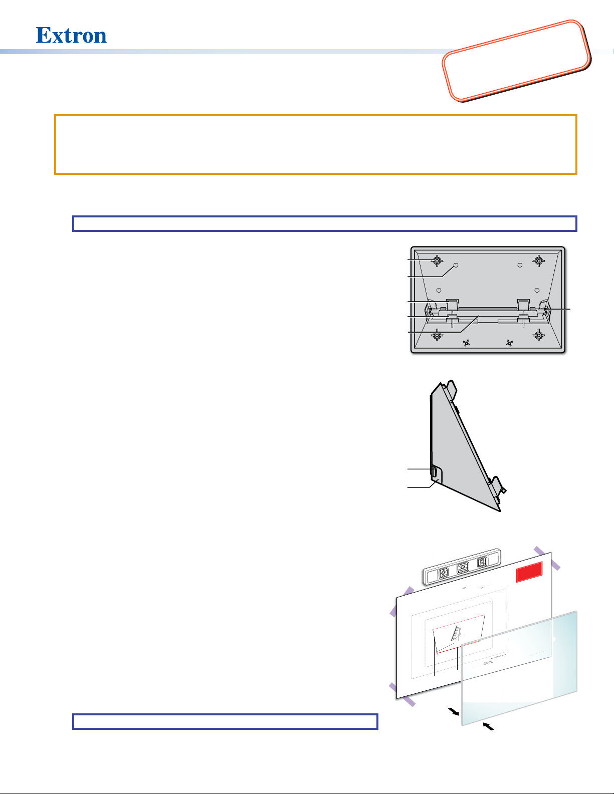
Figure 1. AMK Enclosure (front view)
Before Starting
To run cables to the back of the touchpanel, remove the cable access cover (see
gure 1, E) by releasing the catches (D) and pulling the cover away.
There is a slot on either side of the cover (see gure 2,
the at Ethernet cable. If you are using a larger cable, cut away the plastic tabs
) that can accommodate
G
(H) from the sides of the cover using a sharp knife along the groove in the plastic
(see gure 1, F).
To replace the cover, slide the tabs (
enclosure and press the catches (D) back into place.
) into the notches on the back of the
C
Option 1: Mounting the AMK to a Wall with Fasteners
To mount the AMK to a wall or furniture, drill holes through the four dimples in the
plastic (B) and attach the AMK. The installer must use screws and fasteners that
are appropriate for the mounting surface.
Option 2: Mounting the AMK to a Glass Surface
1. Clean both sides of the glass with a lint-free cloth and a 1:1 mixture of
isopropyl alcohol and water.
2. Place the alignment template on the inside glass surface (see gure 3,
Use tape (
) to attach the alignment guide to the glass. Use a level (3) to
2
1
ensure it is at the correct angle.
3. Remove the plastic backing from the adhesive patch on the back of the AMK.
TIP: Wet your ngers to prevent them from sticking to the adhesive patch.
Figure 2. AMK Enclosure (side view)
Alignment Template for the Extron
AMK 2 and AMK 3
(for mounting TLS Pro 725M, TLP Pro 725M, TLS Pro 1025M, and TLP Pro 1025M)
2.67"
(68 mm)
CATx cable entry
e
Bottom edge
).
Inside Glass
Surface
2
Adhesive surface
of AMK adhesiv
of AMK
1
Figure 3. Placing the Template
Outer edge of
TLS Pro 725M
3
Page size: 11" x 17"
Print scale 1:1
Do not shrink.
Installation Guide fo
1. See the Extron AMK 1, AMK 2, and
tructions.
s
n
rint
p
AMK 3
mplete i
o
ke sure
le-check the
c
Doub
2.
:1.
before printing. Ma
g, check tha
ettings are 1
ntin
adhesive patch
pri
s
4.63" (118 mm).
After
3.
ge of the AMK
d
e
(shown in red) is
P/N 68
r
settings
cale
the s
m
t the botto
23-02 Rev. A
-34
1
Page 2

AMK 1, AMK 2, and AMK 3 • Installation Guide (Continued)
TLS725M
Align
nt Templat
e for th
Extron
AMK 2 and
(for mounting TLS Pro 725M, TLP Pro 725M
, TLS Pro
ro
1025M, and
TLP
025M)
Page size: 11
x 17
le 1:1
Se
on
AMK 1, A
and
Instal
A
ati
f
or
let
e
instr
co
uct
Do
ble-c
the
nt set
t
t
ting
befo
ore
pr
i
r
intin
. M
a
ake sure
th
th
g.
e s
scale
settin
:1.
3.
After p
ng,
che
eck
the b
edg
e o
of
K
a
h
(show
n
in re
is 4
.
.63
Adhesive s
urface
MK
e
e
r edge of
TLS Pro 725M
ute
r e
dge of
TLS Pr
o 1025M
68
-3423-0
1 Rev. B
Top of AMK
r
4. Do one of the following (see gure 4, inset):
• Hold the AMK at an angle with the bottom away from the glass
and align the top edge of the AMK with the red dotted line on
the alignment template marked “Top edge of AMK...”. Rotate
the bottom of the AMK so that the adhesive pad attaches to the
glass.
• Hold the AMK at an angle with the top away from the glass and
align the bottom edge of the AMK with the red solid line on the
alignment guide marked “Bottom edge of AMK...”. Rotate the
top of the AMK so that the adhesive pad attaches to the glass.
5. Press the AMK rmly against the glass (see gure 4,
6. Remove the paper alignment template from behind the glass.
1
).
Mounting the Cover Overlay (Optional)
The cover overlay is not required for mounting the touchpanel, but can
improve the aesthetics of the AMK when it is viewed through the window
from inside the conference room.
TIP: Wet your ngers to prevent them from sticking to the adhesive
patch.
1. Remove the paper backing from the cover overlay.
2. Position the cover overlay behind the AMK enclosure and secure it to
the glass (see gure 5).
3. Use a credit card or similar at edge to remove any air bubbles.
ear panel
AMK panel
aligns to
red lines.
AMK 2 and AMK 3
Alignment Template for the Extron
(for mounting TLS Pro 725M, TLP Pro 725M, TLS Pro 1025M, and TLP Pro 1025M)
-3423-01 Rev. B
P/N 68
dge of
r e
o 1025M
Oute
TLS Pr
r edge of
Oute
TLS Pro 725M
e
Bottom edge
1
of AMK adhesiv
urface
MK
Adhesive s
of A
Figure 4. Attaching the AMK to the Glass
Cover
Overlay
Page size: 11" x 17"
Print scale 1:1
Do not shrink.
Installation Guide f
See the Extr
e
let
1.
AMK 3
inting. M
pr
comp
Double-check the pri
2.
before
settings are 1:1.
e of the AMK
After printing,
n in red) is 4
3.
edg
(show
on AMK 1, AMK 2, and
instructions.
ake sure
check that the bot
adhesive patch
or
the scale
nt settings
.63" (118 mm).
P/N 68-3423-02 Rev. A
tom
Mounting the Touchpanel
Figure 6 shows how to mount the TLS 725M to the AMK 2. Mount the other
touchpanels to the corresponding mounting kit in exactly the same way.
1. If required, remove the paper backing, and attach the LED overlay
to the back of the touchpanel (see gure 6, 1). This overlay covers
the rear panel LEDs so that they do not cause a distraction inside the
conference room.
2. Run cables through the gap left by removing the cable access cover
(see Before Starting on the previous page) to the AMK and through the
mounting plate.
Connect the cables to the touchpanel (see the user guide for your
touchpanel model).
3. Fasten the mounting plate (provided with the touchpanel) to the
metal plate that comes with the AMK, using the four provided
M3 screws (2).
4. Attach the Ethernet cable to the LAN/PoE input on the
rear panel of the touchpanel (see the user guide for your
touchpanel model).
5. The mounting plate for the 5" models has two hooks (one
in each top corner). The mounting plates for the 7" and 10"
models have four hooks (3), (one in each corner)
Position the touchpanel so that these hooks t into the slots
on the rear panel of the touchpanel (see the user guide for
your touchpanel model).
6. Slide the touchpanel down slightly so that the hooks are
seated securely in the slots.
7. The tongue at the bottom of the mounting plate (
) sits in the
4
groove in the bottom of the touchpanel (see inset, 5). Fasten
the touchpanel to the mounting plate by tightening the lock
screw (6).
Figure 5. Attaching the Cover Overlay
TOP
Mounting Plate
2
4
4
5
LED Overlay
1
1
3
TLS 725M
Back View
6
Figure 6. Mounting the TLS 725M to the AMK 2
© 2019 - 2020 Extron Electronics — All rights reserved (www.extron.com). All trademarks mentioned are the property of their respective owners.
2
Worldwide Headquarters: Extron USA West, 1025 E. Ball Road, Anaheim, CA 92805, 800.633.9876
68-3317-01 Rev. C
05 20
 Loading...