


EXTRICOM WLAN SYSTEM USER GUIDE
EXSW-400/800
EXSW-1200/2400
MULTI SERIES 1000
EXRP-20/40/30N
EXRP-20E/40E/40EN
For System Firmware Release 4.2
Document Version 4.0

Important Notice
:
Copyright
No part of this publication may be reproduced, stored in a retrieval system or transmitted, in any
form or by any means, photocopying, recording or otherwise, without prior written consent of
Extricom Ltd. No patent liability is assumed with respect to the use of the information contained
herein.
While every precaution has been taken in the preparation of this publication, Extricom Ltd. assumes
no responsibility for errors or omissions. The information contained in this publication and features
described herein are subject to change without notice. Extricom Ltd. reserves the right at any time
and without notice, to make changes in the product.
Copyright © 2010 Extricom Ltd. All rights reserved. The products described herein are protected
by U.S. Patents and may be protected by other foreign patents, or pending applications.
Read this user manual, safety instructions, and the release notes for your switch
firmware, before installing and operating the Extricom WLAN system.
Disclaimer
Extricom makes no representations or warranties whether express or implied, that the
Extricom wireless local area network (WLAN) system or any component thereof shall meet
the purchaser’s operating requirements or that system operation will be uninterrupted or
error-free. All WLANs, including the Extricom WLAN system, can potentially be affected by
outside sources of interference such as other broadcasting devices, radiation, device immunity
level, and other external sources of interference.

•
o
This equipment has been approved for mobile applications where the equipment is
to be used at distances greater than 20cm from the human body (with the exception
of hands, wrists, feet and ankles). Operation at distances of less than 20 cm is
strictly prohibited.
!
Changes or modification to equipment not expressly approved by Extricom Ltd. is
strictly prohibited and could void the user's license to operate the equipment.
Extricom access points are for indoor use only.
• The maximum antenna gain is 4dBi
• An Extricom access point includes multiple WLAN radio modules; each radio
module is configured separately and serves a different set of clients. There is
!
no relation between transmissions on different radio modules, hence :
o The same information cannot be transmitted over separate Radio
modules
o Radio modules cannot transmit simultaneously over the same radio
channel
Client can transmit and receive data through one Radio module.
Please check the release notes for your version of Extricom firmware, before
installing or operating the system. The relevant release notes supersede this user
guide.
The availability of some specific channels and/or operational frequency bands are country
dependent and the firmware programmed at the factory to match the intended destination. This
firmware setting is not accessible by the end user.
The Extricom WLAN System User Guide i

Federal Communication Commission and Industry Canada Interference Statement
This equipment has been tested and found to comply with the limits for a Class B digital device,
pursuant to Part 15 of the FCC and IC rules. These limits are designed to provide reasonable
protection against harmful interference in a residential installation. This equipment generates, uses
and can radiate radio frequency energy and, if not installed and used in accordance with the
instructions, may cause harmful interference to radio communications. However, there is no
guarantee that interference will not occur in a particular installation. If this equipment does cause
harmful interference to radio or television reception, which can be determined by turning the
equipment off and on, the user is encouraged to try to correct the interference by one of the
following measures:
• Reorient or relocate the receiving antenna
• Increase the separation between the equipment and receiver
• Connect the equipment into an outlet on a circuit different from that to which the receiver is
connected
• Consult the dealer or an experienced radio/TV technician for help
FCC Caution: Any changes or modifications not expressly approved by the party responsible for
compliance could void the user’s authority to operate this equipment.
This device complies with Part 15 of the FCC & IC Rules. Operation is subject to the following two
conditions:
1) This device may not cause harmful interference
2) This device must accept any interference received, including interference that may cause
undesired operation.
Important Note:
FCC and IC Radiation Exposure Statement
This equipment complies with FCC and IC radiation exposure limits set forth for an uncontrolled
environment. This equipment should be installed and operated with a minimum distance of 20 cm
between the radiator and your body.
This transmitter must not be co-located or operating in conjunction with any other antenna or
transmitter.
Operations in the 5.15-5.25 GHz band are restricted to indoor usage only, to reduce potential for
harmful interference to co-channel satellite systems.
The maximum antenna gain permitted (for devices in the 5725-5825 MHz band) must comply with
the e.i.r.p. limits specified for point-to-point and non point-to-point operation as appropriate, as
stated in section A9.2(3).
Sec. A9.2 (3): For the band 5725-5825 MHz, the maximum conducted output power shall not
exceed 1.0 W or 17 + 10 log10 B, dBm, whichever power is less. The power spectral density shall
not exceed 17 dBm in any 1.0 MHz band. The maximum e.i.r.p. shall not exceed 4.0 W or 23 + 10
log10 B, dBm, whichever power is less. B is the 99% emission bandwidth in MHz.
ii Disclaimer

Fixed point-to-point devices for this band are permitted up to 200 W e.i.r.p. by employing higher
gain antennas, but not higher transmitter output powers. Point-to-multipoint systems, omnidirectional applications and multiple co-located transmitters transmitting the same information are
prohibited under this high e.i.r.p. category. However, remote stations of point-to-multipoint systems
shall be permitted to operate at the point-to-point e.i.r.p. limit provided that the higher e.i.r.p. is
achieved by employing higher gain directional antennas and not higher transmitter output powers.
The Extricom WLAN System User Guide iii

Table of Contents
About This Guide .............................................................................................. 1
Audience .....................................................................................................................1
Conventions ................................................................................................................1
Safety Precautions .......................................................................................................1
Chapter 1 Introduction to the Extricom Wireless LAN System ....................................... 3
Overview of the Extricom WLAN System ...................................................................3
Features and Benefits ..................................................................................................4
Overview of the Extricom Switches .............................................................................7
Overview of the Multi Series 1000 Appliance Platform ...............................................9
Overview of the Extricom Access Points ................................................................... 11
Access Points with Internal Integrated Antennas ..................................................... 11
Access Points with Connectors for External Antennas ............................................. 12
A Typical Extricom Wireless Network Topology....................................................... 13
Switch Cascade (Multi Series 1000 Platform Only) ................................................. 14
Extricom Support for 802.11n.................................................................................... 15
Brief Overview of 802.11n ...................................................................................... 16
Chapter 2 Installing the Extricom WLAN System .......................................................... 19
Unpacking the Extricom WLAN System ................................................................... 19
Additional Equipment ............................................................................................... 19
Determining the Location of the Extricom Access Points ........................................... 20
EXSW-400/800/1200/2400/Multi Series 1000 Switch (EXSW-800G, EXSW-1600) .. 20
Extricom EXRP-20/20E/40/40E/30n/40En Access Points ......................................... 23
Connecting the Switch and Access Points .................................................................. 26
Mounting the Access Points (Optional) ...................................................................... 28
Chapter 3 Configuring the Extricom WLAN System ..................................................... 30
Accessing the Extricom Switch GUI .......................................................................... 30
When System Pop-up Windows Appear In Explorer 8 ............................................. 31
Using the Extricom Web Configuration Pages ........................................................... 31
Configuring LAN Parameters .................................................................................... 34
iv Table of Contents

Configuring WLAN Parameters................................................................................. 36
Configuring ESSIDs ............................................................................................... 36
Configuring WLAN Radios .................................................................................... 49
WLAN Wizard ......................................................... Error! Bookmark not defined.
ESSID Assignment ................................................... Error! Bookmark not defined.
Powering Access Points ............................................... Error! Bookmark not defined.
System Tools Configuration ........................................ Error! Bookmark not defined.
Applying Saved Changes .......................................... Error! Bookmark not defined.
Rebooting the Switch ................................................ Error! Bookmark not defined.
Maintenance tab ........................................................ Error! Bookmark not defined.
Time & Date Setting ................................................. Error! Bookmark not defined.
Setting Passwords for the Extricom Switch ............... Error! Bookmark not defined.
Upgrading Extricom Firmware .................................. Error! Bookmark not defined.
Upload a Switch Certificate and Key ......................... Error! Bookmark not defined.
Application.................................................................. Error! Bookmark not defined.
Advanced Configuration of the Extricom WLAN ........ Error! Bookmark not defined.
Configuring Redundancy .......................................... Error! Bookmark not defined.
Configuring Rogue ................................................... Error! Bookmark not defined.
Configuring Syslog & Monitor .................................. Error! Bookmark not defined.
Configuring SNMP ................................................... Error! Bookmark not defined.
Centralized Configuration Tab .................................. Error! Bookmark not defined.
IDS Tab .................................................................... Error! Bookmark not defined.
Portal Tab (Captive Portal)........................................ Error! Bookmark not defined.
Others Tab ................................................................ Error! Bookmark not defined.
Viewing Events and Reports ........................................ Error! Bookmark not defined.
Reports Window - Details ......................................... Error! Bookmark not defined.
Viewing an Overview of the Configuration .................. Error! Bookmark not defined.
Chapter 4 Troubleshooting .................................................... Error! Bookmark not defined.
Appendix A Internal Access Point Mounting Template.......... Error! Bookmark not defined.
The Extricom WLAN System User Guide v


!
!
About This Guide
This guide provides detailed instructions for installing, configuring, and troubleshooting the
Extricom EXSW-400/800/1200/2400 and Multi Series 1000 WLAN switches and Extricom EXRP20/40/30n and 20E/40E/40En UltraThin™ Access Points (APs).
This version of the user guide has been updated to include product changes up to and including
switch version 4.2.43.04.
Audience
This guide is intended for enterprise IT managers and system installers who are familiar with
installing and configuring networks.
Conventions
This is a note. It emphasizes important information to users.
This is a caution. A caution warns of possible damage to the equipment if a
-
procedure is not followed correctly.
A warning alerts you to important operating instructions.
Safety Precautions
Follow the instructions in the guide to ensure proper installation and operation of the switch and
APs.
The use of wireless devices is subject to the constraints imposed by local laws.
Operate the switch and APs in an indoor environment.
Disconnect the switch and APs from power sources before servicing.
The Extricom WLAN System User Guide 1

The switch and AP enclosure must not be opened by anyone other than an authorized
service representative.
To comply with FCC RF exposure compliance requirements, maintain a minimal separation
distance of at least 20 cm/8 inches between the AP and all persons.
The power cable included should not be used with any other electrical equipments other
than Extricom switches.
The switch contains an internal battery.
CAUTION - Always replace the battery with the same type to avoid the risk of
!
explosion.
Dispose of used battery according to the instructions provided with the new battery.
2 Introduction to the Extricom Wireless LAN System

Chapter 1
Introduction to the Extricom Wireless
LAN System
A Wireless Local Area Network (WLAN) based on the IEEE 802.11 standard enables laptops,
PDAs, phones, and other “Wi-Fi” equipped devices to wirelessly connect to the enterprise network.
However, large scale deployments of traditional cell-based WLANs, in which each access point
(AP) operates on a different channel than that of adjacent APs, have been hindered by issues such as
poor coverage, low capacity, high-latency mobility, and expensive interference analysis or site
survey and maintenance costs.
Extricom’s WLAN, on the other hand, takes a different and novel solution approach, by avoiding
the coverage and capacity trade-offs of traditional cell-based WLAN architecture. In addition, the
need for cell planning and interference analysis, a highly expensive aspect of owning a WLAN, is
also eliminated. Finally, Extricom’s innovative approach does away with most WLAN maintenance
tasks. Extricom’s WLAN System is specifically designed to provide increased network capacity,
seamless mobility, high level of security, and easy installation and configuration.
Overview of the Extricom WLAN System
The Extricom WLAN consists of a wireless switch (EXSW-400/800/1200/2400, &EXSW-1600
based on the Multi Series 1000 platform) connected to a set of UltraThin™ APs (EXRP-20/40/30n
and EXRP-20E/40E/40En). The Extricom WLAN system eliminates the concept of cell-planning
and replaces it with the “Channel Blanket” topology. In this topology, each Wi-Fi radio channel is
used on every access point to create continuous “blankets” of coverage. By using multi-radio APs,
the Extricom system is able to create multiple overlapping Channel Blankets from the same
physical set of devices, as illustrated in Figure 1.
The Extricom WLAN System User Guide 3
Figure 1: Four Channel Blanket Coverage

The Extricom solution is based on a fully centralized WLAN architecture, in which the switch
makes all of the decisions for packet delivery on the wireless network. In this configuration, the
access points (APs) simply function as radios, with no software, storage capability, or IP address.
Even the basics of connecting are different: clients associate directly with the switch, not with the
AP. The AP acts as an “RF conduit” to rapidly funnel traffic between the clients and the switch. The
Extricom architecture has essentially centralized the 802.11 logic in the switch, while distributing
the wireless electronics in the APs.
Centralization of the Wi-Fi environment enables enterprises to deploy 802.11a/b/g/n channels at
every AP, creating multiple overlapping “Channel Blankets” that leverage each of the radios in the
multi-radio UltraThin AP. Each channel’s bandwidth is delivered across the blanket’s service area
(i.e. the combined coverage of all APs connected to the switch), with interference-free operation and
consistent capacity throughout.
As the client moves throughout the blanket, different APs will be in the best position to serve the
client at different times. The switch always uses the uplink and downlink path that is optimal to
serve the client. While this is going on “behind the scenes,” the client never experiences an AP-toAP handoff (i.e. de-association and re-association), resulting in seamless mobility.
Within each Channel Blanket, the switch avoids co-channel interference by permitting multiple APs
to simultaneously transmit on the same channel only if they won’t interfere with each other. This is
the essence of the TrueReuse™ functionality.
Extricom supports the 802.11n standard. 802.11n builds upon existing 802.11 standards. 802.11n
can be used in both the 5 GHz and 2.4 GHz frequency bands, introduces enhancements to the MAC
and the PHY layer, and makes use of multiple-input multiple-output (MIMO) technology. MIMO is
a technology that employs multiple transmitter and receiver antennas to support simultaneous data
streams. Such technology is capable of increasing data throughput via enhancements such as spatial
multiplexing (data streams), 40MHz channel bonding, Block Acknowledgment and frame
aggregation, and use of spatial diversity to increase range.
Features and Benefits
Extricom’s WLAN system solution offers the following features:
Ease of deployment - No cell planning
Extricom’s architecture requires no cell planning and experiences no constraints due to RF
interference or channelization. Consequently, Extricom APs can be deployed wherever needed,
in any density or even varying density, to meet the desired end-client service level (stipulated in
terms of connection rate). The traditional site survey is therefore reduced to just physical
equipment installation planning.
Multi-Layer WLAN
Using multiple radio Access Points, a single set of APs enables deployment of multiple highdata-rate Channel Blankets with overlapping coverage, resulting in multiplied aggregate
capacity. Separate Channel Blankets also offer the unique ability to guarantee Quality of
Service by physically segregating different user types, traffic, and roles onto different channels.
4 Introduction to the Extricom Wireless LAN System

Same band operation
The Extricom WLAN system enables WLAN channels, in the same band (e.g. Channel 1, 6, and
11 in 2.4 GHz), to be simultaneously used within the same AP, to form overlapping Channel
Blankets using the same physical set of APs. It is possible to configure up to four channels of
same band when using EXRP-40/40E/40En APs.
TrueReuse bandwidth
TrueReuse technology multiplies the bandwidth of a standard 802.11 channel by dynamically
optimizing the reuse of each frequency. Within a Channel Blanket, up to three APs are
permitted to simultaneously transmit on the same channel, when the TrueReuse algorithm
determines that they can do this without causing each other co-channel interference.
Zero-latency mobility
In an Extricom WLAN, wireless device remains on the same channel everywhere within the
Channel Blanket. Inter-AP handoffs delays or packet loss do not occur as the client moves
across the range of different APs.
Wi-Fi Collaboration
Extricom’s patented Wi-Fi Collaboration technology in which all APs are able to receive on the
same channel, provides uplink path diversity for client transmissions, making the system highly
resistant to RF instabilities and outside interference.
Dense AP deployment
In an Extricom WLAN, APs can be deployed in any density convenient to the enterprise, to
achieve both blanket coverage and a guaranteed communications rate to all users. In fact, while
cell-based solutions shy away from dense deployments because of their inherent RF obstacles,
Extricom’s system performance actually increases with AP density.
Wire-line quality VoWLAN
Extricom’s Interference-Free architecture is perfectly suited for VoWLAN providing
zero-latency mobility, voice and data separation, reduced power consumption, and high RF
resiliency, all together resulting in superior voice performance.
IEEE 802.11n
Extricom architecture supports 802.11n both in the 2.4 GHz and in the 5GHz bands, using both
20MHz and 40MHz wide channels. The advantages of Extricom’s architecture are numerous in
the 802.11n setting. Among them is the unique ability to deliver full-bandwidth performance in
the 2.4GHz band, to both 802.11n and 802.11b/g devices. By contrast, cell-planning
architectures cannot be used with 802.11n 40MHz channel-bonding, since the number of non
overlapping channels is insufficient for this.
IEEE 802.11i support
Extricom’s products support WEP-64, WEP-128, WPA-TKIP, WPA2-AES (CCMP)
encryption. The authentication modes supported include: RADIUS (802.1x) and WPA
Pre-Shared Key (PSK).
Power save
Full power conservation management is enabled for associated mobile devices over unicast,
multicast, and broadcast frames. This is based on various IEEE 802.11 standard power-save
specifications such as PS-Poll and U-APSD for 802.11a/b/g devices, and SM & U-PSMP power
save for 802.11n devices.
The Extricom WLAN System User Guide 5

Centralized configuration
New switches are added to the network via a single Web interface either manually by the user,
or automatically using an Extricom protocol.
System redundancy
Extricom enables full redundancy by connecting two switches in a cascade or hot-standby
topology. The switchover parameters are user-configurable
SNMP
The Extricom system supports SNMP V2 based on standard and private MIBs, enabling the
user to configure the switch using SNMP Set operations, read switch status using SNMP Get
operation and determine the status of the system, including the status of APs and Redundancy,
using SNMP Traps. SNMP is provided for customers wishing to use their existing network
management system to administer multiple Extricom switches. Alternatively, the Extricom
EXNM-2000 network management software platform is available as a dedicated centralized
Extricom WLAN management system.
Multiple RADIUS & RADIUS Redundancy
The Extricom system supports multiple RADIUS servers per ESSID, enabling the user to set
redundancy between these RADIUS servers.
Network Time Protocol (NTP)
The Extricom system supports synchronization of the system clock over the network, thereby
ensuring accurate local time keeping with reference to radio and atomic clocks located on the
Intranet and/or Internet.
Fast Handoff (Opportunistic Key Caching) - WLAN clients roaming between APs of the
same channel blanket within a single switch’s coverage area will experience zero-latency
mobility. Clients roaming between different Extricom WLAN switches use the standard 802.11
handoff mechanism, which is further facilitated by the opportunistic key caching mechanism in
the 802.11i standard. In addition to this, the Extricom system speeds up 802.11i handoff
between Extricom switches by use of Extricom’s inter-switch protocol. This permits the client
to avoid repetitive 802.1x authentications, thereby enabling faster transition between Access
Points connected to different switches with minimal session interruption
Captive Portal – The Captive Portal technique compels any HTTP client to view a special web
page (usually for authentication purposes) before accessing the rest of the network. Captive
Portal turns a Web browser into a secure authentication device. This is done by intercepting an
internet access request and redirecting it to an Extricom local logging web page which may
require authentication, or simply display an acceptable use policy and require the user to agree.
MAC authentication – MAC authentication technique enables the Extricom switch to
authenticate WLAN devices via RADIUS server even if they have no native support for 802.1x.
This mechanism is normally used in “dumb” device WLAN topology (such as barcode readers)
where WLAN client authentication is to be managed via a central RADIUS server.
6 Introduction to the Extricom Wireless LAN System

Overview of the Extricom Switches
The Extricom WLAN switches are connected to Extricom APs to form an Extricom WLAN.
The Extricom EXSW-400, EXSW-800, EXSW-1200, and the EXSW-2400 switches are FastEthernet capable; the EXSW-1600 and EXSW-800G are GbE-capable switches based on the
Extricom Multi Series 1000 platform.
The EXSW-400 and EXSW-800 can connect to EXRP-20/40 or EXRP-20E/40E APs to provide
legacy 802.11a/b/g service with up to 4 or 8 APs respectively. Alternatively, these switches can
connect to EXRP-30n or EXRP-40En APs to provide 802.11n and 802.11a/b/g service. However,
both switches can support up to a maximum of two channel blankets, regardless of the Extricom AP
model that is being used.
The EXSW-1200 and EXSW-2400 can connect to EXRP-20/40 or EXRP-20E/40E APs to provide
legacy 802.11a/b/g service. Alternatively, these switches can connect to EXRP-30n or EXRP-40En
APs to provide 802.11n and 802.11a/b/g service; the EXSW-1200 can connect to up to 12 APs and
the EXSW-2400 switch can connect to up to 24 APs.
When deployed with EXRP-20/20E access points, the EXSW-1200/2400 switches support up to
two channel blankets, and when they are connected to EXRP-40/40E/40En access points, the
EXSW-1200 and 2400 switches support up to four channel blankets. When deployed with EXRP30n access points, the EXSW-1200/2400 can support up to three channel blankets, two with
802.11a/b/g/n support, and one with 802.11a/b/g support.
EXSW-1200/2400 switches are equipped with hardware for two LAN ports with 100 Mbps Ethernet
line speed. However, only one uplink port is used currently; the second port is reserved for future
port redundancy development. AP connectivity is also 100 Mbps.
The EXSW-800G and EXSW-1600 provide GbE speeds (1,000 Mbps) on both the AP ports and
LAN uplink port. The 800G and 1600 can connect to EXRP-20/40 or EXRP-20E/40E APs to
provide legacy 802.11a/b/g service. Alternatively, these switches can connect to EXRP-30n or
EXRP-40En APs to provide 802.11n and 802.11a/b/g service; the EXSW-800 can connect up to 8
APs and the EXSW-1600 can connect up to 16 APs.
When deployed with EXRP-20/20E access points, the EXSW-800G and 1600 switches support up
to two channel blankets, and when they are connected to EXRP-40/40E/40En access points, the
EXSW-800G and 1600 switches support up to four channel blankets. When deployed with EXRP30n access points, these switches can support up to three channel blankets, two with 802.11a/b/g/n
support, and one with 802.11a/b/g support.
Configuring a switch and its associated set of APs is as simple as configuring a single traditional
AP, greatly reducing the effort required to deploy and maintain the WLAN. Configuration is done
via a dedicated, secured Web interface that comes standard with every switch, or via the optional
EXNM-2000 Network Management System.
The Extricom WLAN System User Guide 7
The Extricom EXSW
-
1200 is derived from the EXSW
-
2400, with the same hardware
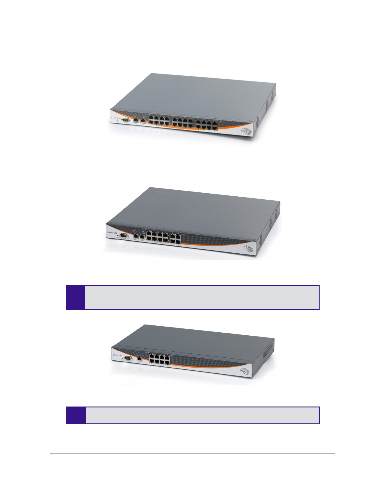
Figure 2: Extricom EXSW-2400 Switch
Figure 3: Extricom EXSW-1200 Switch
and firmware. The only difference between the two models is the number of WLAN
-
ports supported.
Figure 4: Extricom EXSW800 Switch
The EXSW800 switch only supports two channels, so when it is connected to EXRP-
40, only two radios will operate.
8 Introduction to the Extricom Wireless LAN System
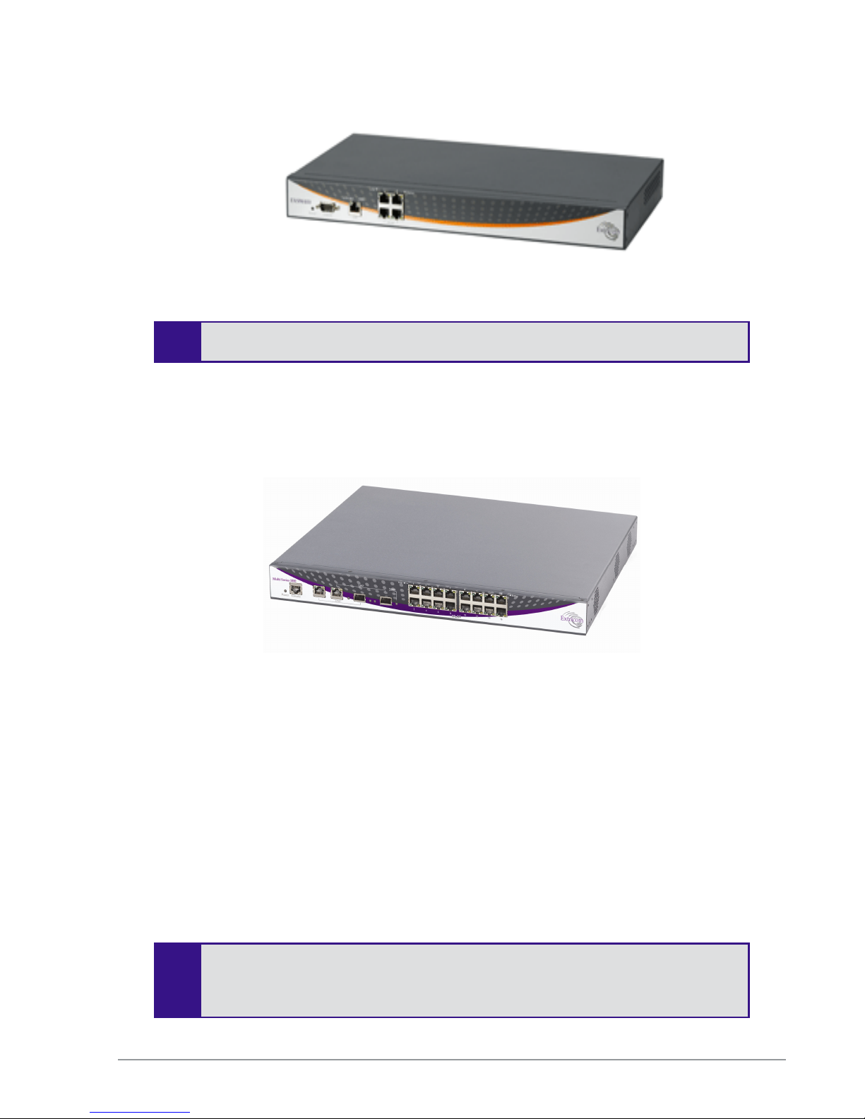
Figure 5: Extricom EXSW-400 Switch
The EXSW400 switch only supports two channels, so when it is connected to EXRP-
40, only two radios will operate.
Overview of the Multi Series 1000 Appliance
Platform
The Extricom Multi Series 1000 is a high-performance hardware platform, and is softwareconfigurable to support a range of wireless and networking functions in an Extricom WLAN
System.
The Multi Series 1000 is equipped with two RJ45/SFP GBE Combo port uplinks, and 16 GBE
PoE edge-side ports. The Multi Series 1000 is therefore capable of performing different wireless
and networking functions, depending on the firmware installed on it,
In the current release, the Multi Series 1000 platform is used to support the EXSW-1600, EXSW1600C, and EXSW-800G. The EXSW-1600, EXSW-1600C, and EXSW-800G are the ultimate
platforms for full 802.11n implementation.
Figure 6: Extricom Multi Series 1000
The EXSW-1600C is a special version of the EXSW-1600. The EXSW-1600C is
designed and licensed for use only as part of a Switch Cascade pair.
The Extricom WLAN System User Guide 9
The EXSW-1600 can be used as a standalone edge switch or as part of a Switch
Cascade pair.

SFP modules are not shipped with the Multi Series 1000. To use the SFP ports,
you must use Class 1 laser certified SFP modules according to IEC/EN 60825-1
and /or CDRH.
10 Introduction to the Extricom Wireless LAN System

Overview of the Extricom Access Points
Access Points with Internal Integrated Antennas
Extricom’s EXRP-20, EXRP-40 and EXRP-30n UltraThin APs are high-bandwidth devices. The
EXRP-20 contains two 802.11a/b/g radios, the EXRP-40 contains four 802.11a/b/g radios, and the
EXRP-30n contains two 802.11a/b/g/n and one 802.11a/b/g radio.
The EXRP-20 and EXRP-40 APs have internal diversity antennas – one diversity antenna for each
radio. The EXRP-30n possesses three (3) antennas per 802.11a/b/g/n radio (for supporting 3x3
MIMO).
The APs do not require configuration, enabling plug-and-play installation. If stolen, the APs do not
pose a security risk, since all encryption is performed in the switch.
With all intelligence residing in the WLAN switch, APs may be placed as close together as
necessary to provide high-quality, high-speed connectivity from all locations within the enterprise.
Extricom APs are connected to the Extricom WLAN Switch via standard Cat5e/6 cables. The APs
are powered by the standard 802.3af Power over Ethernet (PoE), and only a single Cat5e/6 cable
connection is required to support all radios in an Extricom AP.
An EXRE-10 or 1000 range extender can be used between the AP and the switch, for extended
reach.
Figure 7: Extricom EXRP-20 and EXRP-40 AP
The Extricom WLAN System User Guide 11
Figure 8: Extricom EXRP-30n AP

!
Access Points with Connectors for External Antennas
Some applications may require an access point capable of connecting to external antenna(s). The
EXRP-20E/EXRP-40E, and EXRP-40En accommodate this requirement. The EXRP-20E/EXRP40E have the same electronics as the EXRP-20/40 (respectively), but with a metal, plenum-rated
casing, and connectors for attaching external antennas. The EXRP-20E contains two 802.11a/b/g
radios and has four external antenna connectors. The EXRP-40E contains four 802.11a/b/g radios
and has eight external antenna connectors. The EXRP-40En contains two 802.11a/g/n radios and
two 802.11a/b/g radios. The EXRP-40En has ten external antenna connectors.
An external antenna may be desired to make the AP less visible by mounting it in the plenum. There
may also arise situations where, to ensure connectivity and service levels within a complex
coverage environment, directional antennas may be needed, rather than the omni-directional
antennas that are standard inside Extricom integrated antenna APs. In such cases, the antennas may
also be located at some distance from the AP in order to cover a specific area.
Figure 9: EXRP-20E/40E access points
The EXRP-20E/40E and EXRP-40En APs are connected to the Extricom WLAN Switch via
standard Cat5e/6 cables, in exactly the same manner as integrated antenna AP models. The APs are
powered by the standard 802.3af Power over Ethernet (PoE), but can be powered by an external
power supply if desired.
An antenna with an RP-SMA plug (male) connector can be connected to the EXRP-20E/40E and
EXRP-40En . For purposes of product homologation testing, Extricom used a “Rubber Duck”-type
antenna, specifically the Netgate 2.4-2.5 / 5.1-5.9 GHz Dual Band Rubber Duck RP-SMA (part
number: ANT-2458-5RD-RSP). More specifications on this antenna can be found at
http://www.netgate.com/product_info.php?products_id=386.
With EXRP-20E/40E/40En - Use only xPVC or similar jacket cable which is NEC
Article 725 and 444 Compliant and plenum rated per NFPA 262 (UL 910) standard
12 Introduction to the Extricom Wireless LAN System

A Typical Extricom Wireless Network Topology
An Extricom WLAN switch is connected to the wired LAN, and the APs distributed throughout the
enterprise. Figure 10 shows a typical Extricom enterprise topology, consisting of an Extricom
switch and eight APs.
Figure 10: Typical Extricom Typology
Extricom uses standard WLAN protocols (IEEE 802.11). As a result, any 802.11a/b/g/n standard
wireless device can work seamlessly with the Extricom system.
• Mixing different types of Extricom AP’s on the same switch is not
permitted, except for EXRP-20 and 20E AP’s or EXRP-40 and 40E
AP’s.
• When using the EXSW-400/800 with EXRP-40, EXRP-30n, or EXRP-
40En, only two radios will operate.
• Extricom APs must be directly connected to the switch to function.
• An Extricom range extender or media converter, may be used between
the AP and the switch, when extra range is required.
The Extricom WLAN System User Guide 13

Switch Cascade (Multi Series 1000 Platform Only)
Switch Cascade is a new Extricom topology in which two Multi Series 1000 switches are
interconnected together to create one larger logical switch with enhanced redundancy. One Multi
Series 1000 switch serves as the primary, and the other Multi Series 1000 switch serves as the
secondary. A diagram of the Cascade topology is shown below, in its standard configuration:
Figure 11: Switch Cascade Topology
The interconnect is connected to the LAN2 port of each switch. See page 26 for more details about
the interconnect hardware and maximum length.
The APs of each switch form a seamless channel blanket that extends across the APs of both
switches. Up to 4 seamless channel blankets can be deployed. Up to 32 APs can be deployed in the
cascade topology.
In the above topology, the switch configuration is redundant, but the APs are not. To achieve AP
redundancy, the APs from each switch should be deployed in a mesh configuration, as illustrated
below:
14 Introduction to the Extricom Wireless LAN System
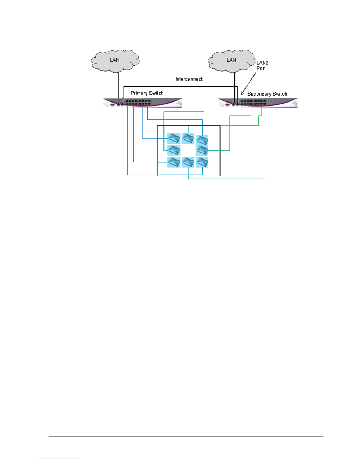
Figure 12: Switch Cascade With AP Redundancy
It is also possible to deploy the APs in a semi-mesh, according to the degree of service required in
the event of a failover. In a semi-mesh deployment, most APs are configured as in Figure 12, but
one or more APs from the Primary are placed in the coverage area of the secondary, or vice versa.
In a switch cascade, the secondary switch routes all of the traffic from its APs to the primary switch
over the interconnect cable. The primary switch performs the full set of Extricom edge switch
functions on the secondary switch’s traffic, as well as on traffic from its own APs. The same is true
for traffic downloaded to the APs: the primary switch performs the Extricom edge switch functions,
such as determining to which AP to transmit each packet, and the secondary switch routes the traffic
it receives to the correct AP.
Heartbeat checks are performed over the LAN links. A failover takes place if there is a critical
failure of one of the switches, one of the LAN links, or in the interconnect.
Extricom Support for 802.11n
802.11n is a breakthrough technology that enables Wi-Fi networks to do more, faster, over a larger
area. 802.11n Wi-Fi provides optimized connectivity for enterprise computer networking, delivering
the range, bandwidth, and performance that multimedia applications and products demand.
For 802.11n deployment, Extricom offers the EXRP-30n, and EXRP-40En APs. The EXRP-30n
contains two 802.11a/b/g/n radios and one 802.11a/b/g radio, and the EXRP-40En contains two
802.11a/b/g/n radios and two 802.11a/b/g radios.
All current Extricom switches support 802.11n. However, for new 802.11n deployments, the Multi
Series 1000 platform (EXSW-1600/800G) is recommended because of its GbE capability which
takes full advantage of the GbE capability of the EXRP-30 and 40En.
The Extricom WLAN System User Guide 15

Brief Overview of 802.11n
The following section describes at a high level the main features and terms of 802.11n. It also
outlines which features of the standard are supported by Extricom products at this time. This section
is provided to give customers using Extricom's 802.11n products an overview of 802.11n
technology, and to help them understand what parameters need to be to configured on the Extricom
switch in order to support 802.11n.
802.11n is a member of the 802.11 family of standards; it can function in both the 2.4 GHz and
5GHz bands using OFDM transmission (as with 802.11a and 802.11g). The emphasis in 802.11n
design was mainly on increasing bandwidth, range and performance of the 802.11 protocol itself.
This was largely achieved by using multiple transmitters/receivers (MIMO) and enhancements to
the OFDM PHY and 802.11 MAC layers.
MIMO
Definition: 802.11a/b/g devices used SISO architecture (single input, single output) for transmitter
and receiver paths. 802.11n uses MIMO (Multiple inputs / multiple outputs) architecture. That is,
multiple transmitter and multiple receiver antennas (NxM) are used to support multiple,
simultaneous data streams.
Extricom 802.11n: Extricom Access Points are equipped with three receivers and three
transmitters, so as to make 3x3 MIMO possible. Initially, however, the firmware in the radio chipset
will operate in a 3x2 MIMO configuration. This will be firmware upgradeable when the chipset
manufacturer makes this enhancement available.
Data Streams
Definition: Spatial multiplexing divides data into multiple streams and sends it simultaneously over
multiple paths using the multiple transmitters (antenna) over the channel. These streams are
recombined by the multiple receivers to get the original data.
Extricom 802.11n: Extricom Access Points support two data streams over the 3x3 transmitter/
receivers.
Channel Bonding
Definition: All earlier versions of 802.11 have used 20 MHz wide channels, defined in the 2.4 GHz
and 5 GHz bands. 802.11n- Draft 2.0 specifies operation in the same 20 MHz channels used by
802.11b/g in the 2.4 GHz and 802.11a in the 5 GHz bands, but adds a mode where a full 40-MHz
wide channel can be used. This offers approximately twice the throughput of a 20-MHz channel.
Extricom 802.11n: Extricom products support 20 and 40MHz channels both in 2.4GHz and 5GHz.
Guard Interval
Definition: In OFDM, inter-symbol interference occurs when the delay between different RF paths
to the receiver exceeds the guard interval, causing a reflection of the previous symbol to interfere
with the strong signal from the current symbol: a form of self-interference. 802.11n allows a shorter
guard interval to increase PHY performance.
Extricom 802.11n: Extricom supports configurable guard interval (400 or 800 ns). However, short
guard interval is only supported with 40MHz channel.
16 Introduction to the Extricom Wireless LAN System

Frame Aggregation
Definition: With MAC-layer aggregation, a station with a number of frames to send can combine
them into an aggregate frame (MAC MPDU). The resulting frame contains fewer headers in
overhead than would be the case without aggregating, and because fewer, larger frames are sent, the
contention time on the wireless medium is reduced.
Extricom 802.11n: Extricom supports frame aggregation.
Block Acknowledgment
Definition: Block Acknowledgment works in conjunction with frame aggregation, allowing the
transmitter to request a block ACK for a multiple frame improving overall performance.
Extricom 802.11n: Extricom supports block acknowledgment.
Operating Modes
Definition: 802.11n defines three modes of operation for 802.11n devices:
1. Legacy mode – In this mode, the 802.11n radio works in legacy 802.11a/b/g mode only.
2. Mixed mode – In this mode the 802.11n radio can work with both 802.11n & 802.11a/b/g
clients
3. Greenfield mode – In this mode the 802.11n radio works only with 802.11n clients.
Extricom 802.11n: Extricom products support both Legacy and Mixed modes. Currently there is no
support for Greenfield mode. With this release, however, Extricom is introducing a unique feature,
the "HT Only" blanket in which a specific Channel Blanket can be configured so that only 802.11n
clients (working in mixed mode) can associate to it. This enables a deployment to support coexistence of ‘n’ and ‘b/g’ clients, from the same set of APs, but separated on different channels, so
there is no mixed-mode throughput degradation occurs.
Coexistence
Definition: 802.11n is designed to operate with backward compatibility for 802.11b/g/a devices—
the method of operation known as mixed mode that was previously described. 802.11b/g/a, on the
other hand, does not have forward compatibility with 802.11n. Therefore 802.11n must protect
802.11b/g/a stations from 802.11n transmissions that may be interpreted as interference
Extricom 802.11n: Extricom supports PHY layer protection (L_SIG protection) for OFDM
transmissions (802.11a/g clients). MAC layer protection is supported (Dual CTS protection) for
non-OFDM (802.11b) clients.
MCS
Definition: The complexity of 802.11n rate adaptation has given birth to the concept of Modulation
Coding Scheme (MCS). MCS includes variables such as the number of spatial streams, modulation,
and the data rate on each stream.
Extricom 802.11n: Extricom supports two data streams; therefore MCS 0 to 15 can be configured.
The Extricom WLAN System User Guide 17

SM Power Save
Definition: The basic 802.11n power save mode is based on the earlier 802.11 power save function.
Power save in 802.11n is enhanced for MIMO operation with SM power save mode. Since MIMO
requires maintaining several powered-up receiver chains, standby power draw for MIMO devices is
likely to be considerably higher than for earlier 802.11 equipment. A new provision in 802.11n
allows a MIMO client to power-down all but one RF chain when in power save mode. When a
client is in the ‘dynamic’ SM power save state, the AP sends a wake-up frame, usually an RTS/CTS
exchange, to give it time to activate the other antennas and RF chains. In static mode, the client
decides when to activate its full RF chains, regardless of traffic status.
Extricom 802.11n: Extricom supports SM power save mode static mode.
18 Introduction to the Extricom Wireless LAN System

Chapter 2
Installing the Extricom WLAN System
This chapter provides instructions for unpacking and installing the Extricom WLAN system.
Unpacking the Extricom WLAN System
The Extricom WLAN system is shipped with the following:
One Extricom switch.
CD which contains The Extricom WLAN System User Guide, Release Notes and EULA
APs (the number of APs is based on customer order and provided in separate boxes) are
shipped as part of the overall order.
One power cable.
Additional Equipment
The following additional equipment is required for installing the Extricom WLAN system:
One CAT-5e/6 cable for each AP.
One CAT-5e/6 cable(s) for connecting the WLAN switch uplink to the LAN switch.
A range Extender (EXRE) is required for any AP that will be located between 100 and 200
meters from the WLAN switch.
For cabling distances over 200 m, media converters must be used.
Two (EXRP-20/40/30n) stainless steel pan head 8x1-1/4" self-tapping Phillips screws for
wall or ceiling mounting each AP (optional).
The Extricom WLAN System User Guide 19

Determining the Location of the Extricom Access
Points
Before installing the switch and access points, plan the placement of the APs. Before permanently
mounting the APs, Extricom recommends testing the network (using a laptop client) to identify
potential coverage holes. If such a problem exists, relocate an AP or add additional APs to resolve
the coverage hole. To find the best location for the required coverage, the Extricom Deployment
Tool may be used.
The APs should be placed in a stable, secure location, such as on top of a closet or bookshelf, or
mounted on a wall.
The switch should be placed near the distribution point of the LAN line. This is usually in the
communications closet of your enterprise.
EXSW-400/800/1200/2400/Multi Series 1000
Switch (EXSW-800G, EXSW-1600)
The Extricom EXSW-400 switch has 6 connectors and 4 LED types on the front panel (refer to
Figure 13).
The Extricom EXSW-800 switch has 10 connectors and 4 LED types on the front panel (refer to
Figure 14).
The Extricom EXSW-1200 switch has 15 connectors and 4 LED types on the front panel (refer to
Figure 15).
The Extricom EXSW-2400 switch has 27 connectors and 4 LED types on the front panel (refer to
Figure 16).
The Extricom Multi Series 1000 Appliance Platform has 21 connectors (refer to Figure 17).
Figure 13: Extricom EXSW-400 Switch
20 Installing the Extricom WLAN System
Figure 14: Extricom EXSW-800 Switch

RJ45 console
16
GbE/PoE copper ports
GbE Combo ports 2 Copper/SFP
Figure 15: Extricom EXSW- 1200 Switch
Figure 16: Extricom EXSW-2400 Switch
Figure 17: Extricom Multi Series 1000
Table 1 below describes the front panel and connectors of Extricom EXSW400/800/1200/2400/Multi Series 1000 switches.
Connectors Description
Console Serial connector – only to be used by, or as instructed by, Extricom
LAN 2 Fast Ethernet RJ-45 ports – used to connect the switch to the wired
The Extricom WLAN System User Guide 21
personnel for troubleshooting, support, or maintenance. Can be
accessed using a Null modem cable.

Connectors Description
(EXSW-400/800)
LAN1, LAN2
(EXSW- 1200/2400)
LAN1,LAN2
(Multi Series 1000)
WLAN (AP) Ports RJ-45 connectors – used to connect Extricom APs to the switch.
Table 1: Extricom EXSW-400/800/1200/2400/1600 Switch Connectors
LAN.
Only LAN1 is used for connection to the wired LAN.
2 GbE RJ-45, 2 GbE SFP combo ports – used to connect the switch
to the wired LAN. Use only GbE or SPF.
These ports provide 802.3AF PoE compatible power.
Maximum current: 270 mA, 48 volts.
LAN2 on EXSW-1200/2400 is currently not in use.
Only LAN1 is used for connection to the wired LAN.
LAN2 is used for Switch Cascade interconnect only.
Do not connect any device other than Extricom APs to
-
the WLAN ports.
Table 2 below describes the front panel LEDs of Extricom EXSW-400/800/1200/2400 and Multi
Series 1000 Appliance Platform.
LED Color Description
Power None
Green
Red
GreenOrange
LAN, LAN1, LAN2 Ports
Act/Link Green
100
(EXSW-400/800 only)
100 /1000
(EXSW-1200/2400 only)
Orange
Orange
No power
Blinking - switch is loading
On - switch is ready/operational
On - Error after loading
Blinking - RF localization error
On - connection
Blinking - activity over connection
Off - no connection
On - 100 Mbps full duplex connection
Off - 10Mbps full duplex or no connection
On - 100 Mbps full duplex connection
Off - No connection
Only a 100 Mbps LAN connection is
supported.
22 Installing the Extricom WLAN System

LED Color Description
(1000)
(Multi Series 1000 only)
Status (SFP links)
(Multi Series 1000 only)
Orange
Green
Not in use.
Only a 1000 Mbps LAN connection is
supported.
In v4.2, Orange LED is not used.
On - 1000 Mbps full duplex SFP connection
Off - no SFP connection
WLAN (AP) Ports
Link Green
Status
Orange
(EXSW400/800/1200/2400 only)
Status
Orange
(Multi Series 1000 only)
On - connection
Blinking - activity over connection
Off - no connection
On- 100 Mbps full duplex connection
Off - no connection
On - 1000 Mbps full duplex connection
Off -100 Mbps full duplex or no connection
Table 2: Extricom EXSW-400/800/1200/2400/1600 Switch LEDs
Extricom EXRP-20/20E/40/40E/30n/40En
Access Points
Extricom EXRP-20/40/30n APs have two connectors (AP to WLAN switch communication, power)
located on the side of the device and four LEDs located on the top of the device (see Figure 18).
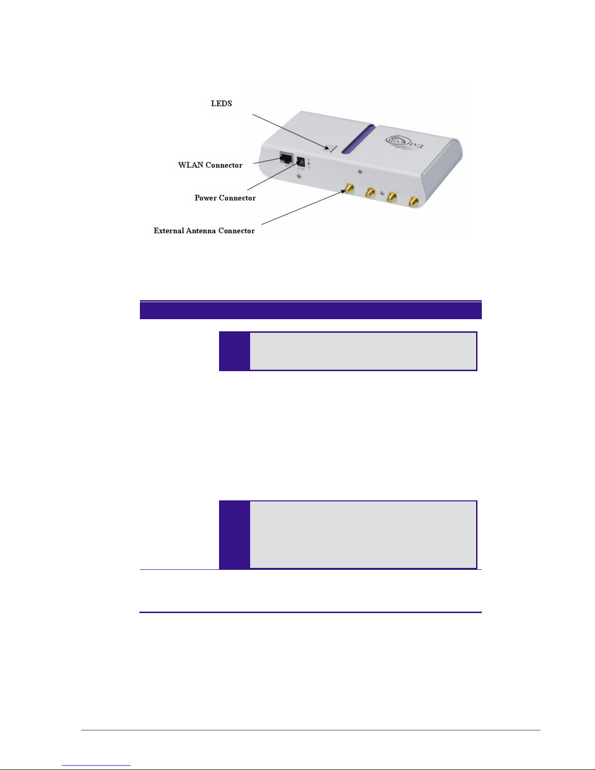
In addition to these two connectors, the EXRP-20E/40E APs also have four or eight external
antenna connectors respectively (see Figure 19). The EXRP-40En has 10 external antenna
connectors.
LEDs
LEDs
WLAN Connector
WLAN Connector
The Extricom WLAN System User Guide 23
Power Connection
Power Connection
Figure 18: Extricom Integrated Antenna AP
External power is not required for most
Due to regulatory
requirements
in
Figure 19: Extricom External Connector Antenna AP (EXRP-20E shown)
Table 3 below describes the Extricom Access Point connectors.
Connectors Description
Power
In case of an external power requirement (e.g. when media
converters are used and POE is blocked), use a UL Listed
LPS (Limited Power Source) or NEC Class II power
adapter. Rating – Input: 90-240VAC, 0.8A max. Output:
48VDC, 0.56A max.
The DC output plug of the power supply must be a standard
round DC plug with 5.5mm outer ring diameter and 2.5mm
inner ring diameter. Plug polarity: Outer (-), Inner (+).
WLAN RJ-45 connector – used to connect the Extricom AP to the
Extricom switch. Power is provided by the Extricom switch
to the AP when directly connected to it.
applications. Power is supplied via the Ethernet
cable (PoE).
Europe (CE) and the pending
certification process for the power
supply connector, an external power
-
supply should not be used with
EXRP20/40/20E/40E.
24 Installing the Extricom WLAN System
Table 3: Extricom AP Connectors

LEDs Color Description
Radio 1 Green 1st Radio is active
Red 1st Radio is malfunctioning
Off 1st Radio is off
Radio 2 Green 2nd Radio is active
Red 2nd Radio is malfunctioning
Off 2nd Radio is off
LAN Green (flashing) Connection to Extricom switch is active
Off Not active
Power Green On/Off
Table 4: Extricom EXRP-20/EXRP-20E AP LEDs
LEDs Color Description
Radio 1 Green 1st Radio is active
Red 1st Radio is enabled with no assigned
ESSID, or malfunctioning
Off 1st Radio is off
Radio 2 Green 2nd Radio is active
Red 2nd Radio is enabled with no assigned
ESSID, or malfunctioning
Off 3rd Radio is off
Radio 3 Green 3rd Radio is active
Red 3rd Radio is enabled with no assigned
ESSID, or malfunctioning
Off 3rd Radio is off
Radio 4 Green 4th Radio is active
Red 4th Radio is enabled with no assigned
ESSID, or malfunctioning
Off 4th Radio is off
Table 5: Extricom EXRP-40/EXRP-40E/En AP LEDs
The Extricom WLAN System User Guide 25

If an
AP
must be
located over 100 meters from the switch, an Extricom Range
LEDs Color Description
Radio 1 Green 1st Radio is active
Red 1st Radio is malfunctioning
Off 1st Radio is off
Radio 2 Green 2nd Radio is active
Red 2nd Radio is malfunctioning
Off 2nd Radio is off
Radio 3 Green 2nd Radio is active
Red 2nd Radio is malfunctioning
Off 2nd Radio is off
LAN Green (flashing) Connection to Extricom switch is active
Off Not active
Table 6: Extricom EXRP-30n LEDs
Connecting the Switch and Access Points
The Extricom switch is connected to the wired LAN and to the APs that are located throughout the
enterprise.
To connect a switch and access points:
1. Using CAT-5e/6 100/1000Mbps cable, connect the RJ-45 LAN1 connector located on the front
panel of the switch (refer to Figure 16) to the LAN switch.
2. Using a CAT-5e/6 cable, connect each AP (refer to Figure 16) to one of the switch’s RJ-45
WLAN connectors.
Extender must be used, which enables up to an additional 100m, for a total switch to
AP distance of up to 200m.
3. Connect the power cable to the power connector located on the rear panel of the switch, and
Switch to AP distances of up to 700m can be supported on GbE connections by using
Extricom EXMC-1000 media converters.
plug the other end of the power cable into a power source.
4. Verify that the Power LEDs on both the switch and connected APs are green.
26 Installing the Extricom WLAN System
Additional APs can be connected /disconnected while the switch is active.

Mixing AP types in the same deployment is n
ot permitted, except for EXRP
-
20
If using f
iber media
converter
s (ATI/100Mbps, CTC/1000Mbps)
to extend switch
-to-
and 20E APs, or EXRP-40 and 40E APs.
When using the EXSW400/800 with EXRP-30n/40E/40En APs, only two radios will
operate.
AP distance:
• Each converter requires external power
• Once all cables are connected (Switch – copper – converter – fiber –
converter – copper – AP) perform a port power down/up in the web GUI of
the switch to renew switch awareness of the AP connection.
• Fiber mode is Multi for 100Mbps
• Fiber mode can be Multi or Single for 1000Mbps per the SFP module
selected. Note both ends of the fiber termination must be in the same (SFP)
mode.
To connect a switch cascade:
1. Connect the primary and secondary switch to the LAN and to its APs, as directed in the section
above.
2. Verify that both switches are running the same firmware release, and that this is the newest
release that supports Switch Cascade.
3. Refer to the chart on the following page for important switch interconnect guidelines
4. Connect the switch interconnect from the LAN2 connector located on the front panel of the
primary switch, (refer to Figure 17) to the LAN2 connector located on the front panel of the
secondary switch.
The Extricom WLAN System User Guide 27

The maxim
u
m length o
f the
primary to secondary
switch interconnect is computed
Distance Between
Secondary
Max.
Switch
Interconnect
D
istanc
e
50 150
100 100
150 50
175 25
190 10
Distance Between
Secondary
Max.
Switch
Interconnect
D
istance
50 500
100 300
150 150
175 75
according to the following tables: (all distances in meters)
Interconnect Using CAT-5e/6 100/1000Mbps Cable:
Switch and Its Farthest AP
Interconnect Using Fiber Media Cable:
Switch and Its Farthest AP
Note: Beyond 100 m, copper-based cables require a range extender.
(Copper Interconnect Cable)
(Fiber Interconnect Cable)
Mounting the Access Points (Optional)
Extricom EXRP-20E/40E/40En APs can be mounted on the wall or ceiling. For this purpose, a
separate mounting bracket is provided for ease of installation. The bracket has two holes for
mounting to the wall, and one hole for a screw that mounts the AP to the bracket.
Extricom EXRP-20/40/30n APs can be mounted on the wall or ceiling. To mount the APs, you will
need two stainless steel pan head 8x1-1/4" self-tapping Phillips screws.
To mount the EXRP-20/40/30n Access Points:
1. Place the installation template (refer to Error! Reference source not found. in this Guide) on
the wall where you want to mount the AP.
2. Mark the "Point for Drilling" locations on the wall.
3. Screw the two stainless steel pan head 8x1-1/4" self-tapping Phillips screws into the wall
leaving enough of the screws protruding to enable you to hook the AP over the screw.
4. Align the holes on the back of the AP with the screws and slip the AP into place.
28 Installing the Extricom WLAN System

Position
the
EXRP
-
20/40
AP
so that the connectors are on the bot
tom left corner of
the AP.
The EXRP-20 and EXRP-40 are similar in appearance. Please double-check the LED
titles or label on the underside of the unit to make sure you have the right type of AP
for your deployment.
The EXRP-20E, EXRP-40E, and EXRP-40En resemble each other but have a
different number of external antenna connectors.
The Extricom WLAN System User Guide 29

Configuring the Extricom WLAN
System
Accessing the Extricom Switch GUI
After connecting the switch and AP, configure the Extricom WLAN system through Extricom’s
web configuration GUI using a terminal or PC connected to the same LAN as the switch.
To access the Extricom web configuration pages:
Chapter 3
1. In your Web browser, enter the following: https://<IP address of the switch>
where <IP address of the switch> is the IP address of the switch provided with your
purchase (for example, the URL should be https://1.2.3.4 if the IP address of the switch is
1.2.3.4). Note that https must be used, not http, in order to initiate a secure browsing session.
https initiates an SSL session with the switch.
If you did not receive a switch IP address with the switch, the factory default value
2. On the first login you will receive a notice in your browser that there is a problem with the
3. The Login page appears, as shown below in Figure 20:
for the switch IP address is 192.168.1.254.
If you are using the default IP settings, do not place a router between the user PC and
the switch.
website’s security certificate. Click on “Continue to this website (not recommended)”.
30 Configuring the Extricom WLAN System

Figure 20: Login Page
4. Enter your user name and password (as provided by your system installer) and click OK. The
Summary page appears.
If you did not receive a user name and password with your switch, use the following
factory default user name and password:
user name: admin
password: Switch1
The user name and password are case-sensitive.
When System Pop-up Windows Appear In Explorer 8
1. You will receive a notice in the pop-up window that there is a problem with the website’s
security certificate.
2. Press the tab key on your keyboard until you see the link “Continue to this website (not
recommended)”
3. Click on it.
System pop-up windows are used in only a few situations, for example, when clicking on System
Tools \Maintenance \Factory Defaults button.
Using the Extricom Web Configuration Pages
The Extricom Web Configuration pages have four main areas:
Switch image – The Extricom Web configuration page displays an image of the configured
switch (the EXSW400, EXSW800, EXSW-1200, Multiseries 1000, or the EXSW-2400); the
image shows dynamic status of the PoE of each AP port (grey= PoE off , green=PoE on).
Navigation tree
The Extricom WLAN System User Guide 31
Configuration Display, Work
Navigation
Event and Alarm Area
Configuration display, and editable work area (for some screens)
Event and alarm area
Tree
Area (for some screens).
Figure 21: Typical Web Configuration Page
The navigation tree provides access to the following Extricom Web configuration pages:
LAN Settings – used for configuring LAN parameters.
WLAN Settings – used for configuring WLAN parameters including ESSID-related
configuration and Radio configuration.
Access Points – used for viewing ports in use, and activating/deactivating PoE.
System tools – used for configuring general system parameters such as passwords, time &
date, firmware upgrade, etc.
Advanced– used for configuring advanced features such as redundancy, TrueReuse,
802.11d, IDS, SNMP, and Centralized Configuration parameters.
Events & Reports – used for viewing system events and performance reports.
Support & Feedback
32 Configuring the Extricom WLAN System

The work area displays the information selected in the navigation tree. Use this area to configure
Extricom system parameters, where applicable. Web configuration pages may include a Save
button; when this is selected, the configuration changes are applied to the offline configuration file.
If you wish to apply these parameters, select the Apply option in the System Tool web page; this
will start the reconfiguration process.
The event and alarm area will display real time SNMP trap messages, you can pause the traps by
selecting Pause.
Please see page 92 for more details.
If you do not select Apply option (in the System tool web page) after clicking Save,
the new configuration will only take effect after rebooting the switch
The Extricom WLAN System User Guide 33
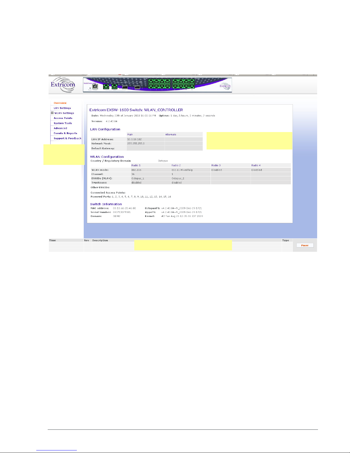
Configuring LAN Parameters
In the LAN Configuration page, you can configure the following:
The LAN ports’ IP address and network mask, as well as a backup address and mask.
The LAN interface and management VLAN tag IDs.
The default gateway.
Wireless subnet tab – Configures all wireless subnets (SSID subnets) controlled by the IT
manager. This may be required when Captive Portal is enabled.
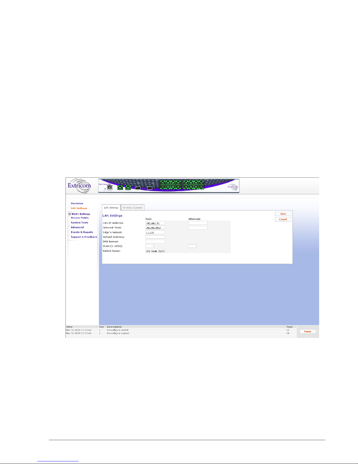
To configure LAN parameters:
1. Click LAN Configuration in the navigation tree. The LAN Configuration page appears (refer to
Figure 22).
2. Configure the LAN parameters. Refer to Table 7 for a description of the LAN parameters.
34 Configuring the Extricom WLAN System
Figure 22: LAN Configuration Page

If y
ou do not
select Apply
(in the
System tool
s web page)
after
selecting
Save
on
Field Description
LAN IP Address Enter LAN IP address used for the switch
management. You can add an alternate IP address if
you wish to manage the switch from a different
network; enter the value in the alternate field.
Network Mask Enter the network mask for the LAN 1 IP address and
you can also add an alternate network mask for the
alternate IP address defined, enter the value in the
alternate field.
Edge’s Subnet Subnet of a redundant pair (Primary - Secondary or
Main - Standby). Only appears if switch defined as
part of a redundant pair.
Default Gateway
DNS server Add the DNS server IP address
VLAN Management VLAN tag ID for VLAN access to
Switch name A textual descriptor of the switch. Maximum length
3. Click Save to save the configuration.
4. When using Captive Portal, if any Captive Portal ESSID has an associated VLAN, you need to
enter the IP subnet that you are planning to assign to this VLAN.
one page or more, when you reboot the switch the new configuration is lost. (refer
to Error! Reference source not found. on page Error! Bookmark not defined.).
Default gateway address.
manage the switch. You can add two: one for the
LAN 1 IP address through the Main field, and an
alternate VLAN id for the Alternate IP address
defined (using the alternate field).
is 64 characters.
Table 7: LAN Configuration Parameters
The Extricom WLAN System User Guide 35

On the
EXSW
-
1200, EXSW
-
2400, and Multi Series 1000
, up to 7 ESSIDs are
Configuring WLAN Parameters
The WLAN Configuration page contains three sub-menu pages:
ESSID definition
Radios
Assignments
Configuring ESSIDs
An ESSID (Extended Service Set Identifier) is the name of the network. Wireless devices must
connect to a specific ESSID which determines the pre-defined set of privileges, settings, and
limitations (such as security definitions, access privileges, VLAN assignments, etc.) of the network.
Each channel can support multiple ESSIDs, thus creating “virtual” networks on the same channel.
The following is the data structure used by the Extricom system:
Each radio is assigned one channel.
Each channel can support up to 8-16 different ESSIDs (see note below).
Each ESSID can be associated with a VLAN tag.
The same ESSID name can be repeated for different channels;
allowed on channel 1, and up to 8 ESSIDs are allowed on each of the remaining
channels.
Table 8 below shows an example of possible channel, ESSID and VLAN tag assignments for the
EXSW-400 and EXSW-800 switches.
On the EXSW-400 and EXSW-800, up to 15 ESSIDs are allowed on channel 1, and
up to 16 ESSIDs are allowed on channel 2.
There is a maximum of 31 ESSIDs per system.
Access Point Channel ESSID VLAN tag
First Radio 1 Network1 1
Second Radio 6 Network16 16
36 Configuring the Extricom WLAN System
Network2 2
… …
… …
Network15 15

Access Point Channel ESSID VLAN tag
Network17 17
Network18 18
… …
… …
Network31 31
Table 8: ESSID per channel Example
In the ESSID web page, it is possible to Add a new ESSID, and to Rename or Delete an existing
ESSID. For a selected ESSID it is possible to configure the following features:
Allow Default ESSID
Display ESSID in Beacon
Allow Store & Forward
Allow Inter-Ess Store & Forward
Enable Multicast
Enable ARP Caching
Enable MAC ACL
Enable 802.11D support
Enable AeroScout (Not supported in version 4.2)
MAC authentication
Beacon Rate Control
In-Band Management
Captive Portal
Assign a VLAN to the ESSID
Set a disassociation timeout
Set DTIM period
Encryption parameters
MAC ACL (in MAC ACL tab) / RADIUS server (in RADIUS tab)
The Extricom WLAN System User Guide 37
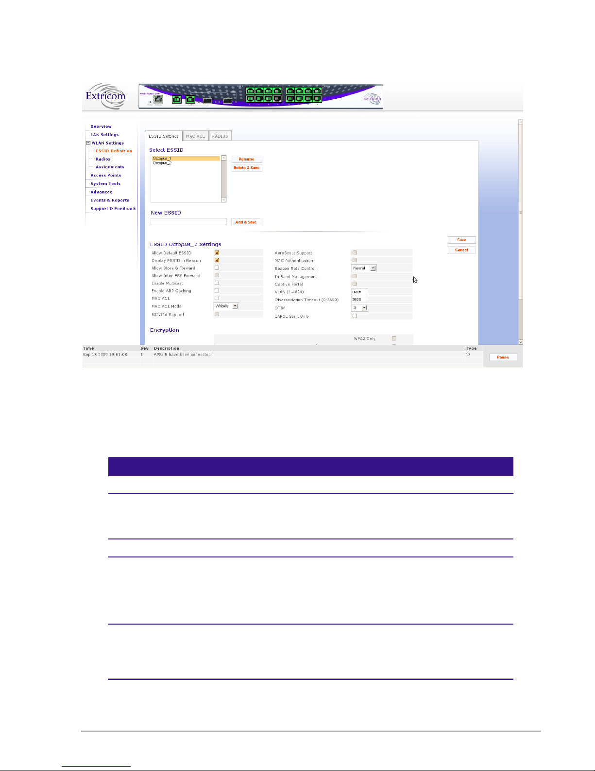
Figure 23: WLAN Configuration Page
When configuring ESSID parameters, refer to the following table for a description of the available
parameters:
Field Description
ESSID
Select ESSID Select an ESSID from the dropdown list.
To Add/Delete/Rename ESSIDs from this list, use the
Add/Delete/Rename field in the web page.
ESSID option
Allow Default ESSID If this option is enabled, a wireless device will be allowed to
connect to the Extricom WLAN without requesting a specific
ESSID (i.e., “default” or “any” ESSID). If this option is disabled,
then a wireless device needs to connect to a specific ESSID in the
Extricom WLAN.
Display ESSID in
Beacon
This option provides an additional (though limited) level of
security. The AP sends out a beacon with information about the
network. If this option is enabled, the ESSID appears in the
beacon. If disabled, the ESSID does not appear in the beacon.
38 Configuring the Extricom WLAN System

This option must be e
nabled on both
Field Description
Allow Store &
Forward
Allow Inter-Ess
Forward
If this option is enabled, two wireless devices connected to the
Extricom WLAN with the same ESSID can communicate and
transfer data to each other. Traffic between wireless devices will
not be forwarded to the LAN switch.
If this option is disabled, all traffic goes through the LAN switch.
This could be used by IT managers to apply security settings or
various policies in the LAN network.
Disabling Allow Store & Forward disables
If this option is enabled, two wireless devices connected to the
Extricom WLAN with different ESSIDs will be able to
communicate with each other without going through a router.
Traffic between wireless devices will not be forwarded to the LAN
switch.
the Allow Inter-Ess Forward option.
ESSIDs.
In order for wireless devices, associated to
different ESSIDs, to be able to
communicate with each other, the ESSIDs
must be defined on the same VLAN (or no
VLAN at all).
If this option is disabled, all traffic goes through the LAN switch.
This could be used by IT managers to apply security settings or
various policies in the LAN network.
Enable Multicast This option, when enabled, provides support of multicast and
broadcast packets for the selected ESSID. Multicast and/or
broadcast packets shall be transmitted from all APs.
Enable ARP Caching This option, when enabled, provides an immediate response to
ARP requests directed towards WLAN stations associated with the
selected ESSID. The Switch answers on behalf of the WLAN
stations.
MAC ACL This option, when enabled, allows a user to add a MAC access list
to the specific ESSID. Only clients with MAC address included in
this list are allowed to access the network if the ACL mode is
Whitelist. If the ACL mode is Blacklist, then these clients are not
allowed to use the network. Use the MAC ACL tab to add the MC
ACL list
MAC ACL Mode Select Whitelist or Blacklist. Whitelist mode means that the MAC
addresses listed can access the network. Blacklist mode means that
the MAC addresses listed cannot access the network.
The Extricom WLAN System User Guide 39

Field Description
802.11d Support Enables support of the 802.11d standard .The purpose of this
standard is to provide regulation domains for each country in a
predefined list. The regulation domains and country information
are provided as part of Beacons & Probe response.
Enable AeroScout Enable location based services based on the Aeroscout platform.
Requires Aeroscout hardware.
VLAN Enter a VLAN tag to assign to the ESSID. Assigning a VLAN to
an ESSID enables you to control a wireless device’s privileges
through the existing wired network definitions.
MAC Authentication Select this option if you wish to impose MAC authentication on
this ESSID. MAC authentication enables a user to authenticate
WLAN clients using RADIUS server, even if they do not support
802.1x authentication. Note that when using this option, the
security setting does not allow you to select any 802.1x methods.
Beacon Rate Control Use this option if you wish to tune the beacon distribution
mechanism. You can tune the system to provide customized
beacon coverage. The higher the rate, more beacons shall be
distributed on this SSID.
5 levels are available in the pull-down menu:
• Basic: 0% beacon rate control
• Normal (default): 33% beacon rate control
• Increased: 66% beacon rate control
• High: 80% beacon rate control
• Full: 100% beacon rate control
In Band Management Select this option if you wish to allow management of the switch
through the wireless media through this ESSID. In band
management ESSIDs have the same VLAN as set for the switch
management VLAN. Once you set this option, the VLAN setting
will be automatically updated to the management VLAN as set in
the LAN Configuration web page.
In band management SSID if enabled shall only allow the
following security Settings (This should be set from the Others
Tab in the Advanced page):
• WPA/WPA2 personal ( TKIP/AES & Pre Shared Key
Authentication)
• WPA/WPA2 Enterprise (TKIP/AES & 802.1x
Authentication)
Captive Portal Select this option if you wish to set this ESSID to be captive portal
restricted. If you set this option the ESSID VLAN id is
automatically assigned with the VLAN ID specified in the Portal
tab in the Advanced page.
40 Configuring the Extricom WLAN System

A high DTIM value may cause these
When this o
ption is selected, c
lients that
Field Description
Disassociation
Timeout
DTIM Period The period of time after which broadcast and multicast packets are
EAPOL Start Only Select this option if you want the switch to connect only clients
Enter the amount of time (in seconds) a wireless device can
remain inactive (no data sent to or from the wireless device)
before automatically disconnecting from the network.
transmitted to mobile clients in the Active Power Management
mode.
Select the DTIM period for the selected ESSID. This is relevant
for clients that want to utilize the power management capability.
The possible values are 1-5. The default is 3.
that require the switch to wait for an EAPOL Start.
Table 9: ESSID Parameter Descriptions
clients to lose connection with the
network.
do not send an EAPOL start will not be
able to connect to this ESSID.
Beacon Rate Control
The EXSW creates a hearing relationship table between APs. It forms an AP Bundles group
(Bundle of APs – group of APs, each bundle can include 1 or more APs). The total number of
bundles is equal to the number of APs. Each bundle can send a Beacon at the same time interval.
Then a transmission occurs based on round-robin between bundles (every 100msec). In order to
compensate sensitive clients for a lost beacon, it is possible to set (per SSID) the Beacon rate
control at a higher threshold. Although the feature minimizes the possibility of clients receiving
duplicate beacons, there is no guarantee of zero duplicate/missed beacons.
* Clients near AP1 hear only 1 beacon out of 5, therefore Hearing % is 20%.
Figure 24: Hearing Topology Example
The Extricom WLAN System User Guide 41

1 1 20
2 2,5 40
3 3,5 40
4 4,5 40
5 2,3,4,5
80
1 AP1
2
AP2
3 AP3
4
AP4
5 AP5
1 AP1,AP5
2
AP1,AP2
3 AP1,AP3,AP5
4
AP5,AP4
5 AP1,AP5
The following table shows the hearing % of each AP in the diagram above:
AP Receiving APs Hearing %
Table 10: Hearing %
Beacon transmission prior to switch s/w v3.4 would have followed the legacy pattern below:
Bundle/Interval BC1 BC2 BC3 BC4 BC5
Table 11: Legacy Pattern
However, from v3.4 and later, a Smart Beacon mechanism was implemented, so that the beaconing
in the example is actually as shown below (BC rate control of 80%):
Bundle/Interval BC1 BC2 BC3 BC4 BC5
42 Configuring the Extricom WLAN System
Table 12: Smart Beaconing

With some configurations, you can use encryption without authentication.
F
or a
Configuring Security Definitions
In the ESSID page Encryption section the following security definitions can be configured:
Type of encryption.
Type of authentication.
Security definitions are configured for each ESSID individually.
To configure the security definitions:
1. Select the ESSID for which you want to configure the security definitions from the ESSID
2. Configure the security definitions for the selected ESSID. Refer to Table 13 for a description of
higher level of security, however, it is recommended to use both encryption and
authentication.
The Extricom WLAN makes configuration of ESSID security parameters easier by
listing available combinations of Encryption and Authentication protocols.
dropdown list.
Security parameters.
The Extricom WLAN System User Guide 43

When choosing
an encryption cipher and authentication
The Extricom system supports “WPA2 Mixed Mode”.
Field Description
Encryption & Authentication
Choose method Define the method of encryption and authentication.
A combination of encryption and authentication methods may be
selected from the options detailed in the drop-down list.
Encryption cipher
There are three types of encryption ciphers available:
WEP64 – Wired Equivalent Privacy (802.11 encryption
protocol). This is a very basic encryption level. (AKA WEP40)
WEP128 – This encryption is similar to WEP64, but the WEP
keys are longer. (AKA WEP104)
TKIP – Temporal Key Integrity Protocol. This is a more secure
and more advanced method of encryption as a part of the WPA
standard.
AES (CCMP) – Advanced Encryption Standard.(Cipher Block
Chaining Message Authentication Code Protocol) is currently
the most advanced and secured method of Wi-Fi encryption
and is part of 802.11i (WPA2) standard.
Authentication method
Authentication is used to identify if a wireless device is authorized
to connect to the WLAN, and verifies the wireless device’s
identity. Authentication methods (such as specific EAP methods
available in the WPA/WPA2 enterprise option) also verify that the
association process is secured. Authentication utilizing
WPA/WPA2 (enterprise) can also support encryption key
changes.
The following methods are available:
802.1x – if the cipher is WEP or WEP104
WPA/WPA2 enterprise – if the cipher is TKIP or AES
Supported protocols: EAP, TLS, TTLS, PEAP, LEAP and MD5
Any security combination (Encryption and Authentication) can be
selected from the list and the check boxes.
method, make sure it is compatible with the wireless
devices’ capabilities.
This mode permits the coexistence of WPA and WPA2
clients on the same ESSID. WPA2 mixed mode allows
“old” WLAN clients with “new” WLAN clients on the
same ESSID during transition period.
44 Configuring the Extricom WLAN System

Field Description
WEP Keys The WEP Keys area is only enabled if the cipher selected in the
Choose Method field is WEP or WEP104. In the WEP Keys area,
you define the WEP Key that is used for encrypting or decrypting.
You can define all four WEP keys. For each key you define, select
the input format (ASCII or HEX) and enter the key according to
the following table:
Cipher ASCII HEX
WEP64
5 characters 10 digits
(or WEP64+802.1x)
WEP128
(or WEP128+802.1x)
13
characters
26 digits
Transmission Key Select the WEP64/WEP128 key to be used for transmitting data
from the AP.
WPA The WPA area is only enabled if the cipher selected in the Choose
Method field is WPA/WPA2 personal
WPA-PSK If WPA/WPA2 Personal with Pre-Shared key authentication is
used, the WPA-PSK field is enabled. In this case, select one of the
following input formats, and enter the corresponding key listed:
For ASCII, enter 8-63 characters.
For HEX, enter 64 digits.
WPA/RADIUS
Re-key Interval Enter the amount of time (in seconds) that elapses before the
Group Key is changed.
RADIUS Servers
Define the RADIUS servers list if:
The cipher is WEP64/WEP128, and the 802.1x authentication
method is selected.
The cipher is TKIP/AES, and the WPA/WPA2 Enterprise
authentication method is selected.
Use Server # 1 if only one server is used. Use
consecutive servers if several servers are used.
RADIUS Server-1
Select the RADIUS server #1 from the dropdown list of RADIUS
servers
RADIUS Server-2
Select the RADIUS server #2 from the dropdown list of RADIUS
servers
RADIUS Server-3
Select the RADIUS server #3 from the dropdown list of RADIUS
servers
RADIUS Server-4
Select the RADIUS server #4 from the dropdown list of RADIUS
servers
The Extricom WLAN System User Guide 45
Table 13: Security Definition Parameters

Encryption and Authentication methods.
The Choose Method dropdown list in Encryption & Authentication displays the following
options:
None
WEP64 (Open)
WEP128 (Open)
WEP64 & 802.1x Authentication
WEP128 & 802.1x Authentication
WPA/WPA2 personal ( TKIP/AES & Pre Shared Key Authentication)
WPA/WPA2 Enterprise (TKIP/AES & 802.1x Authentication)
When the “WPA2 Only” is checked, only Clients with WPA2 support are allowed to access the
WLAN.
When the “AES Only” is checked, only Clients with AES support are allowed to access the WLAN.
Cisco LEAP protocol (not CMIC & CKIP) is supported under “WEPxxx & 802.1x Authentication”.
46 Configuring the Extricom WLAN System
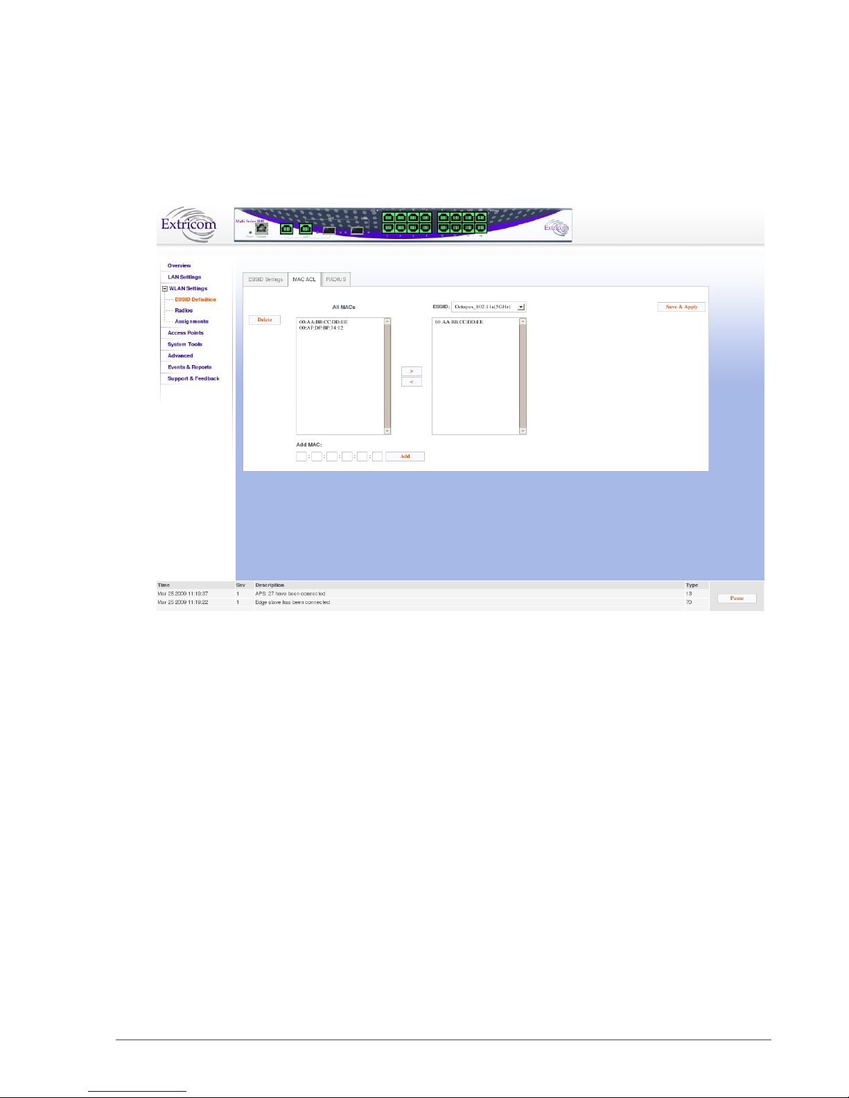
Configuring MAC ACL
To configure a per-ESSID MAC ACL, select the MAC ACL tab. In this sub-page, select the ESSID
you wish to set MAC ACL for.
Figure 25: MAC ACL configuration Tab
To configure MAC ACL per ESSID
1. Select an ESSID from a list of configured ESSIDs by selecting it from the dropdown list.
2. Select a MAC address from the All MACs list.
3. Use the Right Arrow/Left Arrow to insert/remove this MAC to/from the selected ESSID.
4. You can add a new MAC address to the All MACs list by inserting it manually in the Add
MAC field, then selecting Add. It is also possible to add a new MAC address to the All
MACs table from the Event Menu: when a new event message notifies you of a new client ,
the event message will has a + sign in the Add field , once you press it, it is automatically
added to the All MACs list.
5. Click Save & Apply to save the configuration and apply it immediately. There is no need to
use the main Apply page.
The Extricom WLAN System User Guide 47

Configuring RADIUS
RADIUS is a common authentication protocol utilized under the 802.1x security standard (often
used in wireless networks). Although RADIUS was not initially intended to be a wireless security
authentication method, it improves the WEP encryption key standard, when used in conjunction
with other security methods such as EAP-PEAP.
In an enterprise environment, several RADIUS servers may be used for backup and also for serving
different geographical locations. Up to four different RADIUS servers can be defined for each
ESSID. RADIUS redundancy is based on the assumption that the user database is identical in all
RADIUS servers and that users are listed in all servers with the same credentials.
Switchover from one RADIUS server to another takes place after consecutive failures of the server.
The order of priority is 1 to 4.
To configure the RADIUS server option, select the RADIUS tab. The RADIUS tab displays the
already configured RADIUS servers and allows you to configure new RADIUS servers in the
system RADIUS server bank, and also delete entries no longer needed.
Field Description
Server Name Enter the name of the RADIUS server.
Server Address Enter the address of the RADIUS server.
48 Configuring the Extricom WLAN System
Figure 26: Radius Configuration Tab

Field Description
Server Port Enter the RADIUS server port.
Server Password Enter the RADIUS server password.
Server Timeout Enter the time which the Extricom switch will wait for the
RADIUS server response.
Table 14: Radius Configuration Parameters
Configuring WLAN Radios
To configure the WLAN radios, use the Radios web page. The Radios web page provides the
options available for configuring the radios.
When the Radios page is initially displayed, it appears in abridged form. To see all of the
configuration options, you must click on the “More Options” button. Then, the window as shown in
Figure 27 below appears.
Note that when configuring 802.11a/b/g radios, the 802.11n displayed parameters cannot be
configured and are greyed-out.
The Extricom WLAN System User Guide 49
Figure 27: Radio Configuration Page

Use the
WLAN
Mode
dropdown checkbox to disable the radio
.
Not all Same Band
configurations are
Not all True
R
euse configuration
Configuring Radio Parameters
To configure specific radio parameters, select the appropriate Radio tab (Radio1-Radio4) on the
Radios web page.
Field Description
Channel Options
Disable
WLAN Mode Select the WLAN mode. Possible options are:
Disable - choose this option to disable the radio
802.11a
802.11b
802.11g
802.11b/g
802.11n/a
802.11n/g
802.11n/g/b
Rogue detection
possible, depending on type of Access
point connected, the configured radio
Channel Select the channel. The options available are based on the
country and WLAN mode.
Enable TrueReuse Enable the TrueReuse function on the selected radio.
More/Less Options Press this to maximize/minimize option display
Channel Blanket
state and whether TrueReuse is
configured across the switch. See the
Release Notes for possible configuration
scenarios.
scenarios are available. This depends on
what Bands are configured on all other
radios, the type of access point in use and
the configured Radio state. See the
Release Notes for possible configuration
scenarios.
50 Configuring the Extricom WLAN System

The Extricom WLAN System User Guide 51
 Loading...