

Extricom EXSW-800, EXRP-40, EXRE-10, EXSW-2400, EXSW-1200 User Manual
...
EXTRICOM WLAN SYSTEM
SER GUIDE
U
EXSW-800
EXSW-1200
EXSW-2400
EXRP-20
EXRP-40
EXRE-10
Version 3.1


Copyright
No part of this publication may be reproduced, stored in a retrieval system or transmitted, in any
form or by any means, photocopying, recording or otherwise, without prior written consent of
Extricom Ltd. No patent liability is assumed with respect to the use of the information contained
herein.
While every precaution has been taken in the preparation of this publication, Extricom Ltd. assumes
no responsibility for errors or omissions. The information contained in this publication and features
described herein are subject to change without notice. Extricom Ltd. reserves the right at any time
and without notice, to make changes in the product.
Copyright © 2007 Extricom Ltd. All rights reserved. The products described herein are protected
by U.S. Patents and may be protected by other foreign patents, or pending applications.
Important Notice:
"
Read this user manual and safety instructions before installing and operating the
Extricom WLAN system.
Disclaimer
Extricom makes no representations or warranties, whether express or implied, that the
Extricom wireless local area network (WLAN) system or any component thereof shall meet
the purchaser’s operating requirements or that system operation will be uninterrupted or
errorfree. All WLANs, including the Extricom WLAN system, can potentially be affected by
outside sources of interference such as other broadcasting devices, radiation, device immunity
level, and other external sources of interference.


Declaration of Conformity
Manufacturer’s Name: Extricom Ltd.
Declares under our sole responsibility that the products:
Product Names: Extricom EXSW-800, EXSW-2400, EXSW-1200
Conform(s) to the following standard(s) or other normative document(s):
EMC: FCC Part 15 Class B
EN 300386
VCCI V-3/2001.04
ANATEL Resolution 237
Safety: EN 60950-1
UL 60950-1
IEC 60950-1
ANATEL Resolution 238
Environmental: EU Directive 2002/95/EC of January 27, 2003, on the Restriction of the Use of
Certain Hazardous Substances in Electrical and Electronic Equipment (RoHS)
The Extricom WLAN System User Guide i

Manufacturer’s Name: Extricom Ltd.
Declares under our sole responsibility that the product:
Product Name: Extricom EXRP-20 & EXRP-20D
Conforms to the following standard(s) or other normative document(s):
EMC: FCC Part 15 Class B
EN 301489
VCCI V-3/2001.04.
Radio: FCC Part 15 C
FCC Part 15 E
EN 300328
EN 301893
Japan Type Certificate: Article 2, clause 1
ANTEL Resolution 365
Safety: EN 60950-1
UL 60950-1
IEC 60950-1
Environmental: EU Directive 2002/95/EC of January 27, 2003, on the Restriction of the Use of
Certain Hazardous Substances in Electrical and Electronic Equipment (RoHS)
Product Name: EXRP-40
Conforms to the following standard(s) or other normative document(s):
EMC: FCC Part 15 Class B
EN 301489
VCCI V-3/2001.04.
Radio: FCC Part 15 C
FCC Part 15 E
EN 300328
EN 301893
Japan Type Certificate: Article 2, clause 1
Safety: EN 60950-1
UL 60950-1
IEC 60950-1
Environmental: EU Directive 2002/95/EC of January 27, 2003, on the Restriction of the Use of
Certain Hazardous Substances in Electrical and Electronic Equipment (RoHS)
ii Declaration of Conformity

Table of Contents
About This Guide..................................................................................................1
Audience..........................................................................................................................1
Conventions.....................................................................................................................1
Safety Precautions...........................................................................................................1
Chapter 1 Introduction to the Extricom Wireless LAN System ........................................3
Overview of the Extricom WLAN System .....................................................................3
Features and Benefits ......................................................................................................4
Summary.......................................................................................................................6
Overview of the Extricom Switches................................................................................7
Overview of the Extricom Access Point .........................................................................9
Overview of the Extricom Repeater..............................................................................10
Chapter 2 Installing the Extricom WLAN System............................................................13
Unpacking the Extricom WLAN System......................................................................13
Additional Equipment Needed (Not Provided By Extricom)........................................13
Determining the Location of the Extricom Access Points ............................................14
The Extricom EXSW-800/1200/2400 Switch...............................................................14
The Extricom Access Points..........................................................................................16
The Extricom Repeater..................................................................................................18
Connecting the Switch and Access Points.....................................................................19
Mounting the Access Points (Optional) ........................................................................19
Chapter 3 Configuring the Extricom WLAN System .......................................................21
Using the Extricom Web Configuration Pages..............................................................22
Configuring the LAN Parameters..................................................................................24
Configuring the WLAN Parameters..............................................................................26
Configuring SSIDs........................................................................................................30
Configuring Security Definitions..................................................................................35
Advanced Configuration of the Extricom WLAN Architecture....................................39
Centralized Configuration Settings ...............................................................................44
The Extricom WLAN System User Guide iii

Access Points Powering ................................................................................................46
Configuration of the Extricom WLAN Architecture Utilities.......................................48
Viewing the System Configuration File .....................................................................49
Configuration File Backup..........................................................................................49
Uploading a New Configuration File..........................................................................50
Restoring System Defaults..........................................................................................50
Upgrading the Extricom Firmware.............................................................................50
Rebooting the Extricom Switch..................................................................................51
Reconfigure Switch - Smart Configuration ................................................................51
Setting the Time and Date...........................................................................................51
Setting Passwords in the Extricom Switch....................................................................53
Viewing Reports and Events Log..................................................................................53
Viewing a Summary of the Updated Configuration......................................................54
Viewing Extricom Information .....................................................................................56
Chapter 4 Troubleshooting..................................................................................................57
Appendix A Specifications...................................................................................................... 59
Extricom Switch Specifications ....................................................................................59
Extricom Access Point Specifications...........................................................................61
Extricom PoE Range extender specificathion...............................................................64
Appendix B Access Point Mounting Template..................................................................... 65
iv Table of Contents

About This Guide
This guide provides detailed instructions for installing, configuring, and troubleshooting the
Extricom EXSW-800/1200/2400 WLAN switches and Extricom EXRP-20/40UltraThin™ Access
Point (AP) .
Audience
This guide is intended for enterprise IT managers and system installers who are familiar with
installing and configuring networks.
Conventions
"
This is a note. It provides additional information to users.
This is a caution. A caution warns of possible damage to the equipment if a
-
procedure is not followed correctly.
A warning alerts you to important operating instructions.
!
Safety Precautions
Follow the instructions in the guide to ensure proper installation and operation of the switch and
APs.
The use of wireless devices is limited to the constraints imposed by local laws.
!
z Operate the switch and APs in an indoor environment.
z Disconnect the switch and APs from power sources before servicing.
The Extricom WLAN System User Guide 1

z The switch and AP enclosure must not be opened by anyone other than an authorized
service representative.
z To comply with FCC RF exposure compliance requirements, maintain a minimal separation
distance of at least 20 cm/8 inches between the AP and all persons.
z The switch contains an internal battery.
z Always replace the battery with the same type to avoid the risk of explosion.
!
z Dispose of used battery according to the instructions provided with the new battery.
2 Introduction to the Extricom Wireless LAN System

Chapter 1
Introduction to the Extricom Wireless
LAN System
A Wireless Local Area Network (WLAN) based on the IEEE 802.11 standard enables laptops,
PDAs, phones, and other “Wi-Fi” equipped devices to wirelessly connect to the enterprise network.
However, large scale deployments of traditional cell-based WLANs, in which each access point
(AP) operates on a different channel than that of adjacent APs, have been hindered by issues such as
poor coverage, low capacity, high-latency mobility, and expensive interference analysis or site
survey and maintenance costs.
Extricom’s WLAN, on the other hand, is a completely new solution. Referred to as the Interference-
™
Free
architecture, it eliminates the coverage and capacity trade-offs of traditional cell-based
WLAN architecture. In addition, the need for cell planning and interference analysis, a highly
expensive aspect of owning a WLAN, is also eliminated. Finally, Extricom’s innovative approach
does away with most WLAN maintenance tasks. Extricom’s WLAN System is specifically designed
to provide increased network capacity, seamless mobility, high level of security, and easy
installation and configuration.
Overview of the Extricom WLAN System
The Extricom WLAN consists of a wireless switch (EXSW-800/1200/2400) connected to a set of
UltraThin™ APs (EXRP-20/40). The Extricom WLAN system eliminates the concept of cellplanning and replaces it with the “channel blanket” topology. In this topology, each Wi-Fi radio
channel is used on every access point to create continuous “blankets” of coverage. By using multiradio APs, the Extricom system is able to create multiple overlapping channel blankets from the
same physical set of devices, as illustrated in Figure 1.
The Extricom WLAN System User Guide 3

Figure 1. Two Channel Blanket Coverage
The Extricom solution is based on a fully centralized WLAN architecture, in which the switch
makes all of the decisions for packet delivery on the wireless network. In this configuration, the
access points (APs) simply function as radios, with no software, storage capability, or IP address.
Even the basics of connecting are different: clients associate directly with the switch, not with the
AP. The AP acts as an “RF conduit” to rapidly funnel traffic between the clients and the switch. The
Extricom architecture has essentially centralized the 802.11 logic in the switch, while distributing
the wireless electronics in the APs.
Centralization of the Wi-Fi environment enables enterprises to deploy 802.11a/b/g channels at every
AP, creating multiple overlapping “channel blankets” that leverage each of the radios in the multiradio UltraThin AP. Each channel’s bandwidth is delivered across the blanket’s service area (i.e. the
combined coverage of all APs connected to the switch), with interference-free operation and
consistent capacity throughout.
As the client moves throughout the blanket, different APs will be in the best position to serve the
client at different times. The switch always uses the uplink and downlink path that is optimal to
serve the client. While this is going on “behind the scenes,” the client never experiences an AP-toAP handoff (i.e. de-association and re-association), resulting in seamless mobility.
Within each channel blanket, the switch avoids co-channel interference by permitting multiple APs
to simultaneously transmit on the same channel only if they won’t interfere with each other. This is
the essence of the TrueReuse™ functionality.
Features and Benefits
Extricom’s WLAN system solution offers the following features:
z Ease of deployment - No cell planning
Extricom’s architecture requires no cell planning and experiences no constraints due to RF
interference or channelization. Consequently, Extricom APs can be deployed wherever needed,
in any density or even varying density, to meet the desired end-client service level (stipulated in
terms of connection rate). The traditional site survey is therefore reduced to just physical
equipment installation planning.
4 Introduction to the Extricom Wireless LAN System

z Multi-Layer WLAN
Using multiple radio Access Points, a single set of APs enables deployment of multiple highdata-rate channel blankets with overlapping coverage, resulting in multiplied aggregate
capacity. Separate channel blankets also offer the unique ability to guarantee Quality of Service
by physically segregating different user types, traffic, and roles onto different channels.
z Same band operation
The Extricom WLAN system enables two WLAN channels, in the same band (e.g. Channel 1
and 6 in 2.4 GHz), to be simultaneously used within the same AP, to form overlapping channel
blankets using the same physical set of APs.
z TrueReuse bandwidth
TrueReuse technology multiplies the bandwidth of a standard 802.11 channel by dynamically
optimizing the reuse of each frequency. Within a channel blanket, up to three APs are permitted
to simultaneously transmit on the same channel, when the TrueReuse algorithm determines that
they can do this without causing each other co-channel interference.
z Zero-latency mobility
In an Extricom WLAN, wireless device remains on the same channel everywhere within the
channel blanket. Inter-AP handoffs delays or packet loss do not occur as the client moves across
the range of different APs.
z WiFi collaboration
Extricom’s patented WiFi Collaboration
technology in which all APs are able to receive on the
same channel, provides uplink path diversity for client transmissions, making the system highly
resistant to RF instabilities and outside interference.
z Dense AP deployment
In an Extricom WLAN, APs can be deployed in any density convenient to the enterprise, to
achieve both blanket coverage and a guaranteed communications rate to all users. In fact, while
cell-based solutions shy away from dense deployments because of their inherent RF obstacles,
Extricom’s system performance actually increases with AP density.
z Wire-line quality VoWLAN
Extricom’s Interference-Free architecture is perfectly suited for VoWLAN providing
zero-latency mobility, voice and data separation, reduced power consumption, and high RF
resiliency, all together resulting in superior voice performance.
z IEEE 802.11i support
Extricom’s products support WEP-64, WEP-128, WPA-TKIP, WPA2-AES (CCMP)
encryption. The authentication modes supported include: RADIUS (802.1x) and WPA
Pre-Shared Key (PSK).
z Power save
Full power conservation management is enabled for associated mobile devices over unicast,
multicast, and broadcast frames. For multicast and broadcast frames, the DTIM (Delivery
Traffic Indicator Message) period is configurable.
z Centralized configuration
New switches are added to the network via a single Web interface either manually by the user,
or automatically using an Extricom protocol.
The Extricom WLAN System User Guide 5

z System redundancy
Extricom enables full redundancy by connecting two switches in parallel to different APs over
the same area. The switchover parameters are user-configurable, and the Active to Standby
switchover is seamless to the user.
z SNMP traps
The Extricom system supports SNMP traps, enabling the user to determine the status of the
system, including the status of APs and Redundancy statuses.
z Rogue AP Detection
The Extricom system supports Rogue AP detection and reporting without the need for
additional hardware. By using one radio in each of the multi-radio APs, the Extricom Rogue AP
solution delivers the benefits of a dedicated security sensor network, without the costs of such a
physical overlay.
z Multiple RADIUS & RADIUS Redundancy
The Extricom system supports multiple RADIUS servers, enabling the user to set redundancy
between these RADIUS servers.
z Network Time Protocol (NTP)
The Extricom system supports synchronization of the system clock over the network, thereby
ensuring accurate local time keeping with reference to radio and atomic clocks located on the
Intranet and/or Internet.
z Fast Handoff (Opportunistic Key Caching)
The Extricom system speeds up the handoff of 802.11i WLAN stations between Extricom
switches by use of Extricom’s inter switch protocol. This technique enables the client to avoid
repetitive 802.1x authentications, thereby enabling faster transition between Access Points
connected to different switches with minimal session interruption.
Summary
The Extricom WLAN eliminates the cost and complexity of cell planning and site surveys for
interference analysis. The Multi-Layered blankets provide high-capacity, zero latency (seamless)
mobility, high level of security and ease of deployment wireless network.
6 Introduction to the Extricom Wireless LAN System
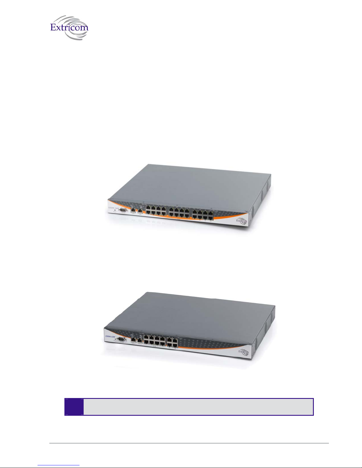
Overview of the Extricom Switches
The Extricom EXSW-800 the EXSW-1200 and the EXSW-2400 switches provide central control
and configuration of the WLAN. The switches implement the Interference-Free architecture in the
Extricom WLAN. The WLAN switches are connected to EXRP-20 or the EXRP-40 access points to
form Extricom WALN network.
The EXSW-800 switch can connect up to 8 EXRP-20 APs each with two 802.11a/b/g radios, to
provide two channel blankets.
The EXSW-1200 and the EXSW-2400 can connect to the EXRP-20 or the EXRP-40 APs, the
EXSW-1200 can connect to 12 while the EXSW-2400 switch can connect up to 24 APs. Each with
two or four 802.11a/b/g radios, to provide two or four channel blankets.
"
Figure 2. Extricom EXSW-2400 Switch
Figure 3 Extricom EXSW-1200 Switch
The Extricom EXSW-1200 is derived from the EXSW-2400, it is based on the same
Hardware and Software , however , it supports 12 instead of 24 WLAN ports
The Extricom WLAN System User Guide 7
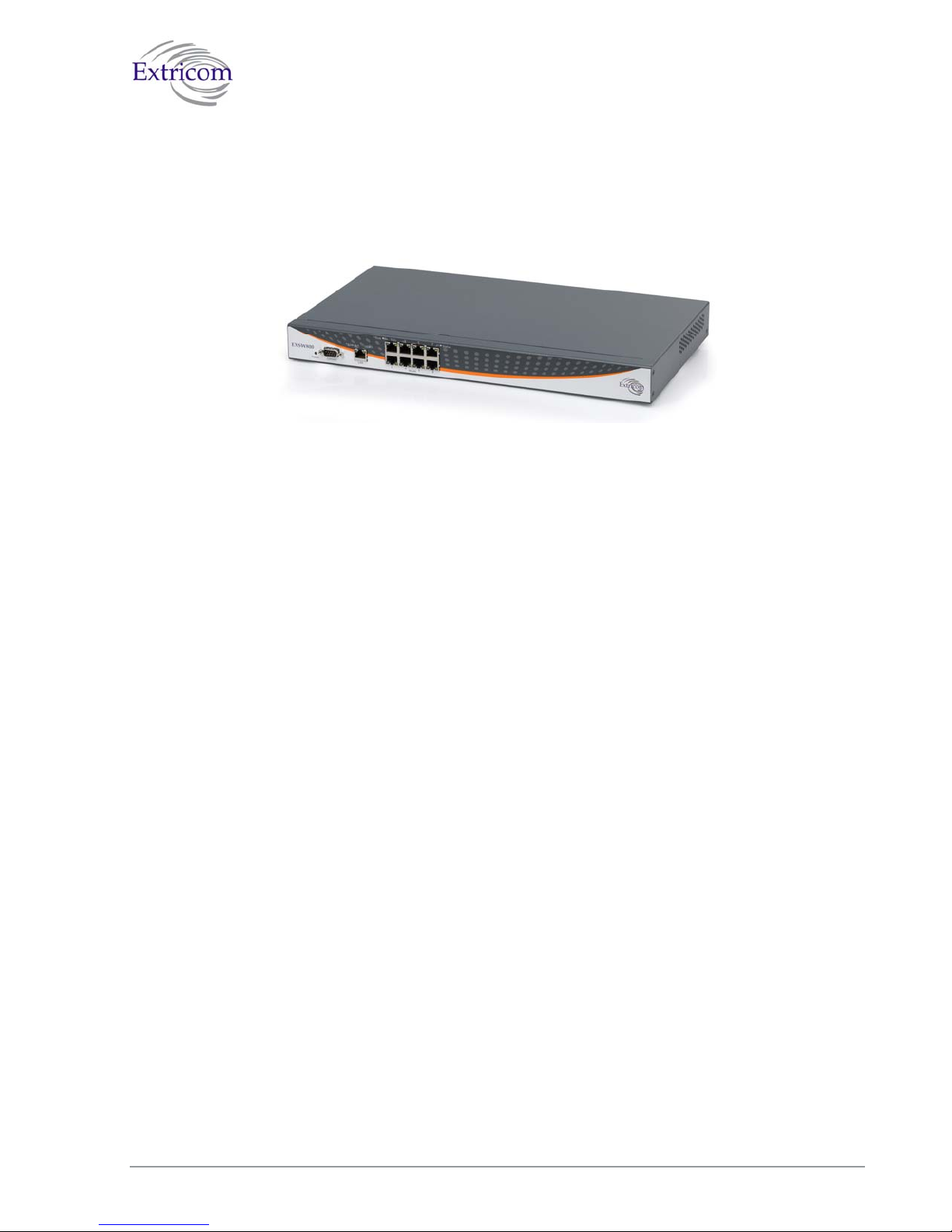
Figure 4. Extricom EXSW-800 Switch
Configuring a switch and its associated set of APs is as simple as configuring a single traditional
AP, greatly reducing the effort required to deploy and maintain the WLAN.
The minimal configuration required for the switch is done via a dedicated secured Web interface.
8 Introduction to the Extricom Wireless LAN System
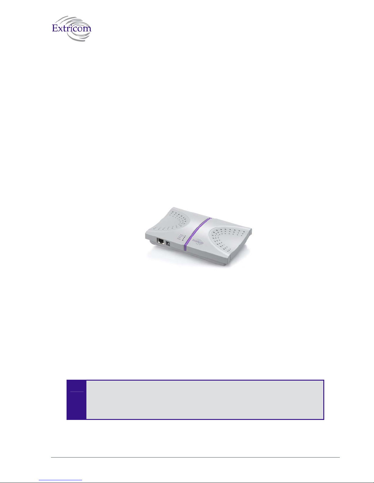
Overview of the Extricom Access Point
Extricom’s EXRP-20, EXRP-20D and EXRP-40 UltraThin APs are high-bandwidth devices,
containing standard 802.11 radio devices. The EXRP-20 and EXRP-20D contain two radio devices
while the EXRP-40 contains four radio devices
Since the APs have no software, they require no configuration. This makes them fully
interchangeable, enabling truly plug-and-play installation. If stolen, the APs do not pose a security
risk, since all encryption is performed in the switch.
With all intelligence residing in the WLAN switch, APs may be placed as close together as
necessary to provide high-quality, high-speed connectivity from all locations within the enterprise.
APs are connected to the Extricom WLAN Switch via standard Cat5e/6 cables. Since the APs are
powered by the standard 802.3af Power over Ethernet (PoE), only a single Cat5e/6 cable connection
is required to support two simultaneous radios.
"
Figure 5. Extricom EXRP-20 AP
Current software version on the WLAN switch only support two channel blankets, as
such when the EXRP-40 is connected, only two radio devices on this access point
will operate. Future versions will support full configuration
Extricom APs only function when they are directly connected to Extricom switches.
The Extricom WLAN System User Guide 9
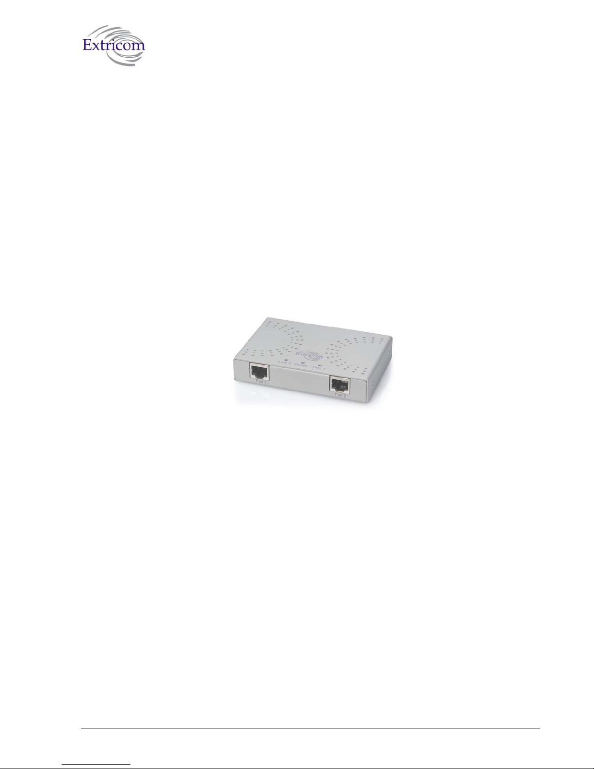
Overview of the Extricom Repeater
The EXRE-10 Power Over Ethernet (PoE) Range Extender is a unique product that doubles the
standard range of PoE, from the baseline 100 meters to a full 200 meters. It can be used both as a
standalone to extend the reach of PoE installations that are limited power source UL approved, and
as a complement to Extricom’s award-winning Interference-Free™ Wireless LAN (WLAN)
System. When used in WLAN implementations, the EXRE-10 enables Extricom UltraThin™
Access Points to be connected using standard Cat5e/6 cable up to 200 meters from the Extricom
WLAN Switch.
Continuing Extricom’s tradition of deployment simplicity, the EXRE-10 PoE Range Extender sits
in-line on the Ethernet cable and does not require an external power feed. The Range Extender
receives its power from the original PoE injector in the switch or from a PoE injector/power supply,
while it simultaneously injects PoE to the extended cable
Figure 6 Extricom EXRE-10 PoE Range Extender
10 Introduction to the Extricom Wireless LAN System
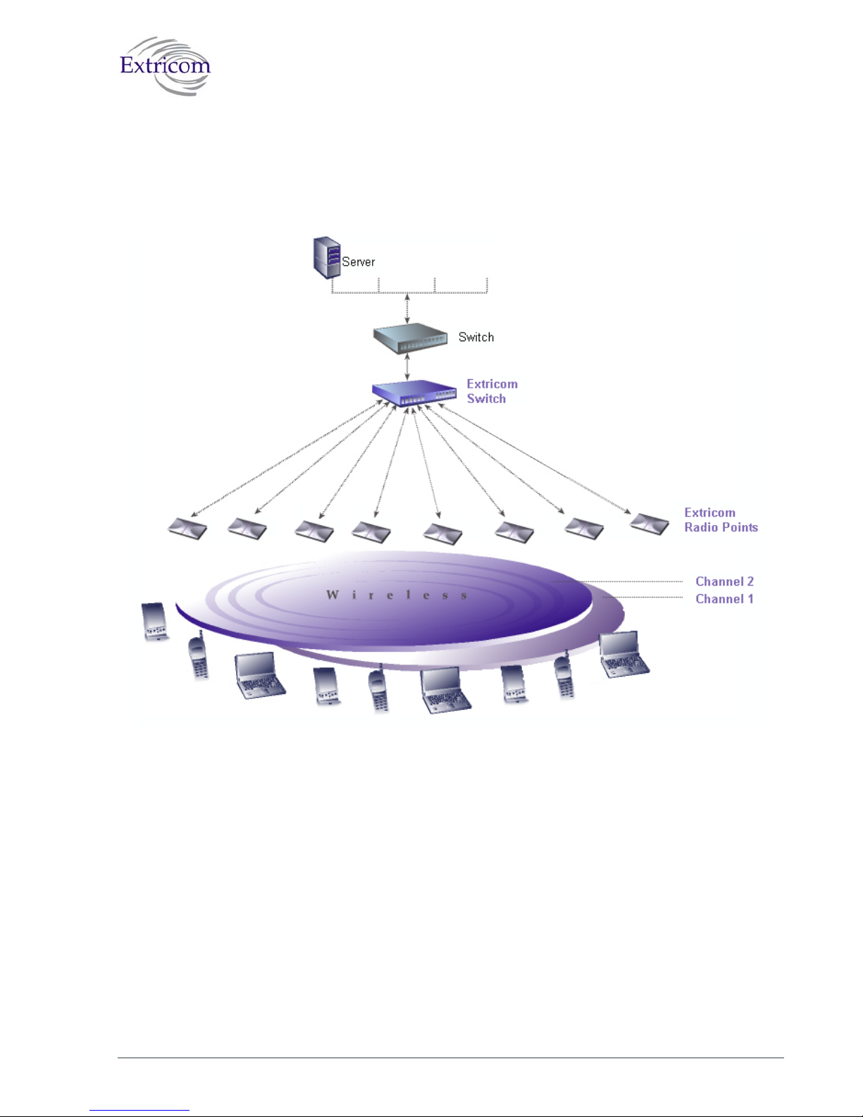
A Typical Extricom Wireless Network Topology
Extricom’s switch is connected to the wired LAN, and the APs spread throughout the enterprise.
Figure 7 displays a typical Extricom enterprise topology, consisting of an Extricom switch and
eight APs.
Extricom uses standard WLAN protocols (IEEE 802.11). As a result, any 802.11a/b/g standard
wireless device can work seamlessly with the Extricom system.
The Extricom WLAN System User Guide 11
Figure 7. Typical Extricom Typology


Chapter 2
Installing the Extricom WLAN System
This chapter provides instructions for unpacking and installing the Extricom WLAN system.
Unpacking the Extricom WLAN System
The Extricom WLAN system is shipped with the following:
z One Extricom switch.
z CD which contains The Extricom WLAN System User Guide and Release Notes.
z APs (the number of APs is based on customer order and provided in separate boxes) are
shipped as part of the overall order.
Additional Equipment Needed (Not Provided By
Extricom)
The following additional equipment is required for installing the Extricom WLAN system:
z One CAT-5e/6 cable for each AP.
z One CAT-5e/6 cable for connecting the WLAN switch uplink to the LAN switch.
z Two stainless steel pan head 8x1-1/4" self-tapping Phillips screws for mounting each AP
(optional).
z One power cable - For connecting power to the switch, use an AC power supply cord that
has a standard plug (according to country’s local specific regulations) and a C-13 connector
that conforms to the following minimal requirements:
z Approx. AWG: 16
z Strand 31/32
z Power Rating: 10 A
Use of a poorly grounded or ungrounded power cable may damage the switch.
-
The Extricom WLAN System User Guide 13
Determining the Location of the Extricom Access
Points
Before installing the switch and access points, plan the placement of the APs. Before permanently
mounting the APs, it is recommended to test the network (using a laptop client) to identify potential
coverage holes. If such a problem exists, relocate an AP or add additional APs to resolve the
coverage hole.
The APs should be placed in a stable, secure location, such as on top of a closet or bookshelf, or
mounted on a wall.
The switch should be placed near the distribution point of the LAN line. This is usually in the
communications closet of your enterprise.
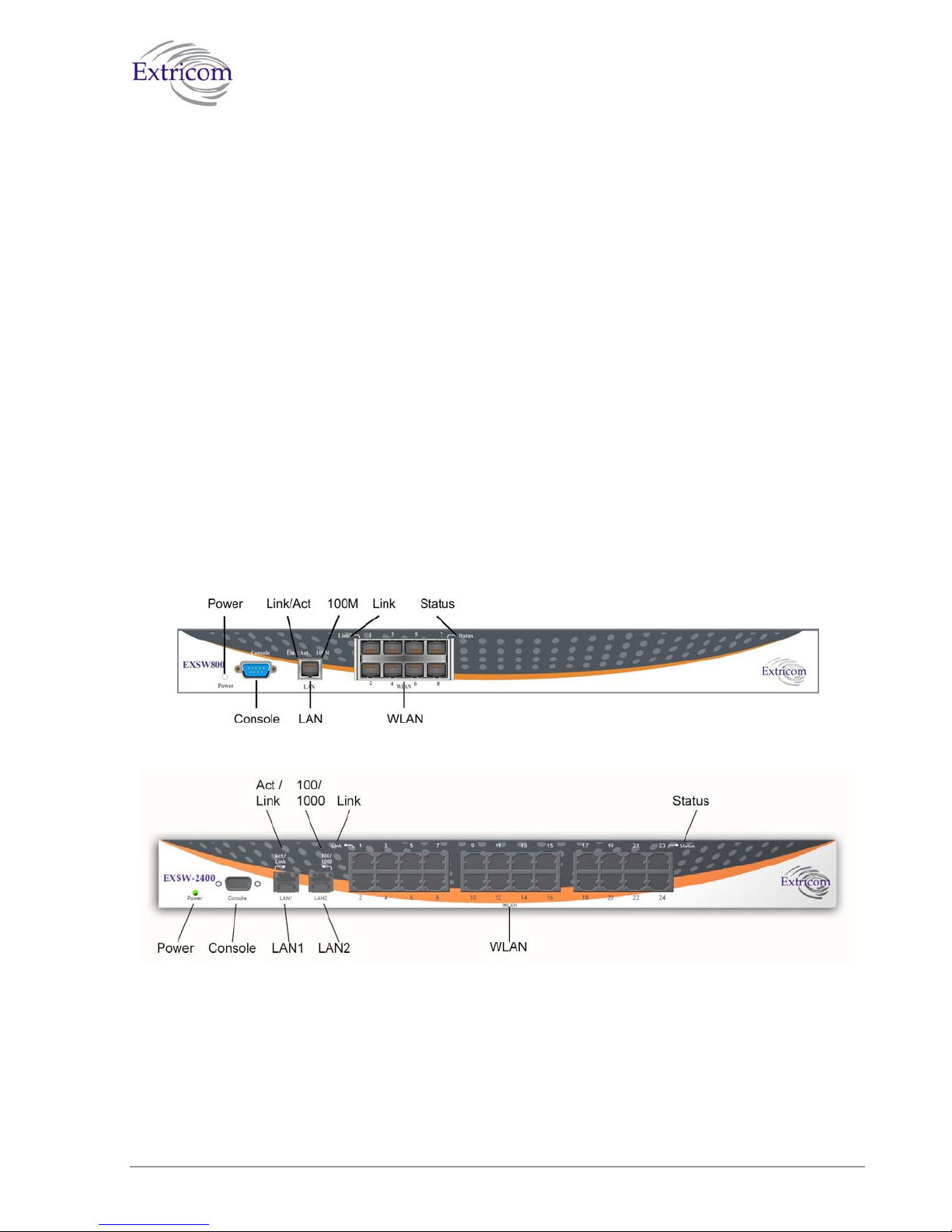
The Extricom EXSW-800/1200/2400 Switch
The Extricom EXSW-800 switch has 10 connectors and 4 LED types on the front panel (refer to
Figure 6).
The Extricom EXSW-2400 switch has 27 connectors and 4 LED types on the front panel (refer to
Figure 9).
Figure 8. Extricom EXSW-800 Switch
Figure 9. Extricom EXSW-2400 Switch
Table 1 describes the front panel and connectors of Extricom EXSW-800/2400 switches.
14 Installing the Extricom WLAN System

Table 1. Extricom EXSW-800/1200/2400 Switch Connectors
Connectors Description
Console
Serial connector – only to be used by, or as instructed by Extricom
personnel for troubleshooting, support, or maintenance. Can be
accessed using a Null modem cable.
EXSW-800
LAN
EXSW1200/2400
LAN1, LAN2
RJ-45 connectors – used to connect the switch to the wired LANs. On
EXSW-1200/2400 these connectors provide redundancy and load
sharing between them.
LAN2 is not currently active pending future development.
"
WLAN RJ-45 connectors – used to connect Extricom APs to the switch.
Do not connect any device other than Extricom APs to
-
the WLAN ports.
These ports provide 802.3AF PoE compatible power.
Maximum current: 270 mA, 48 volts.
Table 2 describes the front panel LEDs of Extricom EXSW-800/1200/2400 switches.
Table 2. Extricom EXSW-800/1200/2400 Switch LEDs
LEDs Color Description
Power Green On/off
LAN, LAN1, LAN2
Link/Act Green
EXSW-800
Orange
100M
EXSW-
Orange
1200/2400
100/1000
z On indicates connection to the LAN network
z Blinking indicates activity in the LAN network connection
z Off indicates no connection to the LAN network
z On – 100Mbps full duplex
z Off – 10Mbps
z On – 100Mbps full duplex
z
Blinking – 1000Mbps full duplex
1000Mbps is not currently active pending future
"
development.
WLAN
Link Green
z On indicates connection to the WLAN AP
z Blinking indicates activity over the connection to the WLAN
AP
z Off indicates no connection to the WLAN AP
The Extricom WLAN System User Guide 15
 Loading...