


USB 2.0 RG2311
1-port USB 2.0 100m CAT 5e/6/7 Extender System
with Flexible Power
User Guide

Thank you for purchasing the USB 2.0 RG2311.
Please read this guide thoroughly.
This document applies to, but is not limited to, Part Numbers: 01-00580, 01-00581, 01-00582, 01-00583 and
01-00584.
FCC Radio Frequency Interference Statement Warning
This device complies with Part 15 of the FCC rules. Operation is subject to the following two conditions: (1)
this device may not cause harmful interference, and (2) this device must accept any interference received
including interference that may cause undesired operation.
CE Statement
We, Icron Technologies Corporation, declare under our sole responsibility that the USB 2.0 RG2311, to which
this declaration relates, is in conformity with European Standard EN 55022, EN 61000, and EN 55024.
IC Statement
This Class A digital apparatus complies with Canadian ICES-003.
WEEE Statement
The European Union has established regulations for the collection and recycling of all waste electrical
and electronic equipment (WEEE). Implementation of WEEE regulations may vary slightly by individual EU
member states. Please check with your local and state government guidelines for safe disposal and recycling
or contact your national WEEE recycling agency for more information.
Product Operation and Storage
Please read and follow all instructions provided with this product, and operate for intended use only.
Do not attempt to open the product casing as this may cause damage and will void warranty. Use only
the power supply provided with this product. When not in use, product should be stored in a dry location
between -20°C and 70°C.
©2017 All rights reserved.
Document # 90-01515-A01

Contents
Introduction ........................................................................................................................ 3
USB 2.0 RG2311 Product Contents ............................................................................................................................................. 3
Requirements .................................................................................................................................................................................... 3
Features ............................................................................................................................................................................................... 3
The Local Extender .......................................................................................................................................................................... 4
The Remote Extender .................................................................................................................................................................... 5
Installation Guide ............................................................................................................... 6
Mounting the Local Extender or Remote Extender ............................................................................................................. 6
Preparing for Installation ............................................................................................................................................................... 6
Installing the Local Extender ....................................................................................................................................................... 7
Installing the Remote Extender .................................................................................................................................................. 7
Installing Flexible Power ............................................................................................................................................................... 7
Connecting the Local Extender to the Remote Extender .................................................................................................. 7
Connecting a USB Device ............................................................................................................................................................. 7
Checking the Installation .............................................................................................................................................................. 8
Compatibility ..................................................................................................................................................................................... 8
Troubleshooting ................................................................................................................. 9
Contacting Technical Support ........................................................................................... 11
Technical Glossary .............................................................................................................. 12
Specifications ...................................................................................................................... 13

Introduction
The instructions in this guide assume a general knowledge of computer installation procedures, familiarity
with cabling requirements, and some understanding of USB devices.
note
Notes provide additional information that could be useful.
Caution symbols are followed by very important information about an operational requirement.
USB 2.0 RG2311 Product Contents
Your RG2311 is packaged with:
• Local Extender
• Remote Extender
• International AC Power Adapter
• Country Specific Power Cord
• USB 2.0 Cable
• Quick Start Guide and Warranty Information
The RG2311 provides the option to apply power at the local extender or remote extender. The supplied 24V, 1A power
note
adapter can be connected to either the local or remote extender for normal operation. This option gives added
flexibility/convenience for installers to carry one product for multiple customers.
NEVER power BOTH the local and remote extenders at the same time.
Requirements
To complete the installation, you will also require the following items that are not included with the product:
• USB 1.1 or 2.0 compatible computer (host computer) with a USB compliant operating system
• USB 1.1 or 2.0 compatible device(s)
• CAT 5e/6/7 solid core Unshielded Twisted Pair (UTP) cable with two RJ45 connectors (if using surface
cabling), or CAT 5e/6/7 cabling with two information outlets and two CAT 5e/6/7 patch cords with
RJ45 connectors (if using premise cabling)
Features
The USB 2.0 RG2311 enables users to extend beyond the standard 5m cable limit for USB peripheral devices.
With the RG2311, USB device(s) can be located up to 100 meters (330 feet) from the computer. The RG2311 is
composed of two individual units: the local extender and remote extender.
The local and remote extenders may be hot to the touch during operation.
The RG2311 includes the ExtremeUSB® suite of features:
• Transparent USB extension
• True plug and play; no software drivers required
• Works with all major operating systems: Windows®, macOS™ and Linux®
3
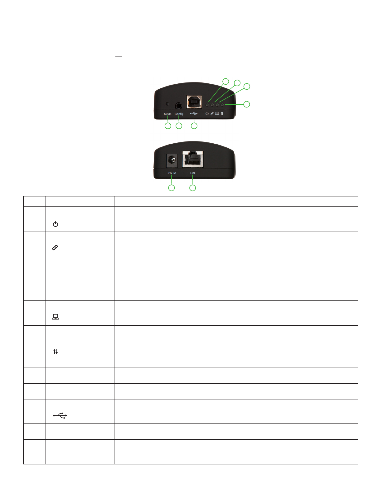
The Local Extender
The local extender connects to the computer using a standard USB cable (included). Power for the local
extender is provided by the host computer. Power for the remote extender is provided by the 24V AC adapter
connected at either the local or remote extender. The local extender delivers power over the CAT 5e/6/7
extension link to the remote extender when the included power supply is connected to the local extender.
Front View
765
Rear View
1
2
3
4
8
9
ITEM TYPE DESCRIPTION
1 Power LED (Green) LED turns on when power is supplied.
LED is off when no power is supplied by the host computer.
2 Link LED (Green) Indicates a valid ExtremeUSB link is established between the local and
remote extenders.
LED turns on when link between the local and remote extenders is
established.
LED is off when there is no link between the local and remote extenders.
LED is slow blinking when the unit is attempting to establish a link.
LED is fast blinking to indicate the unit is in Pairing Mode.
3 Host LED (Green) Indicates that the extender system is properly enumerated on the host
computer. LED blinks when the extender system is in a suspended state.
4 Activity LED
(Green)
Indicates data transmission is occurring between the local and remote
extenders.
LED blinks intermittently with or without a USB device connected.
When the local and remote extenders are in suspend mode, the LED is off.
5 Mode Reserved for manufacturer use.
6 Config Port Reserved for manufacturer use.
7 USB Host Port Used to connect the local extender to the host computer.
Accepts USB Type B connector.
8 Power Port Connects to the AC power supply.
9 Link Port (RJ45) Accepts RJ45 connector for CAT 5e/6/7 cabling to connect the local
extender to the remote extender.
4

The Remote Extender
The remote extender provides a USB Type A port for connecting standard USB devices. The remote extender
allows you to connect one USB device directly. Additional devices may be connected by attaching USB hubs
to the remote extender. The remote extender is powered either directly by the included power supply, or via
the CAT 5e/6/7 link extension cable from the local extender. The USB port delivers up to 1 Amp of current to
the attached USB device.
Front View
5
Rear View
1
2
3
4
6
7 8 9
ITEM TYPE DESCRIPTION
1 Power LED (Green) LED turns on when power is supplied.
2 Link LED (Green) Indicates a valid ExtremeUSB link is established between the local and
remote extenders.
LED turns on when link between local and remote extenders is
established.
LED is off when there is no link between the local and remote extenders.
LED is slow blinking when the unit is attempting to establish a link.
LED is fast blinking to indicate the unit is in Pairing Mode.
3 Host LED (Green) Indicates that the extender system is properly enumerated on the host
computer. LED blinks when the extender system is in a suspended state.
4 Activity LED
(Green)
Indicates data transmission is occurring between the local and remote
extenders.
LED blinks intermittently with or without a USB device connected.
When the local and remote extenders are in suspend mode, the LED is off.
5 USB Device Port Accepts USB device using Type A connector.
6 Power Port Connects to the AC power supply.
7 Link Port (RJ45) Accepts RJ45 connector for CAT 5e/6/7 cabling to connect the local
extender to the remote extender.
8 Config Port Reserved for manufacturer use.
9 Mode Reserved for manufacturer use.
5

Installation Guide
Connect the provided power adapter to either the local or remote extender.
Host Computer
Up to 100m between extenders over CAT 5e/6/7
Power can be supplied to either
Local Extender or Remote Extender
Local Extender
Remote Extender
All USB Devices
Mounting the Local Extender or Remote Extender
If mounting is required, the local and remote extenders have two mounting slots on each side for use with
cable tie/zap straps (not included).
mounting slot
Preparing for Installation
Before you can install the RG2311, you need to prepare your site:
1. Determine where the computer is to be located and set up the computer.
2. Determine where you want to locate the USB device(s).
3. If you are using surface cabling, the RG2311 supports a maximum distance of 100m.
OR
If you are using premise cabling, ensure CAT 5e/6/7 cable is installed between the two locations, with
CAT 5e/6/7 information outlets located near both the computer and the USB device(s), and the total
length, including patch cords is no more than 100m.
6

Installing the Local Extender
1. Place the local extender near the computer.
2. Install the supplied USB cable between the local extender and USB port on the host computer.
Installing the Remote Extender
1. Place the remote extender near the USB device(s) in the desired remote location.
Installing Flexible Power
1. Connect 24V 1A supplied AC power adapter to the local extender or remote extender, based on
installation requirement.
Use only the AC adapter supplied with the RG2311. Use of substitute adapters may cause permanent damage
to the system and will void the warrantly.
NEVER plug a power adapter to BOTH local and remote extenders, as this may cause permanent damage to the
system and will void the warranty.
Connecting the Local Extender to the Remote Extender
note
With Surface Cabling:
With Premise Cabling:
To ensure proper operation, it is recommended that only solid core CAT 5e/6/7, Unshielded Twisted Pair (UTP) cabling
be used to connect the local extender to the remote extender. The cabling must have a straight-through conductor
configuration with no crossovers and must be terminated with 8 conductor RJ45 connectors at both ends. The combined
length of any patch cords using stranded conductors must not exceed 100m.
1. Plug one end of the CAT 5e/6/7 cabling (not included) into the Link port (RJ45) on the local extender.
2. Plug the other end of the CAT 5e/6/7 cabling into the Link port (RJ45) on the remote extender.
1. Plug one end of a CAT 5e/6/7 patch cord (not included) into the Link port (RJ45) on the local extender.
2. Plug the other end of the patch cord into the CAT 5e/6/7 information outlet near the host computer.
3. Plug one end of the second CAT 5e/6/7 patch cord (not included) into the Link port (RJ45) on the
remote extender.
4. Plug the other end of the second patch cord into the CAT 5e/6/7 information outlet near the USB
device.
Connecting a USB Device
1. Install any software required to operate the USB device(s). Refer to the documentation for the USB
device(s), as required.
2. Connect the USB device to the device port on the remote extender.
3. Check that the device is detected and installed properly in the operating system.
7

Checking the Installation
1. On the local and remote extenders, check that the Power, Activity, Link and Host LEDs are on. If the Host
or Link LEDs are permanently off, then the cabling between the local and remote extenders may not be
installed properly or is defective.
2. For Windows users (XP, 7, 8, 8.1, 10), open Device Manager to confirm that the RG2311 extender system
has been installed correctly. Expand the entry for Universal Serial Bus controllers by clicking the “+” sign. If
the extender system has been installed correctly, you should find it listed as a “Generic USB Hub”.
note
note
note
To open Device Manager in Windows XP:
Right click “My Computer” then select: Properties >> Hardware tab >> Device Manager
To open Device Manager in Windows 7:
Open the Start Menu, right click on “Computer” then select: Manage >> Device Manager
To open Device Manager in Windows 8, 8.1 or 10:
Right click the Start Menu and then select: Device Manager
3. For macOS users, open the System Profiler to confirm that the RG2311 Series extender system has
installed correctly. In the left hand column under Hardware, select “USB” and inspect the right hand panel.
If the extender has been installed correctly, you should find it listed as a “Hub” under the USB High-Speed
Bus/USB Bus.
note
To open System Profiler in macOS:
Open the Finder, select Applications, then open the Utilities folder and double click on the System Profiler icon.
4. If the RG2311 Series extender system is not detected correctly or fails to detect, please consult the
Troubleshooting section in this guide.
Compatibility
The RG2311 complies with USB 1.1 and USB 2.0 specifications governing the design of USB devices. However,
there is no guarantee that all USB devices will be compatible, as there are a number of different factors that
may impact the operation of USB devices over extended distances.
8

Troubleshooting
The following table provides troubleshooting tips. The topics are arranged in the order in which they should
be executed in most situations. If you are unable to resolve the problem after following these instructions,
please contact Technical Support for further assistance.
PROBLEM CAUSE SOLUTION
USB device is
attached but
not functioning.
• The USB device requires drivers
that were not installed.
• The USB device does not
support USB hubs.
1. Install the required USB device driver on the
computer operating system prior to attaching
the USB device into the remote extender. Please
see your USB device manufacturer’s website for
details.
USB device is
attached but
not functioning.
• The USB device has
malfunctioned.
• Overcurrent condition has
occurred because the USB
device has drawn more current
than can be supplied per USB
specification (1A). Operating
system may generate a status
bubble indicating an issue.
2. In the Universal Serial Bus controllers section of
Device Manager, check that the USB device has
enumerated.
3. Contact Technical Support for assistance.
1. Power cycle remote extender by unplugging
the power adapter from the extender. Wait
approximately 30 seconds and then plug the
power adapter back into the remote extender.
2. If overcurrent continues to occur, either:
(a) the USB device may use more power than the
USB specification, or (b) the USB device may be
damaged.
3. Consult your USB device documentation and
power your USB device with the required power
supply.
Link LED
on the local
and remote
extenders blink
intermittently.
• The CAT 5e/6/7 cable
connecting the local and remote
extenders is faulty.
1. Ensure the CAT 5e/6/7 cable is of decent quality.
2. Contact Technical Support for assistance.
9

PROBLEM CAUSE SOLUTION
Link LED on the
local and remote
• The remote extender is not
receiving power.
1. Confirm the host computer is on and providing
power to local extender.
extenders is off.
• The local extender is not
receiving power.
• The link cable is
malfunctioning.
• The extender system is
malfunctioning.
2. Ensure the supplied AC power adapter is properly
connected to either the local or the remote
extender.
3. Ensure the CAT 5e/6/7 cabling between the local
and remote extenders is properly installed or
replace the link cable.
4. Check that the AC adapter is connected to a live
source of electrical power.
5. Contact Technical Support for assistance.
10

Contacting Technical Support
If you are experiencing problems not referenced in the Troubleshooting Guide, contact Technical Support at
the company where you purchased this product and provide them with the following information:
• Host computer make and mode
• Type of operating system installed (e.g. Windows 10, macOS 10.12, etc.)
• Part number and serial number of both the Local Extender and Remote Extender unit
• Make and model of any USB device(s) attached to the product
• Description of the installation
• Description of the problem
11

Technical Glossary
Category 5e/6/7 (CAT 5e/6/7) Network Cabling
Category 5e/6/7 cable is commonly also referred to as CAT 5e or CAT 6 or CAT 7. This cabling is available
in either solid or stranded twisted pair copper wire variants and as UTP (Unshielded Twisted Pair) or STP
(Shielded Twisted Pair). UTP cables are not surrounded by any shielding making them more susceptible
to Electromagnetic Interference (EMI). STP cables include shielding the copper wires and provide better
protection against EMI.
USB 2.0 Cables
USB 2.0 cables have two distinct full-sized connectors. The Type A connector is used to connect the cable
from a USB device to the Type A port on a computer or hub. The Type B connector is used to attach the USB
cable to a USB device.
RJ45
USB Type A
Port
USB Type A
Connector
USB Type B
Port
USB Type B
Connector
The Registered Jack (RJ) physical interface is what connects the network cabling (CAT 5e/6/7) to the local
and remote extenders. You may use either the T568A scheme (Table 1) or the T568B scheme (Table 2) for
cable termination as the Ranger 2311 requires all four pairs of the cable. RJ45 connectors are sometimes also
referred to as 8P8C connectors. Note that any give cable must be terminated using the same T568 scheme
on both ends to operate correctly.
RJ45 Pin Positioning
Table 1 - T568A Wiring Table 2 - T568B Wiring
PIN PAIR WIRE CABLE COLOR PIN PAIR WIRE CABLE COLOR
1 3 1 WHITE/GREEN 1 2 1 WHITE/ORANGE
2 3 2 GREEN 2 2 2 ORANGE
3 2 1 WHITE/ORANGE 3 3 1 WHITE/GREEN
4 1 2 BLUE 4 1 2 BLUE
5 1 1 WHITE/BLUE 5 1 1 WHITE/BLUE
6 2 2 ORANGE 6 3 2 GREEN
7 4 1 WHITE/BROWN 7 4 1 WHITE/BROWN
8 4 2 BROWN 8 4 2 BROWN
Pair 2
Pair 3Pair 1
Pair 4
Pair 3Pair 1
Pair 2
Pair 4
1 2
W-G G W-O BL W-BL O W-BR BR
3
4 5
6
7 8
1 2
W-O O W-G
3
4 5
B W-BL G W-BR
6
7 8
BR
12

Specifications
Range Up to 100m (330ft) over Cat 5e/6/7 cable
High-speed devices (480 Mbps) (USB 2.0)
USB Device Support
Full-speed devices (12 Mbps) (USB 1.1)
Low-speed devices (1.5 Mbps) (USB 1.1)
Maximum USB Devices
Supported
30 USB devices or 4 USB hubs with 26 USB devices.
Power Supply 100-240 V AC input, 24V 1A DC output
AC Adapter Connector 2.1 mm centre-positive jack
Current Available to USB
Device at Remote Extender
Mounting Slots for Cable Ties
Enclosure Material
Up to 1 Amp
Black ABS with Rubberized Coating
System Shipping Weight 0.642 kg (1.416 lbs.)
LOCAL EXTENDER
USB Connector 1 x USB 2.0 Type B
Link Connector 1 x RJ45
Dimensions 65.0mm x 87.5mm x 30.0mm (2.6” x 3.4” x 1.2”)
REMOTE EXTENDER
USB Connector 1 x USB Type A
Link Connector 1 x RJ45
Dimensions 65.0mm x 87.5mm x 30.0mm (2.6” x 3.4” x 1.2”)
ENVIRONMENTAL
Operating Temperature Range 0°C to 50°C (32°F to 122°F)
Storage Temperature Range -20°C to 70°C (-4°F to 158°F)
Operating Humidity 20% to 80% relative humidity, non-condensing
Storage Humidity 10% to 90% relative humidity, non-condensing
COMPLIANCE
EMC FCC (Class A), CE (Class A)
Environmental RoHS2 (CE)
Safety
Flammability V-0
SUPPORT
Warranty 2-year
13
 Loading...