

Extreme USB RG2304N, RG2304GE-LAN User Manual
USB 2.0 RG2304N/RG2304GE-LAN
4-Port USB 2.0 Gigabit Ethernet LAN
Extender Systems
User Guide

Thank you for purchasing the USB 2.0 RG2304N/2304GE-LAN.
Please read this guide thoroughly.
This document applies to Part Numbers: 01-00453, 01-00454, 01-00455, 01-00456, 01-00529, 01-00609,
01-00610, 01-00611, 01-00612, 01-00613, 02-00030, 02-00031, 02-00117 and 02-00118.
FCC Radio Frequency Interference Statement Warning
This device complies with Part 15 of the FCC rules. Operation is subject to the following two conditions:
(1) this device may not cause harmful interference, and (2) this device must accept any interference received
including interference that may cause undesired operation.
CE Statement
We declare under our sole responsibility that the USB 2.0 RG2304 Series, to which this declaration relates, is
in conformity with European Standard EN 55022, EN 61000 and EN 55024.
IC Statement
This Class B digital apparatus complies with Canadian ICES-003.
WEEE Statement
The European Union has established regulations for the collection and recycling of all waste electrical
and electronic equipment (WEEE). Implementation of WEEE regulations may vary slightly by individual EU
member states. Please check with your local and state government guidelines for safe disposal and recycling
or contact your national WEEE recycling agency for more information.
Product Operation and Storage
Please read and follow all instructions provided with this product, and operate for intended use only.
Do not attempt to open the product casing as this may cause damage and will void warranty. Use only
the power supply provided with this product. When not in use, product should be stored in a dry location
between -20°C and 70°C.
©2016 All rights reserved.
Document #90-01103-B04

Contents
Introduction .............................................................................................................3
RG2304N/2304GE-LAN Product Contents .................................................................................. 3
Features .................................................................................................................................................. 3
The Local Extender ............................................................................................................................. 4
The Remote Extender ........................................................................................................................ 5
Installation Guide ....................................................................................................6
Installing the RG2304N/2304GE-LAN System on a Local Area Network ......................... 6
Requirements ....................................................................................................................................... 6
Preparing your Network ................................................................................................................... 6
Preparing Your Site ............................................................................................................................. 7
Installing the Local Extender .......................................................................................................... 7
Installing the Remote Extender ..................................................................................................... 7
Installing the RG2304N/2304GE-LAN System as Direct Connect....................................... 8
Requirements ....................................................................................................................................... 8
Preparing Your Site ............................................................................................................................. 8
Installing the Local Extender .......................................................................................................... 9
Connecting the Local Extender to the Remote Extender .................................................... 9
Installing the Remote Extender ..................................................................................................... 9
Checking the Installation ................................................................................................................10
Connecting a USB Device ............................................................................................................... 11
Pairing the Local and Remote Extender .................................................................................... 11
Unpairing an Extender ....................................................................................................................11
Compatibility ......................................................................................................................................11
USB Extender Mounting Options .........................................................................12
Option 1: USB Extender Mounting Kit ....................................................................................... 12
Option 2: USB Extender Direct Surface Mounting ................................................................ 13
Troubleshooting ....................................................................................................14
Contacting Technical Support ..............................................................................16
Technical Glossary .................................................................................................17
Specifications.........................................................................................................18
Introduction
This guide provides product information for the RG2304N/2304GE-LAN, installation instructions and
troubleshooting guidelines. The instructions in this guide assume a general knowledge of computer
installation procedures, familiarity with cabling requirements and some understanding of USB devices.
note
NOTE: Notes provide additional information that could be useful.
CAUTION: Cautions provide important information about an operational requirement.
RG2304N/2304GE-LAN Product Contents
Your extender system is packaged with:
• LocalExtender
• RemoteExtender
• USB2.0Cable
• RemoteExtenderACInternationalPowerAdapter
• Country Specific Power Cable
• Quick Start Guide
Features
The RG2304N/2304GE-LAN incorporates ExtremeUSB® technology, enabling users to extend USB beyond the
standard 5m cable limit for USB 2.0 peripheral devices. This extender system is composed of two individual
units: the Local Extender and the Remote Extender and has the following key features:
• 100mofextensionwhendirectlyconnectedoverCAT5e/6/7
• USBextensionoveraGigabitEthernetLocalAreaNetwork(LAN)
• SupportfornewUSB3.0hostcontrollersanddevices
• SupportforallUSBdevicetypes
The RG2304N/2304GE-LAN includes the ExtremeUSB® suite of features:
• Transparent USB extension
• True plug and play; no software drivers required
• Works with all major operating systems: Windows®, OS X® and Linux®
USB 3.0 devices will perform at USB 2.0 speeds if extended through the RG2304N/2304GE-LAN.
note
3
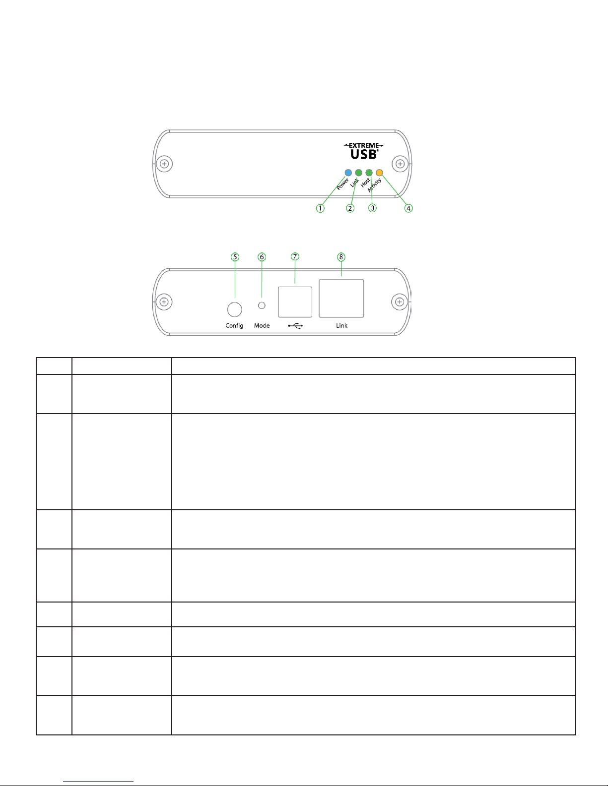
The Local Extender
The local extender unit connects to the computer using a standard USB 2.0 cable. Power for this unit is
provided by the host computer.
Front View
Rear View
ITEM TYPE DESCRIPTION
1
Power LED
(Blue)
LED turns on when power is supplied.
LED is off when no power is supplied by the host computer.
Link LED (Green) Indicates a valid ExtremeUSB link is established between the local and remote
extender.
2
LED turns on when link between local and remote extender is established.
LED is off when there is no link between local and remote extenders.
LED is slow blinking when the unit is attempting to establish a link.
LED is fast blinking to indicate the unit is in Pairing Mode.
3
4
Host LED
(Green)
Activity LED
(Amber)
Indicates that the extender system is properly enumerated on the host
computer. The LED blinks when the extender is in a suspended state.
Indicates data transmission is occurring between local and remote extenders.
LED blinks intermittently with or without a USB device connected.
When the local and remote extenders are in suspend mode, the LED is off.
5 Config Reserved for manufacturer use.
6
Mode
Used to establish a paired connection between local and remote extenders.
USB Host Port Used to connect the local extender to the host computer. Accepts Type B
7
Link Port (RJ45) Accepts RJ45 connector for CAT 5e/6/7 cabling to connect the local extender
8
connector into the local extender.
to the remote extender unit.
4
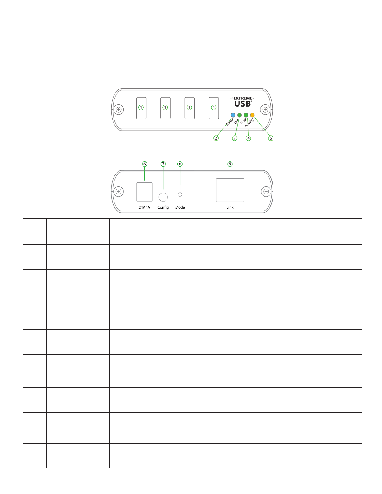
The Remote Extender
The remote extender unit provides USB Type A ports for standard USB devices and allows you to connect
up to four USB devices directly. Additional devices may be connected by attaching up to four USB hubs to
the remote extender unit. The remote extender is powered by an external AC adapter and can supply up to
600mA to each USB port when all four ports are used concurrently; 1A per port when two or less are being
used.
Front View
Rear View
ITEM TYPE DESCRIPTION
1 USB Device Ports Accepts USB device(s) using Type A connectors.
2 Power LED (Blue) LED turns on when power is supplied.
LED is off when no power is supplied by the host computer.
3 Link LED (Green) Indicates a valid ExtremeUSB link is established between the local and remote
extender.
LED turns on when link between local and remote extender is established.
LED is off when there is no link between local and remote extenders.
LED is slow blinking when the unit is attempting to establish a link.
LED is fast blinking to indicate the unit is in Pairing Mode.
4 Host LED (Green) Indicates that the extender system is properly enumerated on the host
computer. The LED blinks when the extender is in a suspended state.
5 Activity LED
(Amber)
Indicates data transmission is occurring between local and remote extenders.
LED blinks intermittently with or without a USB device connected.
When the local and remote extenders are in suspend mode, the LED is off.
6 Power Port Connects to the AC power supply. Required at the remote extender for proper
operation.
7 Config Reserved for manufacturer use.
8 Mode Used to establish a paired connection between local and remote extenders.
9 Link Port (RJ45) Accepts RJ45 connector for CAT 5e/6/7 cabling to connect the local extender
to the remote extender unit.
5
 Loading...