

EXTREME SWITCHING ERS 3500, ERS 3510GT, ERS 3510GT-PWR+, ERS 3600 Series, ERS 3626GTS-PWR+ Series Manual
Installation Job Aid for Ethernet Routing
Switch 3500 Series
NN47203-303
Issue 04.01
November 2017
Notices
Notice paragraphs alert you about issues that require your attention.
Following are descriptions of the types of notices used in this document.
Note:
Notes provide tips and useful information regarding the installation and operation of products.
Electrostatic alert:
ESD notices provide information about how to avoid discharge of static electricity and
subsequent damage to products.
Caution:
Caution notices provide information about how to avoid possible service disruption or damage to
products.
Warning:
Warning notices provide information about how to avoid personal injury when working with
products.
Voltage:
Danger—High Voltage notices provide information about how to avoid a situation or condition
that can cause serious personal injury or death from high voltage or electric shock.
Danger:
Danger notices provide information about how to avoid a situation or condition that can cause
serious personal injury or death.
©
2017, Extreme Networks, Inc.
All Rights Reserved. 1
Safety messages
Safety messages are an important part of the technical documentation. The messages alert you to
hazards to personnel and equipment and provide guidance for the safe operation of your equipment.
Failure to comply with the safety messages could result in equipment damage and personal injury.
Following are the most common types of safety messages.
Warning:
Installation must be performed by qualified personnel only. Read and follow all warning notices
and instructions marked on the product or included in the documentation.
Voltage:
This equipment relies on the building's installation for overcurrent protection. Ensure that a fuse
or circuit breaker no larger than 120 VAC, 15 A U.S. (240 VAC, 16 A International) is used on
the phase conductors.
Caution:
This device is a Class A product. In a domestic environment, this device can cause radio
interference, in which case the user may be required to take appropriate measures.
Caution:
When mounting this device in a rack, do not stack units directly on top of one another in the
rack. Each unit must be secured to the rack with appropriate mounting brackets. Mounting
brackets are not designed to support multiple units.
Voltage:
Use only power cords that have a grounding path. Without a proper ground, a person who
touches the switch is in danger of receiving an electrical shock. Lack of a grounding path to the
switch can result in excessive emissions.
Warning:
Disconnecting the power cord is the only way to turn off power to this device. Always connect
the power cord in a location that can be reached quickly and safely in case of an emergency.
Warning:
Fiber optic equipment can emit laser or infrared light that can injure your eyes. Never look into
an optical fiber or connector port. Always assume that fiber optic cables are connected to a light
source.
November 2017 Installation Job Aid for Ethernet Routing Switch 3500 Series 2
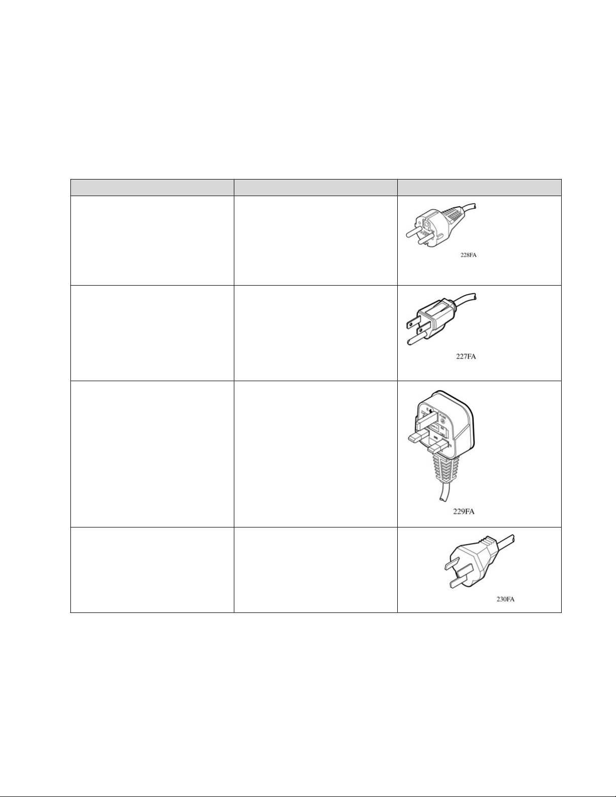
AC power cord specifications
Required cable: AC power cord that meets the requirements of your local electrical code. The
following table describes the International power cord specifications.
Table 1: International power cord specifications
Country and plug description Specifications Typical plug
Continental Europe
220 or 230 VAC
• CEE7 standard VII male plug
• Harmonized cord (HAR marking
on the outside of the cord jacket
to comply with the CENELEC
Harmonized Document HD-21)
U.S./Canada/Japan
• NEMA5-15P male plug
• UL-recognized (UL stamped on
cord jacket)
• CSA-certified (CSA label
secured to the cord)
United Kingdom
• BS1363 male plug with fuse
• Harmonized cord
50 Hz
Single phase
100 or 120 VAC
50-60 Hz
Single phase
240 VAC
50 Hz
Single phase
Australia
AS3112-1981 male plug
November 2017 Installation Job Aid for Ethernet Routing Switch 3500 Series 3
240 VAC
50 Hz
Single phase

Before you begin
Ensure the area where you install and use the switch meets the following environmental
requirements:
• Ambient temperature between 32°F and 122°F (0°C and 50°C).
• Relative humidity between 0% and 95% noncondensing.
• No nearby heat sources such as hot air vents or direct sunlight.
• No nearby sources of severe electromagnetic noise.
• No excessive dust.
• Adequate power source within six feet; one circuit required for each power supply.
• At least 2 inches (5.1 cm) (or one vertical rack width) on all sides of the switch unit for
ventilation.
• Adequate space at the front and rear of the switch for access to cables.
If you are installing a single Ethernet Routing Switch on a table or shelf, ensure the surface can
support at least 7 to 13 pounds (3 to 6 kilograms).
Installation preparation
To prevent damage, handle the switch carefully by using the following guidelines:
• To prevent damage from electrostatic discharge, always wear an antistatic wrist strap
connected to an ESD jack.
• Always place the switch on appropriate antistatic material.
• Support the switch from underneath with two hands. Do not touch components or connector
pins with your hand, or damage can result.
• Do not over tighten screws. Tighten until snug. Do not use a power tool to tighten screws.
For information about technical specifications for the individual switches, see Installing Ethernet
Routing Switch 3500 Series.
Installing the switch
The following procedures describe how to install an ERS 3500 series on a table or shelf, or in an
equipment rack.
November 2017 Installation Job Aid for Ethernet Routing Switch 3500 Series 4

Note:
The installation procedure for ERS 3510GT and ERS 3510GT-PWR+ is different from the other
switch models in the series. Refer to Installing an ERS 3510GT or ERS 3510GT-PWR+ switch
section for installation procedures for the switch models ERS 3510GT or ERS 3510GT-PWR+.
Installing an ERS 3500 Series in an equipment rack
This procedure describes how to install an ERS 3500 Series in an equipment rack using the
supplied brackets. The brackets secure the chassis and prevent it from sliding around during
vibration or when inserting or extracting transceivers.
Required tool: Phillips screwdriver for attaching brackets to the switch.
Rack requirements:
• Space of 2.8 inches (7.1 cm) (or one vertical rack width) for each switch in an E1A or 1EC 20
standard 19 inch (48.2 cm) equipment rack and T1A 23 inch (58.5 cm) equipment rack.
• Appropriate rack space to accommodate 1U switch height (44 mm).
• Rack bolted to floor and braced if necessary.
• Rack must be grounded to the same grounding electrode used by the power service in the
area. The group path must be permanent and must not exceed 1 Ohm of resistance from the
rack to the grounding electrode.
Bracket requirements: One Spare Rack Mount Kit — this kit can be used as a replacement rack
mount kit for the ERS switch and must be ordered separately.
Perform the following procedure to install your switch in an equipment rack.
Procedure
1. Ensure power is disconnected from the switch.
2. Attach a bracket to each side of the switch with the included screws.
November 2017 Installation Job Aid for Ethernet Routing Switch 3500 Series 5
 Loading...