

Extreme Networks Summit X450e, Summit X250e, Summit X450, Summit X450a, Summit X460 Hardware Installation Manual
...
Summit Family Hardware
Installation Guide
100286-00 Rev. 24

Copyright © 2014 Extreme Networks
100286-00 Rev. 24
Published July 2014
© 2013 Extreme Networks, Inc. All Rights Reserved.
Extreme Networks and the Extreme Networks logo are trademarks or registered trademarks of
Extreme Networks, Inc. in the United States and/or other countries.
Specifications are subject to change without notice.
All other registered trademarks, trademarks, and service marks are property of their respective
owners.
For additional information on Extreme Networks trademarks, please see:
www.extremenetworks.com/about-extreme/trademarks.aspx.
For information, contact:
Extreme Networks
Street Address (if required)
City (if required), State (if needed) Zip code (if required)
e-mail address (one or more)
www.extremenetworks.com

Table of Contents
Preface.........................................................................................................................................8
Audience................................................................................................................................................................................... 8
Conventions.............................................................................................................................................................................9
Related Publications..........................................................................................................................................................10
Chapter 1: Summit Family Switches....................................................................................... 11
Overview of the Summit Switches...............................................................................................................................11
Summit X150 Series Switches....................................................................................................................................... 16
Summit X250e Series Switches....................................................................................................................................21
Summit X350 Series Switches.....................................................................................................................................34
Summit X430 Series Switches.....................................................................................................................................39
Summit X440 Series Switches....................................................................................................................................44
Summit X450, X450a, and X450e Series Switches.......................................................................................... 67
Summit X460 Series Switches....................................................................................................................................90
Summit X480 Series Switches.................................................................................................................................... 99
Summit X650 Series Switches...................................................................................................................................105
Summit X670 Series Switches...................................................................................................................................109
Summit X770 Series Switches.....................................................................................................................................115
Pluggable Interfaces for Summit Family Switches............................................................................................119
Chapter 2: Summit Power Supplies.....................................................................................120
Power supply overview................................................................................................................................................. 120
External Power Supplies............................................................................................................................................... 120
Summit Replaceable Internal Power Supplies....................................................................................................133
Chapter 3: Summit Option Cards and Versatile Interface Modules................................137
Overview............................................................................................................................................................................... 137
Summit XGM-2xn Option Card..................................................................................................................................138
Summit XGM2-2xn Option Card................................................................................................................................139
Summit XGM2-2xf Option Card................................................................................................................................140
Summit XGM2-2sf Option Card..................................................................................................................................141
Summit XGM2-2bt Option Card................................................................................................................................. 141
Versatile Interface Modules for the Summit X650 Series Switches........................................................ 142
Versatile Interface Modules for the Summit X480 Series Switches........................................................145
Optional Ports for the Summit X460 Series Switches...................................................................................147
VIM4-40G4X Versatile Interface Module for the Summit X670 Switch................................................150
Chapter 4: Site Preparation.................................................................................................. 152
Planning Your Site............................................................................................................................................................ 152
Meeting Site Requirements..........................................................................................................................................153
Evaluating and Meeting Cable Requirements.....................................................................................................158
Meeting Power Requirements....................................................................................................................................163
Applicable Industry Standards...................................................................................................................................165
Chapter 5: Building Stacks....................................................................................................167
Building Stacks Overview.............................................................................................................................................167
Stacking Methods and Summit Switches............................................................................................................. 169
Stacking Cables................................................................................................................................................................. 174
Placing Summit Family Switches for Stacked Operation............................................................................. 175
Summit Family Hardware Installation Guide 3

Table of Contents
Using the SummitStack-V Feature...........................................................................................................................176
Connecting the Switches to Form the Stack Ring.......................................................................................... 180
Example SummitStack-V Feature............................................................................................................................ 193
Connecting Stacking Cables.......................................................................................................................................194
Connecting Console Ports for a Stack..................................................................................................................206
Management Port Cabling.......................................................................................................................................... 207
Stacking Port LEDs.........................................................................................................................................................207
Stack Number Indicator LEDs...................................................................................................................................207
Chapter 6: Installing Summit Family Switches................................................................. 208
Safety Information..........................................................................................................................................................209
Installing a Summit Family Switch (Models Other than Summit X430-8p, X460, X480, X650, X670 and X770 Series)
..................................................................................................................................................................................................209
Installing a Summit X460 Series Switch.............................................................................................................. 220
Installing a Summit X430-8p Series Switch........................................................................................................227
Installing AC Power Supplies in Summit X460 Series Switches.............................................................. 229
Installing a Model 10933 or 10934A 300 W DC Power Supply in a Summit X460 Series Switch
.................................................................................................................................................................................................. 234
Installing a Summit X480 Series Switch...............................................................................................................243
Installing Summit 450 W and 550 W Power Supplies................................................................................... 251
Installing a Summit X650 Series Switch................................................................................................................261
Installing Summit X650 Power Supplies..............................................................................................................268
Installing a Summit X670 or X770 Series Switch.............................................................................................276
Connecting Network Interface Cables..................................................................................................................284
Initial Management Access......................................................................................................................................... 285
Chapter 7: Installing Summit External Power Supplies................................................... 288
Safety.....................................................................................................................................................................................288
Pre-installation Requirements...................................................................................................................................289
Installing an EPS-160 External Power Module (with EPS-T)......................................................................290
Installing an EPS-LD External Power Supply.....................................................................................................292
Installing an EPS-500 External Power Supply Unit........................................................................................ 295
Installing an EPS-600LS External Power Module............................................................................................299
Installing an EPS-150DC External Power Module (with EPS-T2).............................................................303
Installing an EPS-C2 Chassis......................................................................................................................................308
Chapter 8: Installing Optional Ports....................................................................................317
Installing a Summit Port Option Card.....................................................................................................................317
Installing an Option Card in Slot B of a Summit X460 Series Switch.....................................................319
Installing a Versatile Interface Module in a Summit X480, X650, or X670 Series Switch............ 321
Chapter 9: Replacing AC Power Supplies in Summit Family Switches.........................323
Replacing a Summit 300 W AC Power Supply................................................................................................ 323
Replacing a Summit 450 W or 550 W AC Power Supply...........................................................................325
Replacing a Summit 750 W AC Power Supply.................................................................................................327
Replacing a Summit X850 W AC Power Supply.............................................................................................330
Removing EPS Series AC Redundant Power Supplies................................................................................. 332
Chapter 10: Replacing DC Power Supplies in Summit Family Switches....................... 334
Replacing a Summit 300 W DC Power Supply................................................................................................334
Replacing a Summit 450 W or 550 W DC Power Supply............................................................................341
Replacing a Summit 850 W DC Power Supply.................................................................................................347
Summit Family Hardware Installation Guide 4

Table of Contents
Removing an EPS-150DC Power Module from an EPS-T2 Tray................................................................351
Chapter 11: Replacing Fan Modules in Summit Family Switches....................................352
Pre-Installation Requirements................................................................................................................................... 352
Airflow Direction Requirements in Summit X670 and X770 Series Switches...................................352
Replacing a Summit Fan Module............................................................................................................................. 352
Chapter 12: Replacing Port Option Cards and VIMs.........................................................354
Replacing a Stacking Module or Option Card in Slot B of a Summit X460 Series Switch.........354
Replacing an XGM3/XGM3S Series Port Option Card in a Summit X460 Series Switch............ 356
Replacing a Versatile Interface Module (VIM) in a Summit X480, X650 or X670 Series Switch
...................................................................................................................................................................................................357
Replacing XGM and XGM2 Series Port Option Cards................................................................................... 358
Chapter 13: Removing a Summit Family Switch from a Rack.........................................360
Overview............................................................................................................................................................................. 360
Removing a Summit Family Switch (Models Other than Summit X460, X480, X650, and X670 Series)
................................................................................................................................................................................................... 361
Removing a Summit X460 Series Switch.............................................................................................................361
Removing a Summit X480 Series Switch............................................................................................................363
Removing a Summit X650 Series Switch............................................................................................................368
Removing a Summit X670 and X770 Series Switch...................................................................................... 373
Appendix A: Safety Information..........................................................................................375
Considerations Before Installing...............................................................................................................................375
General Safety Precautions........................................................................................................................................ 376
Maintenance Safety.........................................................................................................................................................377
Cable Routing for LAN Systems...............................................................................................................................377
Installing Power Supply Units and Connecting Power..................................................................................378
Selecting Power Supply Cords.................................................................................................................................380
Battery Replacement and Disposal........................................................................................................................380
Battery Warning - Taiwan...........................................................................................................................................380
Fiber Optic Ports and Optical Safety....................................................................................................................380
Sicherheitshinweise..........................................................................................................................................................381
Überlegungen vor der Installation...........................................................................................................................382
Allgemeine Sicherheitshinweise............................................................................................................................... 382
Sicherheit bei Wartungsarbeiten.............................................................................................................................383
Kabelverlegung für LAN-Systeme.......................................................................................................................... 383
Installation der Netzteile und Netzanschluss.....................................................................................................384
Auswahl der Netzkabel.................................................................................................................................................386
Wechseln und Entsorgen der Batterie..................................................................................................................386
LWL-Ports und optische Sicherheit....................................................................................................................... 386
Konformität von GBIC, SFP (Mini-GBIC), QSFP+, XENPAK undXFP.....................................................387
Mögliche Netzanschlussgerät- und Lüftereinsatz-Konfigurationen für X770-32q.........................388
Appendix B: Technical Specifications................................................................................390
Summit X150 Series Switches...................................................................................................................................390
Summit X250e Series Switches................................................................................................................................394
Summit X350 Series Switches...................................................................................................................................401
Summit X430 Series Switches..................................................................................................................................405
Summit X440 Series Switches.................................................................................................................................. 410
Summit X450 Series Switches...................................................................................................................................419
Summit Family Hardware Installation Guide 5

Table of Contents
Summit X450a Series Switches.................................................................................................................................421
Summit X450e Series Switches................................................................................................................................427
Summit X460 Series Switches..................................................................................................................................432
Summit X480 Series Switches..................................................................................................................................448
Summit X650 series switches:..................................................................................................................................459
Summit X670 Series Switches..................................................................................................................................467
Summit X770 Series Switches...................................................................................................................................472
Summit 300 W Power Supplies............................................................................................................................... 477
Summit 450 W Power Supplies............................................................................................................................... 479
Summit 550 W Power Supplies.................................................................................................................................481
Summit 750 W AC Power Supply...........................................................................................................................483
Summit 850 W Power Supplies...............................................................................................................................484
Summit External Power Supplies............................................................................................................................ 485
Power Cord Requirements for AC-Powered Switches and AC Power Supplies.............................490
Console Connector Pinouts....................................................................................................................................... 490
Taiwan Warnings.............................................................................................................................................................492
Japan (VCCI Class A).................................................................................................................................................... 492
Korea EMC Statement...................................................................................................................................................492
Index........................................................................................................................................493
Summit Family Hardware Installation Guide 6

Summit Family Hardware Installation Guide 7

Preface
This guide provides the instructions and supporting information needed to install the following Extreme
Networks® Summit® family switches:
Summit X150 series switches
•
Summit X250e series switches
•
Summit X350 series switches
•
Summit X430 series switches
•
Summit X440 series switches
•
Summit X450 series switches
•
Summit X450a series switches
•
Summit X450e series switches
•
Summit X460 series switches
•
Summit X480 series switches
•
Summit X650 series switches
•
Summit X670 series switches
•
Summit X770 series switches
•
The guide includes information about site preparation, switch functionality, and switch operation.
Note
The various Summit switch series are called the Summit family switches when referred to
collectively.
Using Hardware Publications Online
You can access hardware publications at the Extreme Networks website (www.extremenetworks.com).
Publications are provided in HTML, ePub, and Adobe® PDF formats.
To navigate this guide online, use the table of contents found in the navigation bar on the left. You can
also use the prev | next links at the top and bottom of the page.
To download the publications in PDF or ePub format, click the links below:
Summit Family Hardware Installation Guide PDF
Summit Family Hardware Installation Guide ePub
Audience
This guide is intended for use by network administrators responsible for installing and setting up
network equipment. It assumes a basic working knowledge of:
Local area networks (LANs)
•
Ethernet concepts
•
Ethernet switching and bridging concepts
•
Routing concepts
•
Summit Family Hardware Installation Guide 8
Simple Network Management Protocol (SNMP)
•
Basic equipment installation procedures
•
See the ExtremeXOS Concepts Guide and the ExtremeXOS Command Reference Guide for information
about configuring Extreme Networks Summit family switches.
Note
If the information in an installation note or release note shipped with your Extreme Networks
equipment differs from the information in this guide, follow the installation or release note.
Conventions
The following list conventions used throughout this guide.
Table 1: Notice Icons
Icon Notice Type Alerts you to...
Note Important features or instructions.
Preface
Caution Risk of personal injury, system damage, or loss of data.
Warning Risk of severe personal injury.
Table 2: Notice Icons
Icon Notice Type Alerts you to...
Note Important features or instructions.
Caution Risk of personal injury, system damage, or loss of data.
Warning Risk of severe personal injury.
Table 3: Text Conventions
Convention Description
Screen displays
This typeface represents information as it appears on the screen, or command
syntax.
Words in italicized type Italics emphasize a point of information or denote new terms at the place where
Summit Family Hardware Installation Guide 9
they are defined in the text. Book titles are printed in italics.

Related Publications
The Extreme Networks ExtremeXOS® switch documentation set includes:
ExtremeXOS Concepts Guide
•
ExtremeXOS Command Reference Guide
•
ExtremeXOS Release Notes
•
ExtremeXOS Hardware and Software Compatibility Matrix
•
BlackDiamond 8800 Series Switches Hardware Installation Guide
•
BlackDiamond X8 Switch Hardware Installation Guide
•
BlackDiamond® 20800 Series Switches Hardware Installation Guide (legacy product)
•
BlackDiamond 10808 Switch Hardware Installation Guide (legacy product)
•
BlackDiamond 12800 Series Switches Hardware Installation Guide (legacy product)
•
Summit Family Switches Hardware Installation Guide (this guide)
•
E4G Series Routers Hardware Installation Guide
•
Extreme Networks Pluggable Interface Modules Installation Guide
•
Hardware and software documentation for Extreme Networks products is available from the Extreme
Networks website at: www.extremenetworks.com/services/documentation
Preface
You can download software concepts guides and reference guides, hardware installation guides, and
other documents.
Under your product warranty or with a current support contract, you can access software release notes
and entitled software from the eSupport web pages at: https://esupport.extremenetworks.com/
For instructions on accessing and downloading software and software release notes, see the Technical
Assistance User Guide at http://www.extremenetworks.com/services/tac-userguides.aspx:
Note
You must have an active support agreement or a product registered to you in order to
receive an eSupport login and access to Extreme Networks software release notes.
To request an eSupport user name and password, select the Request Web Login link on the eSupport
home page at: http://esupport.extremenetworks.com/
You can see complete information about all of our services online at: www.extremenetworks.com/
solutions/service-solutions.aspx
Summit Family Hardware Installation Guide 10

1 Summit Family Switches
Overview of the Summit Switches
Summit X150 Series Switches
Summit X250e Series Switches
Summit X350 Series Switches
Summit X430 Series Switches
Summit X440 Series Switches
Summit X450, X450a, and X450e Series Switches
Summit X460 Series Switches
Summit X480 Series Switches
Summit X650 Series Switches
Summit X670 Series Switches
Summit X770 Series Switches
Pluggable Interfaces for Summit Family Switches
The following sections contain general information on the following:
Summit X150 Series Switches on page 16
•
Summit X250e Series Switches on page 21
•
Summit X350 Series Switches on page 34
•
Summit X430 Series Switches on page 39
•
Summit X440 Series Switches on page 44
•
Summit X450, X450a, and X450e Series Switches on page 67
•
Summit X460 Series Switches on page 90
•
Summit X480 Series Switches on page 99
•
Summit X650 Series Switches on page 105
•
Summit X670 Series Switches on page 109
•
Summit X770 Series Switches on page 115
•
Overview of the Summit Switches
The Summit family switches are compact enclosures 1.75 inches high (1 U). They provide 8, 24, or 48
high-density copper or fiber optic ports operating at speeds up to 40 Gbps; many models provide
combination copper/fiber uplink ports. PoE connections and options for adding 10-Gbps or 40-Gbps
uplink connections are available on some models. Many Summit switches include high-speed stacking
interfaces that allow you to connect up to eight Summit switches into a single SummitStack
management entity. Summit models are available for AC or DC power connection; all Summit switches
make provision for redundant power supplies. Most models have connections for optional external
redundant power supplies; the Summit X460 series, X480 series, X650 series, X670 series, and X770
series switches provide two bays for pluggable power supplies.
Summit Family Hardware Installation Guide 11
™
Summit Family Switches
Most Summit models are available in versions that are compliant with the Trade Agreements Act
(TAA); these versions are identified by a -TAA suffix on the model number. Functionally, the TAAcompliant models are completely equivalent to the matching versions that are not TAA-compliant. In all
feature descriptions, references to a specific Summit switch model also apply to the equivalent TAAcompliant model.
The following tables list the Summit switch series and summarize the features available in each series.
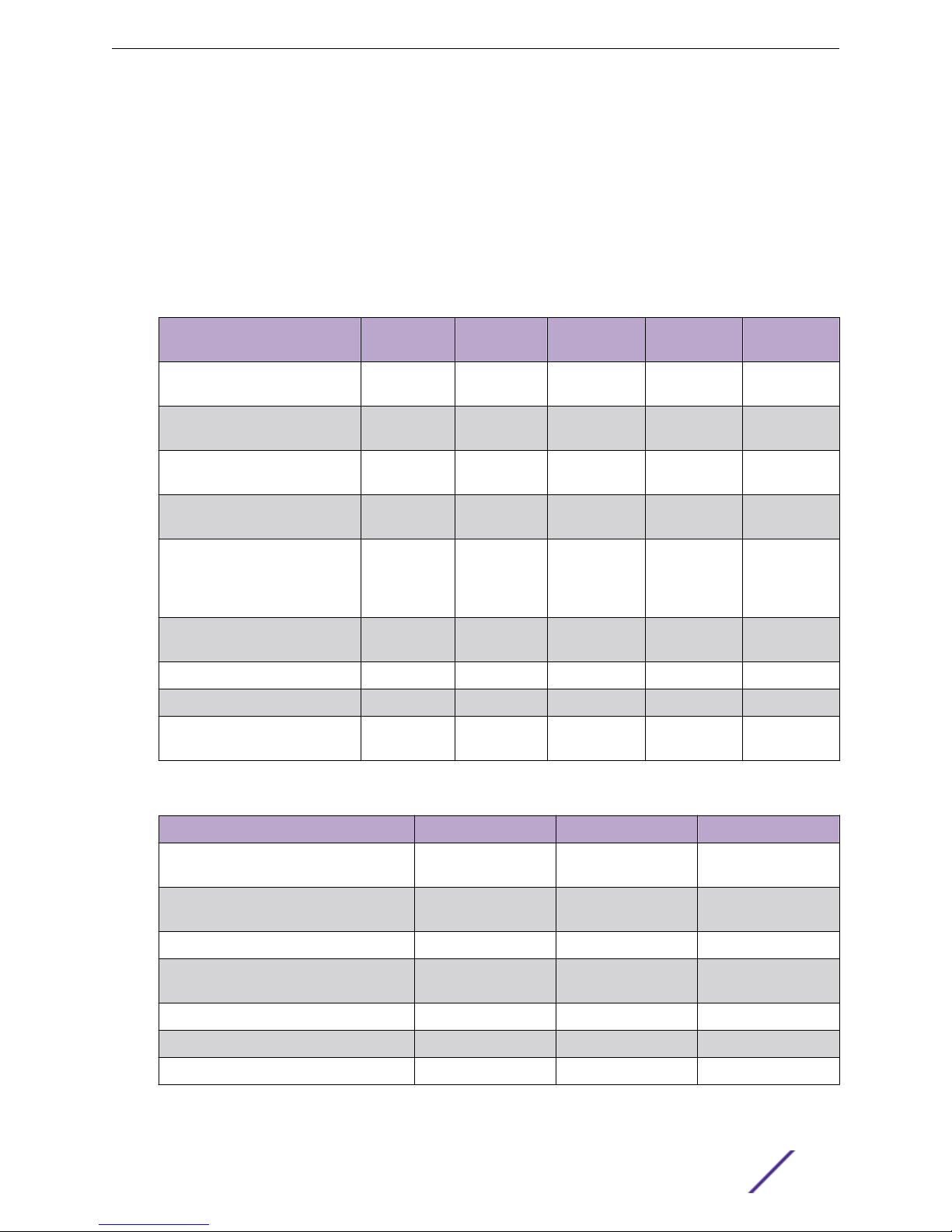
Table 4: Summit Switch Features—Summit X150, X250e, X350, X430, and X440
Series
Feature Summit X150
Series
Summit
X250e Series
Summit X350
Series
Summit X430
Series
Summit X440
Series
Maximum autonegotiating
10/100BASE-TX ports
Maximum autonegotiating
10/100/1000-BASE-TX ports
Maximum 1-Gbps Ethernet ports
(SFP)
Maximum 10-Gbps Ethernet
ports (SFP+)
SummitStack support No Yes No No Yes (except
Total switching capacity 8.8 to 17.6
Redundant power Yes (external) Yes (external) Yes (external) No Yes (external)
DC power available No Yes Yes No Yes
Power over Ethernet (802.3af) Yes Yes No Yes
26 or 50 26 or 50 — — —
2 24 or 48 24 or 48 8 or 24 or 48 8, 24, or 48
2 2 4 4 24
— 2 2 — 2
X440-L2-24t
and X440L2-48t)
Gbps
48.8 to 97.6
Gbps
128 to 256
Gbps
Up to 108
Gbps
(Also 802.3at)
Up to 136
Gbps
Yes
(Also 802.3at)
Table 5: Summit Switch Features—Summit X450, X450a, and X450e Series
Feature Summit X450 Series Summit X450a Series Summit X450e Series
Maximum autonegotiating 10/100BASETX ports
Maximum autonegotiating 10/100/1000BASE-TX ports
Maximum 1-Gbps Ethernet ports (SFP) 4 4 4
Maximum 10-Gbps Ethernet ports (XFP,
XENPAK, SFP+)
SummitStack support Yes Yes Yes
Total switching capacity 128 to 256 Gbps 128 to 256 Gbps 128 to 256 Gbps
Redundant power Yes (external) Yes (external) Yes (external)
Summit Family Hardware Installation Guide 12
— — —
24 or 48 24 or 48 24 or 48
2 2 2
Summit Family Switches
Table 5: Summit Switch Features—Summit X450, X450a, and X450e Series
(continued)
Feature Summit X450 Series Summit X450a Series Summit X450e Series
DC power available No Yes No
Power over Ethernet (802.3af) Yes Yes Yes
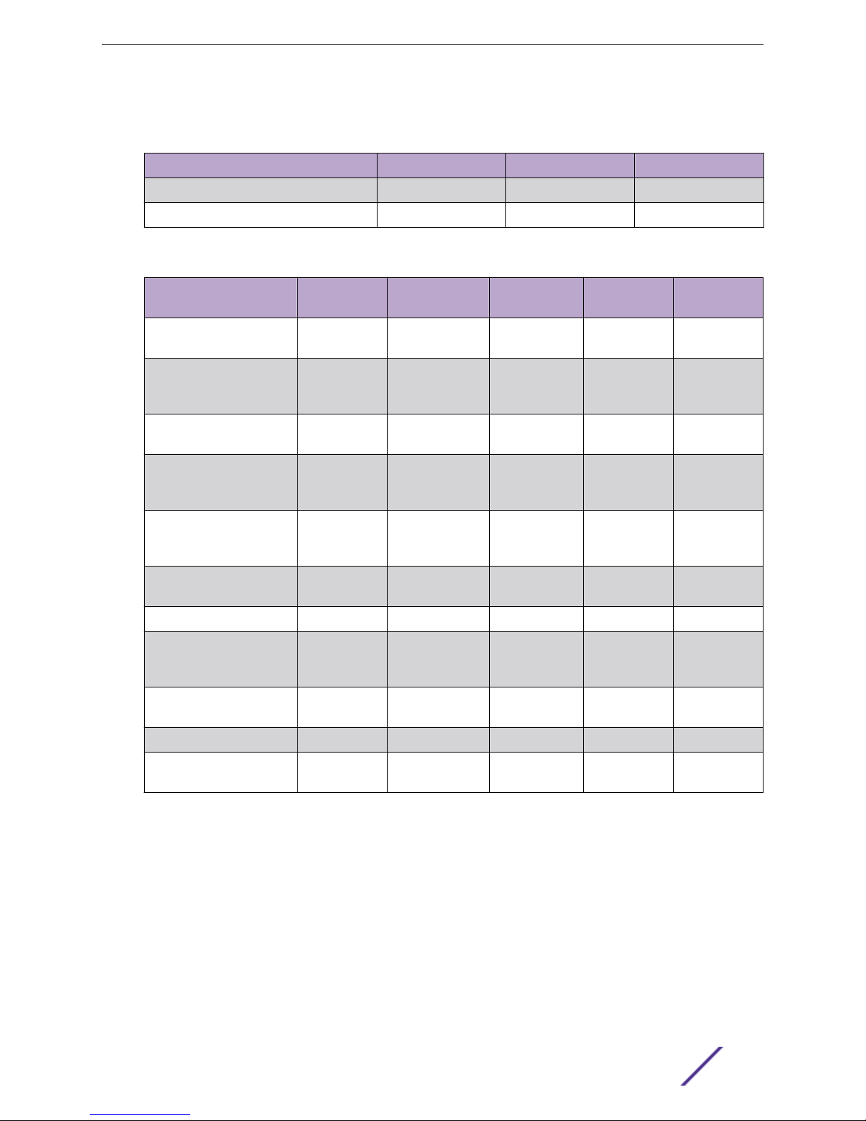
Table 6: Summit Switch Features—Summit X460, X480, X650, X670, and X770 Series
Feature Summit X460
Series
Summit X480
Series
Summit X650
Series
Summit X670
Series
Summit X770
Series
Maximum autonegotiating
10/100BASE-TX ports
Maximum autonegotiating
10/100/1000-BASE-TX
ports
Maximum 1-Gbps Ethernet
ports (SFP)
Maximum 10-Gbps
Ethernet ports (XFP,
XENPAK, SFP+)
Maximum 10G BASE-T
RJ-45 (100 Mbps/1G/10G
tri-speed) ports
Maximum 40GBASE-X
QSFP+ ports
SummitStack support Yes Yes Yes Yes Yes
Total switching capacity 176 to 224
Redundant power Yes (hot-
DC power available Yes Yes Yes Yes Yes
— — — — —
48 48 — — —
24 or 48 24 or 48 4 — —
2 (with
XGM3-2sf)
— — — 48 —
— — — — 32
Gbps
swappable)
4 (with
VIM2-10G4X)
224 to 448 Gbps
(with
VIM2-10G4X)
Yes (hotswappable)
24 (default)
32 (with
VIM1-10G8X)
488 to 680
Gbps
Yes (hotswappable)
48 —
640 Gbps 1280 Gbps
Yes (hotswappable)
Yes (hotswappable)
Power over Ethernet
(802.3af)
Model numbers for the Summit switches are in the following format:
<Series>-<number of front-panel I/O ports><port type><internal power supply type>
The number of ports can be 8, 24, 32, or 48.
•
The port type can be t (copper), p (copper providing Power of Ethernet), q (QSFP+), or x (fiber).
•
For models with integral power supplies, the power supply type can be AC (no designation) or DC.
•
Models with pluggable power supplies can accommodate either AC or DC supplies and have no
power designation in their model numbers.
Summit Family Hardware Installation Guide 13
Yes
(Also 802.3at)
No No No No

Summit Family Switches
For example, the Summit X350-24t switch is in the X350 series, provides 24 copper I/O ports, and has
an AC power supply. The Summit X450a-24xDC switch is in the X450a series, provides 24 fiber I/O
ports, and has a DC power supply.
The following table lists the available switch models in each series.
Table 7: Switch Models in Each Summit Series
Series Available Models
Summit
X150
Summit
X250e
Summit
X350
Summit
X430
Summit
X440
Summit
X450
Summit
X150-24t
Summit
X250e-24t
Summit
X250e-24tDC
Summit
X350-24t
X430-8p X430-24t
X430-24p
Summit
X440-8t
Summit
X440-8p
Summit
X440-24t
X440-24tDC
Summit
X440-24x
Summit
X440-L2-24t
Summit
X440-24t-10G
Summit
X440-24x-10G
Summit
X450-24t*
Summit X150-24p Summit
X150-48t
Summit
X250e-24p
Summit X440-24p
Summit
X440-24p-10G
Summit X250e-24x
Summit
X250e-24xDC
Summit X450-24x*
Summit
X250e-48t
Summit
X350-48t
X430-48t
Summit
X440-48t
X440-48tDC
Summit
X440-L2-48t
Summit
X440-48t-10G
Summit
X250e-48p
Summit
X440-48p
Summit
X440-48p-1
0G
Summit
X450a
Summit
X450e
Summit
X460
Summit
X480
Summit
X650
Summit
X670
Summit
X450a-24t
Summit
X450a-24tDC
Summit
X450e-24t
Summit
X460-24t
Summit
X650-24t**
Summit X450a-24x Summit
X450a-48t
Summit
X450a-48tDC
Summit
X450e-24p
Summit X460-24p Summit X460-24x Summit
Summit X480-24x* Summit
Summit
X650-24x**
Summit
X450e-48t
X460-48t
X480-48t*
Summit
X450e-48p
Summit
X460-48p
Summit
X460-48x
Summit
X480-48x*
Summit
X670-48x
Summit
X670V-48x
Summit
X670V-48t
Summit Family Hardware Installation Guide 14

Table 7: Switch Models in Each Summit Series (continued)
Series Available Models
Summit Family Switches
Summit
X770
*These Summit switch models are not available in TAA versions.**These Summit switch models do not have separate TAA and non-TAA versions; all Summit
X650 series models are TAA-compliant.
Summit X770-32q
Note
See the ExtremeXOS Concepts Guide and the ExtremeXOS Command Reference Guide for
feature-specific information about the Summit switches and for information regarding switch
configuration.
Combination Ports and Failover
Summit family switches provide two, four, or twelve uplink ports implemented as combination ports
that pair a copper port using RJ-45 connectors with an optical port using LC connectors.
The copper port operates as an autonegotiating 10/100/1000BASE-T port. The optical port allows
Gigabit Ethernet uplink connections through Extreme Networks small form factor pluggable (SFP)
interface modules. See the individual switch descriptions for the port numbers of the combination ports
on each switch model.
Summit family switches support automatic failover from an active fiber port to a copper backup or
from an active copper port to a fiber port. If one of the uplink connections fails, the Summit uplink
connection automatically fails over to the second connection. To set up a redundant link on a
combination port, connect the active 1000BASE-T and fiber links to both the RJ-45 and SFP interfaces
of that port.
Gigabit Ethernet uplink redundancy on the Summit family switches follows these rules:
With both the SFP and 1000BASE-T interfaces connected on a combination port, only one interface
•
can be activated. The other is inactive.
If only one interface is connected, the switch activates the connected interface.
•
The switch determines whether the port uses the fiber or copper connection based on the order in
•
which the connectors are inserted into the switch. When the switch senses that an SFP and a
copper connector are inserted, the switch enables the uplink redundancy feature. For example, if
you first connect copper ports 25 and 26 on a Summit X250e-24t switch, and then insert SFPs into
ports 25 and 26, the switch assigns the copper ports as active ports and the fiber ports as
redundant ports.
Hardware identifies when a link is lost and responds by swapping the primary and redundant ports to
maintain stability. After a failover occurs, the switch keeps the current port assignment until another
failure occurs or a user changes the assignment using the CLI. For more information about configuring
automatic failover on combination ports, see the ExtremeXOS Concepts Guide.
Summit Family Hardware Installation Guide 15

Summit Family Switches
Summit X150 Series Switches
The Summit X150 series switches provide 24 or 48 fixed 10/100BASE-T Ethernet ports that deliver
high-density copper connectivity at 2.4 Gbps or 4.8 Gbps.
Models are available with PoE and without PoE. Each Summit X150 series switch has two combination
ports that provide 10/100/1000 BASE-T or SFP connectivity for 2 Gbps of copper or fiber connectivity.
A serial console port on the front panel allows you to connect a terminal and perform local
management. On the back of the switch, an Ethernet management port can be used to connect the
system to a parallel management network for administration. Alternatively, you can use an Ethernet
cable to connect this port directly to a laptop to view and locally manage the switch configurations.
The rear panel of the switch provides an AC power input socket and a redundant power connector. The
internal power supply operates from 100 VAC to 240 VAC. The switch automatically adjusts to the
supply voltage. The redundant power connector allows you to connect the switch to the EPS-160 or
EPS-500 external power supply. When a compatible external power supply is used with the Summit
X150 series switch, the internal and external power supplies are fully fault tolerant and load-sharing. If
one power supply fails, the other power supply will provide sufficient power to operate the switch.
The Summit X150e series switches include the following switch models:
Summit X150-24t Switch
•
Summit X150-24t-TAA switch
•
Summit X150-24p Switch
•
Summit X150-24p-TAA switch
•
Summit X150-48t switch
•
Summit X150-48t-TAA switch
•
Note
In the descriptions that follow, references to a Summit X150 series model number also apply
to the equivalent TAA-compliant switch version.
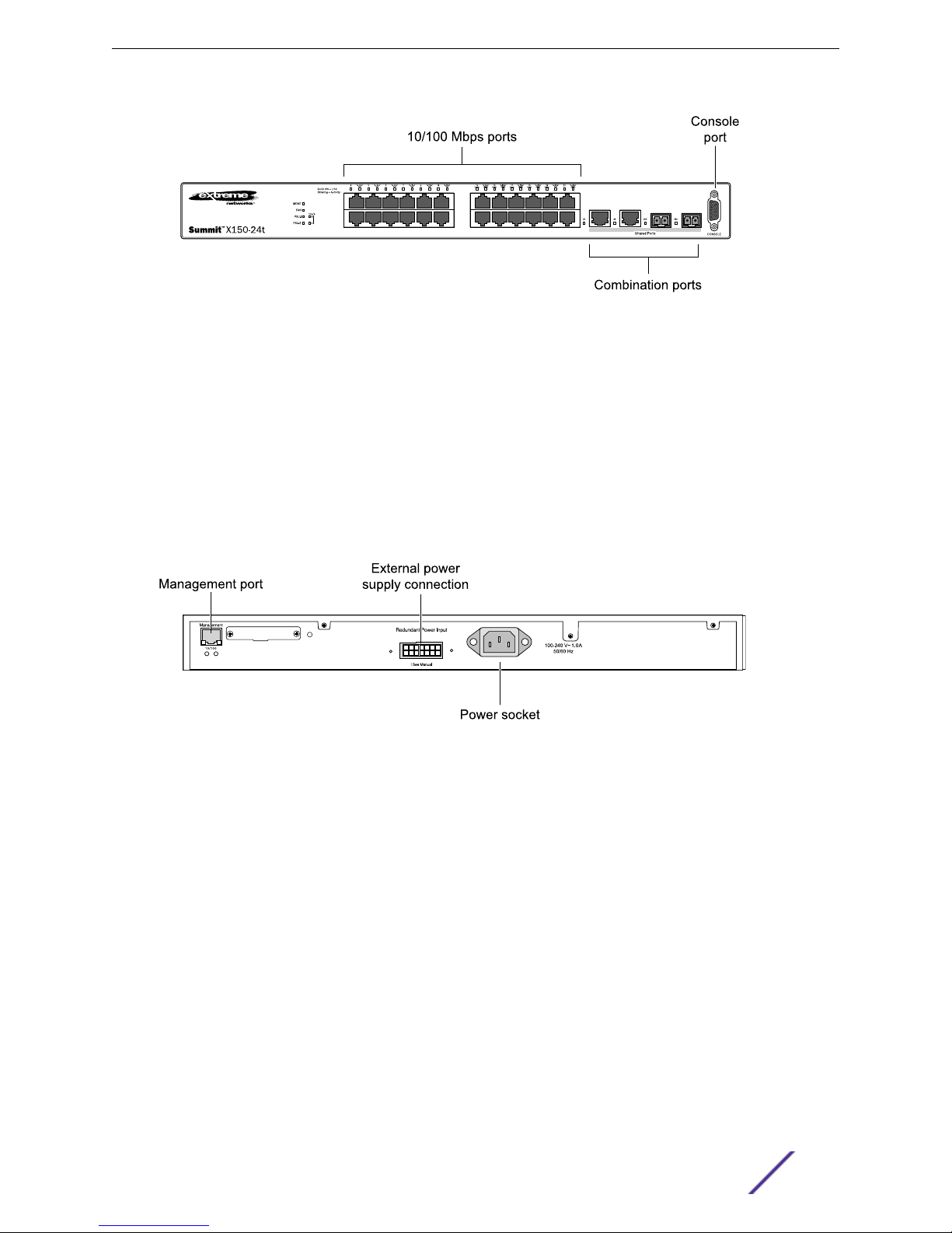
Summit X150-24t Switch
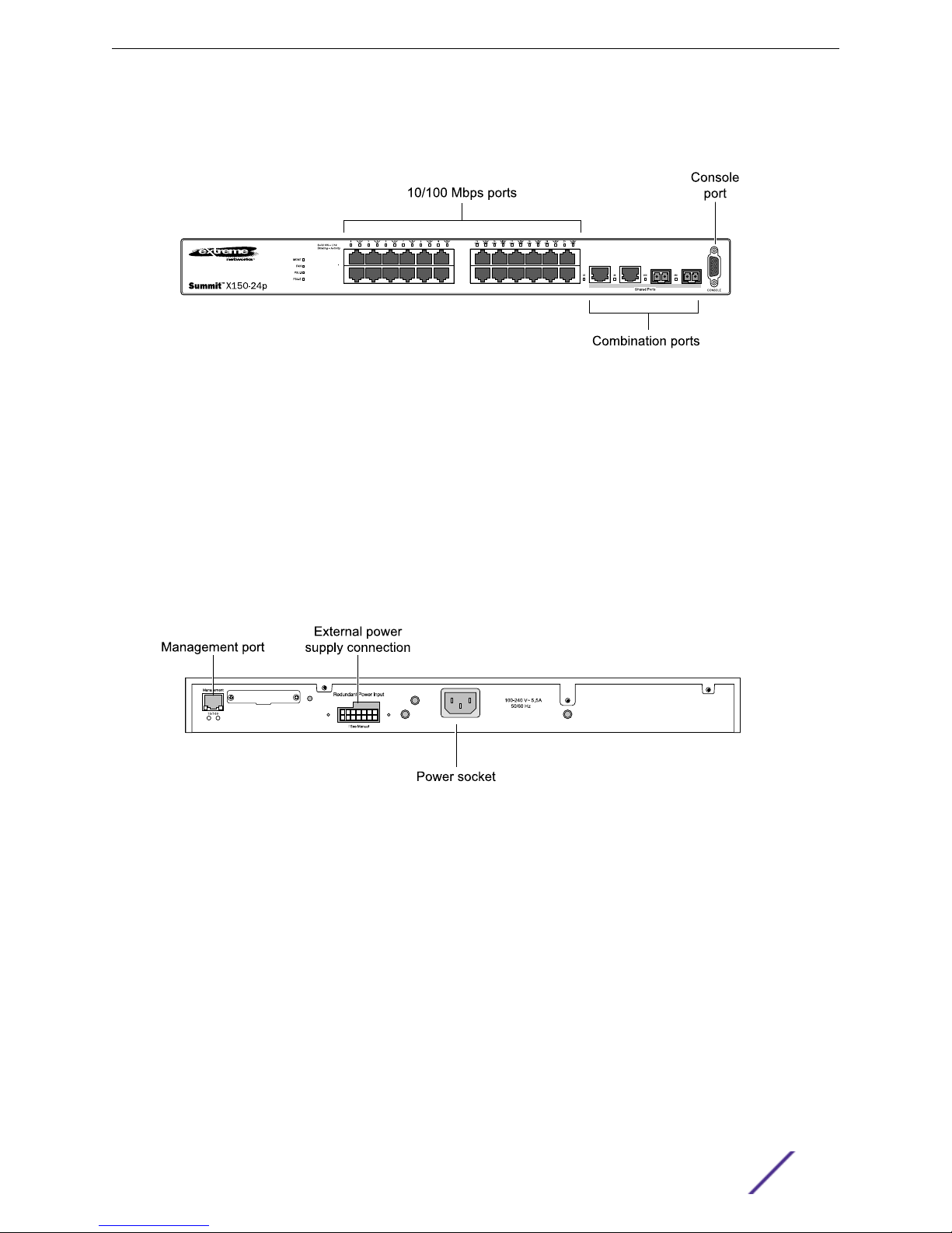
The front panel of the Summit X150-24t switch includes:
Twenty-four fixed autosensing 10/100BASE-T ports (ports 1–24) that provide 2.4 Gbps of high-
•
density copper connectivity
Two combination ports (ports 25–26) using RJ-45 connectors and SFPs to provide 2 Gbps of
•
copper or fiber connectivity
For more information about combination ports, see Combination Ports and Failover.
For information about SFPs, see the Extreme Networks Pluggable Interface Modules Installation
Guide.
LEDs to indicate port status and switch operating conditions
•
For a description of the LEDs and their operation, see Summit X150 Series Switch LEDs.
Serial console port used to connect a terminal and perform local management
•
Summit Family Hardware Installation Guide 16
Summit Family Switches
Figure 1: Summit X150-24t Switch Front Panel
The rear panel of the Summit X150-24t switch (shown in Figure 2: Summit X150-24t Switch Rear Panel
on page 17) includes:
Ethernet management port with associated LEDs
•
Redundant power input connector for optional connection to the EPS-160 External Power Module
•
See EPS-160 External Power Module (with EPS-T) for more information. The connecting redundant
power supply cable is shipped with the EPS-160 unit.
AC power input socket
•
The internal AC power supply operates from 100 VAC to 240 VAC.
Figure 2: Summit X150-24t Switch Rear Panel
Summit X150-24p Switch
The front panel of the Summit X150-24p switch includes:
Twenty-four fixed autosensing 10/100BASE-T PoE ports (ports 1–24). In addition to 4 Gbps of high-
•
density copper connectivity, these ports also provide a full 15.4 Watts of PoE per port.
Two combination ports (ports 25–26) using RJ-45 connectors and SFPs to provide 2 Gbps of
•
copper or fiber connectivity.
For more information about combination ports, see Combination Ports and Failover.
For information about SFPs, see the Extreme Networks Pluggable Interface Modules Installation
Guide.
LEDs to indicate port status and switch operating conditions.
•
Summit Family Hardware Installation Guide 17
Summit Family Switches
For a description of the LEDs and their operation, see Summit X150 Series Switch LEDs.
Serial console port used to connect a terminal and perform local management.
•
Figure 3: Summit X150-24p Switch Front Panel
The rear panel of the Summit X150-24p switch includes:
Ethernet management port with associated LEDs
•
Redundant power input connector for optional connection to the EPS-500 External Power Supply
•
(Model No. 10911) with full PoE power support
The connecting redundant power supply cable is shipped with the EPS-500 unit. See EPS-500
External Power Supply Unit for more information.
AC power input socket
•
The internal AC power supply operates from 100 VAC to 240 VAC.
Figure 4: Summit X150-24p Switch Rear Panel
Summit X150-48t Switch
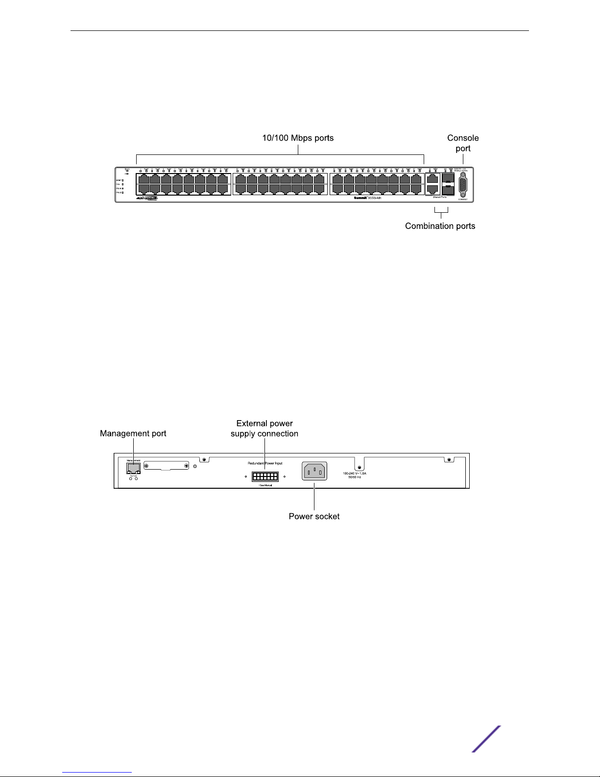
The front panel of the Summit X150-48t switch includes:
Forty-eight fixed autosensing 10/100BASE-T ports (ports 1–48) that provide 4.8 Gbps of high-
•
density copper connectivity
Two combination ports (ports 49–50) using RJ-45 connectors and SFPs to provide 2 Gbps of
•
copper or fiber connectivity
For more information about combination ports, see Combination Ports and Failover.
For information about SFPs, see the Extreme Networks Pluggable Interface Modules Installation
Guide.
Summit Family Hardware Installation Guide 18
Summit Family Switches
LEDs to indicate port status and switch operating conditions
•
For a description of the LEDs and their operation, see Summit X150 Series Switch LEDs.
Serial console port used to connect a terminal and perform local management
•
Figure 5: Summit X150-48t Switch Front Panel
The rear panel of the Summit X150-48t switch (Figure 6: Summit X150-48t Switch Rear Panel on page
19) includes:
Management port with associated LEDs
•
Redundant power input connector for optional connection to the EPS-160 External Power Module
•
The connecting redundant power supply cable is shipped with the EPS-160 unit. See EPS-160
External Power Module (with EPS-T) for more information.
AC power input socket
•
The internal AC power supply operates from 100 VAC to 240 VAC.
Figure 6: Summit X150-48t Switch Rear Panel
Summit X150 Series Switch LEDs
The following describes the meanings of the LEDs on the Summit X150 switches.
Summit Family Hardware Installation Guide 19
LEDs on the Summit X150 Series Switches
Table 8: Front Panel
Label or Type Color/State Meaning
MGMT Blinking green (fast) Power-on self-test (POST) in progress.
Steady green POST passed. System is booting image.
Blinking green (slow) Normal operation.
Blinking amber Switch diagnostics are running.
or
System is disabled. POST failed or system overheated.
Off No external power attached.
FAN Steady green Normal operation.
Blinking amber Fan failure. Switch will continue to operate unless it overheats.
Off No power.
Summit Family Switches
PSU-I
(Internal power
supply)
PSU-E
(External power
supply)
Port number
1 – 24 or 1 – 48
Port number
25, 26 or 49, 50
(Shared ports)
Steady green Normal operation.
Blinking amber Failure.
Off No power.
Steady green Normal operation.
Blinking amber Failure.
Off No external power attached.
Steady green Link is OK.
Blinking green Port is transmitting packets.
Off Link is not present, or port is disabled.
Steady green Link is OK.
Blinking green Activity.
Off Link is not present, or port is disabled.
Table 9: Additional Port LED Meanings for PoE Switch: Summit X150-24p
Label or Type Color/State Meaning
All front-panel ports Steady green Link OK; port is not powered.
Steady amber Link is OK; port is powered; no traffic.
Blinking green Link is OK and transmitting packets; port is not powered.
Blinking amber Link is OK and transmitting packets; port is powered.
Slow blinking amber No link, or disabled port; port is powered.
Alternating amber and
green
Off Port is not powered, has no link, or is disabled.
Summit Family Hardware Installation Guide 20
Port has a power fault.

Table 10: Rear Panel
Label or Type Color/State Meaning
Summit Family Switches
Management Port Right LED:
Steady green
Left LED:
Blinking green
Both LEDs off Link is not present.
Link is OK.
Activity.
Summit X250e Series Switches
The Summit X250e series switches provide 24 or 48 Ethernet ports that deliver high-density fast
Ethernet connectivity using fixed 10/100/1000BASE-T ports or installable small form pluggable (SFP)
optical modules.
Fixed-port models are available either with or without PoE. Each Summit X250e series switch has two
combination ports that provide 10/100/1000 BASE-T or SFP connectivity for 2 Gbps of copper or fiber
connectivity. A serial console port on the front panel allows you to connect a terminal and perform local
management. An Ethernet management port can be used to connect the system to a parallel
management network for administration. Alternatively, you can use an Ethernet cable to connect this
port directly to a laptop to view and locally manage the switch configurations.
On the back of the switch, two high-speed stacking ports allow you to combine multiple units into a
single SummitStack management entity. The rear panel also provides an AC or DC power input socket
and a redundant power connector. (See specific switch descriptions for more information about the
power options.) The switch automatically adjusts to the supply voltage. The redundant power
connector allows you to connect the switch to the EPS-160, EPS-500, or EPS-150DC external power
supply. When a compatible external power supply is used with the Summit X250e series switch, the
internal and external power supplies are fully fault tolerant and load-sharing. If one power supply fails,
the other power supply will provide sufficient power to operate the switch.
The Summit X250e series switches include the following models:
Summit X250e-24t Switch
•
Summit X250e-24t-TAA switch
•
Summit X250e-24tDC Switch
•
Summit X250e-24tDC-TAA switch
•
Summit X250e-24p Switch
•
Summit X250e-24p-TAA switch
•
Summit X250e-24x Switch
•
Summit X250e-24x-TAA switch
•
Summit X250e-24xDC Switch
•
Summit X250e-24x-TAA switch
•
Summit X250e-48t Switch
•
Summit X250e-48t-TAA switch
•
Summit X250e-48tDC Switch
•
Summit X250e-48tDC-TAA switch
•
Summit Family Hardware Installation Guide 21
Summit X250e-48p Switch
•
Summit X250e-48p-TAA switch
•
Note
In the descriptions that follow, references to a Summit X250e series model number also apply
to the equivalent TAA-compliant switch version.
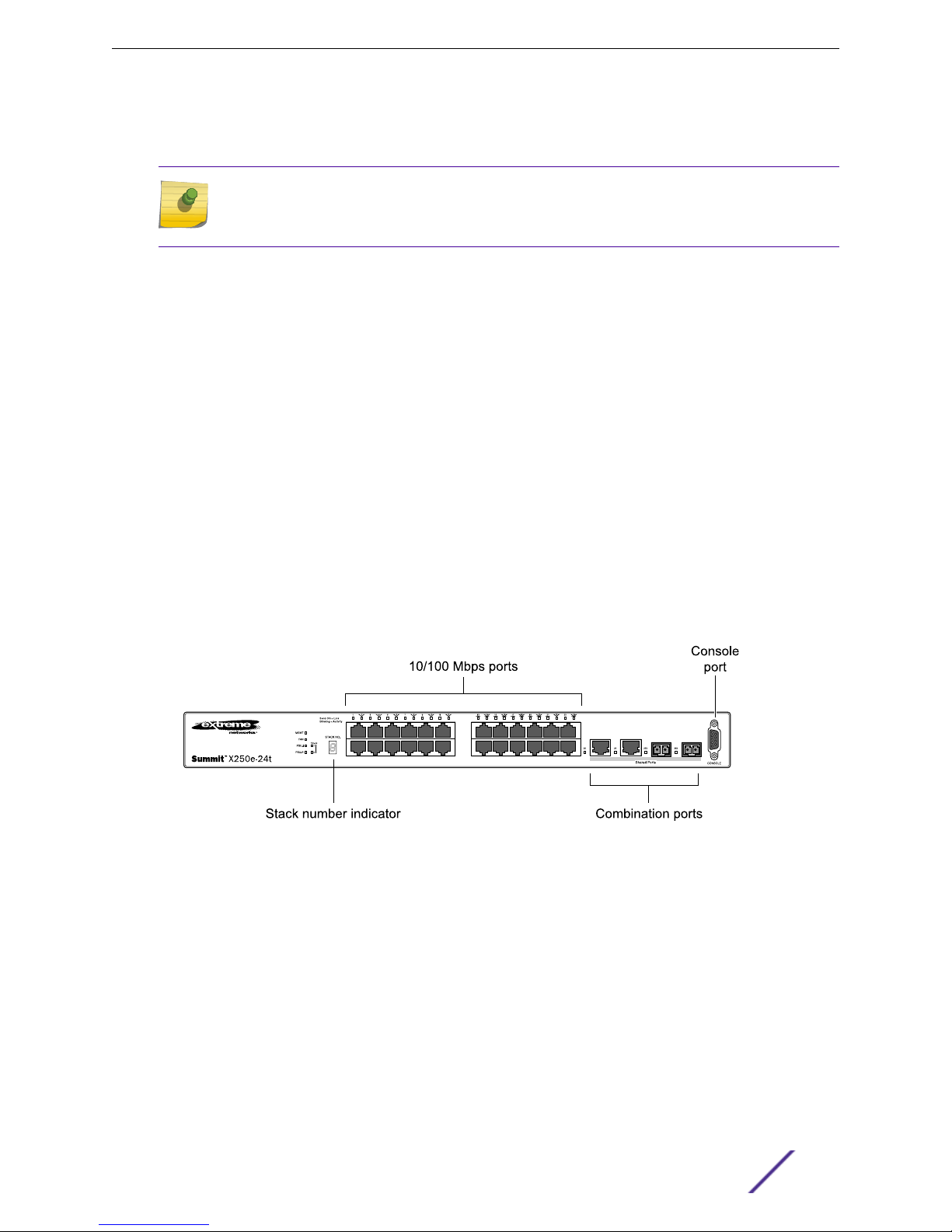
Summit X250e-24t Switch
The front panel of the Summit X250e-24t switch includes:
Twenty-four fixed autosensing 10/100BASE-T ports (ports 1–24) that provide 2.4 Gbps of high-
•
density copper connectivity
Two combination ports (ports 25–26) using RJ-45 connectors and SFPs to provide 2 Gbps of
•
copper or fiber connectivity
For more information about combination ports, see Combination Ports and Failover.
Summit Family Switches
For information about SFPs, see the Extreme Networks Pluggable Interface Modules Installation
Guide.
LEDs to indicate port status and switch operating conditions
•
For a description of the LEDs and their operation, see Summit X250e Series Switch LEDs.
Stack number indicator showing the position of this switch in a stacked configuration
•
Serial console port used to connect a terminal and perform local management.
•
Figure 7: Summit X250e-24t Switch Front Panel
The rear panel of the Summit X250e-24t switch (shown in Figure 8: Summit X250e-24t Switch Rear
Panel on page 23) includes:
Ethernet management port with associated LEDs
•
Two high-performance stacking ports with associated LEDs
•
Redundant power input connector for optional connection to the EPS-160 External Power Module
•
The connecting redundant power supply cable is shipped with the EPS-160 unit. See EPS-160
External Power Module (with EPS-T) for more information.
AC power input socket
•
The internal AC power supply operates from 100 VAC to 240 VAC.
Summit Family Hardware Installation Guide 22
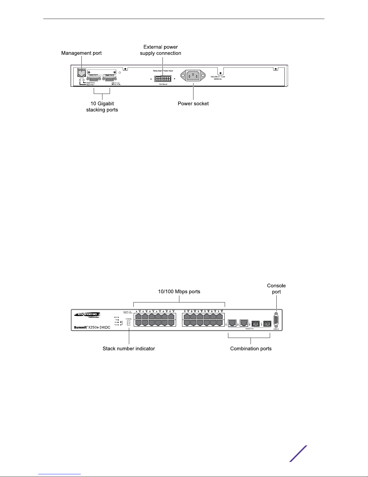
Figure 8: Summit X250e-24t Switch Rear Panel
Summit X250e-24tDC Switch
The front panel of the Summit X250e-24tDC switch includes:
Twenty-four fixed autosensing 10/100BASE-T ports (ports 1–24) that provide 2.4 Gbps of high-
•
density copper connectivity
Two combination ports (ports 25–26) using RJ-45 connectors and SFPs to provide 2 Gbps of
•
copper or fiber connectivity
Summit Family Switches
For more information about combination ports, see Combination Ports and Failover.
For information about SFPs, see the Extreme Networks Pluggable Interface Modules Installation
Guide.
LEDs to indicate port status and switch operating conditions
•
For a description of the LEDs and their operation, see Summit X250e Series Switch LEDs.
Stack number indicator showing the position of this switch in a stacked configuration
•
Serial console port used to connect a terminal and perform local management
•
Figure 9: Summit X250e-24tDC Switch Front Panel
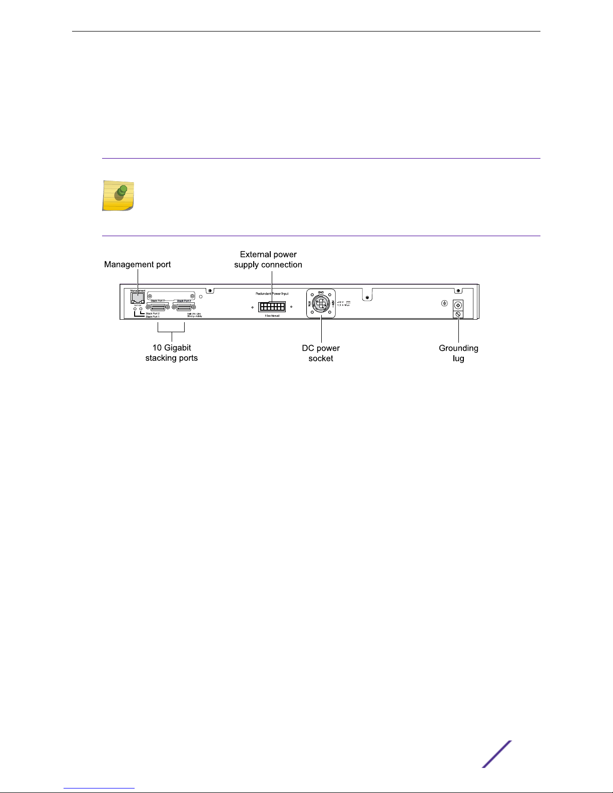
The rear panel of the Summit X250e-24tDC switch (shown in Figure 10: Summit X250e-24tDC Switch
Rear Panel on page 24) includes:
Ethernet management port with associated LEDs
•
Two high-performance stacking ports with associated LEDs
•
Redundant power input connector for optional connection to the EPS-150DC External Power
•
Module (Model No. 10909).
Summit Family Hardware Installation Guide 23
Summit Family Switches
The connecting redundant power supply cable is shipped with the EPS-150DC unit. See EPS-150DC
External Power Module (with EPS-T2) for more information.
DC power input socket
•
The internal power supply operates from -36 VDC to -72 VDC.
Grounding lug
•
Note
For centralized DC power connection, this product is intended to be installed in a restricted
access location (such as a dedicated equipment room, equipment closet, or central office) in
accordance with Articles 110-16, 110-17, and 110-18 of the National Electric Code, ANSI/NFPA
70.
Figure 10: Summit X250e-24tDC Switch Rear Panel
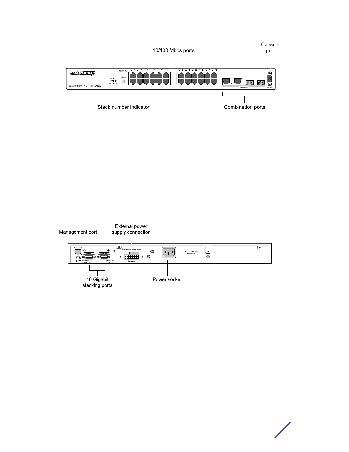
Summit X250e-24p Switch
The front panel of the Summit X250e-24p switch includes:
Twenty-four fixed autosensing 10/100BASE-T PoE ports (ports 1–24). In addition to 2.4 Gbps of
•
high-density copper connectivity, these ports also provide a full 15.4 Watts of PoE per port.
Two combination ports (ports 25–26) using RJ-45 connectors and SFPs to provide 2 Gbps of
•
copper or fiber connectivity
For more information about combination ports, see Combination Ports and Failover.
For information about SFPs, see the Extreme Networks Pluggable Interface Modules Installation
Guide.
LEDs to indicate port status and switch operating conditions
•
For a description of the LEDs and their operation, see Summit X250e Series Switch LEDs.
Stack number indicator showing the position of this switch in a stacked configuration
•
Serial console port used to connect a terminal and perform local management
•
Summit Family Hardware Installation Guide 24
Summit Family Switches
Figure 11: Summit X250e-24p Switch Front Panel
The rear panel of the Summit X250e-24p switch (shown in Figure 12: Summit X250e-24p Switch Rear
Panel on page 25) includes:
Ethernet management port with associated LEDs
•
Two high-performance stacking ports with associated LEDs
•
Redundant power input connector for use with the EPS-500 External Power Supply (Model No.
•
10911) with full PoE power support
The connecting redundant power supply cable is shipped with the EPS-500 unit. See EPS-500
External Power Supply Unit for more information.
AC power input socket
•
The internal AC power supply operates from 100 VAC to 240 VAC.
Figure 12: Summit X250e-24p Switch Rear Panel
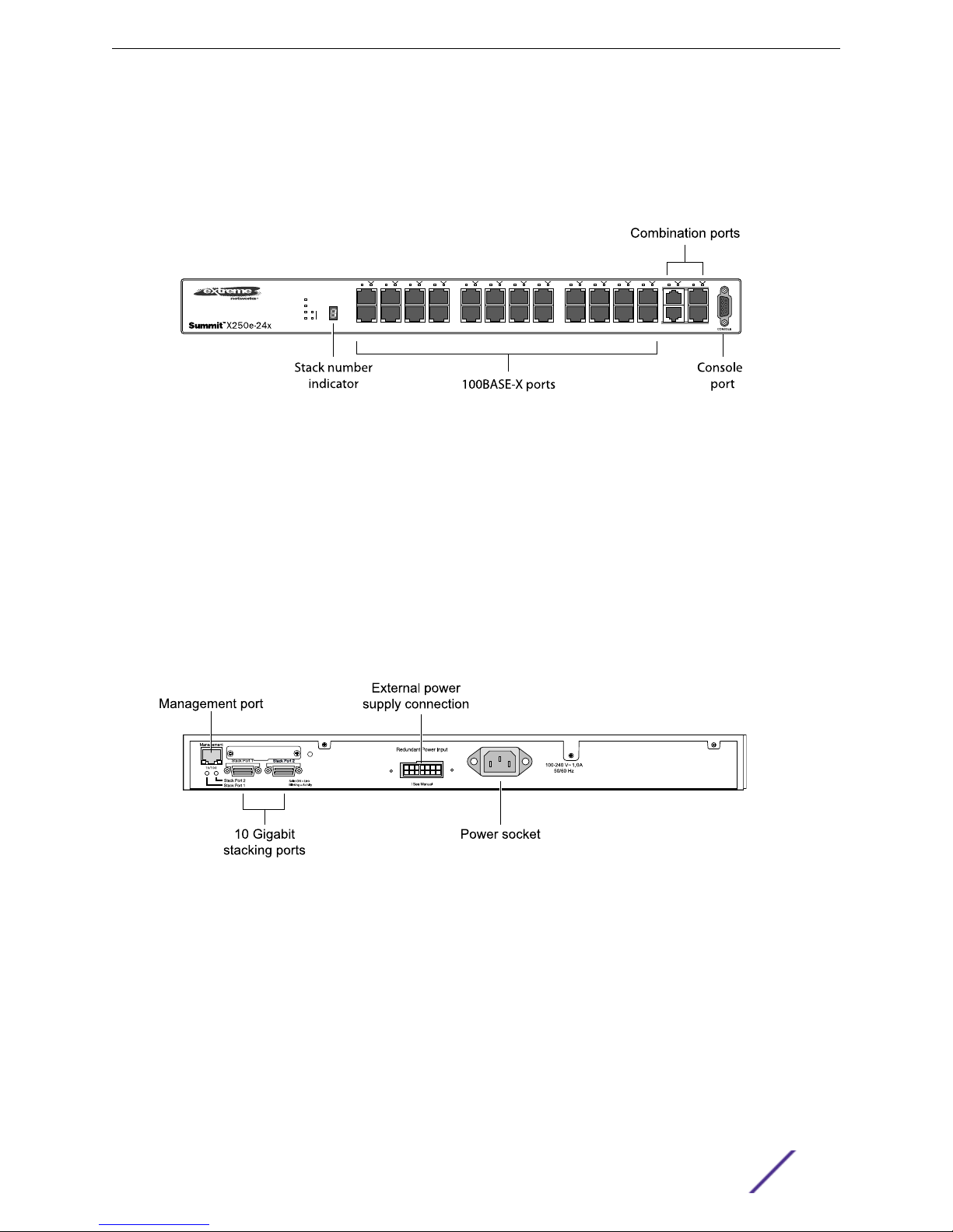
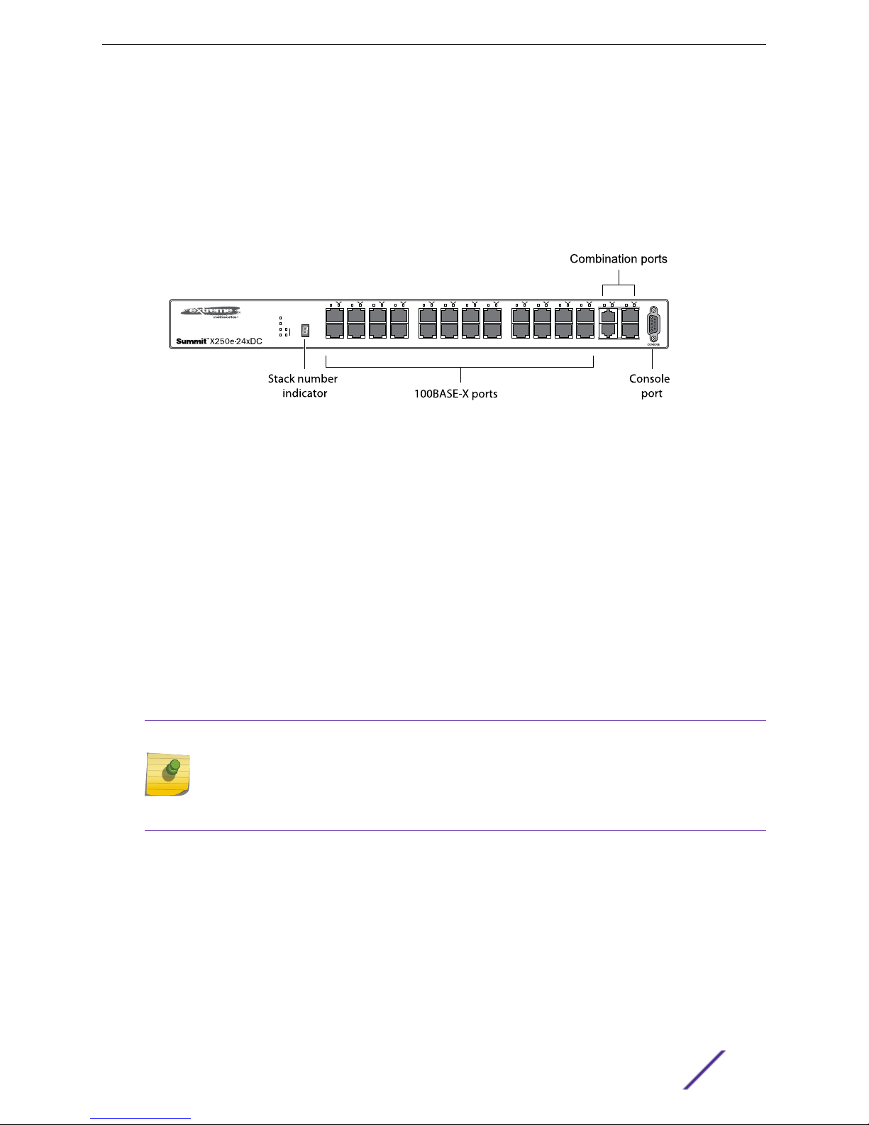
Summit X250e-24x Switch
The front panel of the Summit X250e-24x switch includes:
Twenty-four 100BASE-FX ports (ports 1–24) that provide 2.4 Gbps of high-density fiber
•
connectivity
Two combination ports (ports 25–26) using RJ-45 connectors and SFPs to provide 2 Gbps of
•
copper or fiber connectivity
For more information about combination ports, see Combination Ports and Failover.
For information about SFPs, see the Extreme Networks Pluggable Interface Modules Installation
Guide.
Summit Family Hardware Installation Guide 25
Summit Family Switches
LEDs to indicate port status and switch operating conditions
•
For a description of the LEDs and their operation, see Summit X250e Series Switch LEDs.
Stack number indicator showing the position of this switch in a stacked configuration
•
Serial console port used to connect a terminal and perform local management
•
Figure 13: Summit X250e-24x Switch Front Panel
The rear panel of the Summit X250e-24x switch (shown in Figure 14: Summit X250e-24x Switch Rear
Panel on page 26) includes:
Ethernet management port with associated LEDs
•
Two high-performance stacking ports with associated LEDs
•
Redundant power input connector for use with the EPS-160 External Power Module
•
The connecting redundant power supply cable is shipped with the EPS-160 unit. See EPS-160
External Power Module (with EPS-T) for more information.
AC power input socket
•
The internal AC power supply operates from 100 VAC to 240 VAC.
Figure 14: Summit X250e-24x Switch Rear Panel
Summit X250e-24xDC Switch
The front panel of the Summit X250e-24xDC switch includes:
Twenty-four 100BASE-FX ports (ports 1–24) that provide 2.4 Gbps of high-density fiber
•
connectivity
Two combination ports (ports 25–26) using RJ-45 connectors and SFPs to provide 2 Gbps of
•
copper or fiber connectivity
For more information about combination ports, see Combination Ports and Failover.
Summit Family Hardware Installation Guide 26
Summit Family Switches
For information about SFPs, see the Extreme Networks Pluggable Interface Modules Installation
Guide.
LEDs to indicate port status and switch operating conditions
•
For a description of the LEDs and their operation, see Summit X250e Series Switch LEDs.
Stack number indicator showing the position of this switch in a stacked configuration
•
Serial console port used to connect a terminal and perform local management
•
Figure 15: Summit X250e-24xDC Switch Front Panel
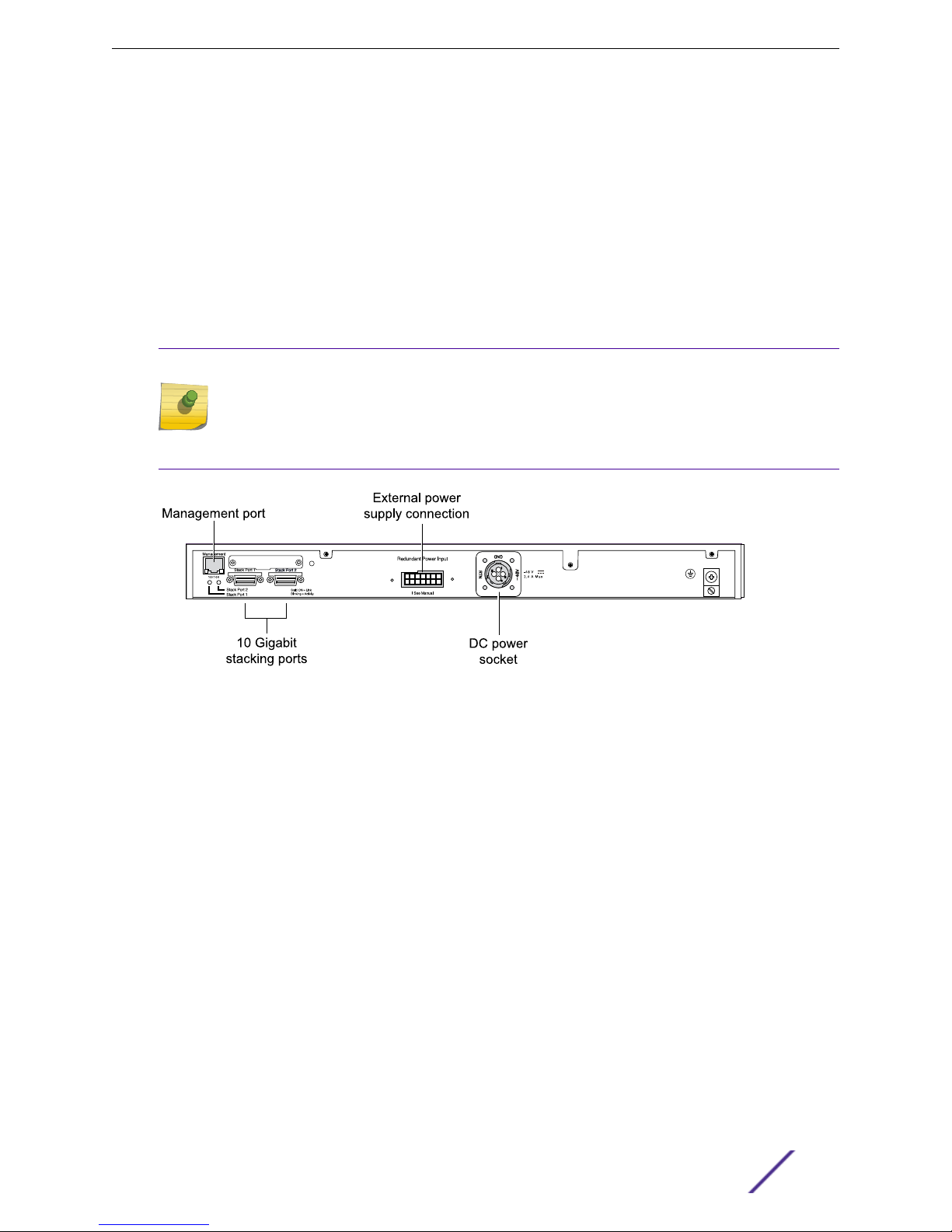
The rear panel of the Summit X250e-24xDC switch (Figure 16: Summit X250e-24xDC Switch Rear Panel
on page 28) includes:
Ethernet management port with associated LEDs
•
Two high-performance stacking ports with associated LEDs
•
Redundant power input connector for use with the EPS-150DC External Power Module (Model No.
•
10909)
The connecting redundant power supply cable is shipped with the EPS-150DC unit. See EPS-150DC
External Power Module (with EPS-T2) for more information.
DC power input socket
•
The internal power supply operates from -36 VDC to -72 VDC.
Grounding lug
•
Note
For centralized DC power connection, this product is intended to be installed in a restricted
access location (such as a dedicated equipment room, equipment closet, or central office) in
accordance with Articles 110-16, 110-17, and 110-18 of the National Electric Code, ANSI/NFPA
70.
Summit Family Hardware Installation Guide 27
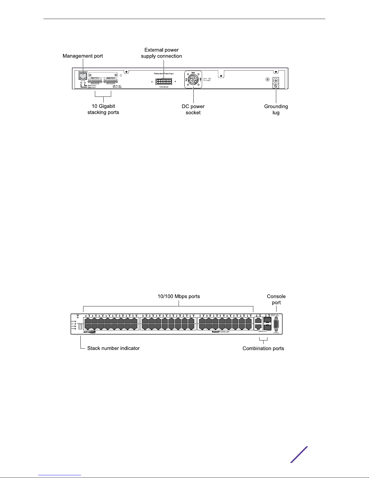
Figure 16: Summit X250e-24xDC Switch Rear Panel
Summit X250e-48t Switch
The front panel of the Summit X250e-48t switch includes:
Forty-eight fixed autosensing 10/100BASE-T ports (ports 1–48) that provide 4.8 Gbps of high-
•
density copper connectivity
Two combination ports (ports 49–50) using RJ-45 connectors and SFPs to provide 2 Gbps of
•
copper or fiber connectivity
Summit Family Switches
For more information about combination ports, see Combination Ports and Failover.
For information about SFPs, see the Extreme Networks Pluggable Interface Modules Installation
Guide.
LEDs to indicate port status and switch operating conditions
•
For a description of the LEDs and their operation, see Summit X250e Series Switch LEDs.
Stack number indicator showing the position of this switch in a stacked configuration
•
Serial console port used to connect a terminal and perform local management
•
Figure 17: Summit X250e-48t Switch Front Panel
The rear panel of the Summit X250e-48t switch (Figure 18: Summit X250e-48t Switch Rear Panel on
page 29) includes:
Management port with associated LEDs
•
Two high-performance stacking ports with associated LEDs
•
Redundant power input connector for optional connection to the EPS-160 External Power Module
•
Summit Family Hardware Installation Guide 28
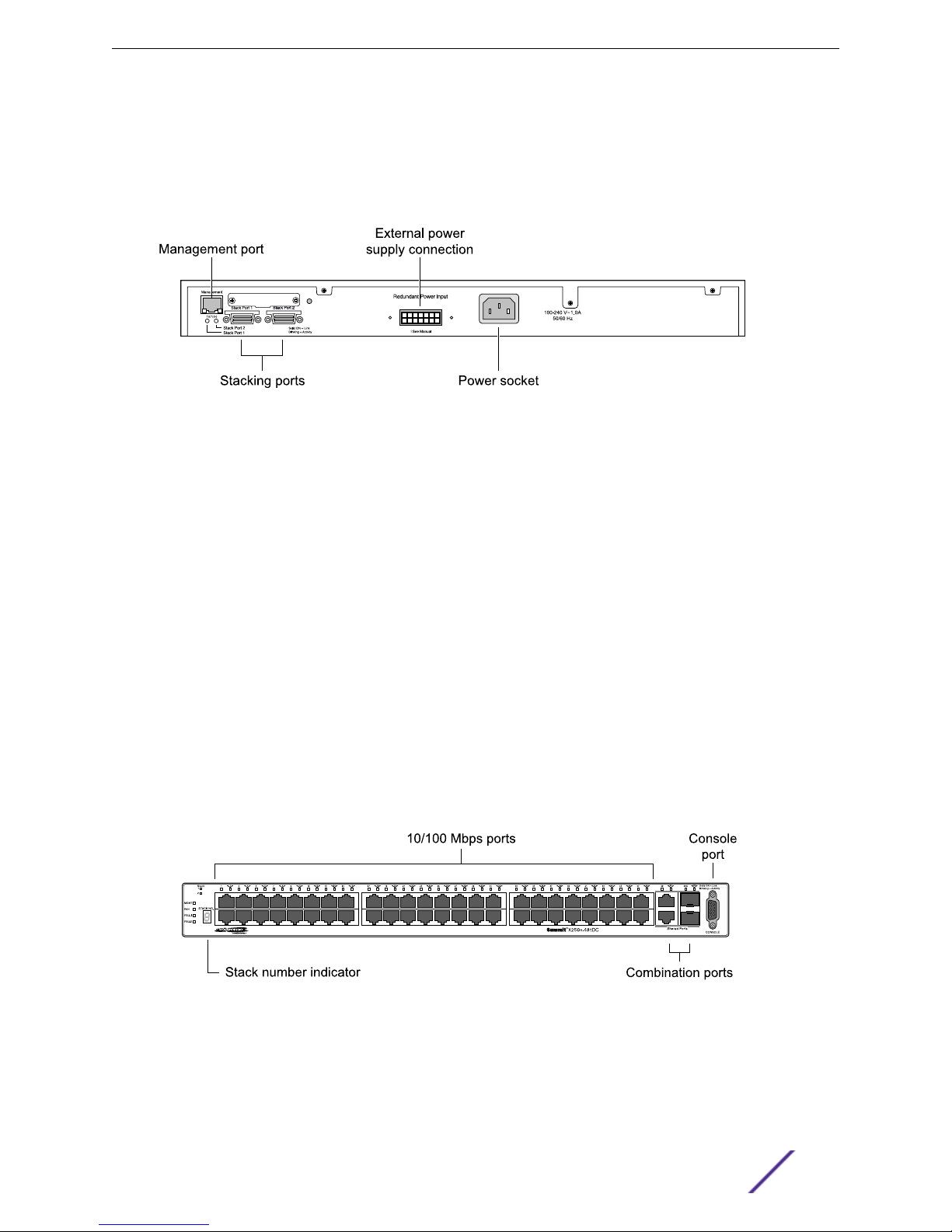
The connecting redundant power supply cable is shipped with the EPS-160 unit. See EPS-160
External Power Module (with EPS-T) for more information.
AC power input socket
•
The internal AC power supply operates from 100 VAC to 240 VAC.
Figure 18: Summit X250e-48t Switch Rear Panel
Summit X250e-48tDC Switch
Summit Family Switches
The front panel of the Summit X250e-48tDC switch includes:
Forty-eight fixed autosensing 10/100BASE-T ports (ports 1–48) that provide 4.8 Gbps of high-
•
density copper connectivity
Two combination ports (ports 49–50) using RJ-45 connectors and SFPs to provide 2 Gbps of
•
copper or fiber connectivity
For more information about combination ports, see Combination Ports and Failover.
For information about SFPs, see the Extreme Networks Pluggable Interface Modules Installation
Guide.
LEDs to indicate port status and switch operating conditions
•
For a description of the LEDs and their operation, see Summit X250e Series Switch LEDs.
Stack number indicator showing the position of this switch in a stacked configuration
•
Serial console port used to connect a terminal and perform local management
•
Figure 19: Summit X250e-48tDC Switch Front Panel
The rear panel of the Summit X250e-48tDC switch (shown in Figure 20: Summit X250e-48tDC Switch
Rear Panel on page 30) includes:
Summit Family Hardware Installation Guide 29
Summit Family Switches
Management port with associated LEDs
•
Two high-performance stacking ports with associated LEDs
•
Redundant power input connector for use with the EPS-150DC External Power Module (Model No.
•
10909).
The connecting redundant power supply cable is shipped with the EPS-150DC unit. See EPS-150DC
External Power Module (with EPS-T2) for more information.
DC power input socket
•
The internal power supply operates from -36 VDC to -72 VDC.
Grounding lug
•
Note
For centralized DC power connection, this product is intended to be installed in a restricted
access location (such as a dedicated equipment room, equipment closet, or central office) in
accordance with Articles 110-16, 110-17, and 110-18 of the National Electric Code, ANSI/NFPA
70.
Figure 20: Summit X250e-48tDC Switch Rear Panel
Summit X250e-48p Switch
The front panel of the Summit X250e-48p switch includes:
Forty-eight fixed autosensing 10/100BASE-T PoE ports (ports 1–48). In addition to 4.8 Gbps of high-
•
density copper connectivity, these ports provide a full 15.4 Watts of PoE per port when used with
the EPS-600LS External Power Module.
Two combination ports (ports 49–50) using RJ-45 connectors and SFPs to provide 2 Gbps of
•
copper or fiber connectivity
For more information about combination ports, see Combination Ports and Failover.
For information about SFPs, see the Extreme Networks Pluggable Interface Modules Installation
Guide.
LEDs to indicate port status and switch operating conditions
•
For a description of the LEDs and their operation, see Summit X250e Series Switch LEDs.
Summit Family Hardware Installation Guide 30
 Loading...