

Extreme Networks Summit X250e, Summit X650, Summit X450a, Summit X450e, Summit X350 Installation Manual
...
ExtremeXOS® Summit® Family Switches
Hardware Installation Guide
Summit X150 Series
Summit X250e Series
Summit X350 Series
Summit X450 Series
Summit X450a Series
Summit X450e Series
Summit X650 Series
Extreme Networks, Inc.
3585 Monroe Street
Santa Clara, California 95051
(888) 257-3000
(408) 579-2800
http://www.extremenetworks.com
Published: June 2009
Part Number: 100286-00 Rev. 05

AccessAdapt, Alpine, Altitude, BlackDiamond, EPICenter, ExtremeWorks Essentials, Ethernet Everywhere, Extreme
Enabled, Extreme Ethernet Everywhere, Extreme Networks, Extreme Standby Router Protocol, Extreme Turbodrive,
Extreme Velocity, ExtremeWare, ExtremeWorks, ExtremeXOS, Go Purple Extreme Solution, ExtremeXOS ScreenPlay,
ReachNXT, Sentriant, ServiceWatch, Summit, SummitStack, Triumph, Unified Access Architecture, Unified Access
RF Manager, UniStack, the Extreme Networks logo, the Alpine logo, the BlackDiamond logo, the Extreme
Turbodrive logo, the Summit logos, and the Powered by ExtremeXOS logo are trademarks or registered trademarks
of Extreme Networks, Inc. or its subsidiaries in the United States and/or other countries.
sFlow is a registered trademark of InMon Corporation.
Specifications are subject to change without notice.
All other registered trademarks, trademarks, and service marks are property of their respective owners.
© 2007 – 2009 Extreme Networks, Inc. All Rights Reserved.
For safety compliance information, see Appendix A, “Safety Information.”
2
ExtremeXOS Summit Family Switches Hardware Installation Guide

Contents
Preface........................................................................................................................................... 9
Introduction ...............................................................................................................................9
Conventions..............................................................................................................................10
Related Publications .................................................................................................................10
Part 1: About the Summit Family Switches
Chapter 1: Summit Family Switches................................................................................................ 15
Overview of the Summit Switches ...............................................................................................15
Combination Ports and Failover ............................................................................................17
Summit X150 Series Switches ...................................................................................................18
Summit X150-24t Switch ....................................................................................................19
Summit X150-24p Switch ...................................................................................................20
Summit X150-48t Switch ....................................................................................................21
Summit X150 Series Switch LEDs ........................................................................................22
Summit X250e Series Switches..................................................................................................23
Summit X250e-24t Switch ..................................................................................................24
Summit X250e-24tDC Switch ..............................................................................................25
Summit X250e-24p Switch..................................................................................................26
Summit X250e-24x Switch ..................................................................................................27
Summit X250e-24xDC Switch ..............................................................................................28
Summit X250e-48t Switch ..................................................................................................29
Summit X250e-48tDC Switch ..............................................................................................30
Summit X250e-48p Switch..................................................................................................32
Summit X250e-48p Power Supplies .....................................................................................33
Internal Power Supply....................................................................................................33
External Power Supplies.................................................................................................33
Summit X250e Series Switch LEDs ......................................................................................34
Summit X350 Series Switches ...................................................................................................35
Summit X350-24t Switch ....................................................................................................37
Summit X350-48t Switch ....................................................................................................38
Summit X350 Series Switch LEDs ........................................................................................40
Summit X450 Series, X450a Series, and X450e Series Switches...................................................41
Summit X450 Series Switches .............................................................................................42
Summit X450-24t Switch ..............................................................................................42
Summit X450-24x Switch..............................................................................................43
Summit X450a Series Switches............................................................................................44
Summit X450a-24t Switch.............................................................................................45
Summit X450a-24tDC Switch ........................................................................................46
Summit X450a-24x Switch ............................................................................................47
Summit X450a-24xDC Switch ........................................................................................49
Summit X450a-48t Switch.............................................................................................50
Summit X450a-48tDC Switch ........................................................................................51
Summit X450e Series Switches............................................................................................53
Summit X450e-24p Switch............................................................................................53
ExtremeXOS Summit Family Switches Hardware Installation Guide
3

Contents
Summit X450e-48p Switch............................................................................................54
Summit X450e-48p Power Supplies................................................................................55
Internal Power Supply..............................................................................................56
External Power Supplies...........................................................................................56
Summit X450, X450a, and X450e Series Switch LEDs...........................................................57
Summit X650 Series Switches ...................................................................................................58
Summit X650-24t Switch ....................................................................................................59
Summit X650-24x Switch....................................................................................................60
VIM1-SummitStack Versatile Interface Module.......................................................................61
VIM1-10G8X Versatile Interface Module................................................................................61
Summit X650 Series Switch LEDs ........................................................................................62
Chapter 2: Summit Power Supplies................................................................................................. 63
Overview ..................................................................................................................................63
EPS-160 External Power Module (with EPS-T) .............................................................................64
EPS-LD External Power Supply Unit............................................................................................65
EPS-500 External Power Supply Unit..........................................................................................65
EPS-150DC External Power Module (with EPS-T2).......................................................................66
EPS-600LS External Power Module ............................................................................................66
PoE Redundant Power Configurations....................................................................................67
Single 600-LS Module Configuration: Redundant PoE Power.............................................67
Dual 600-LS Module Configuration: Full Power ................................................................67
Triple 600-LS Module Configuration: Full Redundant Power..............................................67
Internal-to-External PSU Transfer ...................................................................................68
Internal PSU Failure with Single EPS-600LS Module .................................................68
Two or Three EPS-600LS Modules............................................................................68
External-to-Internal PSU Transfer ...................................................................................68
Active Internal PSU with Single 600-LS Module Failure..............................................68
Inactive Internal PSU with a Dual EPS-600LS Configuration and Module Failure...........68
Disconnecting the EPS-C/EPS-600LS........................................................................68
Summit X650 Power Supplies ....................................................................................................69
Part 2: Installing the Hardware
Chapter 3: Site Preparation............................................................................................................ 73
Planning Your Site ....................................................................................................................73
Meeting Site Requirements ........................................................................................................74
Operating Environment Requirements ...................................................................................74
Building and Electrical Codes.........................................................................................74
Wiring Closet Considerations ..........................................................................................75
Temperature .................................................................................................................75
Humidity ......................................................................................................................76
Spacing Requirements and Airflow..................................................................................76
Electrostatic Discharge ..................................................................................................76
Rack Specifications and Recommendations ...........................................................................76
Mechanical Recommendations for the Rack .....................................................................76
Protective Grounding for the Rack...................................................................................77
Space Requirements for the Rack ...................................................................................77
Securing the Rack .........................................................................................................77
Evaluating and Meeting Cable Requirements ...............................................................................78
4
ExtremeXOS Summit Family Switches Hardware Installation Guide

Contents
Cabling Standards ...............................................................................................................78
Cable Labeling and Record Keeping......................................................................................78
Installing Cable...................................................................................................................79
Fiber Optic Cable ..........................................................................................................81
Cable Distances ............................................................................................................81
RJ-45 Connector Jackets .....................................................................................................82
Radio Frequency Interference...............................................................................................83
Meeting Power Requirements .....................................................................................................83
PoE Devices .......................................................................................................................83
Power Supply Requirements.................................................................................................83
AC Power Cable Requirements..............................................................................................84
Replacing an AC Power Cable .........................................................................................84
Uninterruptible Power Supply Requirements ..........................................................................85
Selecting a UPS............................................................................................................85
Calculating Volt-Amperage Requirements.........................................................................85
UPS Transition Time .....................................................................................................86
DC Power Requirements ......................................................................................................86
Applicable Industry Standards....................................................................................................86
Chapter 4: Installing Summit Family Switches................................................................................. 87
Safety Information ....................................................................................................................87
Building a SummitStack Configuration ........................................................................................88
Slot Numbers .....................................................................................................................88
About Redundancy ..............................................................................................................89
Placing Summit Family Switches for Stacked Operation..........................................................89
Connecting the Switches to Form the Stack Ring....................................................................89
Connecting a Stacking Cable to a Stacking Port .....................................................................91
Connecting the Console Port.................................................................................................92
Management Port Cabling ....................................................................................................92
Stacking Port LEDs .............................................................................................................92
Installing a Summit Family Switch (Models Other than Summit X650 Series) .................................92
Rack-Mounting a Summit Switch (Models Other than Summit X650 Series) .............................93
Free-Standing and Desktop Mounting of Multiple Switches .....................................................94
Removing an AC-Powered Summit Switch from a Rack (Models Other than Summit X650 Series)...
94
Installing and Removing Summit DC-Powered Switches ..........................................................95
Connecting the Internal DC Power Supply to the DC Source Voltage ...................................95
Grounding a Summit DC-Powered Switch.........................................................................96
Connecting the DC Wiring Harness to the DC Source Voltage .............................................97
Attaching the DC Wiring Harness to the DC Power Socket on the Switch.............................98
Removing a Summit DC-Powered Switch from a Rack.............................................................99
Installing a Summit X650 Series Switch....................................................................................100
Pre-installation Requirements.............................................................................................100
Selecting Rear Mounting Brackets ......................................................................................100
Installing the Switch in a Two-Post Rack .............................................................................101
Installing the Switch in a Cabinet or Four-Post Rack.............................................................104
Installing Summit X650 Power Supplies....................................................................................106
Installing a Summit X650 AC Power Supply.........................................................................106
Installing a Summit X650 DC Power Supply ........................................................................108
Required Tools and Materials .......................................................................................108
Preparing the Cables ...................................................................................................109
Installing the Power Supply ..........................................................................................109
ExtremeXOS Summit Family Switches Hardware Installation Guide
5

Contents
Connecting the Ground Cable .......................................................................................110
Connecting the PSU to the DC Source Voltage................................................................111
Removing Summit X650 Series Switches ..................................................................................113
Removing the Power Supplies.............................................................................................113
Removing a Summit X650 AC Power Supply’ .................................................................114
Removing a DC Power Supply .......................................................................................114
Removing a Summit X650 Series Switch from a Two-Post Rack.............................................115
Removing a Summit X650 Series Switch from a Cabinet or Four-Post Rack ............................117
Connecting Network Interface Cables ........................................................................................118
Initial Management Access ......................................................................................................119
Connecting Equipment to the Console Port ..........................................................................119
Logging In for the First Time ..............................................................................................120
Chapter 5: Installing Summit External Power Supplies................................................................... 121
Safety ....................................................................................................................................121
Pre-installation Requirements ..................................................................................................122
Installing an EPS-160 External Power Module (with EPS-T) ........................................................122
Rack-Mounting the EPS-T ..................................................................................................122
Installing an EPS-160 Power Supply into an EPS-T ..............................................................123
Connecting the EPS-160 Power Supply to the Switch ...........................................................123
Removing an EPS-160 Power Supply from an EPS-T ............................................................125
Installing an EPS-LD External Power Supply ..............................................................................125
Rack-mounting the EPS-LD Power Supply ...........................................................................125
Connecting the EPS-LD to the Switch .................................................................................126
Connecting the EPS-LD to Power ........................................................................................127
Removing an EPS-LD ........................................................................................................128
Installing an EPS-500 External Power Supply Unit.....................................................................128
Rack-mounting an EPS-500 Power Supply ..........................................................................128
Connecting the EPS-500 Power Supply ...............................................................................129
Removing an EPS-500 Power Supply ..................................................................................131
Installing an EPS-150DC External Power Module (with EPS-T2) ..................................................131
Rack-mounting the EPS-T2 ................................................................................................131
Installing an EPS-150DC Power Supply...............................................................................132
Connecting the DC Wiring Harness to the DC Source Voltage ...........................................132
Installing an EPS-150DC Unit into an EPS-T2 ...............................................................133
Connecting the DC Wiring Harness to the DC Power Socket on the EPS-150DC.................134
Connecting the EPS-150DC to a Switch ........................................................................134
Removing an EPS-150DC Power Module .............................................................................136
Installing an EPS-600LS External Power Module .......................................................................137
Installing an EPS-C Chassis ...............................................................................................137
Installing an EPS-600LS Power Supply ...............................................................................139
Removing an EPS-600LS Power Module..............................................................................141
Installing Summit X650 Series Power Supplies..........................................................................141
Installing an AC Power Supply ............................................................................................141
Chapter 6: Summit Option Cards................................................................................................... 143
Overview ................................................................................................................................143
Safety Information ..................................................................................................................144
Summit XGM-2xn Option Card..................................................................................................144
Mixing ZR XENPAKs with Other Types.................................................................................145
6
ExtremeXOS Summit Family Switches Hardware Installation Guide

Contents
Summit XGM2-2xn Option Card................................................................................................145
Summit XGM2-2xf Option Card ................................................................................................146
Summit XGM2-2sf Option Card ................................................................................................147
Summit XGM2-2bt Option Card ................................................................................................147
Installing a Summit Port Option Card........................................................................................148
Chapter 7: Maintenance Procedures for Summit X650 Series Switches.......................................... 151
Replacing a Summit X650 AC PSU...........................................................................................151
Replacing a Summit X650 DC Power Supply .............................................................................153
Removing the PSU ............................................................................................................153
Installing the Replacement PSU .........................................................................................154
Connecting the Ground Wire...............................................................................................155
Connecting the DC Power Cables ........................................................................................155
Replacing a Summit X650 Fan Module .....................................................................................157
Replacing a Versatile Interface Module (VIM1)...........................................................................158
Part 3: Appendices
Appendix A: Safety Information .................................................................................................... 163
Considerations Before Installing ...............................................................................................163
Installing External Power Supply Units ......................................................................................164
Maintenance Safety.................................................................................................................165
General Safety Precautions ......................................................................................................165
Cable Routing for LAN Systems ................................................................................................165
PoE Devices .....................................................................................................................166
Selecting Power Supply Cords ..................................................................................................166
Battery Replacement and Disposal............................................................................................167
Fiber Optic Ports—Optical Safety .............................................................................................168
SFP (Mini-GBIC), XENPAK, and XFP Regulatory Compliance.................................................168
Appendix B: Technical Specifications .......................................................................................... 175
Summit X150 Series Switches .................................................................................................175
Summit X250e Series Switches................................................................................................178
Summit X350 Series Switches .................................................................................................184
Summit X450 Series Switches .................................................................................................187
Summit X450a Series Switches................................................................................................188
Summit X450e Series Switches................................................................................................192
Summit X650 Series Switches .................................................................................................195
Summit X650 Power Supplies ..................................................................................................198
Summit External Power Supplies ..............................................................................................199
Console Connector Pinouts.......................................................................................................203
Index .......................................................................................................................................... 205
ExtremeXOS Summit Family Switches Hardware Installation Guide
7

Contents
8
ExtremeXOS Summit Family Switches Hardware Installation Guide

Preface
This preface provides an overview of this guide, describes guide conventions, and lists other
publications that might be useful.
WARNING!
Service to all equipment should be performed by trained and qualified service personnel only. Before installing or
removing any components of the system, or before carrying out any maintenance procedures, you must thoroughly
read the safety information provided in Appendix A of this guide. Failure to follow this safety information can lead to
personal injury or damage to the equipment.
Introduction
This guide provides the required information to install the following Extreme Networks® Summit®
switches:
● Summit X150 series switches
● Summit X250e series switches
● Summit X350 series switches
● Summit X450 series switches
● Summit X450a series switches
● Summit X450e series switches
● Summit X650 series switches
The guide also contains information about site preparation, switch functionality, and switch operation.
NOTE
The Summit X150 series switches, Summit X250e series switches, Summit X350 series switches, Summit X450
series switches, Summit X450e series switches, and Summit X450a series switches are called the Summit family
switches when referred to collectively.
This guide is intended for use by network administrators responsible for installing and setting up
network equipment. It assumes a basic working knowledge of:
● Local area networks (LANs)
● Ethernet concepts
● Ethernet switching and bridging concepts
● Routing concepts
● Simple Network Management Protocol (SNMP)
See the ExtremeXOS Concepts Guide and the ExtremeXOS Command Reference Guide for information about
configuring Extreme Networks Summit family switches.
ExtremeXOS Summit Family Switches Hardware Installation Guide
9
Preface
NOTE
If the information in the installation note or release note shipped with your Extreme Networks switch differs from the
information in this guide, follow the installation or release note.
Conventions
Tab le 1 and Ta bl e 2 list conventions used throughout this guide.
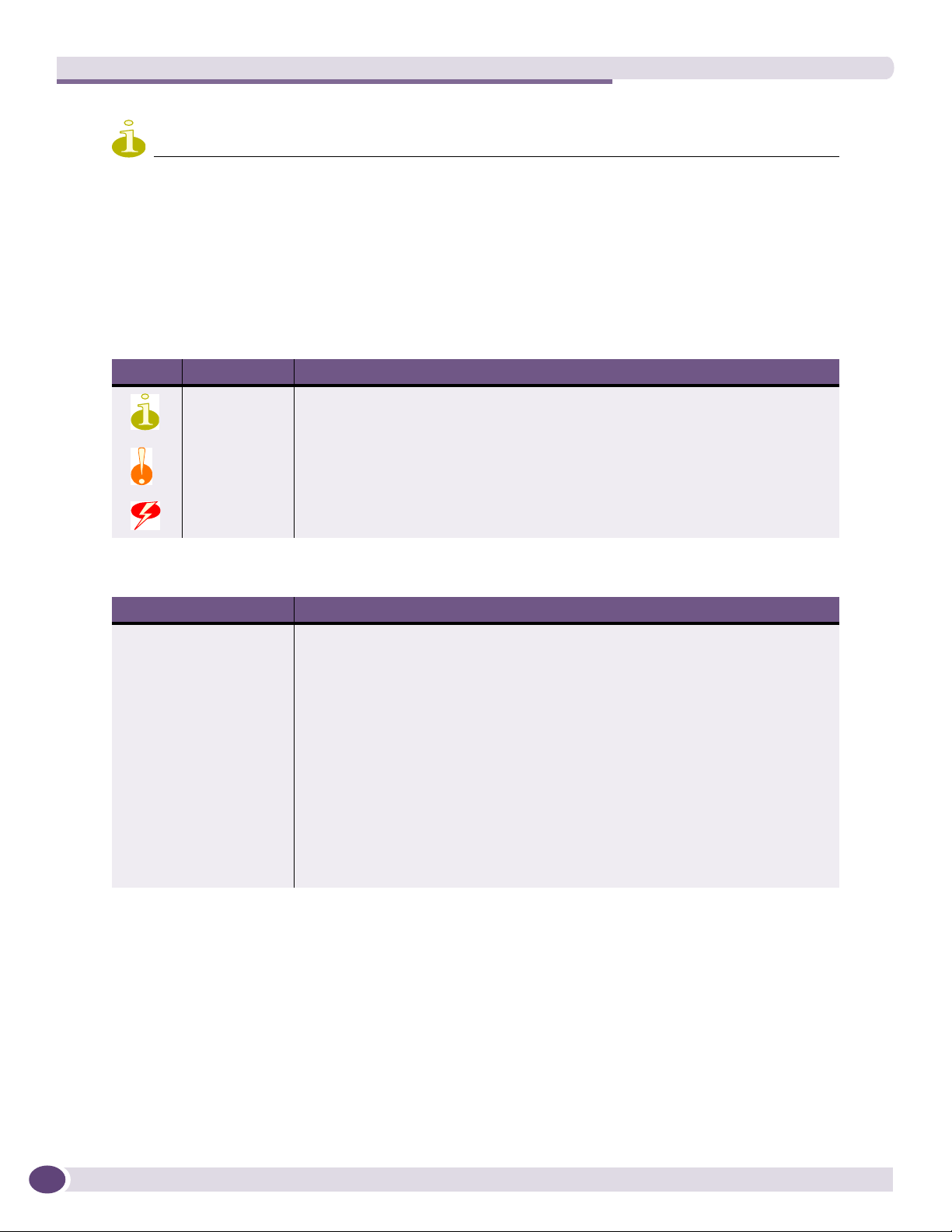
Table 1: Notice Icons
Icon Notice Type Alerts you to...
Note Important features or instructions.
Caution Risk of personal injury, system damage, or loss of data.
Warning Risk of severe personal injury.
Table 2: Text Conventions
Convention Description
Screen displays This typeface represents information as it appears on the screen, or command
syntax.
The words “enter”
and “type”
[Key] names Key names appear in text in one of two ways:
Words in italicized type Italics emphasize a point of information or denote new terms at the place where
When you see the word “enter” in this guide, you must type something, and then
press the Return or Enter key. Do not press the Return or Enter key when an
instruction simply says “type.”
• Referenced by their labels, such as “the Return key” or “the Escape key”
• Written with brackets, such as [Return] or [Esc]
If you must press two or more keys simultaneously, the key names are linked with a
plus sign (+). Example:
Press [Ctrl]+[Alt]+[Del].
they are defined in the text. Book titles are printed in italics.
Related Publications
10
The Extreme Networks ExtremeXOS® switch documentation set includes:
●
ExtremeXOS Concepts Guide
●
ExtremeXOS Command Reference Guide
●
ExtremeXOS Release Notes
●
BlackDiamond® 20808 Switch Hardware Installation Guide
ExtremeXOS Summit Family Switches Hardware Installation Guide

●
BlackDiamond 10808 Switch Hardware Installation Guide
●
BlackDiamond 12800 Series Switches Hardware Installation Guide
●
BlackDiamond 8800 Series Switches Hardware Installation Guide
●
Extreme Networks Pluggable Interface Modules Installation Guide
Documentation for Extreme Networks products is available from the Extreme Networks website at the
following location:
http://www.extremenetworks.com/services/documentation
You can select and download the following Extreme Networks documentation from the Documentation
Overview page:
● Software User Guides
● Hardware Installation Guides
You can find archived user guides for software at:
http://www.extremenetworks.com/services/documentation/swuserguides.asp
You can also find archived installation guides for hardware at:
http://www.extremenetworks.com/services/documentation/hwuserguides.asp
ExtremeXOS Summit Family Switches Hardware Installation Guide
11

Preface
12
ExtremeXOS Summit Family Switches Hardware Installation Guide

1 About the Summit Family Switches


1 Summit Family Switches
This chapter describes the Summit family switches. The chapter includes the following sections:
● Overview of the Summit Switches on page 15
● Summit X150 Series Switches on page 18
● Summit X250e Series Switches on page 23
● Summit X350 Series Switches on page 35
● Summit X450 Series, X450a Series, and X450e Series Switches on page 41
● Summit X650 Series Switches on page 58
Overview of the Summit Switches
The Summit family switches are compact enclosures 1.75 inches high (1 U). They provide 24 or 48
high-density copper or fiber optic ports operating at speeds up to 10 Gbps, with combination
copper/fiber uplink ports. PoE connections and options for adding 10-Gbps or 100 Gbps uplink
connections are available on some models. Many Summit switches include high-speed stacking
interfaces that allow you to connect up to eight Summit switches into a single SummitStack
™
management entity. Summit models are available for AC or DC power connection; all Summit switches
make provision for redundant power supplies. Most models have connections for optional external
redundant power supplies; the Summit X650 series switches provide two bays for pluggable power
supplies.
Tab le 3 and Ta bl e 4 list the Summit switch series and summarize the features available in each series.
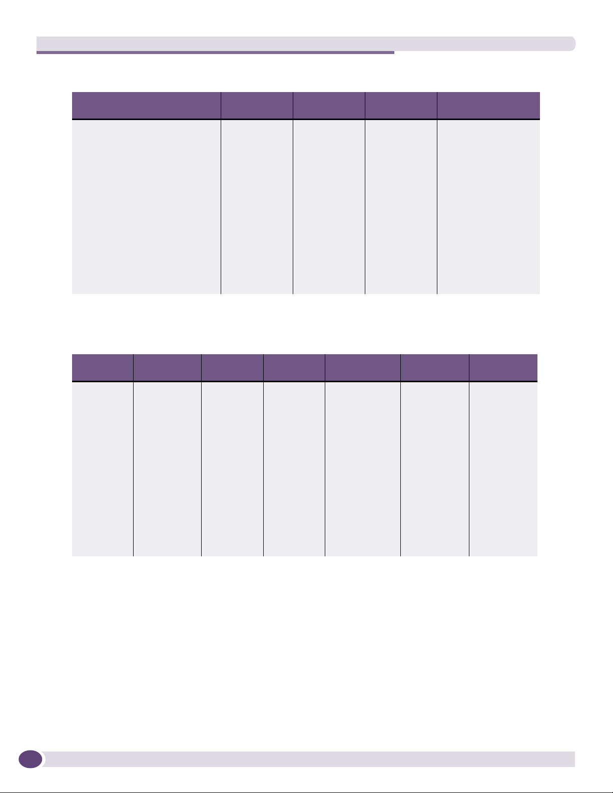
Table 3: Summit Switch Features—Summit X150, X250e, and 350 Series
Summit X150
Feature
Maximum autonegotiating
10/100BASE-TX ports
Maximum autonegotiating
10/100/1000-BASE-TX ports
Maximum 1-Gbps Ethernet ports
(SFP)
Maximum 10-Gbps Ethernet ports — 2 2
SummitStack support No Yes No
Total switching capacity 8.8–17.6 Gbps 48.8–97.6 Gbps 128–256 Gbps
Redundant power Yes (external) Yes (external) Yes (external)
DC power available No Yes Yes
Power over Ethernet (802.3af) Yes Yes No
Series
26 or 50 26 or 50 —
2 24 or 48 24 or 48
2 2 4
Summit X250e
Series
Summit 350
Series
ExtremeXOS Summit Family Switches Hardware Installation Guide
15
Summit Family Switches
Table 4: Summit Switch Features—Summit X450, X450a, X450e, and X650 Series
Feature
Maximum autonegotiating
Summit X450
Series
— — — —
Summit X450a
Series
Summit X450e
Series
Summit X650 Series
10/100BASE-TX ports
Maximum autonegotiating
24 or 48 24 or 48 24 or 48 —
10/100/1000-BASE-TX ports
Maximum 1-Gbps Ethernet ports
4 4 4 4
(SFP)
Maximum 10-Gbps Ethernet ports
(XFP, XENPAK, SFP+)
2 2 2 24 (default)
32 (with VIM1-10G8X)
SummitStack support Yes Yes Yes Yes
Total switching capacity 128–256 Gbps 128–256 Gbps 128–256 Gbps 488–680 Gbps
Redundant power Yes (external) Yes (external) Yes (external) Yes (hot-swappable)
DC power available No Yes No No
Power over Ethernet (802.3af) Yes Yes Yes No
Tab le 5 shows the switch models in each Summit series.
Table 5: Summit Family Switches
Summit X150
Series
Summit
X150-24t
Summit
X150-24p
Summit
X150-48t
Summit X250e
Series
Summit
X250e-24t
Summit
X250e-24tDC
Summit
X250e-24p
Summit
X250e-24x
Summit
X250e-24xDC
Summit
X250e-48t
Summit
X250e-48p
Summit X350
Series
Summit
X350-24t
Summit
X350-48t
Summit X450
Series
Summit
X450-24t
Summit
X450-24x
Summit X450a
Series
Summit
X450a-24t
Summit
X450a-24tDC
Summit
X450a-24x
Summit
X450a-24xDC
Summit
X450a-48t
Summit
X450a-48tDC
Summit X450e
Series
Summit
X450e-24p
Summit
X450e-48p
Summit X650
Series
Summit
X650-24t
Summit
X650-24x
16
Refer to the following sections for specific hardware details about each series:
● Summit X150 Series Switches on page 18
● Summit X250e Series Switches on page 23
● Summit X350 Series Switches on page 35
● Summit X450 Series, X450a Series, and X450e Series Switches on page 41
● “Summit X650 Series Switches” on page 58
ExtremeXOS Summit Family Switches Hardware Installation Guide

NOTE
See the ExtremeXOS Concepts Guide and the ExtremeXOS Command Reference Guide for feature-specific
information about the Summit switches and for information regarding switch configuration.
Combination Ports and Failover
Summit family switches provide two or four uplink ports implemented as combination ports that pair a
copper port using RJ-45 connectors with an optical port using LC connectors. The copper port operates
as an autonegotiating 10/100/1000BASE-T port. The optical port allows Gigabit Ethernet uplink
connections through Extreme Networks small form factor pluggable (SFP) interface modules. See the
individual switch descriptions for the port numbers of the combination ports on each switch model.
Summit family switches support automatic failover from an active fiber port to a copper backup or
from an active copper port to a fiber port. If one of the uplink connections fails, the Summit uplink
connection automatically fails over to the second connection. To set up a redundant link on a
combination port, connect the active 1000BASE-T and fiber links to both the RJ-45 and SFP interfaces
of that port.
Gigabit Ethernet uplink redundancy on the Summit family switches follows these rules:
● With both the SFP and 1000BASE-T interfaces connected on a combination port, only one interface
can be activated. The other is inactive.
● If only one interface is connected, the switch activates the connected interface.
● The switch determines whether the port uses the fiber or copper connection based on the order in
which the connectors are inserted into the switch. When the switch senses that an SFP and a copper
connector are inserted, the switch enables the uplink redundancy feature. For example, if you first
connect copper ports 25 and 26 on a Summit XX250e-24t switch, and then insert SFPs into ports 25
and 26, the switch assigns the copper ports as active ports and the fiber ports as redundant ports.
Hardware determines when a link is lost and swaps the primary and redundant ports to maintain
stability. After a failover occurs, the switch keeps the current port assignment until another failure
occurs or a user changes the assignment using the CLI. For more information about configuring
automatic failover on combination ports, see the ExtremeXOS Concepts Guide.
ExtremeXOS Summit Family Switches Hardware Installation Guide
17

Summit Family Switches
Summit X150 Series Switches
The Summit X150 series switches provide 24 or 48 fixed 10/100BASE-T Ethernet ports that deliver
high-density copper connectivity for 2.4 Gbps or 4.8 Gbps. Models are available with PoE and without
PoE. Each Summit X150 series switch has two combination ports that provide 10/100/1000 BASE-T or
SFP connectivity for 2 Gbps of copper or fiber connectivity. A serial console port on the front panel
allows you to connect a terminal and perform local management. On the back of the switch, an Ethernet
management port can be used to connect the system to a parallel management network for
administration. Alternatively, you can use an Ethernet cable to connect this port directly to a laptop to
view and locally manage the switch configurations.
The rear panel of the switch provides an AC power input socket and a redundant power connector. The
internal power supply operates from 100 VAC to 240 VAC. The switch automatically adjusts to the
supply voltage. The redundant power connector allows you to connect the switch to the EPS-160 or
EPS-500 external power supply. When a compatible external power supply is used with the Summit
X150 series switch, the internal and external power supplies are fully fault tolerant and load-sharing.
If one power supply fails, the other power supply will provide sufficient power to operate the switch.
The Summit X150e series switches include the following switches:
● Summit X150-24t Switch
● Summit X150-24p Switch
● Summit X150-48t Switch
18
ExtremeXOS Summit Family Switches Hardware Installation Guide
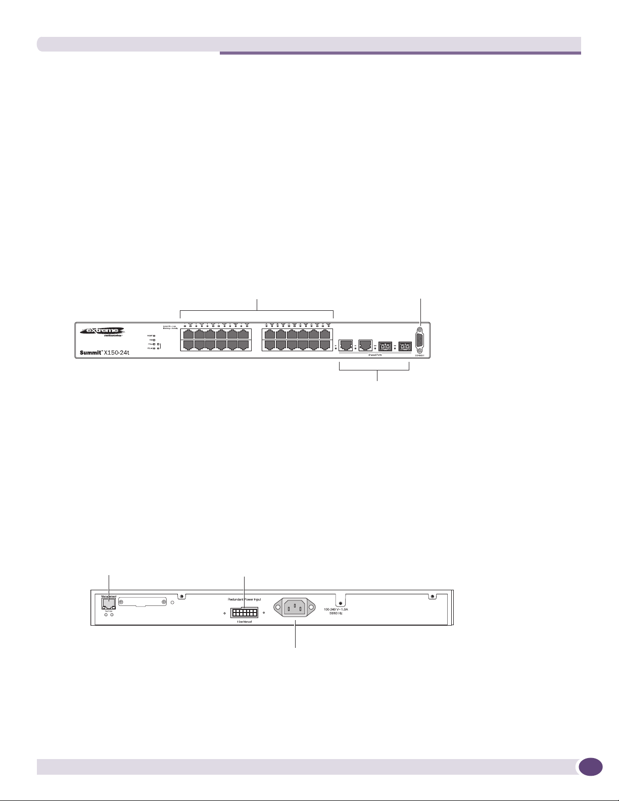
Summit X150-24t Switch
The front panel of the Summit X150-24t switch (Figure 1) includes:
● Twenty-four fixed autosensing 10/100BASE-T ports (ports 1–24) that provide 2.4 Gbps of
high-density copper connectivity
● Two combination ports (ports 25–26) using RJ-45 connectors and SFPs to provide 2 Gbps of copper
or fiber connectivity
For information about SFPs, see the Extreme Networks Pluggable Interface Modules Installation Guide.
● LEDs to indicate port status and switch operating conditions.
For a description of the LEDs and their operation, see “Summit X150 Series Switch LEDs” on
page 22.
● Serial console port used to connect a terminal and perform local management.
Figure 1: Summit X150-24t Switch Front Panel
10/100 Mbps ports
Stack
1
2
port
Combination ports
Console
SH_050B
The rear panel of the Summit X150-24t switch (Figure 2) includes:
● Ethernet management port with associated LEDs
● Redundant power input connector for optional connection to the EPS-160 External Power Module.
See “EPS-160 External Power Module (with EPS-T)” on page 64 for more information. The
connecting redundant power supply cable is shipped with the EPS-160 unit.
● AC power input socket
Figure 2: Summit X150-24t Switch Rear Panel
External power
Management port
supply connection
Power socket
ExtremeXOS Summit Family Switches Hardware Installation Guide
SH_051
19
Summit Family Switches
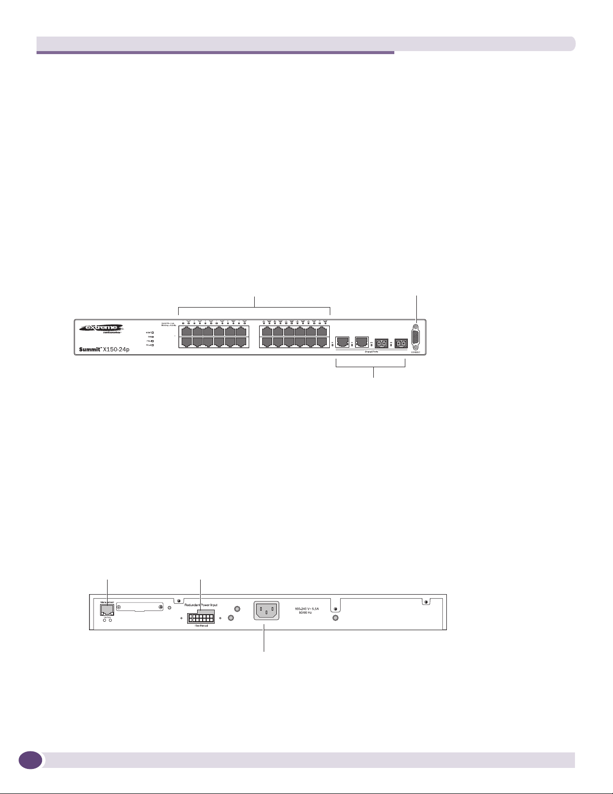
Summit X150-24p Switch
The front panel of the Summit X150-24p switch (Figure 3) includes:
● Twenty-four fixed autosensing 10/100BASE-T PoE ports (ports 1–24). In addition to 4 Gbps of
high-density copper connectivity, these ports also provide a full 15.4 Watts of PoE per port.
● Two combination ports (ports 25–26) using RJ-45 connectors and SFPs to provide 2 Gbps of copper
or fiber connectivity
For information about SFPs, see the Extreme Networks Pluggable Interface Modules Installation Guide.
● LEDs to indicate port status and switch operating conditions.
For a description of the LEDs and their operation, see “Summit X150 Series Switch LEDs” on
page 22.
● Serial console port used to connect a terminal and perform local management.
Figure 3: Summit X150-24p Switch Front Panel
10/100 Mbps ports
Combination ports
Console
port
SH_052A
The rear panel of the Summit X150-24p switch includes:
● Ethernet management port with associated LEDs
● Redundant power input connector for use optional connection to the EPS-500 External Power Supply
(Model No. 10911) with full PoE power support.
See “EPS-500 External Power Supply Unit” on page 65 for more information. The connecting
redundant power supply cable is shipped with the EPS-500 unit.
● AC power input socket
Figure 4: Summit X150-24p Switch Rear Panel
External power
Management port
supply connection
20
Power socket
SH_053
ExtremeXOS Summit Family Switches Hardware Installation Guide
Summit X150-48t Switch
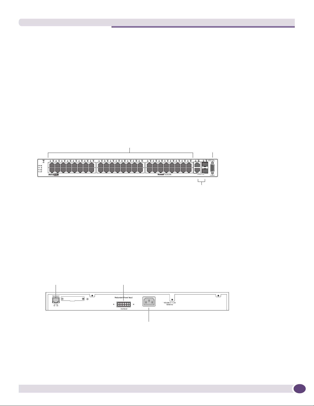
The front panel of the Summit X150-48t switch (Figure 5) includes:
● Forty-eight fixed autosensing 10/100BASE-T ports (ports 1–48) that provide 4.8 Gbps of high-density
copper connectivity
● Two combination ports (ports 49–50) using RJ-45 connectors and SFPs to provide 2 Gbps of copper
or fiber connectivity
For information about SFPs, see the Extreme Networks Pluggable Interface Modules Installation Guide.
● LEDs to indicate port status and switch operating conditions.
For a description of the LEDs and their operation, see “Summit X150 Series Switch LEDs” on
page 22.
● Serial console port used to connect a terminal and perform local management.
Figure 5: Summit X150-48t Switch Front Panel
10/100 Mbps ports Console
port
Combination ports
SH_054A
The rear panel of the Summit X150-48t switch (Figure 6) includes:
● Management port with associated LEDs
● Redundant power input connector for optional connection to the EPS-160 External Power Module.
See “EPS-160 External Power Module (with EPS-T)” on page 64 for more information. The
connecting redundant power supply cable is shipped with the EPS-160 unit.
● AC power input socket
Figure 6: Summit X150-48t Switch Rear Panel
External power
Management port
supply connection
Power socket
SH 055
ExtremeXOS Summit Family Switches Hardware Installation Guide
21
Summit Family Switches
Summit X150 Series Switch LEDs
Tab le 6 lists the of LEDs on the Summit X150 switches, along with their associated colors and meanings.
.
Table 6: LEDs on the Summit X150 Series Switches
Label or Type Color/State Meaning
Front Panel
MGMT Blinking green (fast) Power-on self-test (POST) in progress.
Steady green POST passed. System is booting image.
Blinking green (slow) Normal operation.
Blinking amber Switch diagnostics are running.
or
System is disabled. POST failed or system overheated.
Off No external power attached.
FAN Steady green Normal operation.
Blinking amber Fan failure. Switch will continue to operate unless it
Off No power.
PSU-I
(Internal power
supply)
PSU-E
(External power
supply)
Port number
1 – 24 or 1 – 48
Port number
25, 26 or 49, 50
(Shared ports)
Additional Port LED Meanings for PoE Switch: Summit X150-24p
All front-panel ports Steady green Link OK; port is not powered.
Steady green Normal operation.
Blinking amber Failure.
Off No power.
Steady green Normal operation.
Blinking amber Failure.
Off No external power attached.
Steady green Link is OK.
Blinking green Port is transmitting packets.
Off Link is not present.
Steady green Link is OK.
Blinking green Activity.
Off Link is not present.
Steady amber Link is OK; port is powered; no traffic.
Blinking green Link is OK and transmitting packets; port is not
Blinking amber Link is OK and transmitting packets; port is powered.
Slow blinking amber No link or disabled port; port is powered.
Alternating amber
and green
Off Port is not powered, has no link, or is disabled.
overheats.
or
Port is disabled.
or
Port is disabled.
powered.
Port has a power fault.
22
ExtremeXOS Summit Family Switches Hardware Installation Guide

Table 6: LEDs on the Summit X150 Series Switches (Continued)
Label or Type Color/State Meaning
Rear Panel
Management Port Right LED:
Steady green
Left LED:
Blinking green
Both LEDs off Link is not present.
Link is OK.
Activity.
Summit X250e Series Switches
The Summit X250e series switches provide 24 or 48 Ethernet ports that deliver high-density fast
Ethernet connectivity using fixed 10/100/1000BASE-T ports or installable small form pluggable (SFP)
optical modules. Fixed-port models are available either with or without PoE. Each Summit X250e series
switch has two combination ports that provide 10/100/1000 BASE-T or SFP connectivity for 2 Gbps of
copper or fiber connectivity. A serial console port on the front panel allows you to connect a terminal
and perform local management. An Ethernet management port can be used to connect the system to a
parallel management network for administration. Alternatively, you can use an Ethernet cable to
connect this port directly to a laptop to view and locally manage the switch configurations.
On the back of the switch, two high-speed stacking ports allow you to combine multiple units into a
single SummitStack
™
management entity. The rear panel also provides an AC or DC power input socket
and a redundant power connector. (See specific switch descriptions for more information about the
power options.) The switch automatically adjusts to the supply voltage. The redundant power connector
allows you to connect the switch to the EPS-160, EPS-500, or EPS-150DC external power supply. When a
compatible external power supply is used with the Summit X250e series switch, the internal and
external power supplies are fully fault tolerant and load-sharing. If one power supply fails, the other
power supply will provide sufficient power to operate the switch.
The Summit X250e series switches include the following switches:
● Summit X250e-24t Switch
● Summit X250e-24tDC Switch
● Summit X250e-24p Switch
● Summit X250e-24x Switch
● Summit X250e-24xDC Switch
● Summit X250e-48t Switch
● Summit X250e-48tDC Switch
● Summit X250e-48p Switch
● Summit X250e-48p-TAA Switch
NOTE
The Summit X250e-48p-TAA switch is compliant with the Trade Agreements Act (TAA). Functionally, it is completely
equivalent to the Summit X250e-48p switch. In the descriptions that follow, references to the Summit X250e-48p
switch also apply to the Summit X250e-48p-TAA switch.
ExtremeXOS Summit Family Switches Hardware Installation Guide
23
Summit Family Switches
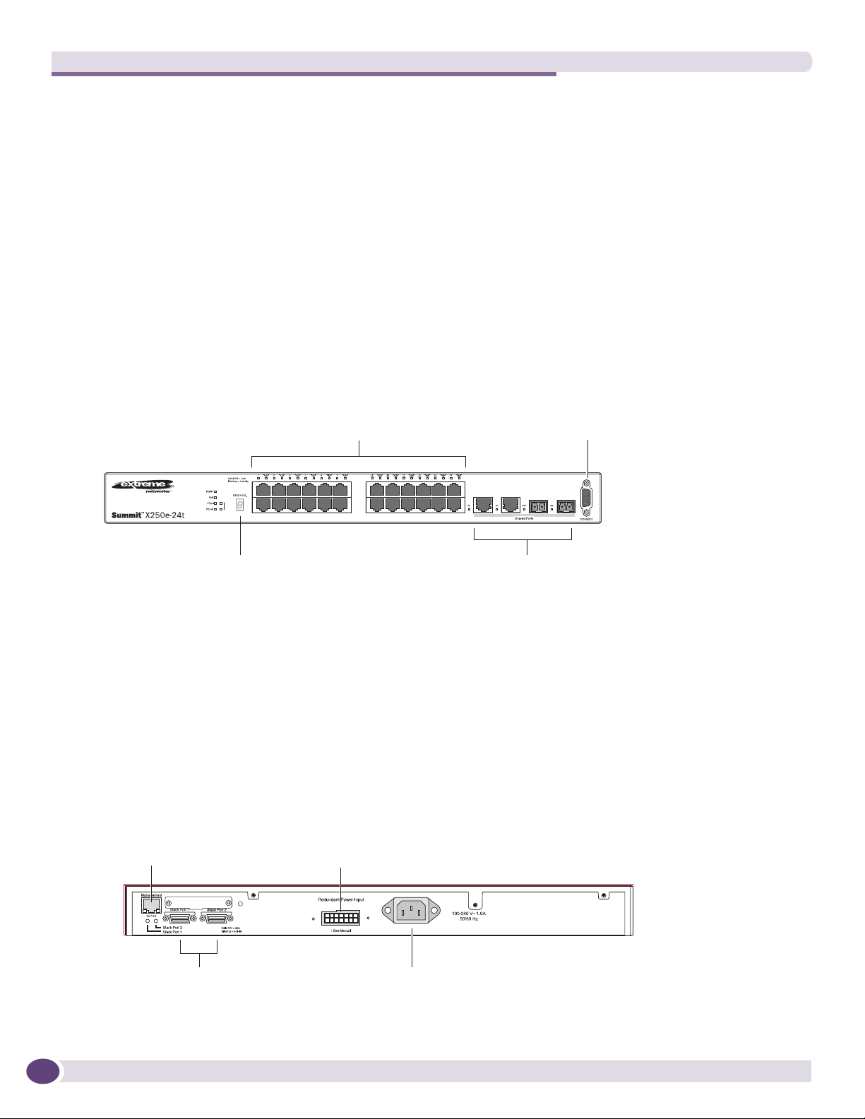
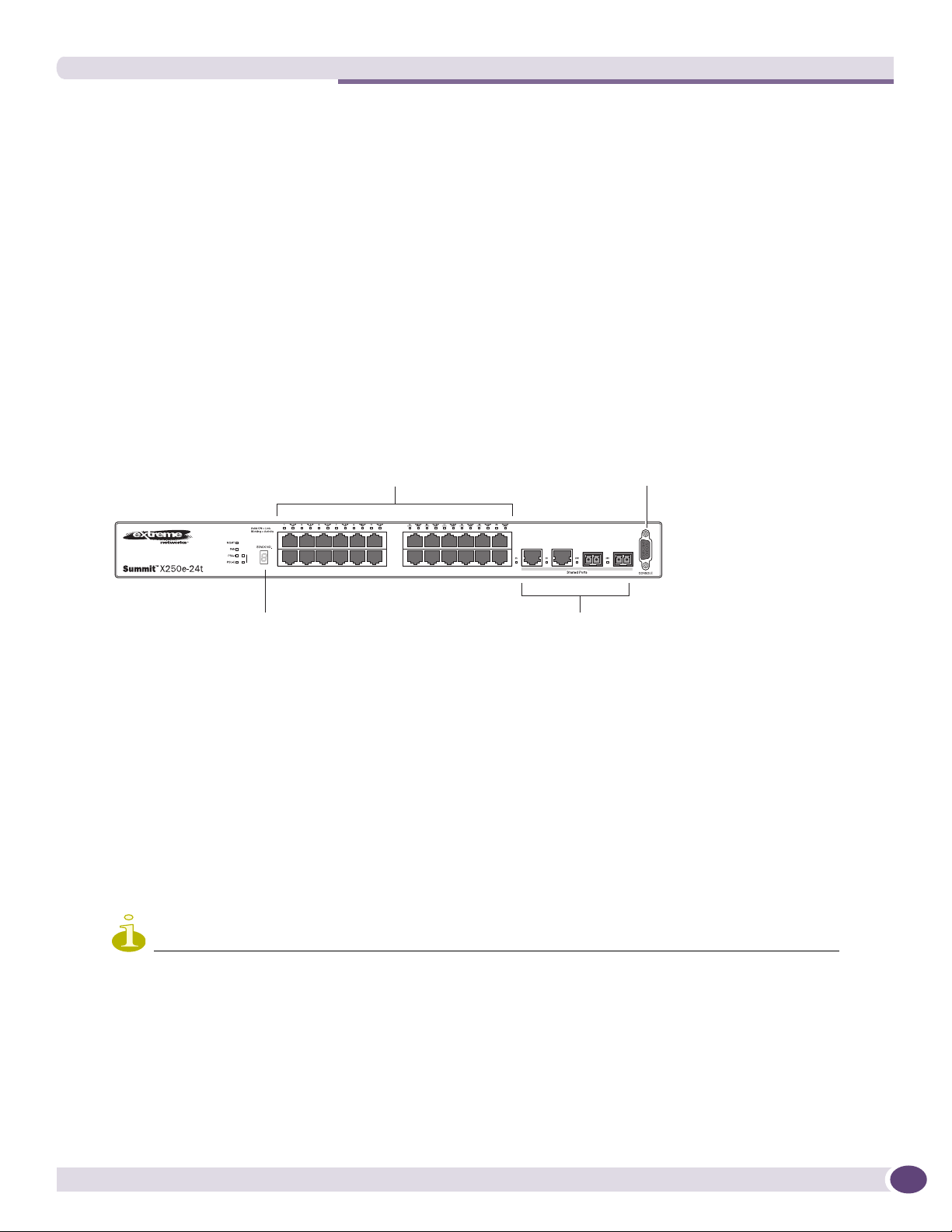
Summit X250e-24t Switch
The front panel of the Summit X250e-24t switch (Figure 7) includes:
● Twenty-four fixed autosensing 10/100BASE-T ports (ports 1–24) that provide 2.4 Gbps of
high-density copper connectivity
● Two combination ports (ports 25–26) using RJ-45 connectors and SFPs to provide 2 Gbps of copper
or fiber connectivity
For information about SFPs, see the Extreme Networks Pluggable Interface Modules Installation Guide.
● LEDs to indicate port status and switch operating conditions.
For a description of the LEDs and their operation, see “Summit X250e Series Switch LEDs” on
page 34.
● Stack number indicator showing the position of this switch in a stacked configuration.
● Serial console port used to connect a terminal and perform local management.
Figure 7: Summit X250e-24t Switch Front Panel
10/100 Mbps ports
Stack
1
2
port
Combination portsStack number indicator
Console
SH_038B
The rear panel of the Summit X250e-24t switch (Figure 8) includes:
● Management port with associated LEDs
● Two high-performance stacking ports with associated LEDs
● Redundant power input connector for optional connection to the EPS-160 External Power Module.
See “EPS-160 External Power Module (with EPS-T)” on page 64 for more information. The
connecting redundant power supply cable is shipped with the EPS-160 unit.
● AC power input socket.
The internal AC power supply operates from 100 VAC to 240 VAC.
Figure 8: Summit X250e-24t Switch Rear Panel
24
Management port
10 Gigabit
stacking ports
External power
supply connection
Redundant Power Input
! See Manual
Power socket
SH_039
ExtremeXOS Summit Family Switches Hardware Installation Guide
Summit X250e-24tDC Switch
The front panel of the Summit X250e-24tDC switch (Figure 33) includes:
● Twenty-four fixed autosensing 10/100BASE-T ports (ports 1–24) that provide 2.4 Gbps of
high-density copper connectivity
● Two combination ports (ports 25–26) using RJ-45 connectors and SFPs to provide 2 Gbps of copper
or fiber connectivity
For information about SFPs, see the Extreme Networks Pluggable Interface Modules Installation Guide.
● LEDs to indicate port status and switch operating conditions.
For a description of the LEDs and their operation, see “Summit X250e Series Switch LEDs” on
page 34.
● Stack number indicator showing the position of this switch in a stacked configuration.
● Serial console port used to connect a terminal and perform local management.
Figure 9: Summit X250e-24tDC Switch Front Panel
Console
DC
10/100 Mbps ports
Stack
1
2
port
Combination portsStack number indicator
SH_057_front_x250e-24tdc
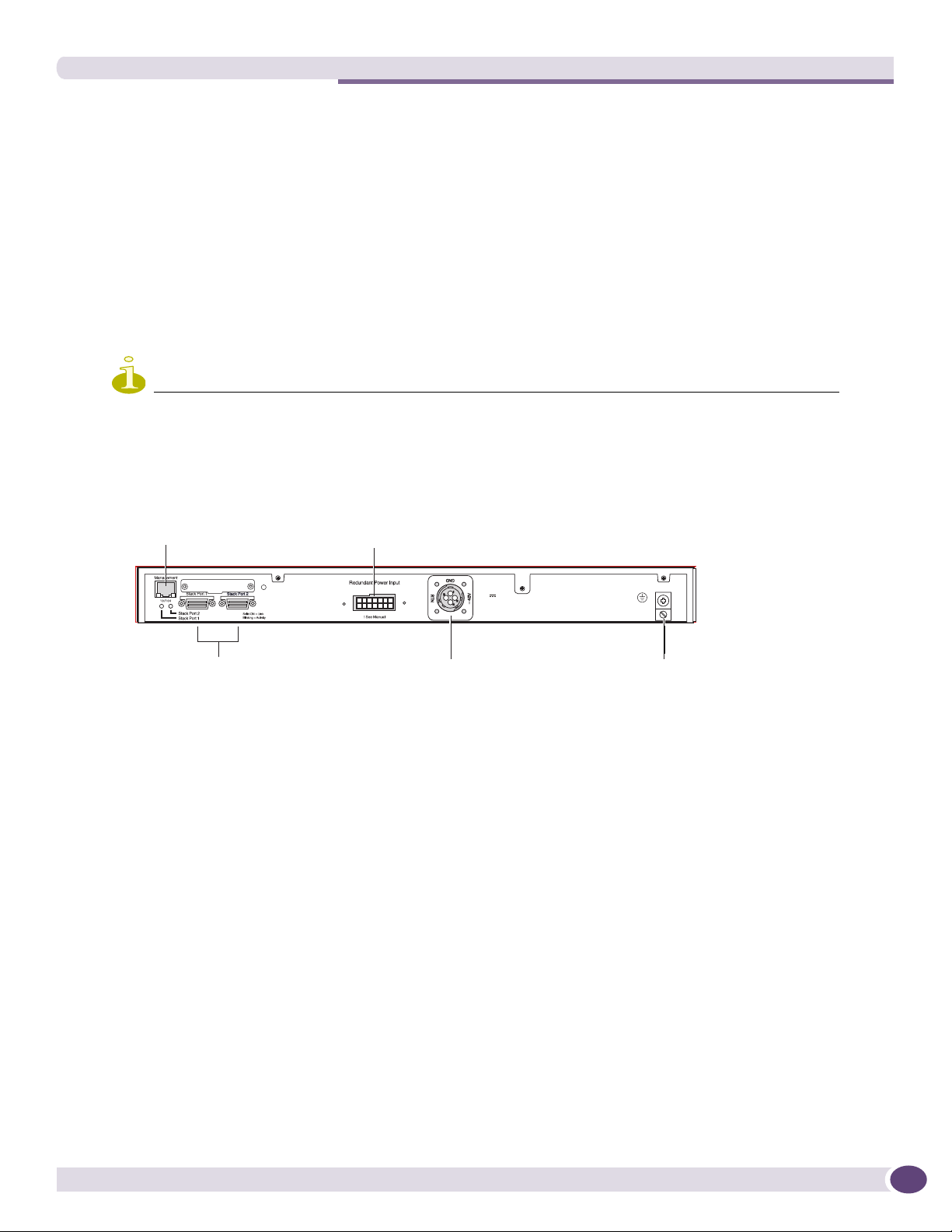
The rear panel of the Summit X250e-24tDC switch (Figure 34) includes:
● Ethernet management port with associated LEDs
● Two high-performance stacking ports with associated LEDs
● Redundant power input connector for optional connection to the EPS-150DC External Power Module
(Model No. 10909).
See “EPS-150DC External Power Module (with EPS-T2)” on page 66 for more information. The
connecting redundant power supply cable is shipped with the EPS-150DC unit.
● DC power input socket
The power supply operates from -36 VDC to -72 VDC.
● Grounding lug
NOTE
For centralized DC power connection, this product is intended to be installed in a restricted access location (such as
a dedicated equipment room, equipment closet, or central office) in accordance with Articles 110-16, 110-17, and
110-18 of the National Electric Code, ANSI/NFPA 70.
ExtremeXOS Summit Family Switches Hardware Installation Guide
25
Summit Family Switches
Figure 10: Summit X250e-24tDC Switch Rear Panel
External power
Management port
supply connection
10 Gigabit
stacking ports
Redundant Power Input
! See Manual
DC power
socket
-48 V
1.5 A Max
Grounding
lug
SH_058_rear_x250e-24t-xdc
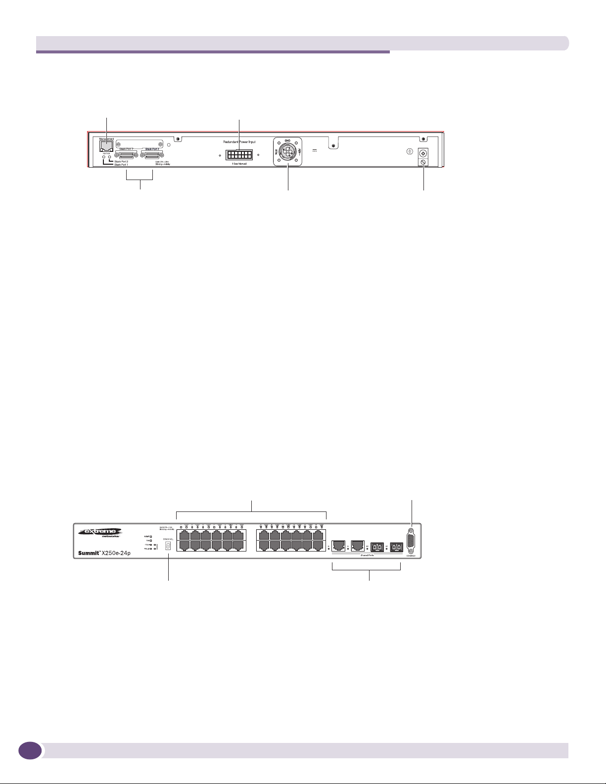
Summit X250e-24p Switch
The front panel of the Summit X250e-24p switch (Figure 11) includes:
● Twenty-four fixed autosensing 10/100BASE-T PoE ports (ports 1–24). In addition to 2.4 Gbps of
high-density copper connectivity, these ports also provide a full 15.4 Watts of PoE per port.
● Two combination ports (ports 25–26) using RJ-45 connectors and SFPs to provide 2 Gbps of copper
or fiber connectivity
For information about SFPs, see the Extreme Networks Pluggable Interface Modules Installation Guide.
● LEDs to indicate port status and switch operating conditions.
For a description of the LEDs and their operation, see “Summit X250e Series Switch LEDs” on
page 34.
● Stack number indicator showing the position of this switch in a stacked configuration.
● Serial console port used to connect a terminal and perform local management.
Figure 11: Summit X250e-24p Switch Front Panel
10/100 Mbps ports
Stack
1
2
Console
port
Combination portsStack number indicator
SH_040B
26
ExtremeXOS Summit Family Switches Hardware Installation Guide
The rear panel of the Summit X250e-24p switch (Figure 12) includes:
● Management port with associated LEDs
● Two high-performance stacking ports with associated LEDs
● Redundant power input connector for use with the EPS-500 External Power Supply (Model No.
10911) with full PoE power support.
See “EPS-500 External Power Supply Unit” on page 65 for more information. The connecting
redundant power supply cable is shipped with the EPS-500 unit.
● AC power input socket.
The internal AC power supply operates from 100 VAC to 240 VAC.
Figure 12: Summit X250e-24p Switch Rear Panel
External power
Management port
supply connection
10 Gigabit
stacking ports
Power socket
SH_041
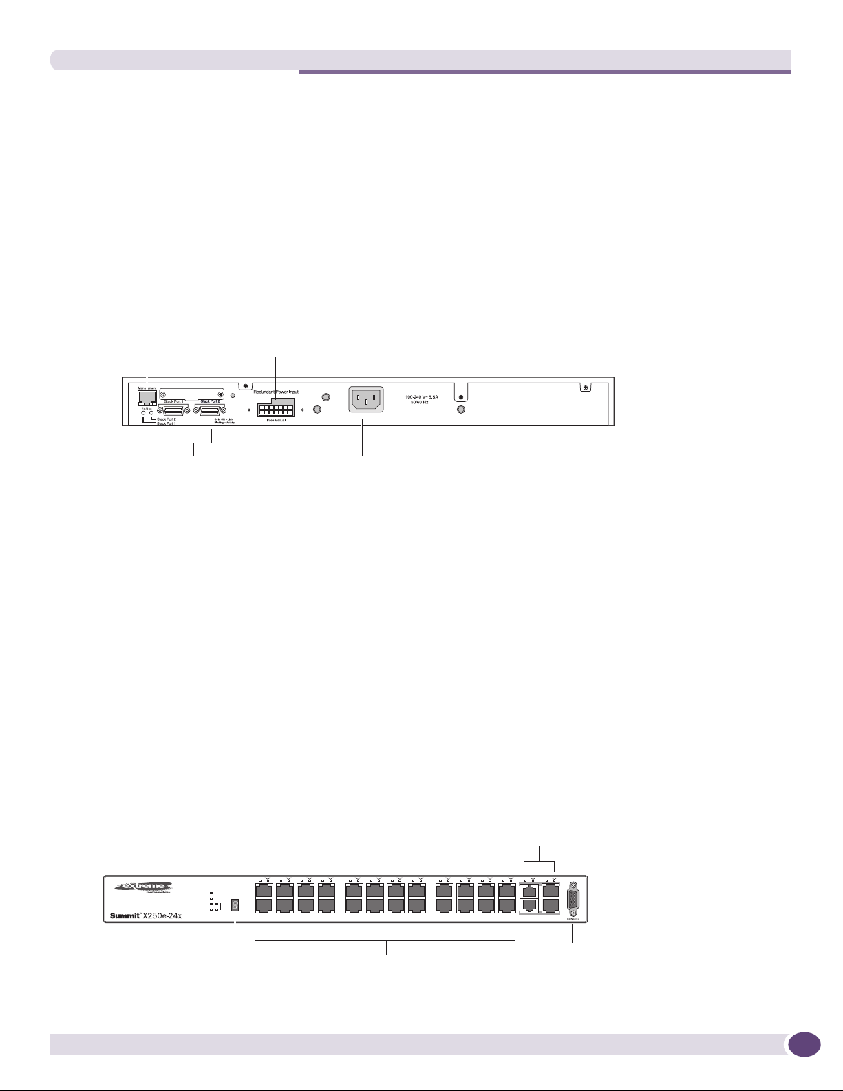
Summit X250e-24x Switch
The front panel of the Summit X250e-24x switch (Figure 7) includes:
● Twenty-four 100BASE-FX ports (ports 1–24) that provide 2.4 Gbps of high-density fiber connectivity
● Two combination ports (ports 25–26) using RJ-45 connectors and SFPs to provide 2 Gbps of copper
or fiber connectivity
For information about SFPs, see the Extreme Networks Pluggable Interface Modules Installation Guide.
● LEDs to indicate port status and switch operating conditions.
For a description of the LEDs and their operation, see “Summit X250e Series Switch LEDs” on
page 34.
● Stack number indicator showing the position of this switch in a stacked configuration.
● Serial console port used to connect a terminal and perform local management.
Figure 13: Summit X250e-24x Switch Front Panel
Combination ports
Stack number
indicator
ExtremeXOS Summit Family Switches Hardware Installation Guide
100BASE-X ports
Console
port
SH_056A
27
Summit Family Switches
The rear panel of the Summit X250e-24x switch (Figure 8) includes:
● Management port with associated LEDs
● Two high-performance stacking ports with associated LEDs
● Redundant power input connector for use with the EPS-160 External Power Module.
See “EPS-160 External Power Module (with EPS-T)” on page 64 for more information. The
connecting redundant power supply cable is shipped with the EPS-160 unit.
● AC power input socket.
The internal AC power supply operates from 100 VAC to 240 VAC.
Figure 14: Summit X250e-24x Switch Rear Panel
External power
Management port
supply connection
Redundant Power Input
! See Manual
10 Gigabit
Power socket
stacking ports
SH_039
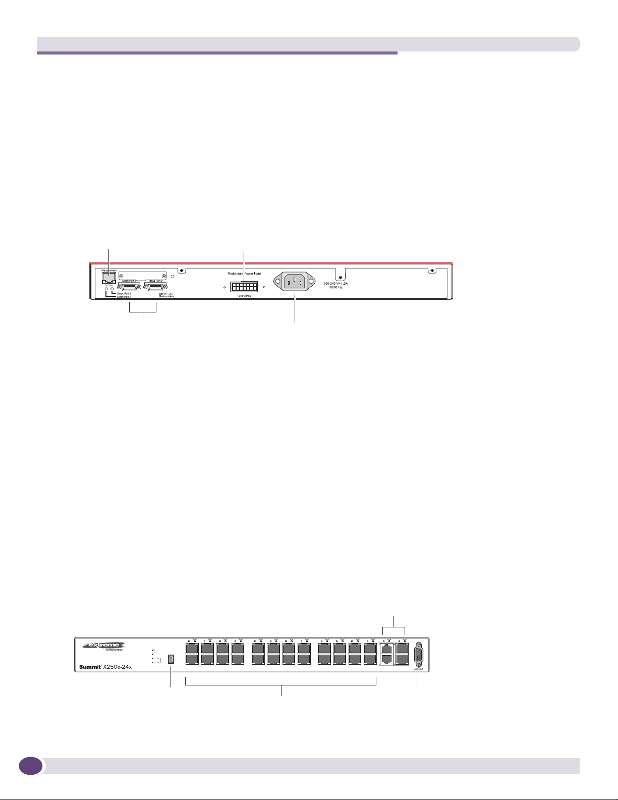
Summit X250e-24xDC Switch
The front panel of the Summit X250e-24xDC switch (Figure 7) includes:
● Twenty-four 100BASE-FX ports (ports 1–24) that provide 2.4 Gbps of high-density fiber connectivity
● Two combination ports (ports 25–26) using RJ-45 connectors and SFPs to provide 2 Gbps of copper
or fiber connectivity
For information about SFPs, see the Extreme Networks Pluggable Interface Modules Installation Guide.
● LEDs to indicate port status and switch operating conditions.
For a description of the LEDs and their operation, see “Summit X250e Series Switch LEDs” on
page 34.
● Stack number indicator showing the position of this switch in a stacked configuration.
● Serial console port used to connect a terminal and perform local management.
Figure 15: Summit X250e-24xDC Switch Front Panel
Combination ports
28
DC
Stack number
indicator
100BASE-X ports
Console
port
SH_059_front_x250e-24xdc
ExtremeXOS Summit Family Switches Hardware Installation Guide
The rear panel of the Summit X250e-24xDC switch (Figure 8) includes:
● Management port with associated LEDs
● Two high-performance stacking ports with associated LEDs
● Redundant power input connector for use with the EPS-150DC External Power Module (Model No.
10909).
See “EPS-150DC External Power Module (with EPS-T2)” on page 66 for more information. The
connecting redundant power supply cable is shipped with the EPS-150DC unit.
● DC power input socket
The power supply operates from -36 VDC to -72 VDC.
● Grounding lug
NOTE
For centralized DC power connection, this product is intended to be installed in a restricted access location (such as
a dedicated equipment room, equipment closet, or central office) in accordance with Articles 110-16, 110-17, and
110-18 of the National Electric Code, ANSI/NFPA 70.
Figure 16: Summit X250e-24xDC Switch Rear Panel
External power
Management port
10 Gigabit
stacking ports
supply connection
Redundant Power Input
! See Manual
DC power
socket
-48 V
1.5 A Max
Grounding
lug
SH_058_rear_x250e-24t-xdc
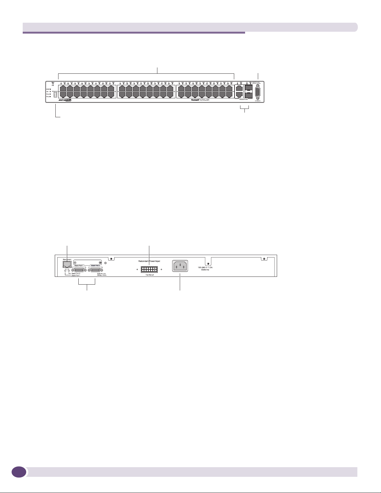
Summit X250e-48t Switch
The front panel of the Summit X250e-48t switch (Figure 17):
● Forty-eight fixed autosensing 10/100BASE-T ports (ports 1–48) that provide 4.8 Gps of high-density
copper connectivity
● Two combination ports (ports 49–50) using RJ-45 connectors and SFPs to provide 2 Gbps of copper
or fiber connectivity
For information about SFPs, see the Extreme Networks Pluggable Interface Modules Installation Guide.
● LEDs to indicate port status and switch operating conditions.
For a description of the LEDs and their operation, see “Summit X250e Series Switch LEDs” on
page 34.
● Stack number indicator showing the position of this switch in a stacked configuration.
● Serial console port used to connect a terminal and perform local management.
ExtremeXOS Summit Family Switches Hardware Installation Guide
29
Summit Family Switches
Figure 17: Summit X250e-48t Switch Front Panel
10/100 Mbps ports Console
port
Stack number indicator
Combination ports
SH_044B
The rear panel of the Summit X250e-48t switch (Figure 18) includes:
● Management port with associated LEDs
● Two high-performance stacking ports with associated LEDs
● Redundant power input connector for optional connection to the EPS-160 External Power Module.
See “EPS-160 External Power Module (with EPS-T)” on page 64 for more information. The
connecting redundant power supply cable is shipped with the EPS-160 unit.
● AC power input socket.
The internal AC power supply operates from 100 VAC to 240 VAC.
Figure 18: Summit X250e-48t Switch Rear Panel
External power
Management port
Stacking ports
supply connection
Power socket
SH_045
30
Summit X250e-48tDC Switch
The front panel of the Summit X250e-48tDC switch (Figure 17):
● Forty-eight fixed autosensing 10/100BASE-T ports (ports 1–48) that provide 4.8 Gps of high-density
copper connectivity
● Two combination ports (ports 49–50) using RJ-45 connectors and SFPs to provide 2 Gbps of copper
or fiber connectivity
For information about SFPs, see the Extreme Networks Pluggable Interface Modules Installation Guide.
● LEDs to indicate port status and switch operating conditions.
For a description of the LEDs and their operation, see “Summit X250e Series Switch LEDs” on
page 34.
● Stack number indicator showing the position of this switch in a stacked configuration.
● Serial console port used to connect a terminal and perform local management.
ExtremeXOS Summit Family Switches Hardware Installation Guide
 Loading...