

Extreme Networks Summit WMScanner User Manual

Summit® WMScanner User Guide
Extreme Networks, Inc.
3585 Monroe Street
Santa Clara, California 95051
(888) 257-3000
(408) 579-2800
http://www.extremenetworks.com
Published: Dec, 2009
Part Number: 100358-00 Rev 01

AccessAdapt, Alpine, Altitude, BlackDiamond, EPICenter, ExtremeWorks Essentials, Ethernet Everywhere, Extreme
Enabled, Extreme Ethernet Everywhere, Extreme Networks, Extreme Standby Router Protocol, Extreme Turbodrive,
Extreme Velocity, ExtremeWare, ExtremeWorks, ExtremeXOS, Go Purple Extreme Solution, ExtremeXOS
ScreenPlay, ReachNXT, Sentriant, ServiceWatch, Summit, SummitStack, Triumph, Unified Access Architecture,
Unified Access RF Manager, UniStack, the Extreme Networks logo, the Alpine logo, the BlackDiamond logo, the
Extreme Turbodrive logo, the Summit logos, and the Powered by ExtremeXOS logo are trademarks or registered
trademarks of Extreme Networks, Inc. or its subsidiaries in the United States and/or other countries.
sFlow is a registered trademark of InMon Corporation.
Specifications are subject to change without notice.
All other registered trademarks, trademarks, and service marks are property of their respective owners.
© 2009 Extreme Networks, Inc. All Rights Reserved.
Summit WMScanner Users Guide2

Table of Contents
Chapter 1: Summit WMScanner Overview..............................................................................................5
System Requirements ..............................................................................................................................................5
Additional Recommendations for 3D Use........................................................................................................5
Installation on XP, Vista 32, Vista 64 .....................................................................................................................6
Preparation........................................................................................................................................................6
Driver Installation.............................................................................................................................................7
For Measurements, use recent Atheros 802.11 chipset LAN cards ..........................................................7
Uninstalling the Measurements Driver....................................................................................................10
Hardware Removal..................................................................................................................................10
Activating Your Software......................................................................................................................................12
Obtaining an Activation Code........................................................................................................................12
Applying Your Activation Code .............................................................................................................13
Determining Your Version......................................................................................................................13
Providing the WMScanner Activation Code..................................................................................................14
Understanding Wireless Network Design..............................................................................................................16
Wireless Network Basics................................................................................................................................16
Steps for Measuring a Wireless Network..............................................................................................................17
Before Getting Started....................................................................................................................................17
Import Site-Specific Drawing.......................................................... ...............................................................17
Measurement and Data Visualization .............................................................................................................18
Exporting Drawings to WMS.........................................................................................................................18
Chapter 2: WMScanner GUI and Menus...............................................................................................19
WMScanner GUI Layout.......................................................................................................................................19
Toolbar Icons..................................................................................................................................................20
Drawing Window - Right Click Menu...........................................................................................................21
Hot Keys.........................................................................................................................................................21
Legend Window...................... ...... ..... .................................................................... ...... ..... ..............................22
WMScanner Menus ...............................................................................................................................................23
File Menu........................................................................................................................................................23
Merging a Color Scheme.........................................................................................................................23
Editing a Color Scheme...........................................................................................................................26
Scale Floor Plan.......................................................................................................................................26
View Menu .....................................................................................................................................................27
View Menu - Building Floor...................................................................................................................28
View Menu - Shade.................................................................................................................................30
Advanced - Set Displayed Drawing Information Dialog........................................................................31
Format Building Menu ...................................................................................................................................33
Edit Sub-menu....... .........................................................................................................................................35
Cut Wall...................................................................................................................................................35
Copy Wall................................................................................................................................................35
Paste Wall......................................... .......................................................................................................35
Erase Wall ...............................................................................................................................................35
Advanced Sub-menu ...............................................................................................................................36
Building Manager....................................................................................................................................36
Summit WMScanner Users Guide 1

Table of Contents
Drawing Limits........................................................................................................................................37
Layer Properties Manager.......................................................................................................................37
Lineweight Settings.................................................................................................................................39
Prune Overlapping Partitions ..................................................................................................................39
Break/Ungroup Entities...........................................................................................................................39
Equipment Menu ............................................................................................................................................40
Measurement Survey Data..............................................................................................................................41
Reports Menu..................................................................................................................................................42
Utilities Menu.................................................................................................................................................49
Project Information..................................................................................................................................50
Setting the Project Workspace.................................................................................................................50
Creating a New Project Workspace..................................................... ....................................................52
Utilities - Geo-Reference Building..........................................................................................................55
Utilities - Drawing Legend......................................................................................................................57
Preferences Dialog..........................................................................................................................................59
Preferences - Files ...................................................................................................................................59
Preferences - Display...............................................................................................................................60
Preferences - Open and Save...................................................................................................................62
Preferences - Plotting ..............................................................................................................................63
Preferences - System...............................................................................................................................64
Preferences - User Preferences................................................................................................................65
Preferences - Drafting..............................................................................................................................66
Preferences - 3D Modelling Tab.............................................................................................................67
Preferences - Selection............................................................................................................................68
Utilities Menu - WMS Configuration......................................................................................................69
Help Menu......................................................................................................................................................70
Chapter 3: Measurement Surveys............................................................................................................73
Taking Measurements.....................................................................................................................................74
Specifying Channel Width..............................................................................................................................77
Setting Measurement Points....................................................................................................................80
Configure Visible Data....................................................... ...... ..... ..........................................................82
Configuring the Authorized List.............................................................................................................84
Manual Data Entry ..................................................................................................................................87
AP Performance Mode............................................................................................................................88
Enforcing Data Transfer and Server-Coupled Measurements........................................................................89
Enforcing Data Transfer Manually..........................................................................................................90
Enforcing Data Transfer Using Server-Coupled Measurements.............................................................90
Starting a Local AP Performance Server Session...................................................................................90
Starting a Remote AP Performance Server Session................................................................................92
Configuration and Statistics Panel...........................................................................................................95
Visualizing Survey Data........................................................................................................ ..............................100
Visualization Panel.......................................................................................................................................101
Configuring Measurement Visualizations....................................................................................................104
Channel Visualization ...........................................................................................................................105
Coverage Visualization .........................................................................................................................106
SNR Visualization.................................................................................................................................107
SSID Visualization................................................................................................................................108
Expected Legacy Data Rate Visualization............................................................................................109
Noise Visualization ...............................................................................................................................110
Noise and Verification of Network Operability....................................................................................112
Hybrid Network Overlap Visualization.................................................................................................112
Channel Width Configuration Visualization.........................................................................................113
Summit WMScanner Users Guide2

Table of Content s
Channel Width Performance.................................................................................................................114
Data Rate Performance..........................................................................................................................115
Verifying Network Coverage ............................. ...... ....................................................................................117
Identifying and Locating Access Points.......................................................................................................117
Verifying the Channel and SSID Settings of Access Points.........................................................................118
Importing Measurement Logfiles........................................................................................................................119
Exporting Measurement Logfiles........................................................................................................................120
Deleting Measurement Data ...................................... ...... ....................................................................................121
Access Point Associations .......................................................... ...... ...................................................................122
Display Measurement Data..................................................................................................................................124
Text Display..................................................................................................................................................125
Set Text Height.............................................................................................................................................126
Graphical Display.........................................................................................................................................126
Show All Markers.........................................................................................................................................130
Reposition and Scale.....................................................................................................................................130
Hide All Markers..........................................................................................................................................130
Configure Markers/Tracklines............................................. ...... ...... .............................................................130
Managing Access Points......................................................................................................................................130
Access Point Placement...................................... ..........................................................................................131
Edit/Remove Access Point ...........................................................................................................................134
Edit ........................................................................................................................................................135
Access Point Colors....................................... ...............................................................................................140
Move Access Point.......................................................................................................................................141
Copy Access Point........................................................................................................................................142
Clone Attributes............................................................................................................................................143
Network Controllers ............................................................................................................................................144
Placing Controllers .......................................................................................................................................144
Editing/Removing Controllers......................................................................................................................145
Edit Controller................................................... ....................................................................................146
Managing Sensors............................................................ ...... ..............................................................................147
Placing Sensors.................................. ...... .....................................................................................................148
Editing/Removing Sensors...........................................................................................................................149
Moving Sensors................................. ...... ...... ................................................................... ............................151
Copying Sensors...........................................................................................................................................151
Managing RFID Devices ....................................................... ..............................................................................152
Placing RFID........................................... ...... ...............................................................................................153
Editing/Removing RFID Devices.................................................................................................................154
Editing RFID ................................................................................................................................................155
Adding/Editing the Antenna.........................................................................................................................157
Reference Tags ....................................................................................................................................................158
Placing Reference Tags ....................................................... ...... ...................................................................158
Editing/Removing Reference-Tag................................................................................................................160
Editing Reference Tag..................................................................................................................................161
Chapter 4: Model Building.....................................................................................................................165
Creating Site-Specific Information Workflow ....................................................................................................165
Format Building Menu.........................................................................................................................................165
Using the Building Wizard...........................................................................................................................166
Add Floor...............................................................................................................................................167
Remove Floor........................................................................................................................................167
Summit WMScanner Users Guide 3

Table of Contents
Up/Down ...............................................................................................................................................167
Format Floor..........................................................................................................................................167
Help Button ...........................................................................................................................................167
Assemble Building................................................................................................................................167
Formatting Floors Using the Floor Formatting Wizard................... ..... ........................................................169
Leave Floor Empty................................................................................................................................171
Sketch Floor Plan .............................................. ....................................................................................171
Making a Copy of a Floor .....................................................................................................................176
Importing an Unformatted File..............................................................................................................176
Import Preformatted File.......................................................... ..... ...... ..................................................180
Editing Floors in an Existing Building Model..............................................................................................181
Rescale Floor.........................................................................................................................................182
Reset Floor Alignment Point.................................................................................................................182
Draw New Partitions .............................................................................................................................182
Convert Partition Type..........................................................................................................................183
Process Unformatted Layers..................................................................................................................183
Clear Floor.............................................................................................................................................183
Snap to Endpoint...................................................................................................................................183
Importing Images Using Insert.....................................................................................................................183
Drawing Zones.....................................................................................................................................................185
Adding Zones..................... ..... ...... .................................................................... ..... ...... .................................187
Editing/Removing Zones..............................................................................................................................188
Toggling the Visibility of the Zones.............................................................................................................190
Defining Zone Colors...................................................................................................................................190
Show/Hide All Zones ...................................................................................................................................192
Editing Partitions and RF Obstructions...............................................................................................................192
Format CAD Drawing ..................................................................................................................................192
Drawing Partitions........................................................................................................................................196
Drawing Tips.........................................................................................................................................199
Change Partition...........................................................................................................................................199
Current Partition Categories.........................................................................................................................200
Editing the Partition Library.........................................................................................................................203
Scale Drawing...............................................................................................................................................208
A Completed Site-Specific Model - Viewing Buildings in 2D and 3D...............................................................208
Toggling Between Floor Views....................................................................................................................208
Viewing In 3D .......................................................... ...... ..... .........................................................................210
Appendix A: Customer Support.............................................................................................................213
Registration..........................................................................................................................................................213
Documentation.....................................................................................................................................................213
Summit WMScanner Users Guide4

1 Summit WMScanner Overview
Summit® WMScanner is a software package that enables you to efficiently measure and visualize
802.11a, 802.11b, 802.11g, and 802.11n network performance. The software utilizes a floor plan map and
a special network driver adapter to allow you to measure, visualize, and archive vital wireless network
information. The powerful visualizations allow you to identify network problems and rogue access
points site-specifically on the map. Not only can you use this software to capture data for post analysis,
but you can also troubleshoot network problems in the field. The data you collect may be saved as a
record of network installation verification or network performance at a given point in time.
Summit WMScanner is easy to get up and running with little or no wireless networking experience. By
reviewing this manual, here are just a few of the features you will learn how to perform:
● Ver i f y n et wo rk co v e r a g e
● Identify and locate rogue and unauthorized access points
● Verify infrastructure access point placement
● Verify access point channel assignments
● Identify noise and interference problems
● Verify infrastructure RFID placement
System Requirements
To run WMScanner, the following computer platform is recommended:
● Intel
● Microsoft
● 1GB RAM
● 500 MB free disk space for installation (10 GB free disk space required for Ray Tracing simulations)
● 1024 x 768 VGA with true color
● Mouse, trackball or compatible pointing device
● Microsoft Internet Explorer 6.0 or higher
● Microsoft Word
● CD-ROM drive
Additional Recommendations for 3D Use
● Operating system: Microsoft
● Processor: 3GHz or greater
● RAM: 2GB or greater
● Hard disk: 2 GB (in addition to the 750 MB required for installation)
● Graphics card: 128 MB or greater, OpenGL-capable workstation-class
®
Pentium IV or greater, 800 MHz or higher
®
Windows XP Service Pack 2 or Windows Vista 32 bit or Windows Vista 64 bit (WoW64).
®
Word 2002 or higher
®
Windows® XP Professional Service Pack 2
Summit WMScanner Users Guide 5

Summit WMScanner Overview
NOTE
For Measurements, use these recent Atheros 802.11 chipset LAN Cards:
● Ubiquity SR71 USB a/b/g/n Adapter
● Netgear 802.11a/b/g Wireless PC Card (model #WAG511)
● Cisco a/b/g Cardbus Adapter (model #AIR-CB21AG-A-K9)
● Ubiquiti Networks SuperRange Cardbus
● D-Link DWA 645 Rangebooster N 650 Notebook Adapter
● AirPcap N 802.11 Wireless Packet Capture Card
Installation on XP, Vista 32, Vista 64
Installing Summit WMScanner is similar to installing any other Windows-based application. Because
this software uses electronic license control, you will be required to obtain an activation code after
installation. In order to install, you will need your installation CD, and some means of transferring files
to your PC or receive an email directly on your PC.
Summit WMScanner is not supported on any Virtual Machine (VM) like VMWare, Virtual Box, Virtaul PC and so on.
Summit WMScanner can be successfully installed on the system, but cannot be executed on it. Any attempt to run
the application on a Virtual Machine results in a warning message and termination of the application.
Preparation
It is very important to perform some preparatory steps so your installation goes smoothly. Read the
QuickStart now, as this contains important (updated) information not included in this manual.
● Windows Service Packs: If your operating system has not been updated with the latest Microsoft
Windows Service Packs, visit the Microsoft support web site, download the service packs and install
them. Your software will work best running under Windows XP, Windows Vista 32, Windows Vista
64 with the most recent updates. These updates are available through www.windowsupdate.com
● Internet Explorer Upgrades: The WININET libraries distributed with Microsoft Internet Explorer 6.0 or
higher are required. If you do not have access to these libraries or Internet Explorer, please contact
Extreme Networks customer support.
● Backing Up Previous Work: If you are upgrading a previous installation of Summit WMScanner,
Extreme Networks recommends that you back up your Workspace folder, Antennas folder, and BOM
folder prior to installation. These folders are located in the root installation directory for your
installed software. The proper procedure to back up your work is detailed in the Quick Start Guide
accompanying the software.
● Administrative Privileges: A user with local machine administrative privileges must install Summit
WMScanner. Non-administrative users may use the software once it has been installed.
Administrator must give write privileges to the non administrative users, to the Summit WMScanner
directory in the Program Files directory.
Before installing the driver on Vista (32 bit), execute the following steps:
1 Run GPEdit.msc (the Group Policy editor).
2 Open Computer Configuration > Administrative Templates > System > Device Installation.
Summit WMScanner Users Guide6

3 Select Treat Drivers Signed by Microsoft the Same as Those Signed by Others and then click Properties.
CAUTION
4 On the settings tab, select Enabled.
5 Open a command window, select Run As Administrator, and run the Group Policy update utility,
GPUpdate.exe, to ensure that the settings are updated on the target system. Ensure that the success
message is shown.
Driver Installation
If the WLAN card has not been previously installed on the computer, then it is recommended to straight away install
the measurements adapter without installing the card manufacturer’s driver. Non-administrative users must have the
write permissions to the directory where the drivers are installed.
For Measurements, use recent Atheros 802.11 chipset LAN cards
● Netgear 802.11a/b/g wireless PC card (model #WAG511)
● Cisco a/b/g Cardbus Adapter (model #AIR-CB21AG-A-K9)
● Ubiquiti Networks SuperRange Cardbus
● D-Link DWA 645 Rangebooster N 650 Notebook Adapter
● AirPcap 802.11 Wireless Packet Capture Card
Follow the instructions below for installing measurements driver for Summit WMScanner.
Driver Installation Instructions:
1 Insert the network adapter into your computer's PCMCIA slot.
2 If the hardware update wizard pops up, press cancel. Double click on Driver Setup.exe present in the
Summit WMScanner\Help\WLAN drivers\ directory.
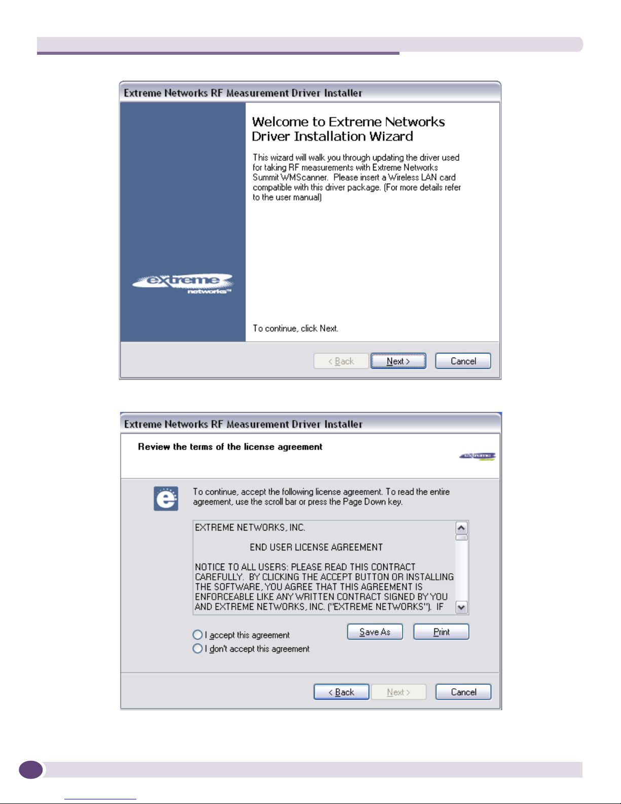
3 The RF Measurement Driver Installer dialog box appears. Select Next.
Summit WMScanner Users Guide 7
Summit WMScanner Overview
4 Choose I accept this agreement. Select Next.
Summit WMScanner Users Guide8
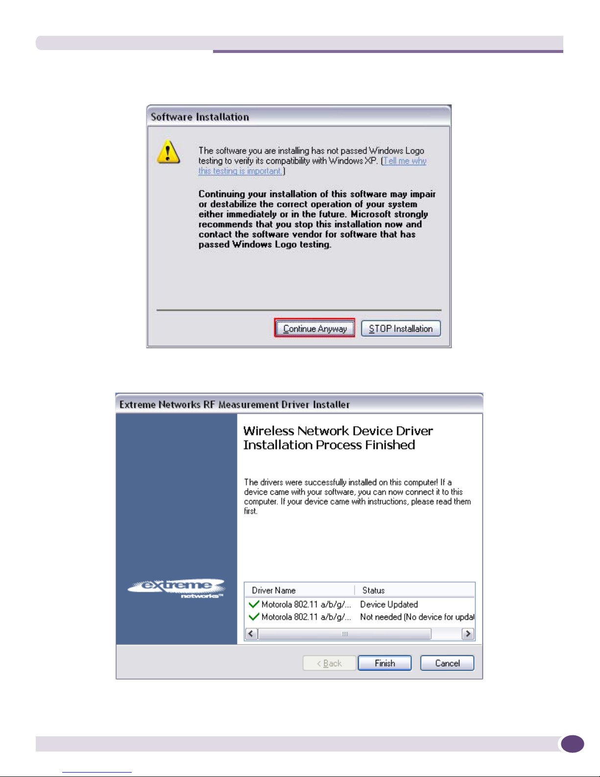
5 If you receive a warning message reporting the software has not passed Windows Logo testing,
choose Continue Anyway.
The driver will now be installed. When the installation finishes, it will notify you that the installation
was successful. If you encounter an error, please contact the Extreme Networks support.
6 An Add remove entry is added which can be used to remove the driver from the system.
Summit WMScanner Users Guide 9
Summit WMScanner Overview
NOTE
CAUTION
If some other driver (say card manufacturer’s driver) has been installed prior to running the installer then, then the
installer will create a backup of the old driver before installing the new driver. The old driver will be restored when
the driver will be uninstalled. The installer may or may not ask for a computer restart.
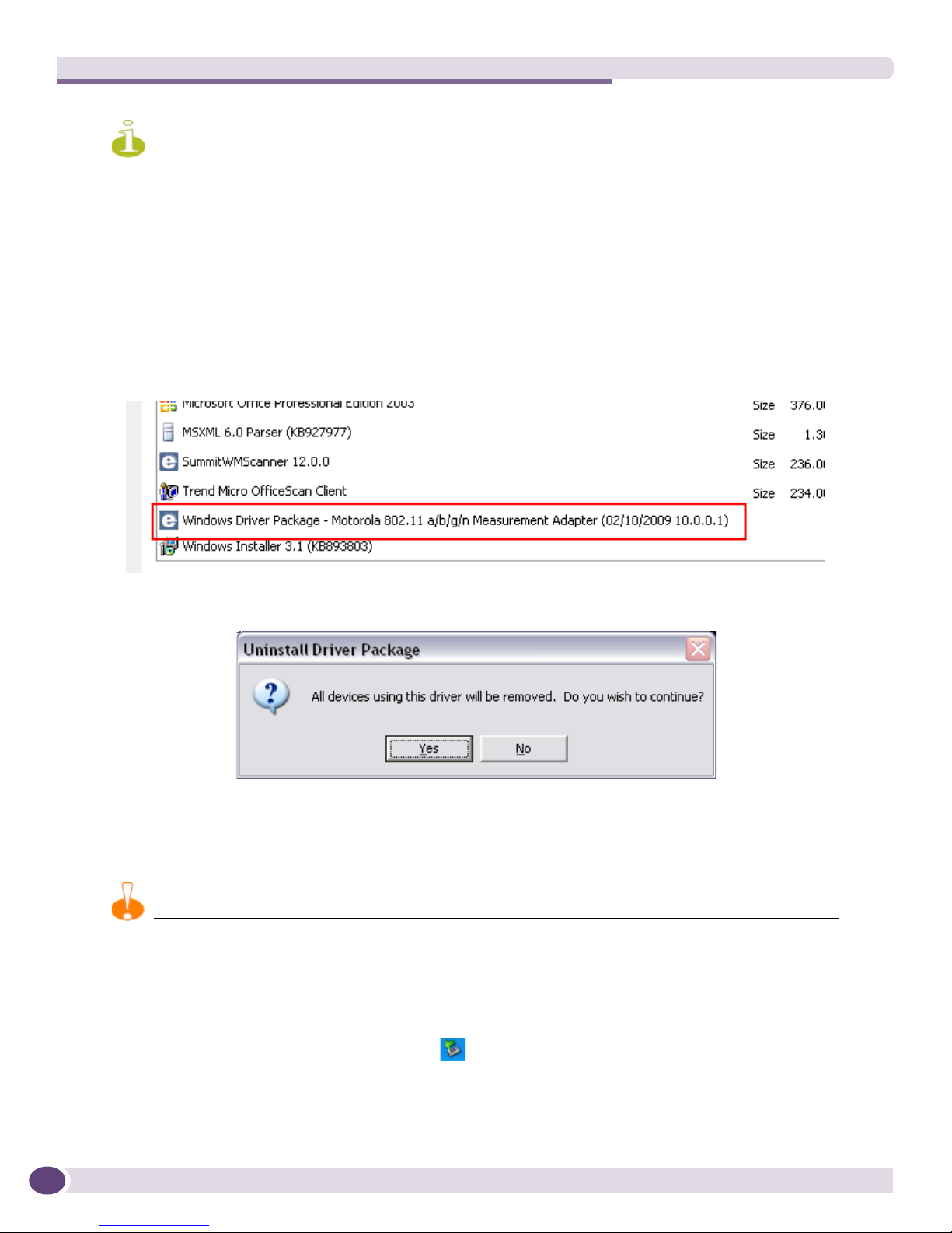
Uninstalling the Measurements Driver
To uninstall the measurements driver:
1 Go to the Windows Control Panel.
2 Click on Add or Remove Programs.
3 Select the Windows Driver Package and Click on Change/Remove.
4 Click Ye s .
The Measurement driver will now be uninstalled.
Hardware Removal
You should only remove the WLAN card adapter from your computer using the following hardware removal process.
Failure to follow this process could cause your computer to crash and may cause loss of data.
To remove hardware:
1 Ensure Summit WMScanner is not running
2 Double click the Safe Hardware Removal icon in the system tray.
3 Choose your Wireless LAN Adapter from the Safely Remove Hardware dialog box. Select Stop.
Summit WMScanner Users Guide10
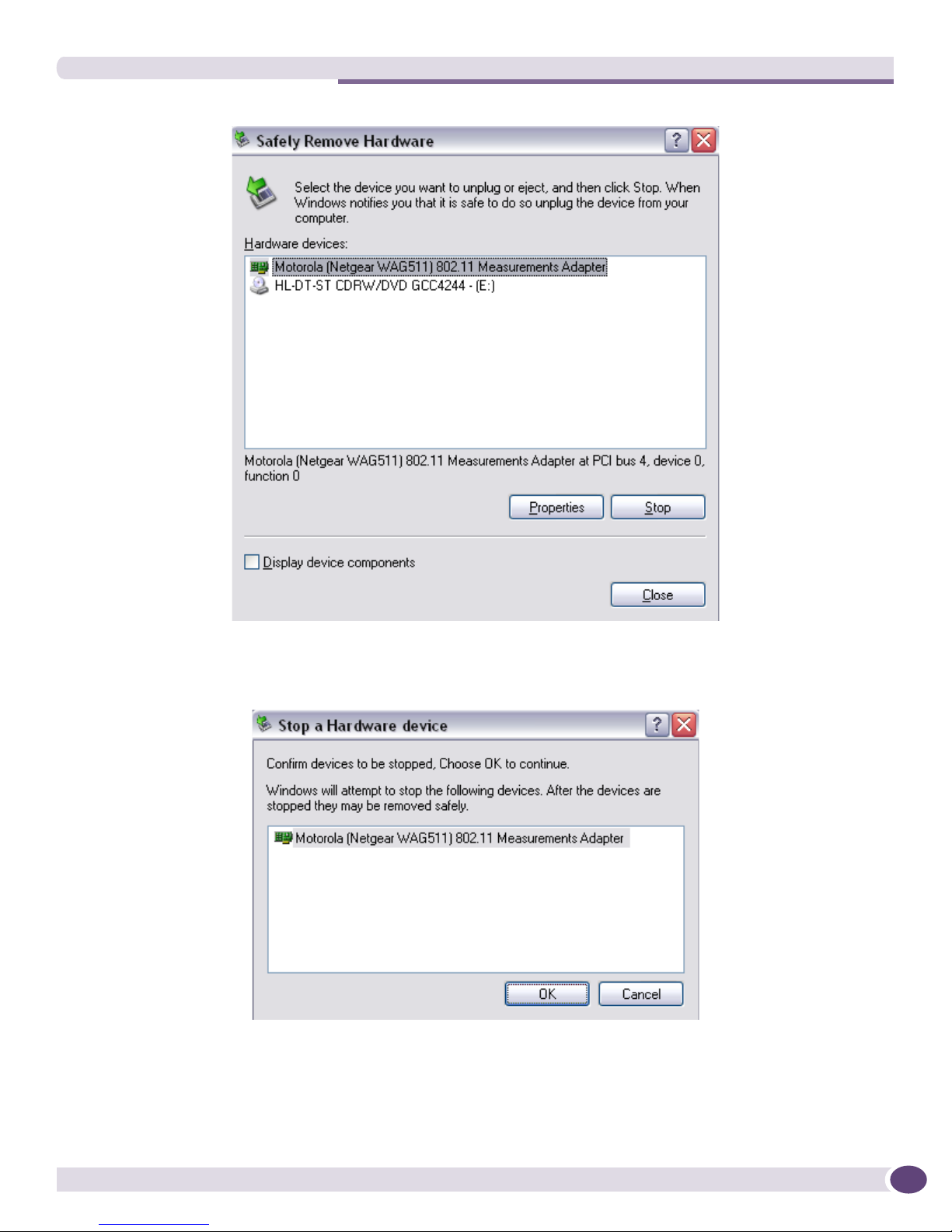
4 Again, select your adapter and select OK to confirm you wish to remove the hardware (this will not
uninstall the driver.
This process simply allows you to safely unplug the adapter from your computer).
You can now remove the WLAN Adapter from your computer. This completes the hardware
removal process.
Summit WMScanner Users Guide 11
Summit WMScanner Overview
NOTE
NOTE
Activating Your Software
For continued use beyond the 14 day trial period, Summit WMScanner requires an activation code, an
activation code must be obtained from Extreme Networks to fully activate your software.
According to the license agreement, your software may only be installed on one PC. License activation codes are tied
to your PC and are non-transferable. Activation codes will not be provided for multiple PCs. Please be aware of this
before requesting an activation code from Extreme Networks. To get the License code you will require a new 16 byte
(string) lock code. The earlier 8 byte (long) lock code will not work.
Obtaining an Activation Code
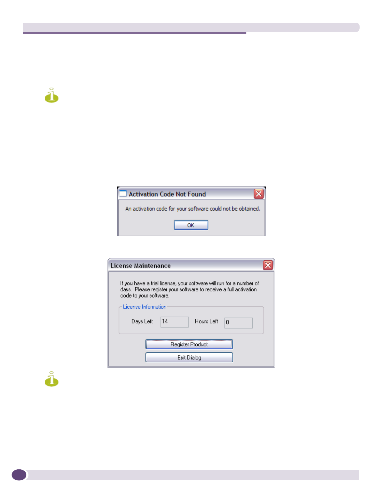
1 When running the software prior to activation, you will be prompted that an activation code could
not be obtained. Click OK to proceed to the License Maintenance Dialog.
2 The License Maintenance dialog displays your current license type and status. Click the Register
Product button to begin the activation process.
The License Maintenance dialog is also accessible by clicking Help > Manage Licenses.
3 To obtain an activation code for your software, complete the activation request form.
Summit WMScanner Users Guide12

Your software includes a 14-day trial license to provide you with a brief grace period. To begin
NOTE
using your software, click Cancel and then click the Exit Update Dialog button.
Applying Your Activation Code
1 An activation code will be returned to you via email as a file attachment. Upon receipt of your
activation code, save the file to an easily-accessible location, preferably your Windows desktop.
2 Access the Update License dialog again by clicking OK when prompted that an activation code
could not be obtained OR by clicking Help > Manage Licenses and clicking the Register Product button:
3 Click the Browse button, locate and select your activation code file, and click Open:
4 Click OK to activate your software. The License Information will update to reflect the type and
remainder of your license.
Activation codes enforce your end user license agreement. Please keep in mind that this electronic license control
mechanism is merely an enforcement method for the terms of this agreement. Regardless of the functions of the
electronic license control, you are bound by the terms of the end user license agreement.
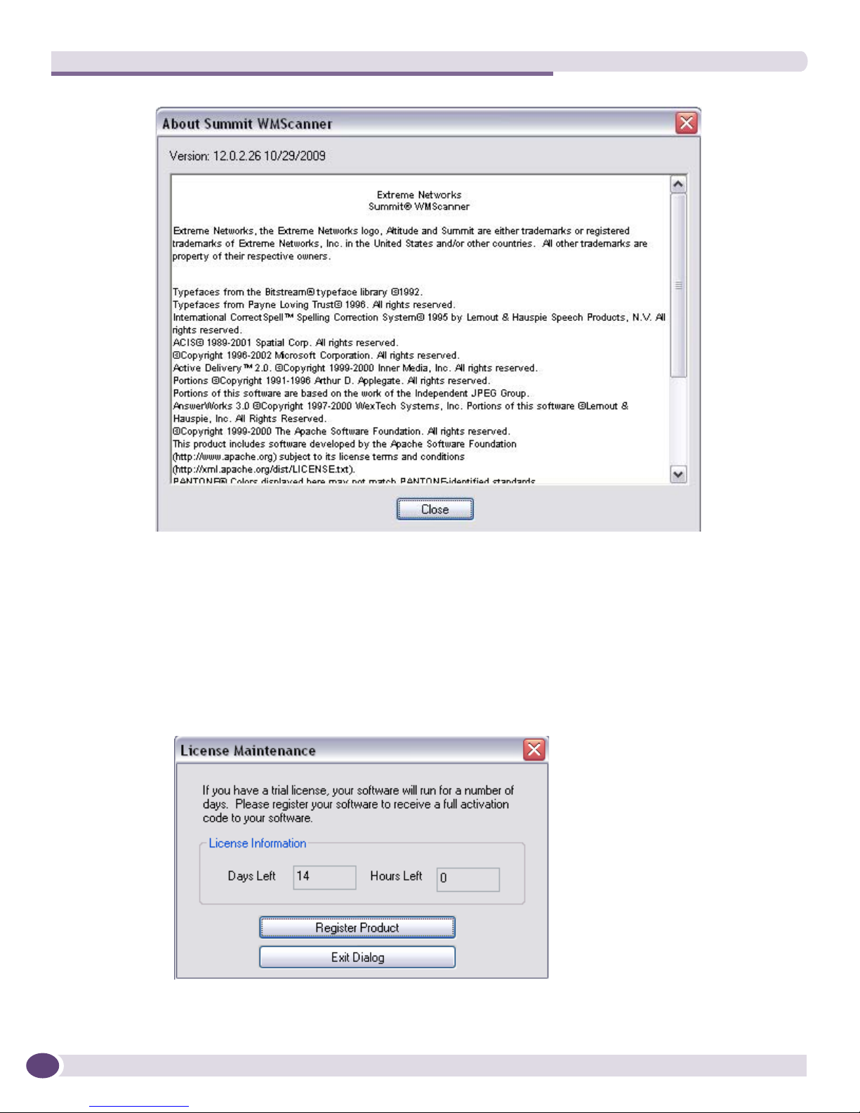
Determining Your Version
To determine the version of your software, click Help > About This Software. Your version number is
displayed in the upper left hand corner of the dialog.
Summit WMScanner Users Guide 13
Summit WMScanner Overview
Providing the WMScanner Activation Code
An annual activation (license) code is required for continued use of Summit WMScanner. Use the
following steps to update the activation (license) code:
1 Launch Summit WMScanner from the desktop icon.
2 Select the Help menu.
3 Click on the Manage Licenses option.
The License Maintenance dialog box displays.
4 Select Register Product.
Summit WMScanner Users Guide14
To obtain the Summit WMScanner software license key:
NOTE
NOTE
a Note the Summit WMScanner Serial/Voucher Number for the software. Summit WMScanner is
part of the Extreme Networks Wireless Management Suite (WMS) software. It uses the same
Serial/Voucher Number as WMS. The WMS Serial/Voucher Number can be found on the
product label located on the outside flap of the WMS CD sleeve.
b Note the MAC address of the PC on which this software should be installed.
c Navigate to the Extreme Networks License Server Website, at
www.extremenetworks.com/extreme/upgrade.htm.
d Select the license for Summit WMScanner.
e Follow the instructions provided to generate and activate the license key.
If you have not already registered this product with Extreme Networks, you can register on the Extreme Networks
website at: http://www.extremenetworks.com/go/productregistration.
5 The license key arrives by email to the customer. Save the attached key to the local drive where the
Summit WMScanner software drive is installed.
The license key is unique to the Client Lock Code. If the Client Lock Code differs from the information provided
to Extreme Networks RF Design & Management Software Customer Support, the Summit WMScanner software
will not activate.
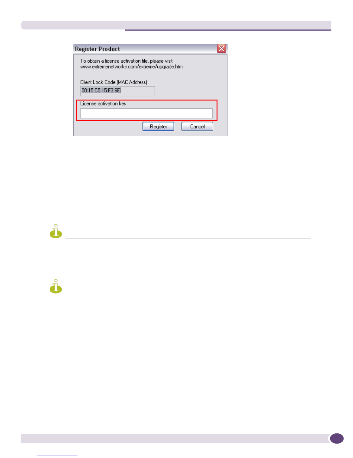
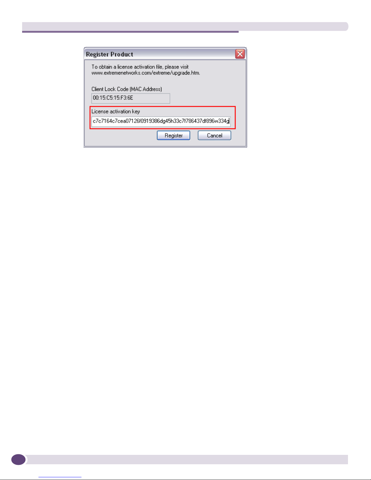
6 Relaunch Summit WMScanner and return to the Register Product screen.
Provide the License activation key.
Summit WMScanner Users Guide 15
Summit WMScanner Overview
7 Click on the Register button.
Summit WMScanner is now ready for use.
Understanding Wireless Network Design
Some general knowledge is important for measuring a 802.11a, b, g, or n wireless communications
network. By no means is this section meant to be complete or comprehensive, but it should serve as a
general introduction for someone who is looking to expand their knowledge of WLANs.
Wireless Network Basics
Measuring wireless signal coverage and placing access points can be a relatively easy task, but
problems hindering the quality of the network quickly multiply when multiple access points are
involved. The proximity of access points to users and to each other, access point channel settings, and
access point power settings can all affect the signal quality and thus wireless network performance.
Several important factors directly affect signal strength. Signal strength near an access point (same room
to several tens of feet away) is considered very strong and is directly related to the access point’s output
power level. Signal strength, however, decreases as you move farther away from the access point
(referred to as attenuation). Another key factor that contributes to diminished signal strength are
obstructions, such as walls and wall-like metal shelving. Keep in mind that different construction
materials attenuate RF signals in different ways.
Summit WMScanner Users Guide16
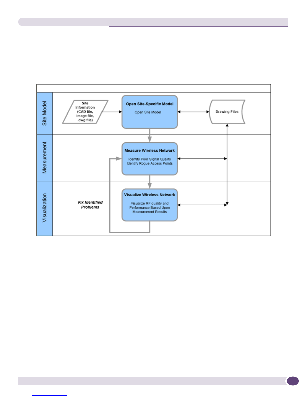
Steps for Measuring a Wireless Network
This section provides you a brief overview of a common suggested workflow using Summit
WMScanner. This workflow describes how most people will work with Summit WMScanner to measure,
visualize measurement results, and troubleshoot WLAN problems. This workflow is intended to give you a
better understanding of how to get started using this software. As your knowledge of this product
matures, you may find more productive ways to use the software as your needs require.
Before Getting Started
There are several things to consider before measuring wireless network performance:
● Do you have access to complete facility drawings in bitmap, jpg, CAD, or Summit WMScanner .dwg
format?
● What are the wireless coverage requirements?
Answers to these questions vary from location to location; however, it is important to consider each of
the above questions throughout the measurement process.
Import Site-Specific Drawing
The first step in wireless network validation is to open the drawing file of the facility or facilities for
which you will be measuring wireless performance. Summit WMScanner requires a facility layout that
properly represents the scale and basic layout of the building. The following primary sources of facility
data may be use in Summit WMScanner:
Summit WMScanner Users Guide 17

Summit WMScanner Overview
● Jpg or Bmp file: Any raster image depicting the building floorplan can be used for surveys within
Summit WMScanner. These images can be drawn by hand in basic image editing software, or they
can be taken from existing floor plans. After importing and scaling, a .jpg or .bmp file is a simple,
efficient method for modeling a building within Summit WMScanner.
● Raw facility CAD file: Most large building facilities are designed in a CAD (Computer Aided Design)
software package. There are many different CAD file formats, but two of the most common are the
.dwg and the .dxf file formats. Summit WMScanner supports opening of these types of CAD files. If
you import these “raw” building files, you will need to scale the drawing, which allows you to
specify the relative dimensions of the building for using during measurement.
● Formatted facility drawing file: This is a specially formatted network design drawing file (with the
same *.dwg extension as some raw CAD drawing files) created within Summit WMScanner. The
drawing file represents building obstructions that affect RF signal coverage. The drawing file
contains information about the location of walls and other obstructions, the type of construction
material, and the wireless network hardware locations and configurations. Some drawing files may
be formatted as empty structures, and not contain access points or any other network hardware
within them.
For each input source, there is a specific Summit WMScanner workflow:
● Raw facility model:
● Create a new drawing or open the image file in Summit WMScanner
● Scale the drawing
● Perform measurement survey
● Formatted drawing file, none, some, or all access points/sensors:
■ Open the .dwg file in Summit WMScanner
■ Perform measurement survey
Measurement and Data Visualization
You can use the Measurement Survey menu within Summit WMScanner to verify signal coverage and
visualize measurement heat maps. Wireless coverage measurement is beneficial for one or more of the
following reasons:
● Allows you to troubleshoot areas where users may be experiencing RF QoS and performance
difficulties.
● Informs you of potential flaws in your original design by determining if the network performs as
originally predicted.
● Reports rogue/pre-existing APs within the facility.
● Enables wireless network fine-tuning.
● Documents the quality of the network as originally installed.
Wireless network measurement is performed using the Measurement Survey menu.
Exporting Drawings to WMS
To send your drawing to WMS you must format your drawings. Summit WMScanner allows you to
format your drawing using the Format Building menu. You can then send this formatted drawing to
WMS.
Summit WMScanner Users Guide18

2 WMScanner GUI and Menus
This chapter provides the information you need to become familiar with the Summit WMScanner
Graphical User Interface (GUI), menu options, utilities, and help options. To help you use Summit
WMScanner efficiently, the chapter is organized around the following structure:
● “WMScanner GUI Layout” - Provides an overview of the Graphical User Interface (GUI), toolbar icons,
and command line window.
● “WMScanner Menus”- Describes the primary Summit WMScanner menus and their options. The File
and View menus are described in detail. The Measurement Survey and Utilities menus are described
from a high-level, while further details are left to the respective chapters.
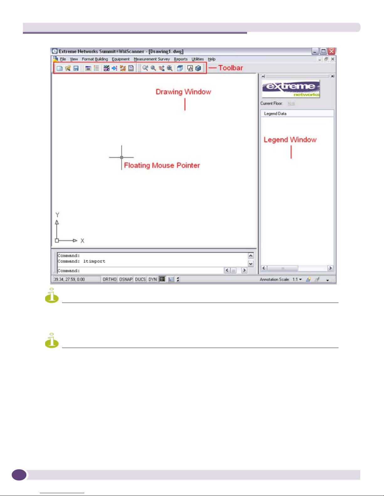
WMScanner GUI Layout
Launch WMScanner from the Windows Start menu by selecting Programs > Summit WMScanner
>Summit WMScanner or by double-clicking the WMScanner icon from your Windows desktop:
:
When the Summit WMScanner GUI opens, note the major features:
Summit WMScanner Users Guide 19
WMScanner GUI and Menus
NOTE
NOTE
To display the Legend Window, selct the Toggle dockable legend icon from the toolbar. For more information, see
“Toolbar Icons” on page 20.
Whenever you change Summit WMScanner’s window size, user preferences, or the project workspace, all settings are
saved upon exiting the tool. These saved settings are restored the next time that you launch Summit WMScanner.
Toolbar Icons
Toolbar icons quick-link to Summit WMScanner commands:
Summit WMScanner Users Guide20

The toolbar icons that follow allow you to manipulate the drawing views:
NOTE
:
Drawing Window - Right Click Menu
Right-clicking anywhere within the drawing window displays the following menu. This menu provides
quick access to the most commonly used functions for viewing the drawing, including real-time pan and
zoom and moving up and down building floors.
Whenever performing tasks within Summit WMScanner, you can press Esc to cancel or abort any command.
Hot Keys
The following hot keys are available to help you move quickly within the drawing window:
● F1 - Mouse and GUI help
● F2 - Place Access Point
● F3 - Refresh screen
● F4 - Move down one floor
● F5 - Move up one floor
Summit WMScanner Users Guide 21
WMScanner GUI and Menus
● F6 - Zoom to drawing extents
● F9 - Go to a specific floor
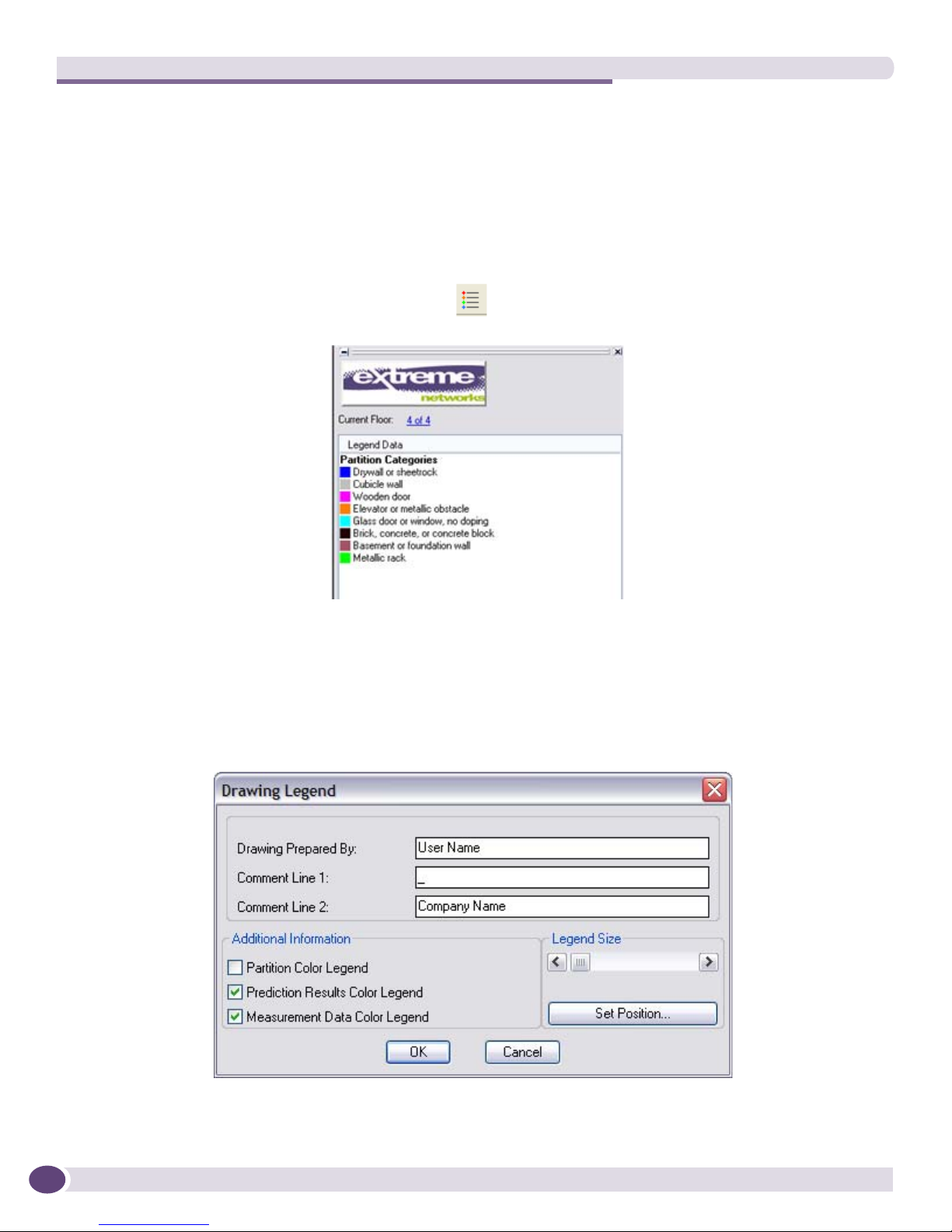
Legend Window
In addition to the legend displayed in the drawing, Summit WMScanner contains a legend window that
displays labels and colors for partition categories and measurement data.
To toggle the legend window on or off, click the button on the standard toolbar. The legend will
remain off (or on) until you toggle it again.
The legend window also displays the current floor of your drawing and allows you to easily change
floors. To do so, left-click on the floor text to navigate to another floor. By default, partition categories is
disabled. Enable partition categories by selecting Utilities > Legend and checking the Partition Color
Legend check box from within the drawing Legend dialog.
You can also toggle the display of the Prediction Results Color Legend and Measurement Data Color Legend
by toggling the appropriate check box.
Summit WMScanner Users Guide22
WMScanner Menus
Summit WMScanner has been designed with an organized menu structure designed to allow you to
quickly access similar features from within the same menu. The following sections provide a brief
overview of each toolbar menu and the functionality that is provided by the submenu commands.
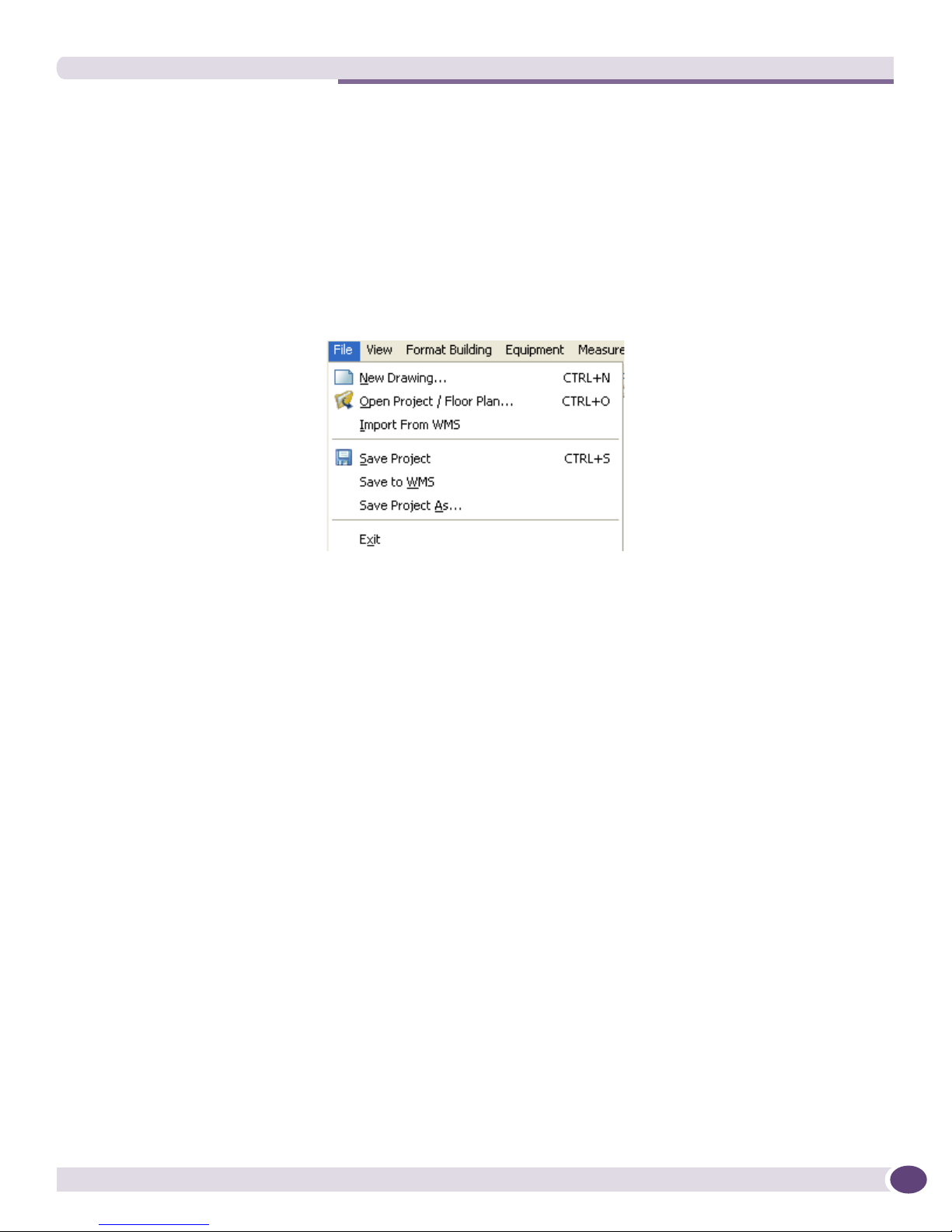
File Menu
The File menu provides the ability to create and open project workspaces, open, and save drawings:
New Drawing Creates a new empty drawing that can be used to construct a floor plan.
Open Project/Floor
Plan
Import From WMS Imports drawing and site information from WMS. If a target WMS Server is not
Save Project Saves the current drawing and measurement run at its existing location with its
Save to WMS Saves the current drawing with all its contents and name information to WMS
Save Project As Saves the current drawing and measurement run with a different name and/or
Exit Exits the Summit WMScanner program. A prompt displays asking if you wish to
Opens a facility drawing (*.dwg) or raw image file (.dxf, .bmp, .pcx, .tif, .jpg,
.bak).
specified, a dialog box appears where the WMS Server IP address, port and
user credentials can be defined to initiate the import operation. Summit
WMScanner authenticates the session while communicating with WMS and
then opens the site file. When the function is complete, the session is closed.
current name.
for interoperation. If a target WMS Server is not specified, a dialog box appears
where the WMS Server IP address, port and user credentials can be defined to
initiate the import operation. Summit WMScanner authenticates the session
while communicating with WMS. When the function is complete, the session is
closed.
file path.
save changes whether or not the drawing has been modified.
Merging a Color Scheme
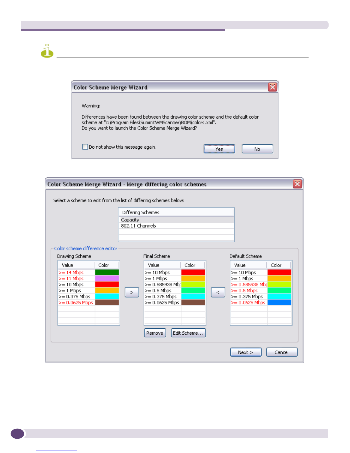
Whenever you open a drawing file, Summit WMScanner compares the color scheme of the drawing
with the default color scheme. The application displays the following warning in case of differences and
allows you to merge the color scheme of the drawing and the default color scheme.
Summit WMScanner Users Guide 23
WMScanner GUI and Menus
NOTE
You can only merge two WMScanner color schemes if you open a drawing.
1 Click Ye s to display the Color Scheme Merge Wizard..
The color scheme merge wizard displays the list of differing schemes as well as the differences
between those schemes. The dialog box displays the conflicting elements of the Default Scheme and
the current scheme used in the drawing (Drawing Scheme), on opposite sides of an automatically
suggested Final Scheme. Initially, the Final Scheme is a combination of the two schemes using the
full list of values from the Default Scheme and all appropriate colors from the Drawing Scheme.
Summit WMScanner Users Guide24
a To add an element to the Final Scheme manually, select the elements from either the Drawing
Scheme or Default Scheme and then click the “>” or “<“ buttons.
b To remove the unnecessary element, select the element and then click the Remove button.
c To edit the Final Scheme manually, click the Edit Scheme... button.
The Edit Scheme dialog box appears, which uses the same system discussed in “Editing a Color
Scheme” on page 26.
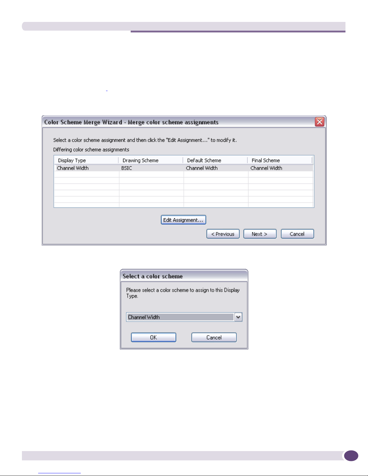
2 Click the Next > button, once you are done with editing the color scheme. If there are differing color
scheme assignments, the Merge color schemes assignments dialog box appears:
a To edit the assignment, select the display type and then click the Edit Assignment... button. The
Select Color Scheme dialog box appears:
b Select the color scheme from the drop down list and click OK. The Select a color scheme dialog box
returns.
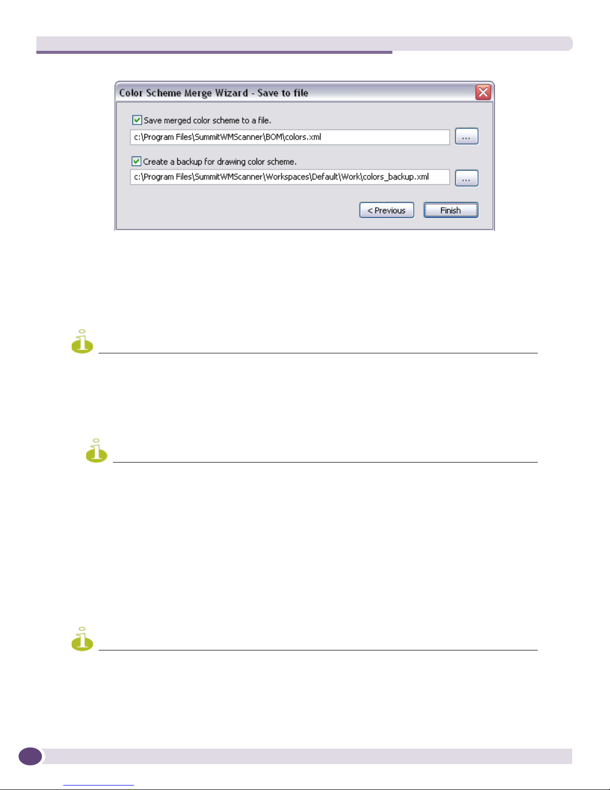
3 Check the Save merged color scheme to a file option to save the file at the location of your choice. Check
the Create backup for drawing color schemes option to create a backup at the location of your choice.
Summit WMScanner Users Guide 25
WMScanner GUI and Menus
NOTE
NOTE
NOTE
4 Click Finish.
Editing a Color Scheme
There are many reasons why a color scheme might need to be changed. Use the following steps when
an existing color scheme needs to be edited:
The following steps may be used to add or remove basic colors from the Color Scheme.
1 Click once on the color scheme for editing.
2 Click the Edit button. The Color Scheme Editor dialog box appears.
3 Double-click the value to be changed. For this demonstration, select 802.11 Channels.
The Color Scheme editor does not always appear the same for all the Scheme Names listed.
4 Change the numeric value.
5 Click on the corresponding color. The basic Color window appears.
6 Select a custom color.
7 Click on the OK button. The Edit Color Scheme window returns.
Scale Floor Plan
The Scale Floor Plan command allows you to scale all entities in the floor plan, providing Summit
WMScanner an accurate representation of distances within the drawing file.
It is important to scale a drawing as it allows you to specify the relative dimensions of the building for using during
measurements.
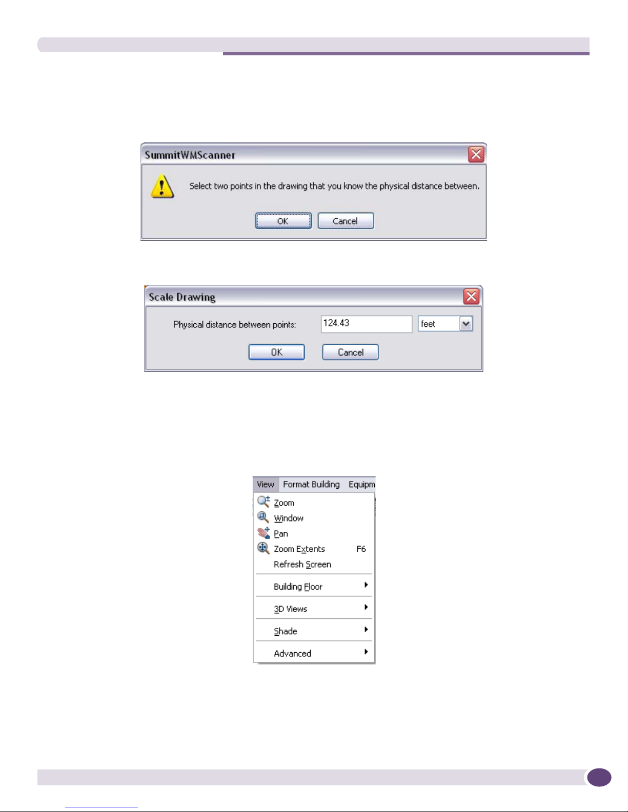
After selecting Scale Floor Plan, left-click in the drawing to select a start point and an end point. When
you are finished, a dialog prompts you to enter the actual physical distance between the two locations.
Summit WMScanner Users Guide26
The appropriate scaling will be applied so that the distance between the points within the drawing
matches the value you enter. If your drawing contains measurement data, you should erase it before
using the scale command.
1 To scale drawing, select File > Scale Floor Plan.
2 Click the OK button. Select the two points in the drawing to know the physical distance between.
The Scale Drawing dialog box appears showing the desired distance.
View Menu
The View menu offers powerful capabilities for displaying your drawing and measurements in a variety
of ways. You can alter the current view of the building environment, refresh, zoom, and pan the
drawing. The View menu also allows you to change the appearance and perspective of measurements.
Zoom Select Zoom to enable real-time zooming. Once real-time zooming is activated,
click and hold the left mouse button while moving the mouse up or down to
zoom in or out, respectively. Press ESC to cancel.
Summit WMScanner Users Guide 27

WMScanner GUI and Menus
Window Zooms a particular area/window in the drawing. Once the window zooming is
Pan Use Pan to move left, right, up or down in your view of the drawing. Pan is an
Zoom Extents Zooms to display the entire drawing. Zooming to the drawing extents will
Refresh Screen Refreshes the display. Use this command when partitions or other drawing data
Building Floor Opens a fly-out menu that include commands for selecting and viewing floors.
3D Views This command allows you to have menu access to the 3D Orbit and Top Views.
Shade The commands under this fly-out menu allows users to view the model in 2D
Advanced >
Display Orde r
Advanced > Set
Displayed Drawing
Information
activated, click and hold the left mouse button while moving the mouse up or
down to zoom in or out. Press ESC to cancel.
alternative to using the scrollbars. When this menu option is selected, the
cursor changes to a hand, and allows the user to drag the screen image around
with the left mouse button. From this mode, the right mouse button brings up
the zoom menu. Press ESC to cancel.
effectively show all of the visible objects in the drawing window.
disappear that should be visible. This is sometimes necessary if a command is
cancelled by hitting the ESC key when the command is partially completed. If
a command is aborted prior to the completion process, the display may be left
in an interim state. The Refresh Screen command will bring the display up to
date.
See “View Menu - Building Floor” on page 28.
wireframe or with shading enabled. See “View Menu - Shade” on page 30.
This command allows you to change the display order of a image that has been
imported into the drawing. Changing the display order will change whether
other entities in the drawing are displayed in front of or behind the image.
Entities that are displayed behind an image may not be visible.
When this command is selected, you are prompted in the text window at the
bottom of the main program window, to select items. These items are the
images whose display order will be changed. Left-click on the image that is
obscuring your partitions, to select it, then right click. You will receive a
prompt in the text window asking how the display order is to be changed.
Typing ‘B’ for back, and hitting the return key will move the partitions to the
back of all other visible entities. Use of the other options, that is, moving
images to the front, or putting them above or below specific partitions, is not
recommended.
This command brings up a Display Options dialog described in “Advanced -
Set Displayed Drawing Information Dialog” on page 31.
View Menu - Building Floor
This menu option is a fly out menu which helps you to adjust the display of different floors in the
building. Use the commands in this menu to control the visibility of a floor, and to specify the “current”
floor. While floors other than the current floor may be made visible, the current floor is the default floor
for many operations in Summit WMScanner
Summit WMScanner Users Guide28
 Loading...