

Extreme Networks Summit WM20 User Manual

Summit WM20 User Guide
Software Ver sion 4.2
Extreme Networks, Inc.
3585 Monroe Street
Santa Clara, California 95051
(888) 257-3000
(408) 579-2800
http://www.extremenetworks.com
Published: January 2008
Part number: 120398-00 Rev 01

AccessAdapt, Alpine, BlackDiamond, EPICenter, ESRP, Ethernet Everywhere, Extreme Enabled, Extreme Ethernet
Everywhere, Extreme Networks, Extreme Standby Router Protocol, Extreme Turbodrive, Extreme Velocity,
ExtremeWare, ExtremeWorks, ExtremeXOS, the Go Purple Extreme Solution, ScreenPlay, Sentriant, ServiceWatch,
Summit, SummitStack, Unified Access Architecture, Unified Access RF Manager, UniStack, UniStack Stacking, the
Extreme Networks logo, the Alpine logo, the BlackDiamond logo, the Extreme Turbodrive logo, the Summit logos,
the Powered by ExtremeXOS logo, and the Color Purple, among others, are trademarks or registered trademarks of
Extreme Networks, Inc. or its subsidiaries in the United States and/or other countries.
Adobe, Flash, and Macromedia are registered trademarks of Adobe Systems Incorporated in the U.S. and/or other
countries. Avaya is a trademark of Avaya, Inc. Merit is a registered trademark of Merit Network, Inc. Internet
Explorer is a registered trademark of Microsoft Corporation. Mozilla Firefox is a registered trademark of the
Mozilla Foundation. sFlow is a registered trademark of sFlow.org. Solaris and Java are trademarks of Sun
Microsystems, Inc. in the U.S. and other countries.
Specifications are subject to change without notice.
All other registered trademarks, trademarks, and service marks are property of their respective owners.
© 2008 Extreme Networks, Inc. All Rights Reserved.
Summit WM20 User Guide, Software Release 4.22

Table of Contents
About this Guide.............................................................................................................................. 9
Who Should Use This Guide .........................................................................................................9
What Is in This Guide ..................................................................................................................9
Formatting Conventions .............................................................................................................10
Documentation Feedback...........................................................................................................10
Safety Information ....................................................................................................................11
Considerations Before Installing............................................................................................11
Installing Power Supply Units...............................................................................................12
Power Input Requirements ...................................................................................................12
Maintenance Safety.............................................................................................................13
General Safety Precautions ..................................................................................................13
Power Supply Cords Selection ..............................................................................................13
Battery Replacement and Disposal ........................................................................................15
Sicherheitshinweise...................................................................................................................16
Hinweise zur Installation......................................................................................................16
Installation von Netzteilen....................................................................................................17
Wartungssicherheit..............................................................................................................17
Allgemeine Sicherheitsvorkehrungen .....................................................................................18
Auswahl der Stromkabel ......................................................................................................18
Austauschen und Entsorgen von Batterien .............................................................................19
Chapter 1: Overview of the Summit WM Controller, Access Points and Software Solution .................. 21
Conventional Wireless LANS.......................................................................................................21
Elements of the Summit WM Controller, Access Points and Software Solution.................................22
Summit WM Controller, Access Points and Software and Your Network...........................................24
Network Traffic Flow............................................................................................................25
Network Security.................................................................................................................26
WM Access Domain Services ................................................................................................28
Static Routing and Routing Protocols ....................................................................................28
Packet Filtering Policy .........................................................................................................29
Mobility and Roaming..........................................................................................................29
Network Availability.............................................................................................................29
Quality of Service (QoS) .......................................................................................................30
System Configuration Overview ...................................................................................................30
Chapter 2: Configuring the Summit WM Controller........................................................................... 33
System Configuration Overview ...................................................................................................34
Performing the First-Time Setup of the Summit WM Controller ......................................................37
Accessing the Summit WM Controller....................................................................................37
Connecting the Summit WM Controller to Your Enterprise Network...........................................41
Applying the Product License Key .........................................................................................41
Setting up the Data Ports .....................................................................................................42
Setting up Static Routes ......................................................................................................45
Setting up OSPF Routing .....................................................................................................47
Summit WM20 User Guide, Software Release 4.2 3

Table of Contents
Filtering at the Interface Level..............................................................................................50
Built-in Port-Based Exception Filters .....................................................................................50
User-Defined Port-Based Exception Filters.............................................................................51
Completing the System Configuration..........................................................................................52
Ongoing Operations of the Summit WM Controller, Access Points and Software...............................53
Chapter 3: Configuring the Wireless AP ..........................................................................................55
Wireless AP Overview.................................................................................................................55
Discovery and Registration Overview............................................................................................56
Wireless AP Discovery..........................................................................................................57
Registration After Discovery..................................................................................................58
Understanding the Wireless AP LED Status............................................................................58
Configuring the Wireless APs for the First Time ............................................................................60
Defining Properties for the Discovery Process .........................................................................60
Connecting the Wireless AP to a Power Source and Initiating the Discovery and Registration Process
63
Adding and Registering a Wireless AP Manually ...........................................................................63
Modifying Wireless AP Settings ..................................................................................................64
Modifying a Wireless AP’s Status ..........................................................................................64
Configuring the Default AP Settings ......................................................................................65
Modifying a Wireless AP’s Properties .....................................................................................68
Modifying the Wireless AP’s Radio Properties.........................................................................70
Setting up the Wireless AP Using Static Configuration ............................................................75
Configuring Dynamic Radio Management.....................................................................................77
Modifying a Wireless AP’s Properties Based on a Default AP Configuration .....................................79
Modifying the Wireless AP’s Default Setting Using the Copy to Defaults Feature..............................79
Configuring APs Simultaneously .................................................................................................80
Performing Wireless AP Software Maintenance.............................................................................81
Chapter 4: WM Access Domain Services ........................................................................................ 85
WM-AD Overview.......................................................................................................................85
Setting up a WM-AD Checklist....................................................................................................86
Topology of a WM-AD ................................................................................................................87
RF Assignment for a WM-AD ......................................................................................................88
Authentication for a WM-AD .......................................................................................................89
Authentication With SSID Network Assignment ......................................................................89
Authentication With AAA (802.1x) Network Assignment..........................................................89
Filtering for a WM-AD ................................................................................................................90
Final Filter Rule ..................................................................................................................91
Filtering Sequence ..............................................................................................................91
Data Protection on a WM-AD—WEP and WPA ..............................................................................92
WM-AD Global Settings .............................................................................................................92
Setting up a New WM-AD...........................................................................................................95
Chapter 5: WM Access Domain Services Configuration.................................................................... 97
Topology for a WM-AD ...............................................................................................................98
Configuring Topology for a WM-AD for Captive Portal ..............................................................99
Configuring Topology for a WM-AD for AAA ..........................................................................105
Saving Your Topology Properties .........................................................................................106
Summit WM20 User Guide, Software Release 4.24

Table of Contents
Assigning Wireless AP Radios to a WM-AD .................................................................................106
Authentication for a WM-AD .....................................................................................................108
Vendor-Specific Attributes .................................................................................................108
Defining Authentication for a WM-AD for Captive Portal ........................................................109
Defining Authentication for a WM-AD for AAA ......................................................................116
Defining MAC-Based Authentication for a WM-AD ................................................................118
Defining Accounting Methods for a WM-AD................................................................................120
Defining RADIUS Filter Policy for WM-ADs and WM-AD Groups ...................................................121
Configuring Filtering Rules for a WM-AD....................................................................................122
Filtering Rules for an Exception Filter .................................................................................123
Defining Non-authenticated Filters......................................................................................124
Filtering Rules for a Filter ID group .....................................................................................128
Filtering Rules for a Default Filter .......................................................................................130
Enabling Multicast for a WM-AD ...............................................................................................132
Configuring Privacy for a WM-AD ..............................................................................................134
Privacy for a WM-AD for Captive Portal ................................................................................134
Privacy for a WM-AD for AAA ..............................................................................................137
Defining a WM-AD With No Authentication ................................................................................140
Defining Priority Level and Service Class for WM-AD Traffic ........................................................141
Defining the Service Class for the WM-AD............................................................................142
Configuring the Priority Override .........................................................................................142
Working with Quality of Service (QoS) .......................................................................................143
QoS Modes .......................................................................................................................143
Configuring the QoS Policy on a WM-AD ....................................................................................145
Bridging Traffic Locally............................................................................................................148
Chapter 6: Availability and Controller Functionality ....................................................................... 151
Availability Overview ................................................................................................................151
Availability Prerequisites ....................................................................................................152
Viewing the Wireless AP Availability Display .........................................................................154
Viewing SLP Activity..........................................................................................................155
Events and Actions During a Failover...................................................................................156
Defining Management Users.....................................................................................................157
Configuring Network Time ........................................................................................................158
Configuring Check Point Event Logging .....................................................................................160
ELA Management Station Events ........................................................................................162
Enabling SNMP ......................................................................................................................162
MIB Support .....................................................................................................................162
Enabling SNMP on the Summit WM Controller .....................................................................163
Using Controller Utilities..........................................................................................................164
Configuring Web Session Timeouts ...........................................................................................166
Chapter 7: Working With Third-Party APs ..................................................................................... 169
Chapter 8: Working With the Summit WM Series Spy .................................................................... 173
Summit WM Series Spy Overview..............................................................................................173
Enabling the Analysis and Data Collector Engines ......................................................................174
Running Summit WM Series Spy Scans.....................................................................................175
Summit WM20 User Guide, Software Release 4.2 5

Table of Contents
Analysis Engine Overview .........................................................................................................176
Working With Summit WM Series Spy Scan Results ...................................................................177
Working With Friendly APs .......................................................................................................179
Viewing the Summit WM Series Spy List of Third-Party APs ........................................................180
Maintaining the Summit WM Series Spy List of APs ...................................................................181
Viewing the Scanner Status Report ...........................................................................................182
Chapter 9: Working With Reports and Displays ............................................................................. 185
Viewing the Displays................................................................................................................185
Viewing the Wireless AP Availability Display .........................................................................186
Viewing Statistics for Wireless APs......................................................................................187
Viewing the System Information and Manufacturing Information Displays ...............................189
Viewing Reports ......................................................................................................................190
Chapter 10: Performing System Maintenance................................................................................ 195
Performing Wireless AP Client Management ...............................................................................195
Disassociating a Client.......................................................................................................195
Blacklisting a client...........................................................................................................196
Resetting the AP to Its Factory Default Settings .........................................................................199
Performing System Maintenance Tasks......................................................................................200
Performing Summit WM Controller Software Maintenance ...........................................................202
Updating Summit WM Controller Software ...........................................................................202
Updating Operating System Software ..................................................................................204
Backing up Summit WM Controller Software ........................................................................206
Restoring Summit WM Controller Software...........................................................................208
Upgrading a Summit WM Controller Using SFTP ..................................................................210
Configuring Summit WM Controller, Access Points and Software Logs and Traces....................211
Viewing Log, Alarm and Trace Messages ..............................................................................211
Glossary ..................................................................................................................................... 217
Networking Terms and Abbreviations.........................................................................................217
Summit WM Controller, Access Points and Software Terms and Abbreviations...............................235
Appendix A: Summit WM20 Controller.......................................................................................... 237
Hardware Specifications ..........................................................................................................237
Summit WM20 Controller Panels ..............................................................................................238
Console Port for Summit WM20 Controller.................................................................................238
Summit WM20 Controller LED Indicators ..................................................................................239
Summit WM20 Controller’s LEDs........................................................................................239
Summit WM20 Controller LED States and Corresponding System States.................................240
Appendix B: Regulatory Information.............................................................................................. 241
Summit WM20 .......................................................................................................................241
Safety Standards...............................................................................................................241
EMI/EMC Standards ..........................................................................................................242
Environmental Conditions ..................................................................................................242
Environmental Operating Conditions for Summit WM100/1000, Summit WM200/2000, and Alti-
tude 350-2 AP..................................................................................................................243
Altitude 350-2 Int. AP (15958) AP, Altitude 350-2 Detach. AP (15939).....................................244
Summit WM20 User Guide, Software Release 4.26

Table of Contents
United States - FCC Declaration of Conformity Statement .....................................................244
Conditions Under Which a Second Party May Replace a Part 15 Unlicensed Antenna ..............246
European Community ........................................................................................................247
Certifications of Other Countries ...............................................................................................253
Altitude 350-2 Int. AP (15958) and Altitude 350-2 Detach. (15939) Access Points.....................253
Optional Approved 3rd Party External Antennas....................................................................254
Antenna Diversity ..............................................................................................................254
Optional 3rd Party External Antennas for the United States ...................................................254
Optional 3rd Party External Antennas for Canada..................................................................258
Optional 3rd Party External Antennas the European Community.............................................262
Index.......................................................................................................................................... 267
Summit WM20 User Guide, Software Release 4.2 7

Table of Contents
Summit WM20 User Guide, Software Release 4.28

About this Guide
This guide describes how to install, configure, and manage the Summit® WM Controller, Access Points,
and Software.
Who Should Use This Guide
This guide is a reference for system administrators who install and manage the Summit WM Controller,
Access Points and Software system.
Any administrator performing tasks described in this guide must have an account with full
administrative privileges.
What Is in This Guide
This guide contains the following:
● “About this Guide”, describes the target audience and content of the guide, the formatting
conventions used in it, and how to provide feedback on the guide.
● Chapter 1, “Overview of the Summit WM Controller, Access Points and Software Solution,”
provides an overview of the product, its features and functionality.
● Chapter 2, “Configuring the Summit WM Controller,” describes how to perform the installation,
first-time setup and configuration of the Summit WM Controller, as well as configuring the data
ports and defining routing.
● Chapter 3, “Configuring the Wireless AP,” describes how to install the Wireless AP, how it discovers
and registers with the Summit WM Controller, how to view and modify the radio configuration, and
how to enable Dynamic Radio Frequency Management.
● Chapter 4, “WM Access Domain Services,”provides an overview of WM Access Domain Services
(WM-AD), the mechanism by which the Summit WM Controller, Access Points and Software
controls and manages network access.
● Chapter 5, “WM Access Domain Services Configuration,” provides detailed instructions in how to
configure a WM-AD, its topology, authentication, accounting, RADIUS policy, multicast, filtering
and privacy. Both Captive Portal and AAA types of WM-AD are described.
● Chapter 6, “Availability and Controller Functionality,”describes how to set up the features that
provide availability in the event of a controller failover.
● Chapter 7, “Working With Third-Party APs,” describes how to use the Summit WM Controller,
Access Points and Software features with third-party wireless access points.
● Chapter 8, “Working With the Summit WM Series Spy,” explains the security tool that scans for,
detects and reports on rogue APs.
● Chapter 9, “Working With Reports and Displays,” describes maintenance activities, such as software
upgrades on both the Summit WM Controller and the Wireless AP. This chapter also includes
information on the logs, traces, reports and displays available.
Summit WM20 User Guide, Software Release 4.2 9

About this Guide
● “Glossary” contains a list of terms and definitions for the Summit WM Controller and the Wireless
AP as well as standard industry terms used in this guide.
● Appendix A, “Summit WM20 Controller,” provides a reference on the LED displays and their
significance.
● Appendix B, “Regulatory Information,” provides the regulatory information for the Summit WM20
Wireless LAN Controllers and the Altitude 350-2 Int. AP (15958) and Altitude 350-2 Detach. (15939)
Access Points (APs).
Formatting Conventions
The Summit WM Controller, Access Points and Software documentation uses the following formatting
conventions to make it easier to find information and follow procedures:
● Bold text is used to identify components of the management interface, such as menu items and
section of pages, as well as the names of buttons and text boxes.
● For example: Click Logout.
● Monospace font is used in code examples and to indicate text that you type.
● For example: Type https://<wm20-address>[:mgmt-port>]
● The following symbols are used to draw your attention to additional information:
NOTE
Notes identify useful information that is not essential, such as reminders, tips, or other ways to perform a task.
WARNING!
Warnings identify information that is essential. Ignoring a warning can adversely affect the operation of your
equipment or software.
Documentation Feedback
If you have any problems using this document, please contact your next level of support:
● Customers should contact the Extreme Networks Technical Assistance Center (TAC).
When you call, please have the following information ready. This will help us to identify the document
that you are referring to.
● Title: Summit WM20 User Guide, Software Release 4.2
● Part Number: 120398-00 Rev 01
Summit WM20 User Guide, Software Release 4.210

Safety Information
Safety Information
WARNING!
Read the following safety information thoroughly before installing Extreme Networks products. Failure to follow this
safety information can lead to personal injury or damage to the equipment.
Installation, maintenance, and removal of a controller, chassis, or any of its components must be
performed by trained and qualified service personnel only! Trained and qualified service personnel are
persons having appropriate technical training and experience necessary to be aware of the hazards to
which they are exposed in performing a task and of measures to minimize the danger to themselves
and/or other persons.
Considerations Before Installing
WARNING!
Consider the following items before installing equipment.
Ensure that the following conditions are met:
● The system is designed to operate in a typical Telco environmental controlled environment. Choose
a site that has the following characteristics:
● Temperature and humidity controlled indoor area where maximum ambient room temperature
shall not exceed 40ºC (104ºF)
● Clean and free from airborne materials that can conduct electricity.
● Well-ventilated and away from sources of heat including direct sunlight.
● Away from sources of vibration or physical shock.
● Isolated from strong electromagnetic fields produced by electrical devices.
● Secured, enclosed, and restricted access, ensuring that only trained and qualified service
personnel have access to the equipment.
● In regions that are susceptible to electrical storms, we recommend that you plug your system into
a surge suppressor.
● Install equipment into the lower half of the rack first to avoid making the rack top heavy.
● Ensure at least 3 inches clearance on all sides for effective ventilation. Do not obstruct the air
intake vent on the front, side, or rear ventilation grills. Locate the system away from heat sources.
● Ensure that your equipment is placed in an area that accommodates the power consumption and
component heat dissipation specifications.
● Ensure that your power supplies meet the site power or AC power requirements of the all network
equipment.
● Extreme products are class A digital devices compliant with FCC Part 15, and other class A
international standards. Operation is subjective to the following. (1) This device may cause harmful
interference, and (2) this device must accept any interference received including interference that
may cause undesirable operation.
Summit WM20 User Guide, Software Release 4.2 11

About this Guide
Installing Power Supply Units
WARNING!
Ensure that the following requirements are satisfied when installing all Extreme Networks power supplies. See
Installation instructions of power supply unit (PSU) in questions for ratings and power requirements.
Make sure to satisfy the following requirements:
● Plug power supplies only into properly grounded electrical outlets to help prevent electrical shock
and comply with international safety standards.
● Use only power cords that are certified for use within the country of use. Do not attempt to modify
AC power cord.
● The wall outlet must be installed near the equipment and be easily accessible for quick disconnect.
● Make sure the voltage and frequency of your power outlet match the equipment’s system’s electrical
ratings. The building and/or power source must provide overload protection.
● Use a surge suppressor, line conditioner, or uninterruptible power supply to protect the system from
momentary increases or decreases in electrical power.
● For hot-swappable power supplies, do not slam PSU into the bay.
● If multiple power supplies are used in a controller, connect each power supply to different,
independent power sources. If a single power source fails, it will affect only that power supply to
which it is connected. If all the power supplies on a single controller are connected to the same
power source, the entire controller is vulnerable to a power failure.
Power Input Requirements
AC Power Supply Input (Per input):
Voltage Input Range 90 – 264 V~
Nominal Input Voltage/Hz 115 V~/60Hz & 230 V~/50Hz
Line Frequency Range 47 – 63 Hz
Nominal Input Current 4.0 A @ 115 V~ (low-line)
2.0 A @ 230 V~ (high-line)
Maximum In-Rush Current 30A @ 120V~ / 60A @ 240V~ (Cold Start)
Efficiency 70% typical at 110VAC, 74% typical at 220V~ (Fill Load)
Power Supply Input Socket IEC 320 C14
Power Cord Input Plug IEC 320 C13
Power Cord Wall Plug Please refer to “Power Supply Cords Selection” on page 13.
Minimum Wire Size 18 AWG (.82mm2) copper stranded
Summit WM20 User Guide, Software Release 4.212

Safety Information
Maintenance Safety
Take the following precautions:
● Use only original accessories and/or components approved for use with this system. Failure to
observe these instructions may damage the equipment or even violate required safety and EMC
regulations.
● The chassis cover should only be removed by Extreme Networks personnel. There are no customer
serviceable components in this system. Repairs to the system must be performed by an Extreme
Networks factory service technician.
● The power on button for the system may not turn off all system power. To remove power from the
system, you must unplug the all power cords from wall outlets. The power cord is the disconnect
device to the main power source.
● Disconnect all power before removing the back panel of any Extreme Networks controller.
● Disconnect all power cords before working near power supplies unless otherwise instructed by a
maintenance procedure.
● When handling modules, optic devices, power supplies, or other modular accessories put on the
ESD-preventive wrist strap to reduce the risk of electronic damage to the equipment. Leave the
electrostatic ally sensitive device (ESD)-preventive wrist strap permanently attached to the chassis so
that it is always available when you need to handle ESD-sensitive components.
● Ensure that all cables are installed in a manner to avoid strain. Use tie wraps or other strain relief
devices.
● Replace power cord immediately if it shows any signs of damage.
General Safety Precautions
Ensure that you conform to the following guidelines:
● Do not attempt to lift objects that you think are too heavy for you.
● When installing in rack, caution should be taken to load heavier devices in lowest portions of rack to
avoid a top heavy hazard.
● For Summit desktop controllers, do not place a monitor or other objects on top of the equipment.
The chassis cover is not designed to support weight.
● Only use tools and equipment that are in perfect condition. Do not use equipment with visible
damage.
● Protecting ESD--To protect ESDs always wear a wristband before carrying out any work on PC
boards and modules. Transport PC boards only in electrostatic packaging. Always place PC boards
on a grounded surface before working on them.
● Laying cables--Lay cables so as to prevent any risk of these cables being damaged or causing
accidents, such as tripping.
Power Supply Cords Selection
Depending on the controller purchased, Extreme Networks AC power supply units (PSUs) come with
only a 110 VAC cord or both a 110 VAC and 208/220 VAC power supply cords. The power supply
cords provided by Extreme Networks are designed and certified for use in the United States and
Summit WM20 User Guide, Software Release 4.2 13

About this Guide
Canada only. Power supply cords for use outside of United States and Canada are typically provided
by a third-party distribution center and must meet the following requirements:
● Power supply cords must be agency certified for country of use.
● Power supply cords must contain an appropriate rated and approved wall plug applicable to the
country of installation.
● The appliance coupler (the connector to the unit and not the wall plug) must have a configuration
for mating with an EN60320/IEC320-C14 appliance inlet.
● Power supply cords must be less then 15ft (5m) long.
● The minimum specification for the flexible cable is:
● No. 18 AWG (.823mm2) for units rated less than 10A, or
● No. 18 AWG (.823mm2) up to 2m long for units rated 10A or higher, or
● No. 16 AWG (1.0 mm2) up to 5m long for units rated 10A or higher
● All cords should be copper stranded, Type SVT or SJT, HAR or equivalent, 3-conductor.
Always use an AC power cable appropriate for your country. Check your local electrical codes and
regulatory agencies for power cable requirements. Refer to Data Sheet of PSU at
www.extremenetworks.com
or Appendix B of this document for details of power specifications.
http://
WARNING!
Ensure that the source outlet is properly grounded before plugging the AC supply power cord into a PSU.
Note the following country specific requirements:
● Argentina—The supply plug must comply with Argentinean standards.
● Australia—10 A minimum service receptacle, AS 3112 for 110/220 VAC power supplies.
● Denmark—The supply plug must comply with section 107-2-D1, standard DK2-1a or DK2-5a.
● Japan:
● 10 A service receptacle, JIS 8303 for 110/220 VAC power supplies.
● The power cord provided with the power supply, controller, or chassis is for use only with that
specific product from Extreme Networks; it is not for use with any other product from Extreme
Networks or any other vendors’ equipment.
● North America—10 A service receptacle, NEMA 5-15 for 110 VAC power supplies and NEMA L6-
15P for 208/220 V AC power supplies.
● Switzerland—The supply plug must comply with SEV/ASE 1011.
● United Kingdom—10 A service receptacle, BS 1363 for 110/220 VAC power supplies.
● International—10 A service receptacle, CEE 7/7 for 110/220 VAC power supplies.
● France and Peru only:
This unit cannot be powered from IT† supplies. If your supplies are of IT type, this unit must be
powered by 230 V (2P+T) via an isolation transformer ratio 1:1, with the secondary connection point
labeled Neutral and connected directly to ground.
NOTE
Building codes vary worldwide; therefore, Extreme Networks strongly recommends that you consult an electrical
contractor to ensure proper equipment grounding and power distribution for your specific installation.
Summit WM20 User Guide, Software Release 4.214

Safety Information
Battery Replacement and Disposal
Please note the following for batteries:
● Replacing lithium battery--Batteries contained in this unit are not user-replaceable. Contact your
Extreme Service personal for complete product replacement.
WARNING!
If replacement is attempted, the following guidelines must be followed to avoid danger of explosion:
1. replaced with the same or equivalent type as recommended by the battery manufacturer.
2. dispose of the battery in accordance with the battery manufacturer's recommendation.
Summit WM20 User Guide, Software Release 4.2 15

About this Guide
Sicherheitshinweise
Vor der Installation der Produkte von Extreme Networks sind die nachfolgenden Sicherheitshinweise aufmerksam zu
lesen. Die Nichtbeachtung dieser Sicherheitshinweise kann zu Verletzungen oder Schäden an der Ausrüstung führen.
Installation, Wartung und Ausbau eines Controller, einer Grundplatte oder einer seiner Komponenten
dürfen nur von geschultem und qualifiziertem Servicepersonal durchgeführt werden! Geschulte und
qualifizierte Servicetechniker verfügen über die erforderliche technische Ausbildung und Erfahrung, um
mögliche Gefahren bei der Durchführung von Servicearbeiten zu erkennen und Maßnahmen zur
Minimierung der Gefahr für sich bzw. andere zu treffen.
Hinweise zur Installation
Beachten Sie vor der Installation der Ausrüstung folgende Punkte.
Stellen Sie sicher, dass die nachfolgend aufgeführten Bedingungen erfüllt sind:
● Das System ist für den Einsatz in einer typischen Umgebung gemäß Telco-Vorgaben vorgesehen.
Wählen Sie einen Aufstellort mit den folgenden Eigenschaften:
● Innenbereich mit Temperatur- und Feuchtigkeitsregelung, wobei die maximale Raumtemperatur
40°C (104ºF) nicht überschreiten darf.
● Sauber und frei von elektrisch aufladbaren Teilchen in der Luft.
● Ausreichende Belüftung und Abstand zu Wärmequellen, einschließlich direktem Sonnenlicht
● Ausreichender Abstand zu Quellen, die Erschütterungen oder Schläge/Stöße hervorrufen können
● Isolierung von starken elektromagnetischen Feldern, wie sie durch Elektrogeräte erzeugt werden
● Sicherer, abgeschlossener Arbeitsbereich mit beschränktem Zugang, sodass nur geschultes und
qualifiziertes Servicepersonal Zugriff auf das Gerät hat
● In für elektrische Stürme anfälligen Gebieten wird empfohlen, das System an einen
Spannungsstoßunterdrücker anzuschließen.
● Die Ausrüstung im unteren Teil des Gestells installieren, um zu vermeiden, dass der obere Teil
des Gestells zu schwer wird.
● Auf allen Seiten für mindestens 7,5 cm (3“) Abstand sorgen, um eine ausreichende Belüftung zu
gewährleisten. Die Lufteinlassöffnung an den vorderen, seitlichen und hinteren
Entlüftungsgittern nicht blockieren. Das System nicht in der Nähe von Wärmequellen aufstellen.
● Sicherstellen, dass die Ausrüstung in einem Bereich aufgestellt wird, der den Spezifikationen für
Leistungsaufnahme und Wärmeabstrahlung der Komponenten entspricht.
● Sicherstellen, dass Ihre Netzteile die Anforderungen an die Strom- oder Wechselstromversorgung
vor Ort für alle Netzwerkgeräte erfüllen.
● Bei den Extreme-Produkten handelt es sich um digitale Geräte der Klasse A gemäß Teil 15 der FCC-
Richtlinien und anderen internationalen Richtlinien. Der Gerätebetrieb unterliegt den folgenden
Voraussetzungen: (1) Das Gerät kann schädliche Interferenzen verursachen, und (2) das Gerät muss
jede empfangene Interferenz zulassen, einschließlich einer Interferenz, die einen unerwünschten
Betrieb verursachen kann.
Summit WM20 User Guide, Software Release 4.216

Sicherheitshinweise
Installation von Netzteilen
Bei der Installation sämtlicher Netzteile von Extreme Networks muss sichergestellt werden, dass die nachfolgend
aufgeführten Anforderungen erfüllt sind. Angaben zu Nennleistung und Leistungsbedarf finden sich in den
Installationsanweisungen für das jeweilige Netzteil (Power Supply Unit, PSU).
Folgende Anforderungen müssen unbedingt erfüllt sein:
● Netzteile nur an vorschriftsmäßig geerdete Steckdosen anschließen, um die Gefahr elektrischer
Schläge zu vermeiden und die Konformität mit internationalen Sicherheitsnormen zu gewährleisten.
● Nur Stromkabel verwenden, die für den Einsatz in dem jeweiligen Land zugelassen sind.
Wechselstromkabel dürfen nicht manipuliert werden.
● Die Wandsteckdose muss in der Nähe der Anlage installiert und leicht zugänglich sein, um eine
schnelle Trennung vom Netz zu ermöglichen.
● Spannung und Frequenz der Steckdose müssen den elektrischen Nenndaten des Systems
entsprechen. Das Gebäude bzw. die Stromquelle muss mit einem Überlastschutz ausgestattet sein.
● Einen Spannungsstoßunterdrücker, einen Netzfilter oder eine unterbrechungsfreie Stromversorgung
verwenden, um das System vor einer vorübergehenden Zu- oder Abnahme der elektrischen Leistung
zu schützen.
● Bei laufendem Betrieb austauschbare Netzteile: Das Netzteil vorsichtig, nicht mit Kraft in das
Aufnahmefach einsetzen.
● Bei Einsatz mehrer Netzteile in einem Controller sind die Netzteile jeweils an unterschiedliche,
unabhängige Stromquellen anzuschließen. Auf diese Weise ist bei einem Ausfall einer einzelnen
Stromquelle nur das daran angeschlossene Netzteil betroffen. Wenn alle Netzteile eines einzelnen
Controller an dieselbe Stromquelle angeschlossen sind, ist der gesamte Controller für einen Ausfall
der Stromversorgung anfällig.
Leistungsspezifikationen für Netzteile von Extreme Networks finden sich in Anhang B dieses
Dokuments oder im Netzteil-Datenblatt unter http://www.extremenetworks.com.
Wartungssicherheit
Folgende Vorsichtsmaßnahmen müssen getroffen werden:
● Nur für den Einsatz mit diesem System zugelassene Originalzubehörteile bzw. -komponenten
verwenden. Die Nichtbeachtung dieser Anweisungen kann zu Schäden an der Ausrüstung oder
sogar zu einem Verstoß gegen die erforderlichen Sicherheitsbestimmungen und EMV-Vorschriften
führen.
● Die Abdeckung der Grundplatte darf nur durch Personal von Extreme Networks entfernt werden.
Das System enthält keine vom Kunden zu wartenden Komponenten. Reparaturen am System sind
von einem Werkstechniker von Extreme Networks durchzuführen.
● Der An-/Aus-Schalter des Systems darf nicht die gesamte Stromversorgung zum System
unterbrechen. Zur Unterbrechung der Wechselstromversorgung zum System müssen alle Stromkabel
aus den Wandsteckdosen gezogen werden. Das Stromkabel dient zur Trennung von der
Netzstromversorgung.
● Vor dem Entfernen der Rückwand eines Extreme Networks-Controller muss die gesamte
Stromzufuhr unterbrochen werden.
● Vor der Aufnahme von Arbeiten in der Nähe von Stromquellen alle Stromkabel abziehen, sofern
nicht im Rahmen eines Wartungsverfahrens anders vorgegeben.
Summit WM20 User Guide, Software Release 4.2 17

About this Guide
● Beim Umgang mit Modulen, optischen Geräten, Netzteilen oder anderen modularen Zubehörteilen
das ESD-Schutzarmband anlegen, um das Risiko einer Beschädigung der Geräte durch
elektrostatische Entladungen zu verringern. Das Armband zum Schutz elektrostatisch gefährdeter
Bauteile (ESB) grundsätzlich an der Grundplatte befestigt lassen, damit es beim Umgang mit diesen
Bauteilen immer zur Hand ist.
● Alle Kabel so verlegen, dass übermäßige Belastungen vermieden werden. Kabelbinder oder
Zugentlastungsklemmen verwenden.
● Ein Stromkabel bei Anzeichen von Beschädigungen unverzüglich austauschen.
Allgemeine Sicherheitsvorkehrungen
Folgende Richtlinien sind unbedingt zu befolgen:
● Keine Gegenstände heben, die möglicherweise zu schwer sind.
● Bei einer Installation in einem Gestell darauf achten, dass schwere Geräte unten im Gestell eingebaut
werden, um Gefahren durch Umkippen zu vermeiden.
● Bei Summit Desktop-Controllers keinen Monitor oder andere Gegenstände auf die Anlage stellen.
Die Abdeckung der Grundplatte ist nicht darauf ausgelegt, Gewicht zu tragen.
● Nur Werkzeuge und Ausrüstung verwenden, die sich in einwandfreiem Zustand befinden. Keine
Ausrüstung verwenden, die sichtbare Beschädigungen aufweist.
● Schutz ESD-gefährdeter Bauteile: Zum Schutz ESD-gefährdeter Bauteile grundsätzlich vor der
Aufnahme von Arbeiten an Leiterplatten oder Modulen ein Armband anlegen. Leiterplatten nur in
antistatischer Verpackung transportieren. Vor der Aufnahme von Arbeiten an Leiterplatten diese
immer auf einer geerdeten Fläche ablegen.
● Verlegen von Kabeln: Kabel so verlegen, dass keine Schäden entstehen oder Unfälle, z. B. durch
Stolpern, verursacht werden können.
Auswahl der Stromkabel
Je nachdem, welchen Controller Sie erworben haben, werden die Wechselstromnetzteile von Extreme
Networks entweder nur mit einem 110-VAC-Kabel oder mit einem 110-VAC-Kabel und einem 208/220VAC-Kabel geliefert. Die von Extreme Networks gelieferten Stromkabel sind nur für den Einsatz in den
Vereinigten Staaten und Kanada ausgelegt und zugelassen. Stromkabel für den Einsatz außerhalb der
Vereinigten Staaten und Kanada werden normalerweise von einem Drittanbieter geliefert und müssen
die folgenden Anforderungen erfüllen:
● Die Stromkabel müssen offiziell für das Land zugelassen sein, in dem sie verwendet werden sollen.
● Die Stromkabel müssen mit einem für das Einsatzland zugelassenen Wandsteckkontakt mit der
geeigneten Nennleistung ausgerüstet sein.
● Die Konfiguration der Steckvorrichtung (die Steckverbindung zur Einheit, nicht zur Wandsteckdose)
muss für eine Gerätesteckdose gemäß EN60320/IEC320-C14 ausgeführt sein.
● Die Länge der Stromkabel muss weniger als 5 m (15 Fuß) betragen.
● Die Mindestspezifikation für das flexible Kabel lautet:
Summit WM20 User Guide, Software Release 4.218

Sicherheitshinweise
● Nr. 18 AWG (0,823 mm
● Nr. 18 AWG (0,823 mm
2
) für Einheiten mit einem Bemessungsstrom von weniger als 10 A, oder
2
) bis 2 m Länge für Einheiten mit einem Bemessungsstrom von 10 A oder
höher, oder
● Nr. 16 AWG (1,0 mm
2
) bis 5 m Länge für Einheiten mit einem Bemessungsstrom von 10 A oder
höher
● Bei allen Kabeln muss es sich um 3-adrige Kupferleiter vom Typ SVT oder SJT, HAR oder einen
äquivalenten Typ handeln.
Verwenden Sie immer ein Wechselstromkabel, das den Vorschriften Ihres Landes entspricht.
Erkundigen Sie sich über die örtlichen Vorschriften für Elektroinstallationen und fragen Sie bei den
zuständigen Aufsichtsbehörden nach den Anforderungen an Stromkabel. Nähere Angaben zu den
Leistungsspezifikationen von Netzteilen finden sich unter http://www.extremenetworks.com.
Vor dem Anschließen des Wechselstromkabels an ein Netzteil muss sichergestellt werden, dass die Steckdose
vorschriftsgemäß geerdet ist.
Die Bauvorschriften sind weltweit verschieden; Extreme Networks empfiehlt daher ausdrücklich, einen
Elektroinstallateur zu beauftragen, um die sachgemäße Geräteerdung und Stromverteilung für Ihre spezifische
Installation sicherzustellen.
Austauschen und Entsorgen von Batterien
Im Umgang mit Batterien sind folgende Hinweise zu beachten:
● Austauschen der Lithium-Batterie: Die in diesem Gerät enthaltenen Batterien können nicht vom
Anwender ausgetauscht werden. Wenden Sie sich für einen Austausch des kompletten Gerätes bitte
an die Servicemitarbeiter von Extreme. Sollte der Versuch eines Austausches unternommen
werden, sind zur Vermeidung einer Explosionsgefahr folgende Richtlinien zu beachten:
● 1) Die Batterie nur durch eine identische oder eine gleichwertige, vom Hersteller empfohlene
Batterie ersetzen.
● 2) Die Batterie gemäß den Empfehlungen des Herstellers entsorgen.
Die deutsche Version der für dieses Produkt von Extreme Networks relevanten Sicherheitshinweise
finden sich im Abschnitt „Sicherheitshinweise“ im Summit WM20 User Guide. Dieses
Installationshandbuch steht auf der folgenden Webseite zum Download zur Verfügung:
http://www.extremenetworks.com/services/documentation/hwuserguides.asp.oder gefunden auf
beiliegender CD.
Summit WM20 User Guide, Software Release 4.2 19

About this Guide
Summit WM20 User Guide, Software Release 4.220

1 Overview of the Summit WM Controller, Access
Points and Software Solution
This chapter describes Summit WM Controller, Access Points and Software concepts, including:
● Conventional wireless LANs
● Elements of the Summit WM Controller, Access Points and Software solution
● Summit WM Controller, Access Points and Software and your network
● System configuration overview
The next generation of Extreme Networks wireless networking devices provides a truly scalable WLAN
solution. Extreme Networks Wireless APs are fit access points controlled through a sophisticated
network device, the Summit WM Controller. This solution provides the security and manageability
required by enterprises and service providers.
The Summit WM Controller, Access Points and Software system is a highly scalable Wireless Local Area
Network (WLAN) solution developed by Extreme Networks. Based on a third generation WLAN
topology, the Summit WM Controller, Access Points and Software system makes wireless practical for
service providers as well as medium and large-scale enterprises.
The Summit WM Controller, Access Points and Software system provides a secure, highly scalable, costeffective solution based on the IEEE 802.11 standard. The system is intended for enterprise networks
operating on multiple floors in more than one building, and is ideal for public environments, such as
airports and convention centers that require multiple access points.
This chapter provides an overview of the fundamental principles of the Summit WM Controller, Access
Points and Software system.
Conventional Wireless LANS
Wireless communication between multiple computers requires that each computer is equipped with a
receiver/transmitter—a WLAN Network Interface Card (NIC)—capable of exchanging digital
information over a common radio frequency. This is called an ad hoc network configuration. An ad hoc
network configuration allows wireless devices to communicate together. This setup is defined as an
independent basic service set (IBSS).
An alternative to the ad hoc configuration is the use of an access point. This may be a dedicated
hardware bridge or a computer running special software. Computers and other wireless devices
communicate with each other through this access point. The 802.11 standard defines access point
communications as devices that allow wireless devices to communicate with a distribution system. This
setup is defined as a basic service set (BSS) or infrastructure network.
To allow the wireless devices to communicate with computers on a wired network, the access points
must be connected to the wired network providing access to the networked computers. This topology is
called bridging. With bridging, security and management scalability is often a concern.
Summit WM20 User Guide, Software Release 4.2 21
Overview of the Summit WM Controller, Access Points and Software Solution
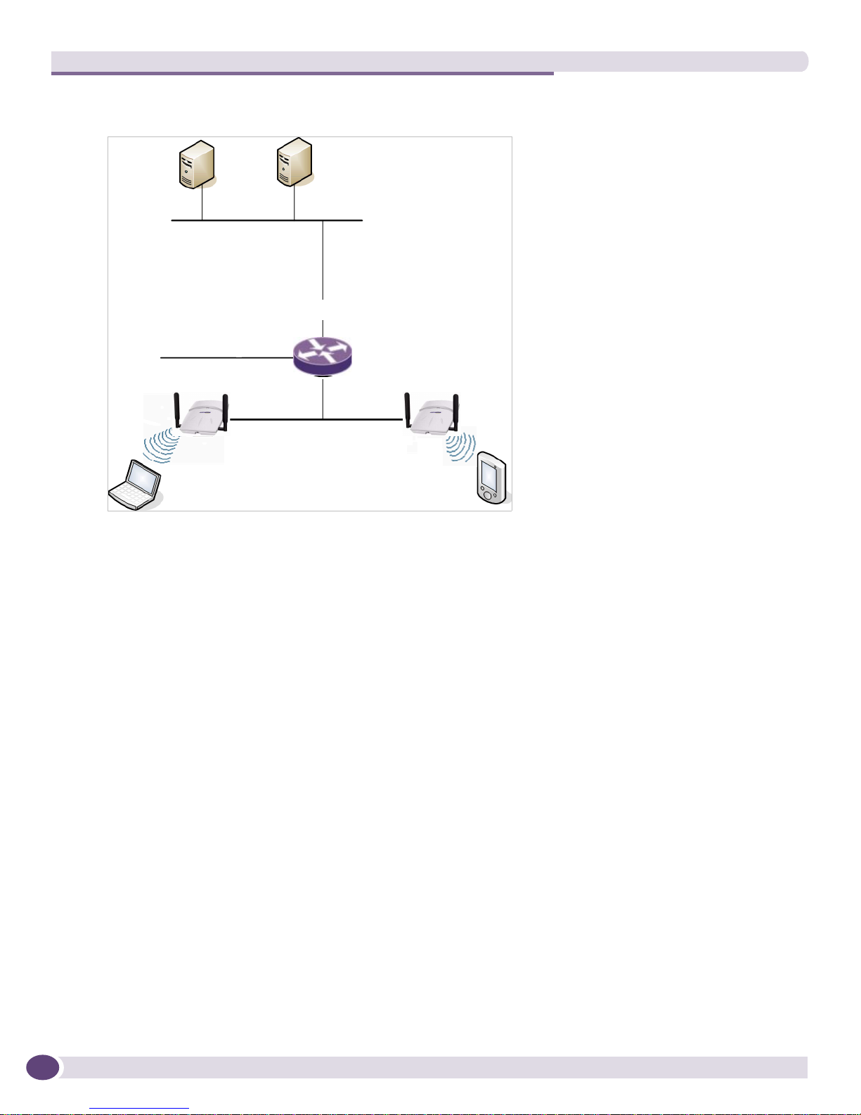
Figure 1: Standard Wireless Network Solution Example
RADIUS
DHCP
Server
Authentication
Server
Router
Wireless AP
Wireless Device
Wireless AP
Wireless Device
The wireless devices and the wired networks communicate with each other using standard networking
protocols and addressing schemes. Most commonly, Internet Protocol (IP) addressing is used.
Elements of the Summit WM Controller, Access Points
and Software Solution
The Summit WM Controller, Access Points and Software solution consists of two devices:
● Summit WM Controller
● Wireless APs
This architecture allows a single Summit WM Controller to control many Wireless APs, making the
administration and management of large networks much easier.
There can be several Summit WM Controllers in the network, each with a set of registered Wireless
APs. The Summit WM Controllers can also act as backups to each other, providing stable network
availability.
In addition to the Summit WM Controllers and Wireless APs, the solution requires three other
components, all of which are standard for enterprise and service provider networks:
● RADIUS Server (Remote Access Dial-In User Service) or other authentication server
● DHCP Server (Dynamic Host Configuration Protocol)
● SLP (Service Location Protocol)
Summit WM20 User Guide, Software Release 4.222
Elements of the Summit WM Controller, Access Points and Software Solution
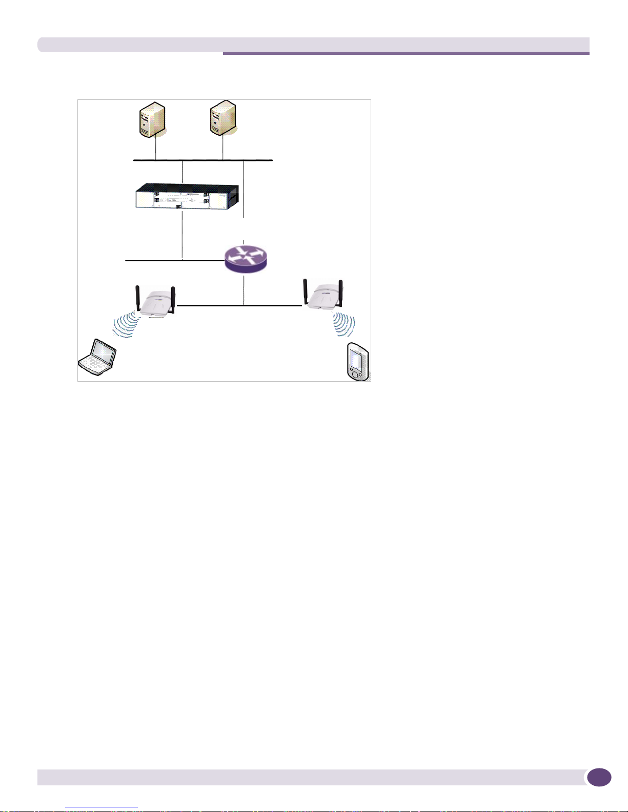
Figure 2: Extreme Networks Solution
DHCP
Server
RADIUS Server
Summit WM
Controller
Router
Wireless AP
Wireless AP
Wireless Device
Wireless Device
As illustrated in Figure 2, the Summit WM Controller appears to the existing network as if it were an
access point, but in fact one Summit WM Controller controls many Wireless APs. The Summit WM
Controller has built-in capabilities to recognize and manage the Wireless APs. The Summit WM
Controller:
● Activates the Wireless APs
● Enables Wireless APs to receive wireless traffic from wireless devices
● Processes the data traffic from the Wireless APs
● Forwards or routes the processed data traffic out to the network
● Authenticates requests and applies access policies
Simplifying the Wireless APs makes them cost-effective, easy to manage, and easy to deploy. Putting
control on an intelligent centralized Summit WM Controller enables:
● Centralized configuration, management, reporting, and maintenance
● High security
● Flexibility to suit enterprise
● Scalable and resilient deployments with a few Summit WM Controllers controlling hundreds of
Wireless APs
The Summit WM Controller, Access Points and Software system:
● Scales up to Enterprise capacity – One Summit WM20 Controller controls as many as 32 Wireless
APs. In turn each Wireless AP can handle up to 254 wireless devices, with each radio supporting a
maximum of 128. With additional Summit WM Controllers, the number of wireless devices the
solution can support can reach into the thousands.
Summit WM20 User Guide, Software Release 4.2 23

Overview of the Summit WM Controller, Access Points and Software Solution
● Integrates with existing network – A Summit WM Controller can be added to an existing enterprise
network as a new network device, greatly enhancing its capability without interfering with existing
functionality. Integration of the Summit WM Controllers and Wireless APs does not require any
reconfiguration of the existing infrastructure (for example, VLANs).
● Offers centralized management and control – An administrator accesses the Summit WM Controller
in its centralized location to monitor and administer the entire wireless network. From the Summit
WM Controller, the administrator can recognize, configure, and manage the Wireless APs and
distribute new software releases.
● Provides easy deployment of Wireless APs – The initial configuration of the Wireless APs on the
centralized Summit WM Controller can be done with an automatic “discovery” technique. For more
information, see “Discovery and Registration Overview” on page 56.
● Provides security via user authentication – Uses existing authentication (AAA) servers to
authenticate and authorize users.
● Provides security via filters and privileges – Uses virtual networking techniques to create separate
virtual networks with defined authentication and billing services, access policies, and privileges.
● Supports seamless mobility and roaming – Supports seamless roaming of a wireless device from
one Wireless AP to another on the same Summit WM Controller.
● Integrates third-party access points – Uses a combination of network routing and authentication
techniques.
● Prevents rogue devices – Unauthorized access points are detected and identified as harmless or
dangerous rogue APs.
● Provides accounting services – Logs wireless user sessions, user group activity, and other activity
reporting, enabling the generation of consolidated billing records.
● Offers troubleshooting capability – Logs system and session activity and provides reports to aid in
troubleshooting analysis.
● Offers Dynamic Radio Management – Automatically selects channels and adjusts Radio Frequency
(RF) signal propagation and power levels without user intervention.
Summit WM Controller, Access Points and Software
and Your Network
This section is a summary of the components of the Summit WM Controller, Access Points and
Software solution on your enterprise network. The following are described in detail in this guide, unless
otherwise stated:
● Summit WM Controller – A rack-mountable network device that provides centralized control over
all access points (both Wireless APs and third-party access points) and manages the network
assignment of wireless device clients associating through access points.
● Wireless AP – A wireless LAN fit access point (IEEE 802.11) that communicates only with a Summit
WM Controller. .
● RADIUS Server (Remote Access Dial-In User Service) (RFC2865), or other authentication server –
An authentication server that assigns and manages ID and Password protection throughout the
network. Used for authentication of the wireless users in either 802.1x or Captive Portal security
modes. The RADIUS Server system can be set up for certain standard attributes, such as filter ID,
and for the Vendor Specific Attributes (VSAs). In addition, Radius Disconnect (RFC3576) which
permits dynamic adjustment of user policy (user disconnect) is supported.
Summit WM20 User Guide, Software Release 4.224

Summit WM Controller, Access Points and Software and Your Network
● DHCP Server (Dynamic Host Configuration Protocol) (RFC2131) – A server that assigns IP
addresses, gateways, and subnet masks dynamically. IP address assignment for clients can be done
by the DHCP server internal to the Summit WM Controller, or by existing servers using DHCP
relay. It is also used by the Wireless APs to discover the location of the Summit WM Controller
during the initial registration process. For SLP, DHCP should have Option 78 enabled. Option 78
specifies the location of one or more SLP Directory Agents.
● Service Location Protocol (SLP) (SLP RFC2608) – Client applications are User Agents and services
that are advertised by a Service Agent. In larger installations, a Directory Agent collects information
from Service Agents and creates a central repository. The Extreme Networks solution relies on
registering “extreme” as an SLP Service Agent.
● Domain Name Server (DNS) – A server used as an alternate mechanism (if present on the
enterprise network) for the automatic discovery process. The Summit WM Controller, Access Points
and Software relies on the DNS for Layer 3 deployments and for static configuration of Wireless
APs. The Summit WM Controller can be registered in DNS, to provide DNS assisted AP discovery.
● Web Authentication Server – A server that can be used for external Captive Portal and external
authentication. The Summit WM Controller has an internal Captive portal presentation page, which
allows Web authentication (Web redirection) to take place without the need for an external Captive
Portal server.
● RADIUS Accounting Server (Remote Access Dial-In User Service) (RFC2866) – A server that is
required if RADIUS Accounting is enabled.
● Simple Network Management Protocol (SNMP) – A Manager Server that is required if forwarding
SNMP messages is enabled.
● Check Point Server (Check Point Event Logging API) – A server for security event logging that is
required if a firewall application is enabled. Checkpoint ELA certification for OPSEC is provided.
● Network infrastructure – The Ethernet switches and routers must be configured to allow routing
between the various services noted above. Routing must also be enabled between multiple Summit
WM Controllers for the following features to operate successfully:
● Availability
● Mobility
● Summit WM series Spy for detection of rogue access points
Some features also require the definition of static routes.
● Web browser – A browser provides access to the Summit WM Controller Management user
interface to configure the Summit WM Controller, Access Points and Software.
● SSH Enabled Device – A device that supports Secure Shell (SSH) is used for remote (IP) shell access
to the system.
● Zone Integrity – The Zone integrity server enhances network security by ensuring clients accessing
your network are compliant with your security policies before gaining access. Zone Integrity Release
5 is supported.
Network Traffic Flow
Figure 3 illustrates a simple configuration with a single Summit WM Controller and two Wireless APs,
each supporting a wireless device. A RADIUS server on the network provides authentication, and a
DHCP server is used by the Wireless APs to discover the location of the Summit WM Controller during
the initial registration process. Network inter-connectivity is provided by the infrastructure routing and
switching devices.
Summit WM20 User Guide, Software Release 4.2 25
Overview of the Summit WM Controller, Access Points and Software Solution
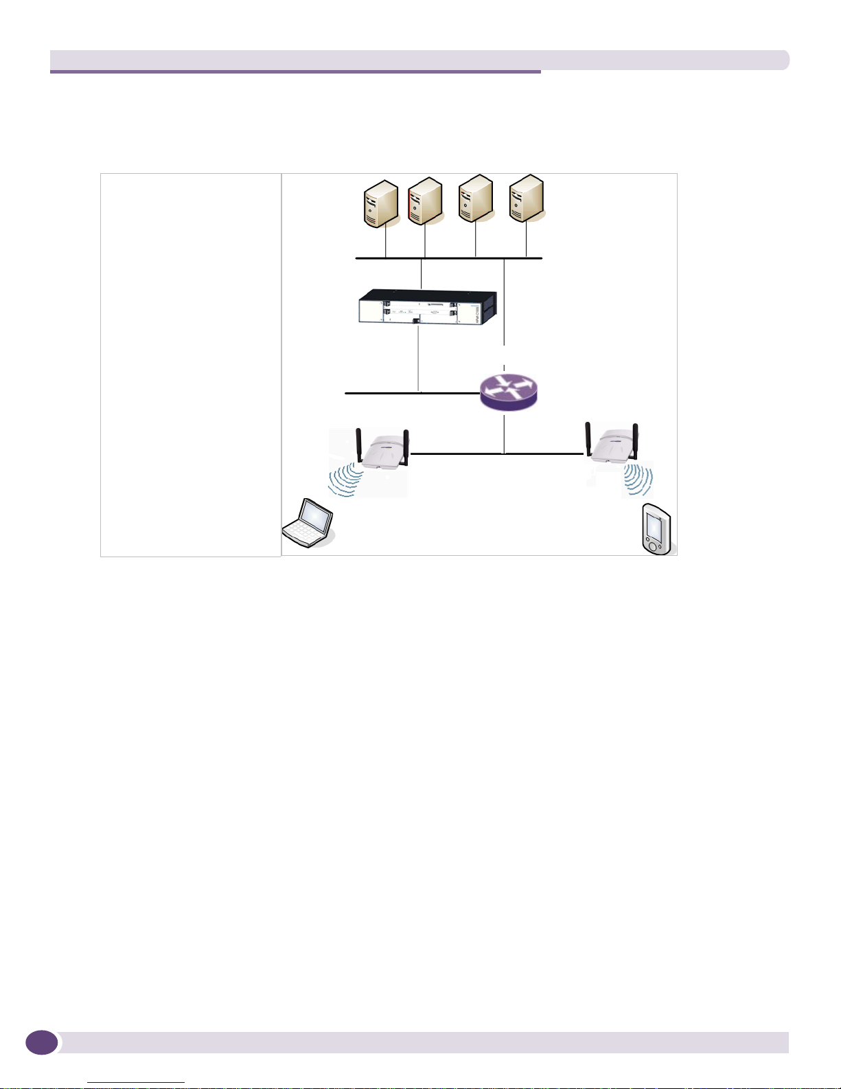
Figure 3: Traffic Flow Diagram
Packet Transmission
Control and Routing
• WM Authenticates wireless
user
Tunneling
• AP sends data traffic to WM
through UDP tunnel called
CTP
• Using WASSP tunnels, WM
allows wireless clients to
roam to Wireless APs on
different WMs
802.11 Packet Transmission
• 802.11 beacon and probe,
wireless device associates
with a Wireless AP by its
SSID
DHCP
Server
Summit WM
Controller
Wireless AP
Wireless Device
RADIUS
Server
External
CP Server
Router
External Web
Authentication
Server
Wireless AP
Wireless Device
Each wireless device sends IP packets in the 802.11 standard to the Wireless AP. The Wireless AP uses a
UDP (User Datagram Protocol) based tunnelling protocol to encapsulate the packets and forward them
to the Summit WM Controller. In a typical configuration, access points can be configured to locally
bridge traffic (to a configured VLAN) directly at their network point of attachment. The Summit WM
Controller decapsulates the packets and routes these to destinations on the network.
The Summit WM Controller functions like a standard router, except that it is configured to route only
network traffic associated with wireless connected users. The Summit WM Controller can also be
configured to simply forward traffic to a default or static route if dynamic routing is not preferred.
Network Security
The Summit WM Controller, Access Points and Software system provides features and functionality to
control network access. These are based on standard wireless network security practices.
Current wireless network security methods provide protection. These methods include:
● Shared Key authentication that relies on Wired Equivalent Privacy (WEP) keys
● Open System that relies on Service Set Identifiers (SSIDs)
● 802.1x that is compliant with Wi-Fi Protected Access (WPA)
● Captive Portal based on Secure Sockets Layer (SSL) protocol
Summit WM20 User Guide, Software Release 4.226

Summit WM Controller, Access Points and Software and Your Network
The Summit WM Controller, Access Points and Software system provides the centralized mechanism by
which the corresponding security parameters are configured for a group of APs.
● Wired Equivalent Privacy (WEP) is a security protocol for wireless local area networks defined in the
802.11b standard
● Wi-Fi Protected Access version 1 (WPA1™) with Temporal Key Integrity Protocol (TKIP)
● Wi-Fi Protected Access version 2 (WPA2™) with Advanced Encryption Standard (AES) and Counter
Mode with Cipher Block Chaining Message Authentication Code (CCMP)
Authentication
The Summit WM Controller relies on a RADIUS server, or authentication server, on the enterprise
network to provide the authentication information (whether the user is to be allowed or denied access
to the network). A RADIUS client is implemented to interact with infrastructure RADIUS servers.
The Summit WM Controller provides authentication using:
● Captive Portal – a browser-based mechanism that forces users to a Web page
● RADIUS (using IEEE 802.1x)
The 802.1x mechanism is a standard for authentication developed within the 802.11 standard. This
mechanism is implemented at the wireless Port, blocking all data traffic between the wireless device
and the network until authentication is complete. Authentication by 802.1x standard uses Extensible
Authentication Protocol (EAP) for the message exchange between the Summit WM Controller and the
RADIUS server.
When 802.1x is used for authentication, the Summit WM Controller provides the capability to
dynamically assign per-wireless-device WEP keys (called per-station WEP keys in 802.11). Or in the case
of WPA, the Summit WM Controller is not involved in key assignment. Instead, the controller is
involved in the path between RADIUS server and the user to negotiate the appropriate set of keys. With
WPA2 the material exchange produces a Pairwise Master Key which is used by the AP and the user to
derive their temporal keys. (The keys change over time.)
In the Summit WM Controller, Access Points and Software, a RADIUS redundancy feature is provided,
where you can define a failover RADIUS server (up to 2 servers) in the event that the active RADIUS
server fails.
Privacy
Privacy is a mechanism that protects data over wireless and wired networks, usually by encryption
techniques.
The Summit WM Controller, Access Points and Software supports the Wired Equivalent Privacy (WEP)
standard common to conventional access points.
It also provides Wi-Fi Protected Access version 1 (WPA v.1) encryption, based on Pairwise Master Key
(PMK) and Temporal Key Integrity Protocol (TKIP). The most secure encryption mechanism is WPA
version 2, using Advanced Encryption Standard (AES).
Summit WM20 User Guide, Software Release 4.2 27

Overview of the Summit WM Controller, Access Points and Software Solution
WM Access Domain Services
WM Access Domain Services (WM-AD) provide a versatile method of mapping wireless networks to
the topology of an existing wired network.
When you set up WM-AD on the Summit WM Controller you are defining subnets for groups of
wireless users. The WM-AD definition provides the binding between WM-AD IP topology
configuration (Routing, DHCP policy) and the RF configuration parameters that advertise and control
network access (SSID, Privacy policy: WEP and WPA). This technique enables policies and
authentication to be applied to the groups of wireless users on a WM-AD, as well as the collecting of
accounting information on user sessions that can be used for billing.
When a WM-AD is set up on the Summit WM Controller:
● One or more Wireless APs (by radio) are associated with it
● A range of IP addresses is set aside for the Summit WM Controller’s DHCP server to assign to
wireless devices
If routing protocol is enabled, the Summit WM Controller advertises the WM-AD as a routable network
segment to the wired network and routes traffic between the wireless devices and the wired network.
The Summit WM Controller WM20 also supports VLAN-bridged assignment for WM-ADs. This allows
the controller to directly bridge the set of wireless devices associated with a WM-AD directly to a
specified core VLAN. The following lists how many WM-ADs the Summit WM20 Controller can
support:
● WM20 – Up to 8 WM-ADs
The Wireless AP radios can be assigned to each of the configured WM-ADs in a system. Each AP can be
the subject of 8 WM-AD assignments (corresponding to the number of SSIDs it can support). Once a
radio has all 8 slots assigned, it is no longer eligible for further assignment.
Static Routing and Routing Protocols
Routing can be used on the Summit WM Controller to support the WM-AD definitions. Through the
user interface you can configure routing on the Summit WM Controller to use one of the following
routing techniques:
● Static routes – Use static routes to set the default route of a Summit WM Controller so that
legitimate wireless device traffic can be forwarded to the default gateway.
● Open Shortest Path First (OSPF, version 2) (RFC2328) – Use OSPF to allow the Summit WM
Controller to participate in dynamic route selection. OSPF is a protocol designed for medium and
large IP networks with the ability to segment routes into different areas by routing information
summarization and propagation. Static Route definition and OSPF dynamic learning can be
combined, but a static route definition will take precedence over dynamic rules.
● Next-hop routing – Use next-hop routing to specify a unique gateway to which traffic on a WM-AD
is forwarded. Defining a next-hop for a WM-AD forces all the traffic in the WM-AD to be forwarded
to the indicated network device, bypassing any routing definitions of the controller's route table.
Summit WM20 User Guide, Software Release 4.228

Summit WM Controller, Access Points and Software and Your Network
Packet Filtering Policy
Policy refers to the rules that allow different groups of users access to the network. The Summit WM
Controller, Access Points and Software system can link authorized users to user groups. These user
groups then can be confined to predefined portions of the network.
In the Summit WM Controller, Access Points and Software system, network access policy is carried out
by means of packet filtering within a WM-AD.
In the Summit WM Controller user interface, you set up a packet filtering policy by defining a set of
hierarchical rules that allow or deny traffic to specific IP addresses, IP address ranges, or service ports.
The sequence and hierarchy of these filtering rules must be carefully designed based on your enterprise
user access plan.
The authentication technique selected determines how filtering is carried out:
● If authentication is by SSID and Captive Portal, a non-authenticated filter allows all users to get as
far as the Captive Portal Web page, where logon authentication occurs. When authentication is
returned, then filters are applied, based on user ID and permissions.
● If authentication is by AAA (802.1x), users have logged on and have been authenticated before being
assigned an IP address. When authentication is completed, the authenticated filter is assigned by
default unless a more user-specific filter is returned or indicated by the authentication mechanism.
The characteristics and level of access for a filter are controlled and defined by the system
administrator.
Mobility and Roaming
In typical configurations that are not Summit WM, APs are setup as bridges that bridge wireless traffic
to the local subnet. In bridging configurations, the user obtains an IP address from the same subnet as
the AP. If the user roams within APs on the same subnet, it is able to keep using the same IP address.
However, if the user roams to another AP outside of that subnet, its IP address is no longer valid. The
user's client device must recognize that the IP address it has is no longer valid and re-negotiate a new
one on the new subnet. The protocol does not mandate any action on the user. The recovery procedure
is entirely client dependent. Some clients automatically attempt to obtain a new address on roam (which
affects roaming latency), while others will hold on to their IP address. This loss of IP address continuity
seriously affects the client's experience in the network, because in some cases it can take minutes for a
new address to be negotiated.
The Summit WM Controller, Access Points and Software solution centralizes the user's network point of
presence, therefore abstracting and decoupling the user's IP address assignment from that of the APs
location subnet. That means that the user is able to roam across any AP without loosing its own IP
address, regardless of the subnet on which the serving APs are deployed.
Network Availability
The Summit WM Controller, Access Points and Software provides availability against Wireless AP
outages, Summit WM Controller outages, and even network outages. The Summit WM Controller in a
VLAN bridged WM-AD can potentially allow the user to retain the IP address in a failover scenario, if
the WM-AD/VLAN is common to both controllers. For example, availability is provided by defining a
paired controller configuration by which each peer can act as the backup controller for the other's APs.
APs in one controller are allowed to failover and register with the alternate controller.
Summit WM20 User Guide, Software Release 4.2 29

Overview of the Summit WM Controller, Access Points and Software Solution
If a Summit WM Controller fails, all of its associated Wireless APs can automatically switch over to
another Summit WM Controller that has been defined as the secondary or backup Summit WM
Controller. If the AP reboots, the original Summit WM Controller is restored. The original Summit WM
Controller is restored if it is active. However, active APs will continue to be attached to the failover
controller until the administrator releases them back to the original home controller.
Quality of Service (QoS)
The Summit WM Controller, Access Points and Software provides advanced Quality of Service (QoS)
management to provide better network traffic flow. Such techniques include:
● WMM (Wi-Fi Multimedia) – WMM is enabled per WM-AD. The Summit WM Controller provides
centralized management of these AP features. For devices with WMM enabled, the standard
provides multimedia enhancements for audio, video, and voice applications. WMM shortens the
time between transmitting packets for higher priority traffic. WMM is part of the 802.11e standard
for QoS.
● IP ToS (Type of Service) or DSCP (Diffserv Codepoint) – The ToS/DSCP field in the IP header of a
frame indicates the priority and QoS for each frame. The IP TOS and/or DSCP is maintained within
CTP (CAPWAP Tunneling Protocol) by copying the user IP QoS information to the CTP header—this
is referred to as Adaptive QoS.
Quality of Service (QoS) management is also provided by:
● Assigning high priority to an SSID (configurable)
● Adaptive QoS (automatic)
● Support for legacy devices that use SpectraLink Voice Protocol (SVP) for prioritizing voice traffic
(configurable)
System Configuration Overview
To set up and configure the Summit WM Controller and Wireless APs, follow these steps:
1 First-time Setup – Perform “First-Time Setup” of the Summit WM Controller on the physical
network to modify the Management Port IP address for the enterprise network.
2 Product Key – Apply a Product Key file, for licensing purposes. If no Product Key is enabled, the
Summit WM Controller functions with some features enabled in demonstration mode. Not all
features are enabled in this mode.
3 Data Port Setup – Set up the Summit WM Controller on the network by configuring the physical
data ports and their function as “host port”, “router port”, or “3rd party AP port”.
4 Routing Setup – Configure static routes and OSPF parameters for any port defined as a router port,
if appropriate to the network.
5 Wireless AP Initial Setup – Connect the Wireless APs to the Summit WM Controller. They will
automatically begin the Discovery of the Summit WM Controller, based on factors that include:
● Their Registration mode (in the Wireless AP Registration screen)
● The enterprise network services that will support the discovery process
The default AP configuration allows for a definition of a default configuration template, whereby
APs automatically receive complete configuration. For typical deployments where all APs are to all
Summit WM20 User Guide, Software Release 4.230
 Loading...