

Page 1
virtchas.book Page i Friday, May 29, 1998 10:08 AM
Summit Virtual Chassis
Design and Installation
Guide
Extreme Networks, Inc.
10460 Bandley Drive
Cupertino, California 95014
(888) 257-3000
http://www.extremenetworks.com
Published: June 1998
Part No: 120031-00 rev. 01
Page 2
virtchas.book Page ii Friday, May 29, 1998 10:08 AM
Copyright © Extreme Networks, Inc., 1998. All rights reserved. No part of this documentation may be
reproduced in any form or by any means or used to make any derivative work (such as translation,
transformation, or adaptation) without permission from Extreme Networks, Inc.
Extreme Networks, ExtremeWare, Summit, SummitLink,Virtual C hassis and the Extreme Networks
logo are trademarks of Extreme Networks.
All other brand and product names are registered trademarks or trademarks of their respective
holders.
ii
Page 3
virtchas.book Page 1 Friday, May 29, 1998 10:08 AM
Summit Vir tual Chassis Design
and Installation Guide
The Summit™ Vi rtual Chassis™ is a high-performance, low-cost external backplane that
connects up to eight stacked or distributed Summit switches into one cohesive system.
™
The Summit Virtual Chassis comes with eight SummitLin k
UMMARY OF FEATURES
S
Features of the Summit Virtual Chassis include the following:
• Increased port density
• Policy-based Quality of Service (QoS)
• Load-sharing links
• Extensive fault-tolerant capabilities
— Redundant power supplies
— Hot-swappable switches
• Hot-swappable Virtual Chassis
— Environmental senso rs
backplane channels.
UMMIT VIRTUAL CHASSIS DESIGN AND INSTALLATION GUIDE
S
1
Page 4
virtchas.book Page 2 Friday, May 29, 1998 10:08 AM
UMMARY OF FEATURES
S
NCREASED PORT DENSITY
I
The Summit Virtual Chassis can be combined with any member of the Summit switch
family. When four Summit Virtual Chassis are used with eight Summit1 switches, up to
32 Gigabit Ethernet ports can be connected using the Virtual Chassis external backplane.
When two Virtual Chassis are combined with eight Summit48 switche s, up to 384
10/100 Mbps Ethernet ports can be connected. A single Virtual Chassis connected to
eight Summit3 switches provides 192 10/100 Mbps ports.
OLICY-BASED QUALITY OF SERVICE
P
(QOS)
Policy-based QoS is a feature of the Sum mit switch family. QoS profiles are defined in
the Summit switch, and allow you to specify priority, and minimum and maximum
bandwidth per traffic group. You can define QoS traffic groups based on the following:
• Internet Protocol (IP) destination address
• Virtual LAN (VLAN) (including IP subnet or protocol)
• Media Access Control (MAC) destination address
• Physical source port
• 802.1p prioritization
™
ExtremeWare
software running on the Sum mit switch maps the QoS p rofiles into
queues on each port of the switch. When up to eight Summit switches are connected to
a Summit Virtual Chassis, four interconnecting queues for each switch ( totaling 32
queues) are allocated on each Summit Virtual Chassis link.
OAD-SHARING LINKS
L
For increased fault tolerance, throughput, and bandwidth, two- or 4four-port
load-sharing links can be used to create parallel path s between Summit switches and
two or four Summit Virtual Chassis.
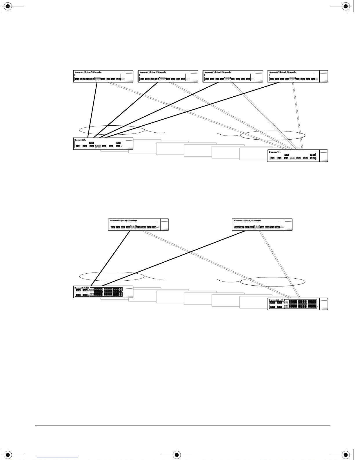
Figure 1 shows two Summit1 switches connected using four parallel paths to four
Summit Virtual Chassis. The result is a full mesh of parallel paths between each Summit
switch and the Summit Virtual Chassis.
2 S
UMMIT VIRTUAL CHASSIS DESIGN AND INSTALLATION GUIDE
Page 5
virtchas.book Page 3 Friday, May 29, 1998 10:08 AM
Switch #1
4-port
load-sharing groups
UMMARY OF FEATURES
S
Switch #8
Figure 1:
Four-port load-sha ring links with t he Summit Vir tual Chassis
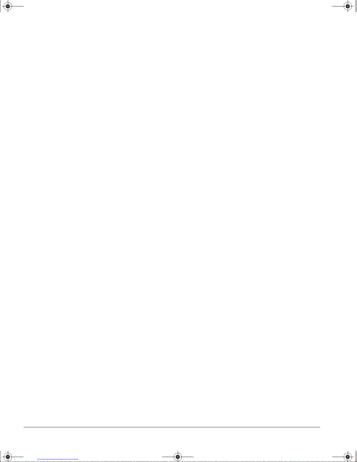
Figure 2 shows two Summ it48 switches using two parallel paths to tw o Summit Virtual
Chassis. The result is a full mesh of parallel paths.
2-port
load-sharing groups
Switch #1
Switch #8
Figure 2:
Two-por t load-shar ing links with the Summit Virtual Chassis
Using load-sharing lin ks, the Summ it Virtual Chassis distributes traffic to and from each
Summit switch on any of the pa rallel connected paths. This results in faster data
throughput among the switches conn ected to the Summit Virtual Chassis.
UMMIT VIRTUAL CHASSIS DESIGN AND INSTALLATION GUIDE
S
3
Page 6
virtchas.book Page 4 Friday, May 29, 1998 10:08 AM
UMMARY OF FEATURES
S
Another advantage of parallel paths between Summit switches and the Summit Virtual
Chassis is that the a llocati on of tra ffic between connec tions is transpa rent to the ad dress
tables and routing protocols. If a connection is broken, traffic is redirected to a parallel
path without causing an address table or routing table update.
XTENSIVE FAULT TOLERANT CAPABILITIES
E
The Summit Virtual Chassis includes a number of fault tolerant capabilities, in cluding
the following:
— Redundant power supplies
— Hot-swappable switches
— Hot-swappable Virtual Chassis
— Environmental senso rs
R
EDUNDANT POWER SUPPLIES
The Summit Vi rtual Chassis is equipped with two internal load-sharing power supplies.
A single power supply provides power to the Summit Virtual Chassis. Combined, the
two power supplies provide load-balancing to increase the longevity of each supply,
and deliver uninterrupted service in the event of a failure.
In addition to the two internal power supplies, the Summit Virtual Chassis comes with
dual external redundant power supplies (RPS) that deliver power for up to two Summit
switches in the stack. DC cables are provided to connect each RPS output to a single
Summit switch.
The Summit Virtual Chassis has two power sockets. The upper power socket provides
power to one of the Summit Virtual Chassis internal power supplies. It also provides
backup power to the Summit swi tch that is connected to th e Summit Virtual Chassis
using the upper RPS port.
The lower power socket provides power to the second Summit Vi rtual Chassis internal
power supply, and to the Summit switch that i s connected to the Summit Virtual
Chassis using the lower RPS port .
4 S
UMMIT VIRTUAL CHASSIS DESIGN AND INSTALLATION GUIDE
Page 7

virtchas.book Page 5 Friday, May 29, 1998 10:08 AM
UMMIT VIRTUAL CHASSIS FRONT VIEW
S
HOT-S
WAPPING SUMMIT SWITCHES AND SUMMIT VIRTUAL CHASSIS UNITS
You can easily add, remove, and replace Summit switches that are interconnected with
the Summit Virtual Chassis without affecting users li nked to other swi tches in the s tack.
No actions are required prior to disconnecting a Summi t switch, removing it from the
stack, adding a new swit ch to the stack, or replacing a switch . Other switches connected
to Summit Virtual Chassis continue to operate normally. When a s witch is replaced or
added, users connected to the new switch can automatically communicate with devices
attached to other switches in the stack.
When a stack of Summ it swi tches are connected t o two or more Summit Virtual Chassis,
you can hot-swap one of t he Virtua l Chassis without affecting commu nication between
devices attached to the stack. If a system LED on a Summit Virtual Chassis indicates a
failure, the Summit Virtual Chassis can be disconnected, removed from the stack and
replaced, while remaining transparent to all users. All traffic continue s to pass through
the operational Summ it Virtual Chassis while the failed unit is replaced.
E
NVIRONMENTAL SENSORS
The Summit Vi rtual Chassis is equipped with sensors that monitor the internal
temperature and send an alert if the temperature exceeds 60 degrees centigrade.
Fans in the Summit Virtual Chassis are built with a tachometer sensor th at detects a fan
failure if the rotation speed decreases by 20%. This allows you to ma ke necessary
repairs to the Summit Virtual Chassis before a failure occurs.
UMMIT VIRTUAL
S
Figure 3 shows the front panel view of the Su mmit Virtual Chassis.
SummitLink ports
Figure 3:
UMMIT VIRTUAL CHASSIS DESIGN AND INSTALLATION GUIDE
S
Summit Vir tual Chassis fron t panel
HASSIS FRONT VIEW
C
AMBER
TX ACTIVITY
AMBER
RX ACTIVITY
GREEN
LINK OK
AMBER
LINK ERROR
TX RX
ACTIVITY
12345678
12345678
12345678
LINK
Port status
LEDs
SummitLink ports
Unit status LEDs
87654321
5
Page 8
virtchas.book Page 6 Friday, May 29, 1998 10:08 AM
UMMIT VIRTUAL CHASSIS FRONT VIEW
S
ORTS
P
The Summit Virtual Chassis has eight SummitLink po rts. All the ports use SC
connectors and support the same media and distances as 1000BASE-SX over
50/125 micron or 62.5/125 micron fiber-optic cable. The maximum cable length between
a Summit switch and the Sum mit Virtual Chassis is 260 meters. SummitLink ports are
designed for connecting the Summit Virtual Chassis only to a Su mmit switch.
SummitLink ports do not support connections to any other device type.
S
LED
Table 1 describes the LED behavior on the Su mmit Virtual Chassis.
Ta b l e 1 :
Unit Status
LEDs Color Indicates
PS1 Green
RPS1 Green The first redundant power supply (RPS) of the Summit Virtual
PS2 Green
RPS2 Green The secon d RPS of th e Summit Vi rtual Cha ssis is p owering a
OVER TEMP Off
FAN FAIL Off
Summit Virtual Chassis LEDs
Power supply #1 of the Summit Virtual Chassis is operating.
Off
Off
Yellow
Yellow
The Summit Virtual Chassis is indicating a power supply
failure.
Chassis is powering a S ummit swit ch.
Power supply #2 of the Summit Virtual Chassis is operating.
The Summit Virtual Chassis is indicating a power supply
failure.
Summit switch.
The Summit Virtual Chassis temperature is normal.
The Summit Virtual Chassis is indicating an overheat condition
(>60 degrees Celsius).
The Summit Virtual Chassis fan is operating properly.
The Summit Virtual Chassis fan speed has slowed to 80% or
less of full rotational speed, and should be replaced.
6 S
UMMIT VIRTUAL CHASSIS DESIGN AND INSTALLATION GUIDE
Page 9
virtchas.book Page 7 Friday, May 29, 1998 10:08 AM
UMMIT VIRTUAL CHASSIS REAR VIEW
S
Ta b l e 1 :
Unit Status
LEDs
SummitLink Port Status LEDs
Link Green
TX Activity Yellow
RX Activity Yellow
UMMIT VIRTUAL
S
Summit Virtual Ch assis LEDs (continued)
Color Indicates
Link is present.
Yellow
Off
Off
Off
Link error.
No link, or either the Summ it Virtual Chassis or the Summit
switch at tached to this port is powered off.
Frames are being transmitted on this port.
No transmit activity detected on this port.
Frames are being received on this port.
No receive activity detected on this port.
HASSIS
C
EAR VIEW
R
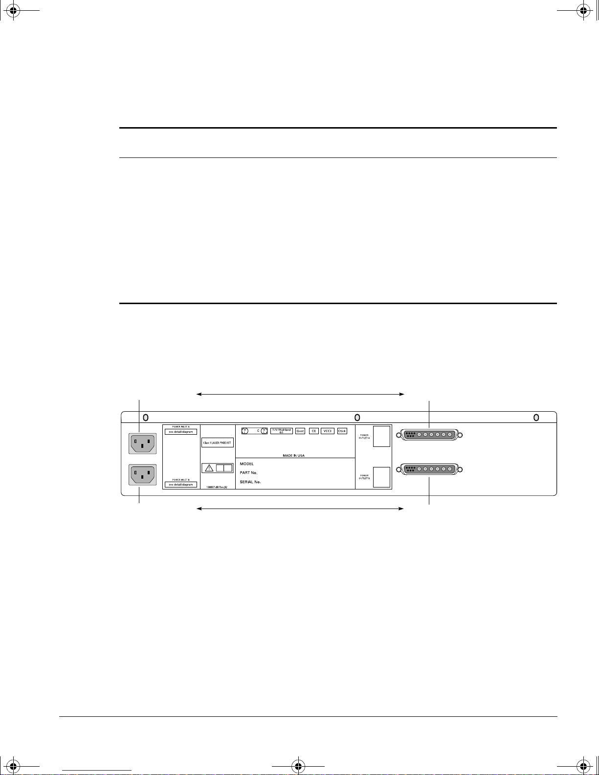
Figure 4 shows the rear panel view of the Sum mit Vi rtual Chassis.
RPS port APower socket A
Figure 4:
OWE R SOCKETS
P
Summit Vir tual Chassis rear pa nel
The Summit Virtual Chassis has two power sockets. The upper power socket provides
power to one of the internal Summit Virtual Chassis power supplies. It also provides
redundant load-shared pow er to the Summit switch connected to the Summit Virtual
Chassis using RP S port A.
UMMIT VIRTUAL CHASSIS DESIGN AND INSTALLATION GUIDE
S
RPS port BPower socket B
7
Page 10
virtchas.book Page 8 Friday, May 29, 1998 10:08 AM
UMMIT VIRTUAL CHASSIS REAR VIEW
S
The lower power socket provides power to the second internal power supply, and to the
Summit switch connected to the Summit Vi rtual Chassis using RPS port B.
The upper power socket powers only the upper RPS por t. The lower power
socket powers only the lower RPS por t.
If you want to distribute the input A C power source across multiple, individual circuit
breakers, you must plug the Summit switch AC power cord into a different circuit
breaker than the circuit breaker to which the Summit Virtual Chassis AC power socket
is connected.
EDUNDANT POWER SUPPLY PORTS
R
The Summit Virtual Chassis has two RPS ports. Each port connects to a different
Summit switch.
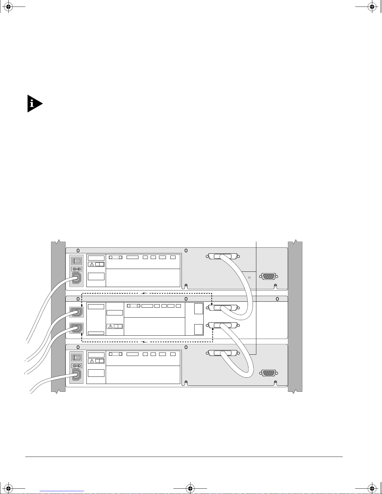
Figure 5 shows the rear view of a rack that has one Summit s witch mounted above the
Summit Virtual Chassis and one Summit switch mounted below. The upper switch i s
cabled to the upper RPS port; the lower switch is cabled to the lower RPS port.
RPS cable (DC)
Figure 5:
8 S
Summit Switches c onnected to a Summit Vir tual Cha ssis
UMMIT VIRTUAL CHASSIS DESIGN AND INSTALLATION GUIDE
Page 11
virtchas.book Page 9 Friday, May 29, 1998 10:08 AM
The upper power socket on the Summit Virtual Chassis provides the AC source for
backup power for the upper switch; the lower power socket provides the AC source for
backup power for the lower switch.
UPPORTED CONFIGURATIONS
S
UPPOR TED
S
ONFIGURATIONS
C
The following two types of Summit Virtual Chassis configurations are supported:
• Single Virtual Chassis stack
• Parallel Virtual Chassis stack (using two or four Summit Virtual Chassis)
A Virtu al Chassis stack is an y valid Virtual Chassis configuration that includes the
Summit Virtual Chassis and Summit switches. A parallel Virtu al Chassis stack can
consist of two or four Summ it Virtual Chassis. Multiple stacks can be combined using
traditional bridging and routing system design elements.
A single Summ it switch can be connected to multiple Summit Vir tual Chas sis
units. However, you can have only one connection between any one Summi t
switch and any one Summit Vir tual Chassis. In add ition, a Summit Vir tual
Chassis cannot conne ct directly to another S ummit Vir tual Chassis.
You cannot use the redundant Gigabi t Ethernet po rt to conne ct to a Summit
Virtual Chassis.
INGLE VIRTUAL CHASSIS STACK
S
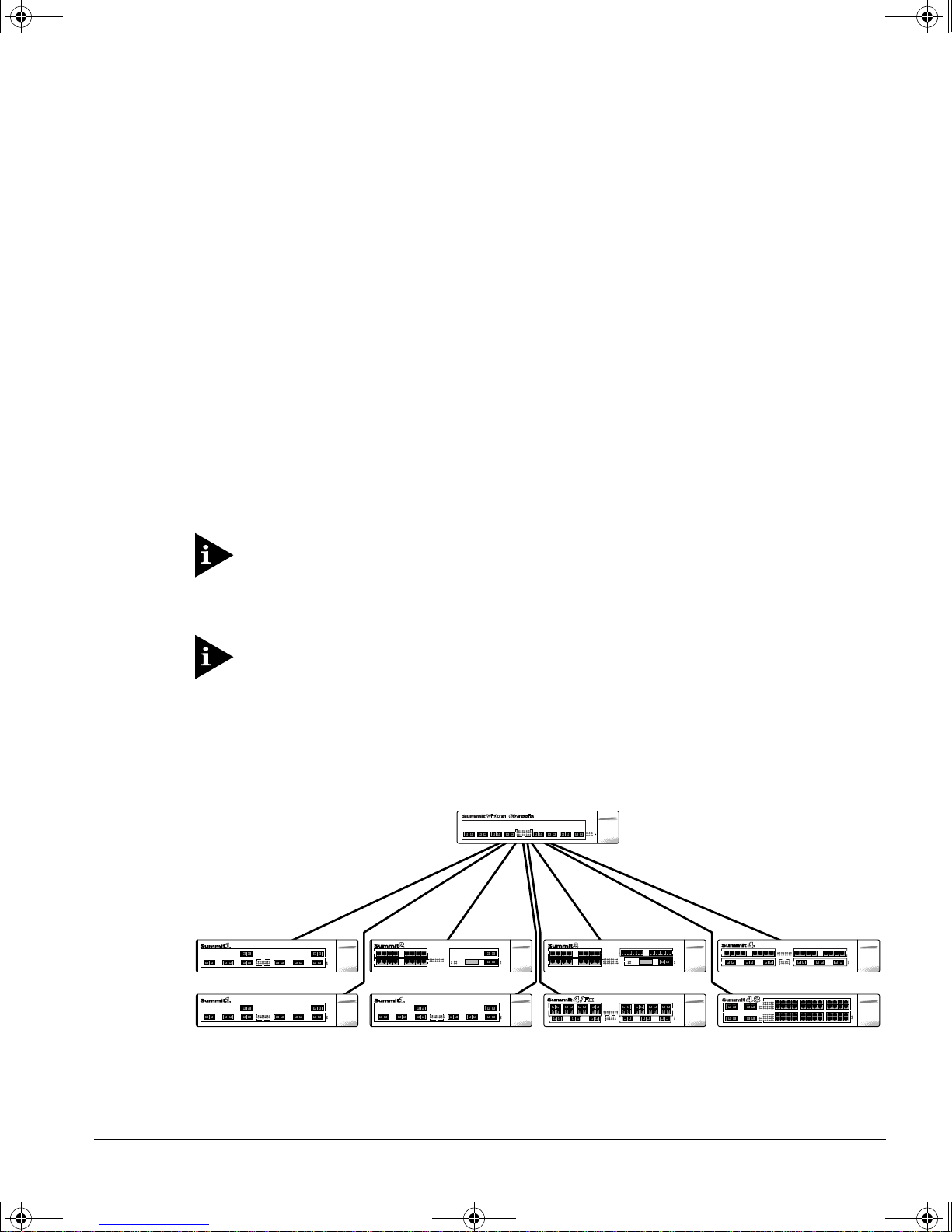
In a single Virtual Chassis stack, one Summit Virtual Chassis can be connected to a
maximum of eight Summit s witches. A single Virtual Chassis stack is shown in Figure 6.
Figure 6:
UMMIT VIRTUAL CHASSIS DESIGN AND INSTALLATION GUIDE
S
Single Vir tual Chassi s stack
9
Page 12
virtchas.book Page 10 Friday, May 29, 1998 10:08 AM
UPPORTED CONFIGURATIONS
S
One Gigabit Ethernet port from each of the Summit switches is cabled to the Summit
Virtual Chass is. The maximum distance between the Summit switch and the Summit
Virtual Chassis is 260 meters. Each Summit switch continues to operate independently.
The Summit Virtual Chassis does not act as an OSI layer 2 bridge hop or an OSI layer 3
router hop. It is transparent to layer 2 and 3 protocols.
It is recommended that you use a single Virtual Chassis stack w hen using the Summit3
switch. A single Virtual Chassis stack can also be us ed with Summit1, Summit2,
Summit4, and Summit48 swi tches.
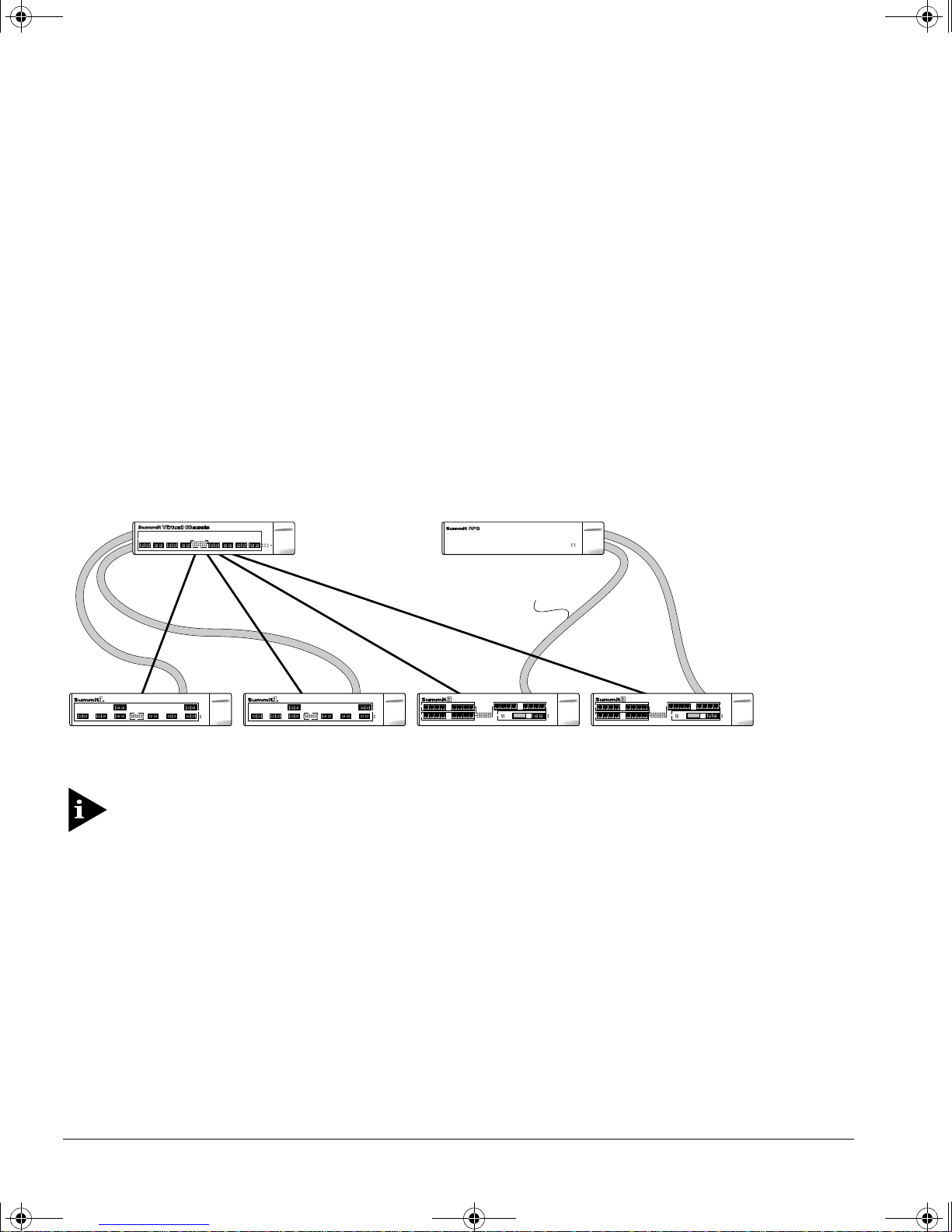
The Summit Virtual Chassis can provide redundant power for two of the Summit
switches shown in Figure 6. Fo r the other Summit switches to h ave backup power, you
must use a Summit RPS. The Summit RPS provides power to up to two Summit
switches. Figure 7 shows the sin gle Virtual Chassis stack with the addition of a Summ it
RPS.
DC RPS cable
Figure 7:
ARALLEL VIRTUAL CHASSIS STACK
P
Single Vir tual Chassis stack with a Summit RPS
For more information on using a S ummit RPS, refer to the
Powe r Supply Installa tion Guide
.
Summit Redundant
The parallel Virtual Chassis stack uses two or four Summ it Virtual Chassis to provide
redundant load-sharing port configurations for up to eight Summit switches. You can
use two Summit Virtual Chassis with Summit2 and Summ it48 switches, and four
Summit Virtual Chassis with Summit1 and Su mmit4 switches.
10 S
UMMIT VIRTUAL CHASSIS DESIGN AND INSTALLATION GUIDE
Page 13
virtchas.book Page 11 Friday, May 29, 1998 10:08 AM
P
ARALLEL VIRTUAL CHASSIS STACK USING TWO SUMMIT VIRTUAL CHASSIS UNITS
A parallel Virtual Chassis stack us ing two Summit Virtual Chassis is used to connect up
to eight Summit2 or Sum mit48 switches.
The Summit2 switch has two Gigabit Ethernet ports, labeled port 17 and port 18. The
Summit48 switch has two Gigabit Ethernet ports, labeled port 49 and p ort 50. For a
parallel Virtual Chassis configuration, port 17 on the Summit2 or port 49 on the
Summit48 is cabled to one of the ports on one of the Summit Virtual Chassis. Port 18 on
the Summit2 or port 50 on the Summit48 is cabled to the second Summit Virtual
Chassis. You must use the same port number on each of the two Summit Virtual
Chassis.
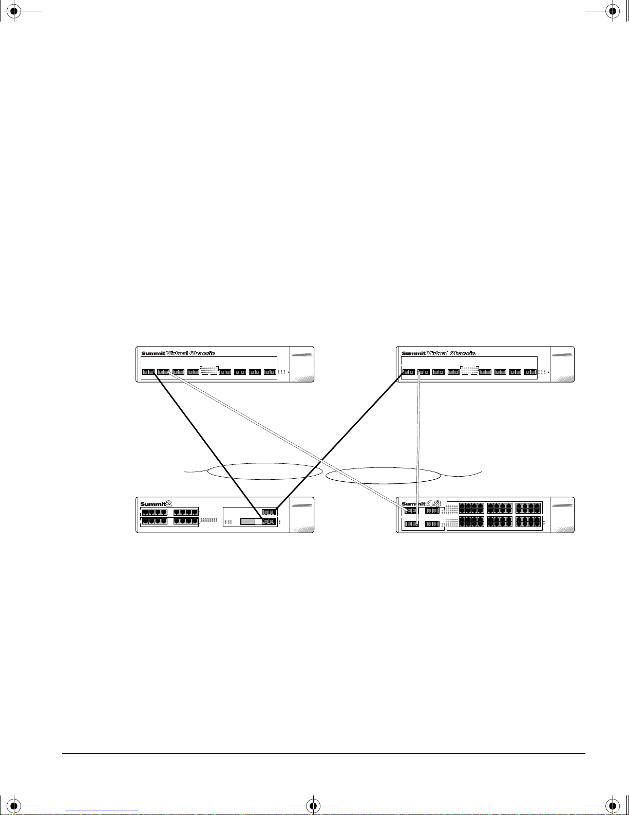
For example, in Figure 8, two Summit2 sw itches, labeled Switch A and Switch B, are
cabled to two Summit Virtual Chassis, labeled Chassis 1 a nd Chassis 2.
UPPORTED CONFIGURATIONS
S
Chassis 1
2-port
load-sharing
group
Switch A
Figure 8:
5 6 7 81 2 3 4
18
17
Parallel Virtual C hassis stack example using Summit2 a nd Summit48
Chassis 2
5 6 7 81 2 3 4
2-port
load-sharing
group
49R49
50R50
Switch B
swit c h es
Switch A is cabled to port 1 on each Summ it Virtual Chassis. Switch B is cabled to port
2 on each Summit Virtual Chassis.
UMMIT VIRTUAL CHASSIS DESIGN AND INSTALLATION GUIDE
S
11
Page 14
virtchas.book Page 12 Friday, May 29, 1998 10:08 AM
UPPORTED CONFIGURATIONS
S
The port connections between the Summit switches and the Summit Virtual Chassis
shown in Figure 8 are as follows:
• Port 17 on Switch A is cabled to port 1 on Chassis 1.
• Port 18 on Switch A is cabled to port 1 on Chassis 2.
• Port 49 on Swit ch B is cabled to port 2 on Chas sis 1.
• Port 50 on Swit ch B is cabled to port 2 on Chas sis 2.
Summit switch connections must be cabled to the same por t numbers on both
Summit Vir tual Chassis. If not, communication among the switches will not
operate properly.
P
ARALLEL STACK USING FOUR SUMMIT VIRTUAL CHASSIS UNITS
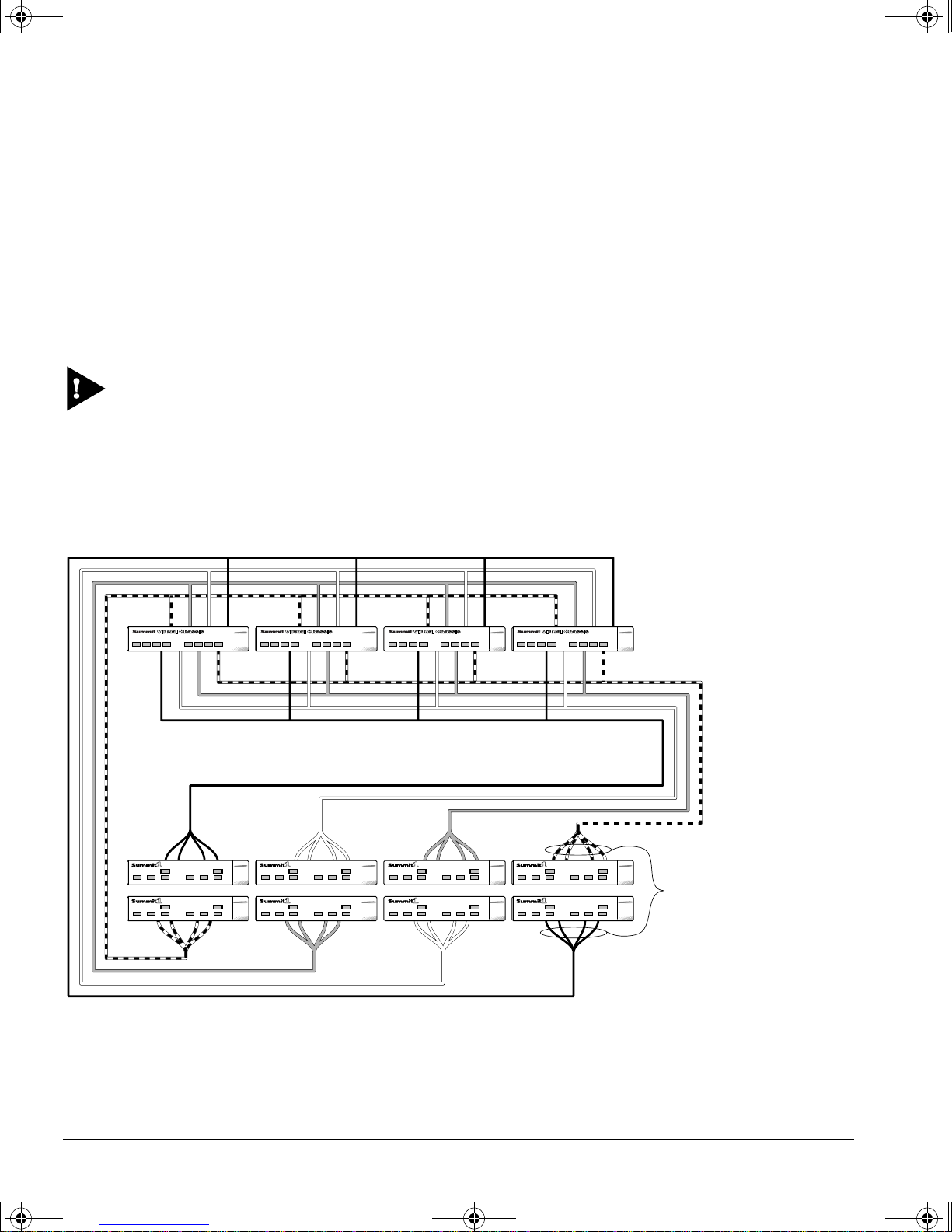
A parallel Virtual Chassis stack using two or four Su mmit Virtual Chassis is used to
connect up to eight Summit1 o r Summit4 switches, as shown in Figure 9.
4-port
load-sharing
groups
Figure 9:
12 S
Four parallel Virt ual Chassis st ack using eight Summit1 or Summit4 switches
UMMIT VIRTUAL CHASSIS DESIGN AND INSTALLATION GUIDE
Page 15
virtchas.book Page 13 Friday, May 29, 1998 10:08 AM
In a parallel Virtual Chassis configuration using S ummit1 or Summ it4 switches, up to
four ports per Summit switch can be cabled to four different Summit Virtual Chassis.
Each switch must be cabled to the same port number on each Summit Virtual Chassis.
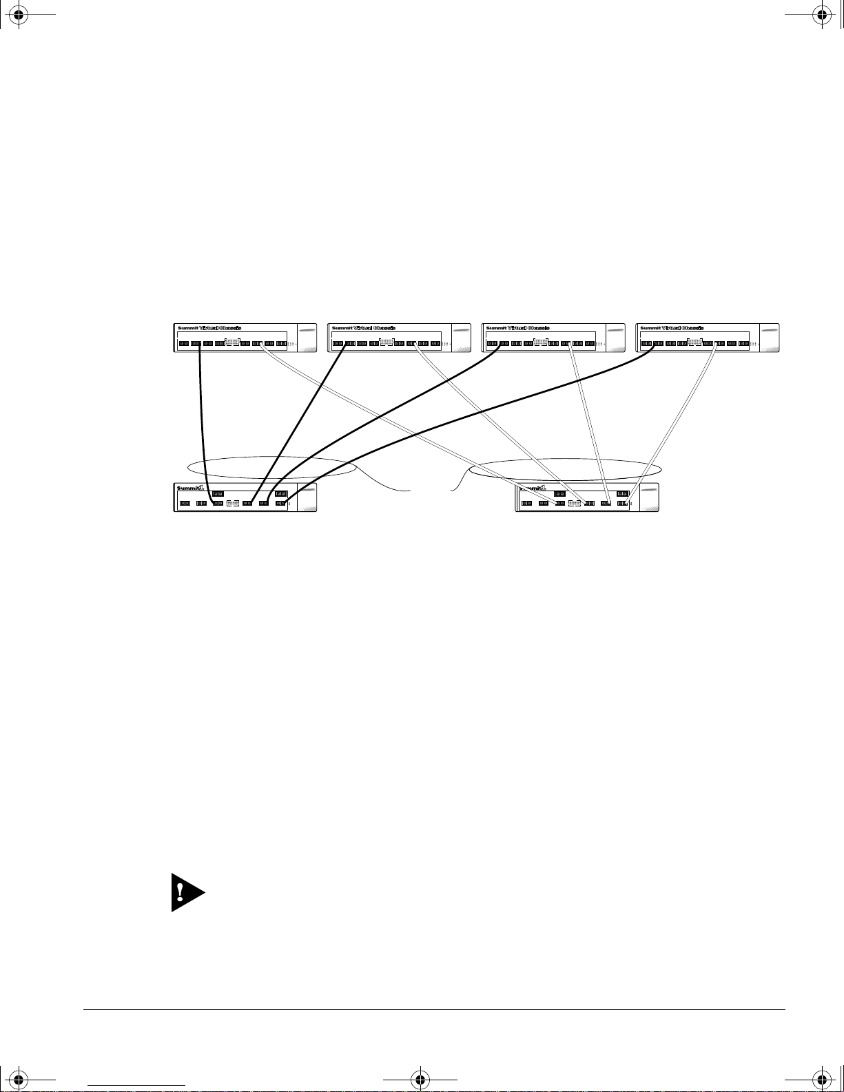
In a smaller detailed example show n in Figure 10, Switch A is cabled to four Summit
Vi rtual Chassis, labeled Chassis 1, Chassis 2, Chassis 3, an d Chassis 4. Switch B is also
cabled to the four Summit Virtual Chassis.
Chassis 1 Chassis 2 Chassis 3 Chassis 4
2341 6785 2341 6785 2341 6785 2341 6785
UPPORTED CONFIGURATIONS
S
2341567
Switch A
Figure 10:
Detailed example using four Vir tual Chassis units
8
4-port
load-sharing
groups
2341567
Switch B
8
Switch A uses port 2 on each Summit Virtual Chassis ; Switch B uses port 6. The port
connections between the Summit1 switches and the four Summit Virtual Chassis are as
follows:
• Port 4 on Switch A is cabl ed to port 2 on Chassis 1.
• Port 5 on Switch A is cabl ed to port 2 on Chassis 2.
• Port 6 on Switch A is cabl ed to port 2 on Chassis 3.
• Port 7 on Switch A is cabl ed to port 2 on Chassis 4.
• Port 4 on Switch B is cabled to po rt 6 on Chassis 1.
• Port 5 on Switch B is cabled to po rt 6 on Chassis 2.
• Port 6 on Switch B is cabled to po rt 6 on Chassis 3.
• Port 7 on Switch B is cabled to po rt 6 on Chassis 4.
Summit switch connectio n must be cabled to the same por t numbers on all
Summit Vir tual Chassis. If not, communication among the switches will not
operate properly.
UMMIT VIRTUAL CHASSIS DESIGN AND INSTALLATION GUIDE
S
13
Page 16
virtchas.book Page 14 Friday, May 29, 1998 10:08 AM
UPPORTED CONFIGURATIONS
S
C
OMBINING VIRTUAL CHASSIS STACKS
A Virtu al Chassis stack functio ns as a single entity. Multiple Virtual Chassis stacks can
be combined using traditiona l bridging and routing system design m ethods. For
example, when combining Virtual Chassis stacks, loops are not permitted unless they
use appropriate routing boundaries , or the Spanning Tree Protocol (STP).
Stacks can be combined in two ways. The first and most straightforward method uses
available Summit switch ports in each stack to interconnect the stacks. When using this
method, you must follow th e same rules for connecting any Summ it switch, including
load-sharing rules, port redundancy rules, and so on .
The second method uses a Sum mit switch that is a memb er of both Virtual Chassis
stacks. Using this method, yo u must adhere to the requirements of both stacks when
connecting the switch. For example, a single port is used for connecting to a single
Vi rtual Chassis stack; two ports are used for connecting to a parallel Virtual Chassis
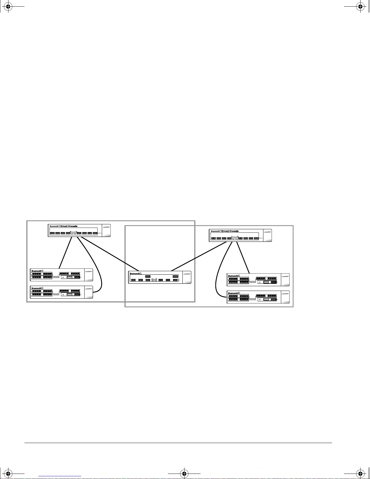
stack that has two S ummit Virtual Chassis. Figure 11 shows two single Virtua l Chassis
stacks connected using a Sum mit1. The Summit1 is a mem ber of both stacks.
Stack 2Stack 1
Figure 11:
Combining Vir tual Chassis stacks
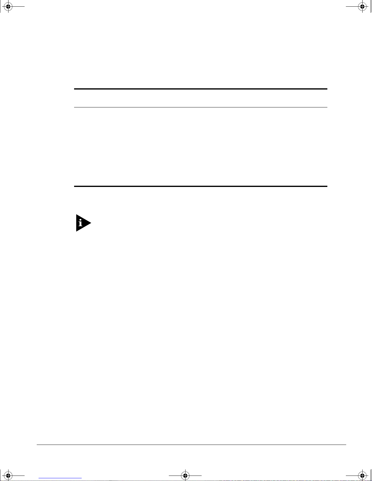
Table 2 describes Summit switch support for the various Virtual Chassis stack
configurations. The parallel Virtual Chassis stack informat ion is identical to the
load-sharing port configurations supported on Gigabit Ethernet ports for the Summit
switch family.
14 S
UMMIT VIRTUAL CHASSIS DESIGN AND INSTALLATION GUIDE
Page 17
virtchas.book Page 15 Friday, May 29, 1998 10:08 AM
UPPORTED CONFIGURATIONS
S
Ta b l e 2 :
Summit1
Summit2
Summit3
Summit4
Summit48
*Can result in a lack of connectivity if a single failure occurs in the stack. Refer to the section, “Configurations
to Avoid,” for more information.
Summit Switc h Suppor t for Virtual Chas sis Stacks
Single Virtual
Chassis Stack
Any of ports 1 - 8 Ports 2 and 3, or
Port 17 or Port 18 Ports 17 and 18 Not supp orted*
Port 25 Not supp orted* Not supported *
Any of ports 17 - 22 Ports 17 and 18, or
Port 49 or Port 50 Ports 49 and 50 Not supp orted*
Parallel Virtual
Chassis Stack (2)
Ports 4 and 5, or
Ports 6 and 7
Ports 19 and 20, or
Ports 21 and 22
Parallel Virtual Chassis
Stack (4)
Ports 4, 5, 6, and 7
Ports 19, 20, 21, and 22
You must configure the Summit por ts that will be u sed to connect to the Summit
Vir tual Chas sis. For information on c onfigur ing S ummit ports, refer to the
Switch Instal lation and User Guide
ONFIGURATIONS TO AVOID
C
.
Summit
Some Virtual Chassis configurations may appear to work, but are not supported
because their redundancy capabilities are qu ite limited. The following section has an
example of this situation.
A
DDING A SUMMIT
3 S
WITCH TO A PARALLEL VIRTUAL CHASSIS STACK
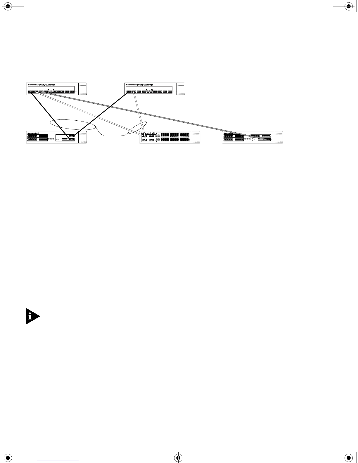
The Summit3 switch has one active Gigabit Ethernet port. Therefore, it can have one
active connection to a Summit Virtual Chassis. Figure 12 shows how you would add a
Summit3 to the example used in the parallel Virtual Chassis example using Summit 2
switches, shown previously in Figure 8.
UMMIT VIRTUAL CHASSIS DESIGN AND INSTALLATION GUIDE
S
15
Page 18
virtchas.book Page 16 Friday, May 29, 1998 10:08 AM
UPPORTED CONFIGURATIONS
S
2-port
Switch A
load-sharing
groups
Chassis 2Chassis 1
Switch CSwitch B
Figure 12:
Adding a Summit 3 switch to the parallel Vir tual Chassis s tack example
In Figure 12, the two Summit2 switches are connected to port 1 and port 2 of both
Summit Virtual Chassis. The Summit3 can conn ect to port 3 on one of the Summit
Virtual Chassis. Port3 of the other Summit Virtual Chassis must not be connected to any
other Summit switch. Doing so can cause frames to be delivered to the wrong device.
The port connections between the Summit switches and the Summit Virtual Chassis
shown in Figure 12 are as follows:
• Port 17 on Switch A is cabled to port 1 on Chassis 1.
• Port 18 on Switch A is cabled to port 1 on Chassis 2.
• Port 49 on Switch B is cabled to port 2 on Chassis 1.
• Port 50 on Switch B is cabled to port 2 on Chassis 2.
• Port 25 on Switch C is cabled to port 3 on Ch assis 1.
• Nothing is cabled to port 3 o n Chassis 2.
Connecting a device to po rt 3 on Ch assis 2 can resu lt in frames being delivered
to the wrong switch.
Only Switch A and Switch B benefit from the load-sha ring and redundancy capabilities
of the parallel Virtual Chassis configuration. If either Switch A o r Switch B loses its
connection to Chassis 1, traffic is no long er be able to reach Switch 3, because Switch 3
is not connected to Chassis 2.
16 S
UMMIT VIRTUAL CHASSIS DESIGN AND INSTALLATION GUIDE
Page 19
virtchas.book Page 17 Friday, May 29, 1998 10:08 AM
The same situation can occur i f a Summit2 or a Summit 48 is used in a parallel Virtual
Chassis stack that consi sts of four Summit Virtual Chassis. Only Summit switches t hat
support four links benefit from the redundancy capabilities. If sp ecific links to other
switches fail, the Summit2 ca n lose partial connectivity to the sta ck.
ONFIGURING SUMMIT SWITCHES FOR USE WITH THE VIRTUAL CHASSIS
C
ONFIGURING SUMMIT SWITCHES FOR
C
IRTUAL
V
The Summit Virtual chassis requires no configuration and has no user interfa ce. You
must configure each Summit switch that will be attached to a Sum mit Vi rtual Chassis.
Several important aspects of conf iguring the Summit switch for use with a Summit
Virtual Chass is are detailed in the Summit Installation and User Guide. These include the
following:
• You must configure the Summit swi tch port(s) prior to connecting the switch to the
Summit Virtual Chassis . Each connected port must be configured as a SummitLink
port. If you are using a parallel Virtual Chassis stack, you must confi gure
load-sharing on the Summit switch after the ports are designated as SummitLink
ports.
• Summit switches exchange info rmation across Virtual Chassis links for the purpose
of automatically joinin g Virtual LANs (VLANs). A VLAN is automatically joined
between Summit switches that a re members of the same Virtual Chassis stack if the
VLAN name and configured 802.1Q tag values are identical.
The default VLAN on all Summit switches is joined through a Vir tual Chassis
stack because the VL AN name is the s ame (
value is
HASSIS
C
1
on each switch.
Default
USE
), and the explicit 802.1Q tag
WITH THE
UMMIT VIRTUAL CHASSIS DESIGN AND INSTALLATION GUIDE
S
17
Page 20
virtchas.book Page 18 Friday, May 29, 1998 10:08 AM
NSTALLING THE SUMMIT VIRTUAL CHASSIS
I
NSTALLING THE SUMMIT VIRTUAL
I
HASSIS
C
To install the Summit Virtual Chassis, follow these steps :
1 Mount the Summit Virtual Chassis in the equipment rack, or, if it will be located on
a table, place the rubber feet on the bottom of the Summit Virtual Chassis.
For more information on install ing the mounting brackets, refer to the
Switch Instal lation and User Guide
.
Summit
2 If you are using the RPS ports on the Su mmit Virtual Chassis to connect one or two
Summit switches, do the following:
a Using the supplied cables, connect the RPS port on the Summit Virtual Chassis to
the RPS port on each Summ it switch.
The RPS DC cable must be connected to the Summit switch prior to co nnecting
the AC power cord to the Summit Vir tual Chas sis.
b Tighten the screws connecting both sides of the RPS cable.
Ensure that the cable is secur ed and is making good co ntact prior to tur ning on
the Summit Vir tual Ch assis.
c Connect an AC power cord to each power socket.
d Plug the power cords into properly grounded AC outlets.
When disconnecti ng the Summit Vir tual chassis, the AC power cords must be
removed from the Summit Vir tual Chassis be fore removing the RPS DC cables.
3 Connect the fiber-optic cable between each Summit switch port and each Summit
Virtual Chass is port.
If you are cabling a single Summit sw itch to two Summit Virtual Chassis in a
parallel configuration, ensure that you cable each switch port to the same port
number on the two different Summit Virtual Chassis.
18 S
UMMIT VIRTUAL CHASSIS DESIGN AND INSTALLATION GUIDE
Page 21
virtchas.book Page 19 Friday, May 29, 1998 10:08 AM
ECHNICAL SPECIFICATIONS
T
ECHNICAL SPECIFICATIONS
T
Physical Dimensions
Environmental Requirements
Operating Temperature
Storage Temperature
Operating Humidity
Regulatory Compliance
Heat Dissipation
Power supply
AC Line Frequency
Input Voltage Options
Current Rating
Height: 3 .5 inches x Width: 17 .32 inche s x Depth: 17.42
inches
Weight: 18 lb (8.17 kg)
0 to 50 degrees C
-20 to 80 degrees C
5% to 95% relative humidity, noncondensing
EN55022 Class B
FCC part 15 Class A
CSA C108.8-M1983 (A)
VCCI Class 2
EN50082-1 (IEC 801 Parts 2-4)
EN61000 -3 -2
EN61000 -4 -3
EN61000 -4 -5
EN61000 -4 -6
EN61000 -4 -11
UL 1950 3rd Edition
CSA 22.2 #950
EN60950:1992/A3:1995
TUV GS (Rheinland)
CE Mark
236W maximum (6 82.4 BTU/hr ma ximum)
47Hz to 6 3Hz
90VAC to 132VAC, 180VAC to 264VAC auto-selecting
100-120/200-240 VAC 4.0/2.0 A (for each power socket
input/power supply)
UMMIT VIRTUAL CHASSIS DESIGN AND INSTALLATION GUIDE
S
19
Page 22
virtchas.book Page 20 Friday, May 29, 1998 10:08 AM
ECHNICAL SPECIFICATIONS
T
20 S
UMMIT VIRTUAL CHASSIS DESIGN AND INSTALLATION GUIDE
 Loading...