

Extreme Networks Summit Summit1, Summit2 Installation And User Manual

SUMMIT.BK Page i Thursday, September 25, 1997 12:33 PM
Summit Switch
Installation and User
Guide
Extreme Networks, Inc.
10460 Bandley Drive
Cupertino, California 95014
(888) 257-3000
http://www.extremenetworks.com
Published September 1997

SUMMIT.BK Page ii Thursday, September 25, 1997 12:33 PM
Copyright ©
reproduced in any form or by any means or used to make any derivative work (such as translation,
transformation, or adaptation) without permission from Extreme Networks, Inc.
Extreme Networks, ExtremeWare, Summit, and the Extreme Networks logo are trademarks of Extreme
Networks.
All other brand and product names are registered trademarks or trademarks of their respective
holders.
Extreme Networks, Inc., 1997.
All rights reserved. No part of this documentation may be
ii

SUMMIT.BK Page i Thursday, September 25, 1997 12:33 PM
REFACE
P
This preface provides an overview of this guide, describes guide conventions, tells you
where to look for speciÞc information and lists other publications that may be useful.
NTRODUCTION
I
This guide provides the required information to install and conÞgure the Summit1 and
Summit2 Gigabit Ethernet Switch.
This guide is intended for use by network administrators who are responsible for
installing and setting up network equipment. It assumes a basic working knowledge of
¥
Local Area Networks (LANs)
¥
Ethernet concepts
¥
Ethernet switching and bridging concepts
¥
Simple Network Management Protocol (SNMP)
If the information in the Release Notes shipped with your Switch differs from the
information in this guide, follow the Release Notes.
ERMINOLOGY
T
When features, functionality, or operation is speciÞc to a particular model of the
Summit family, the model name is used (for example, Summit1 or Summit2).
UMMIT SWITCH INSTALLATION AND USER GUIDE I
S

SUMMIT.BK Page ii Thursday, September 25, 1997 12:33 PM
Explanations about features and operations that are the same among all members of the
Summit family simply refer to the product as the Summit.
ONVENTIONS
C
Table 1 and Table 2 list conventions that are used throughout this guide.
Table 1:
Icon
Notice Icons
Notice Type Alerts you to...
Note
Important features or instructions.
Caution Risk of personal injury, system damage,
or loss of data.
Warning Risk of severe personal injury.
Table 2:
Convention
Screen displays
The words “enter”
and “type”
Text Conventions
Description
This typeface represents information as it appears on the screen
When you see the word “enter” in this guide, you must type
something, and then press the Return or Enter key. Do not press the
Return or Enter key when an instruction simply says “type.”
[Key] names Key names appear in text in one of two ways:
■
Referred to by their labels, such as “the Return key” or “the
Escape key”
■
Written with brackets, such as [Return] or [Esc]
If you must press two or more keys simultaneously, the key names
are linked with a plus sign (+). Example:
Press [Ctrl]+[Alt]+[Del].
Words in
italicized
type
Italics emphasize a point or denote new terms at the place where
they are defined in the text.
Words in
boldface
type Bold text denotes key features.
.
II
S
UMMIT SWITCH INSTALLATION AND USER GUIDE

SUMMIT.BK Page iii Thursday, September 25, 1997 12:33 PM
The command syntax is explained in Chapter 4.
ELATED PUBLICATIONS
R
The Summit documentation set includes the following:
¥
Summit Quick Reference Guide
¥
Summit Release Note
You may Þnd the following Web site of interest:
¥
Extreme Networks Home Page: http://www.extremenetworks.com/
ELATED PUBLICATIONS
R
UMMIT SWITCH INSTALLATION AND USER GUIDE III
S

SUMMIT.BK Page iv Thursday, September 25, 1997 12:33 PM
IV
S
UMMIT SWITCH INSTALLATION AND USER GUIDE

SUMMIT.BK Page 1 Thursday, September 25, 1997 12:33 PM
1
Summit Overview
This chapter describes the following:
¥
Summit1 and Summit2 features
¥
How to use the Summit family of switches in your network conÞguration
¥
Summit front views
¥
Summit rear view
¥
Factory default settings
BOUT THE SUMMIT FAMILY OF SWITCHES
A
Network managers are currently faced with the challenge of creating networks that can
provide ultra-fast speed and high performance to serve the needs of todayÕs network
users, while simultaneously preserving the investment they have made in Ethernet and
Fast Ethernet technology.
By addressing the entire spectrum of Ethernet data rates (10/100/1000 Mbps), the
Summit family of LAN switches enables you to introduce high-speed Gigabit Ethernet
backbones into your existing network, while maintaining established connections to the
10 Mbps and 100 Mbps segments that already exist.
UMMIT SWITCH INSTALLATION AND USER GUIDE
S
1-1

SUMMIT.BK Page 2 Thursday, September 25, 1997 12:33 PM
UMMIT OVERVIEW
S
UMMARY OF FEATURES
S
The Summit family of switches is comprised of two models: the Summit1 and the
Summit2.
Both switches have the following features:
¥
Support for 128K addresses in the Switch forwarding database
¥
Fully nonblocking operation
Ñ
All ports transmit and receive packets at wire speed
¥
Autonegotiation for half- or full-duplex operation
¥
Optional redundant power supply
¥
Redundant physical Gigabit Ethernet backbone connection
¥
Virtual local area networks (VLANs) including support for 802.1Q
¥
Quality of Service (QoS)
¥
Spanning Tree Protocol (STP) (IEEE 802.1D) with multiple STP domains
¥
Wirespeed Internet Protocol (IP) routing via Routing Information Protocol (RIP)
version 1 and RIP version 2
¥
Integrated network management
¥
Console connection
¥
Telnet connection
¥
Web interface
¥
Simple Network Management Protocol (SNMP) support
P
ORT CONNECTIONS
The Summit1 provides eight Gigabit Ethernet ports. Six of the ports are Þxed
1000Base-SX ports using 850nm duplex SC connectors. Two of the ports are modular,
and support the standard Gigabit Interface Connector (GBIC). This enables you to select
various types of Þber and copper modules to support longer distances or lower cost.
The Summit1 can be ordered with either two 1000Base-SX or two 1000Base-LX GBIC
transceivers already installed. GBIC transceivers can also be ordered separately.
1-2 S
UMMIT SWITCH INSTALLATION AND USER GUIDE
SUMMIT.BK Page 3 Thursday, September 25, 1997 12:33 PM
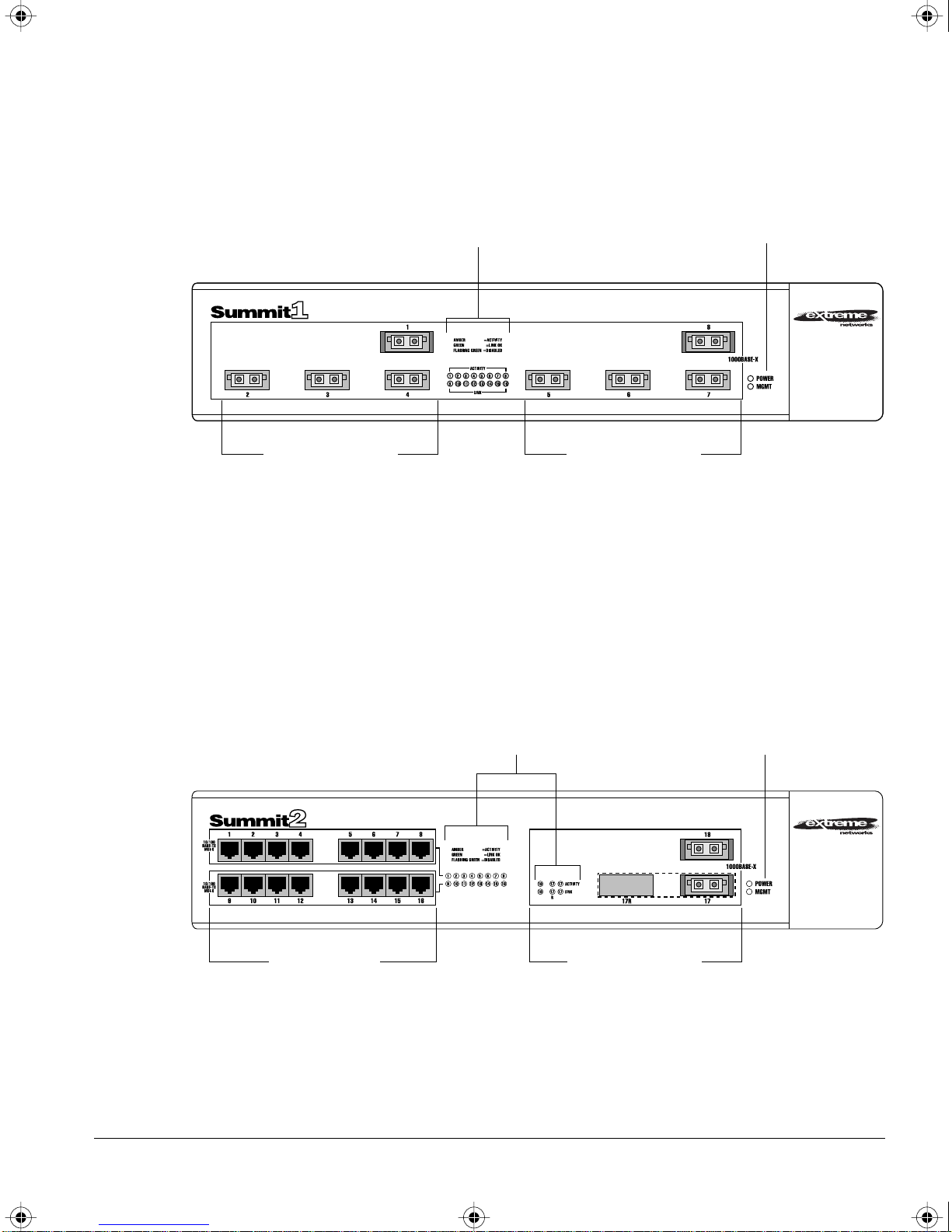
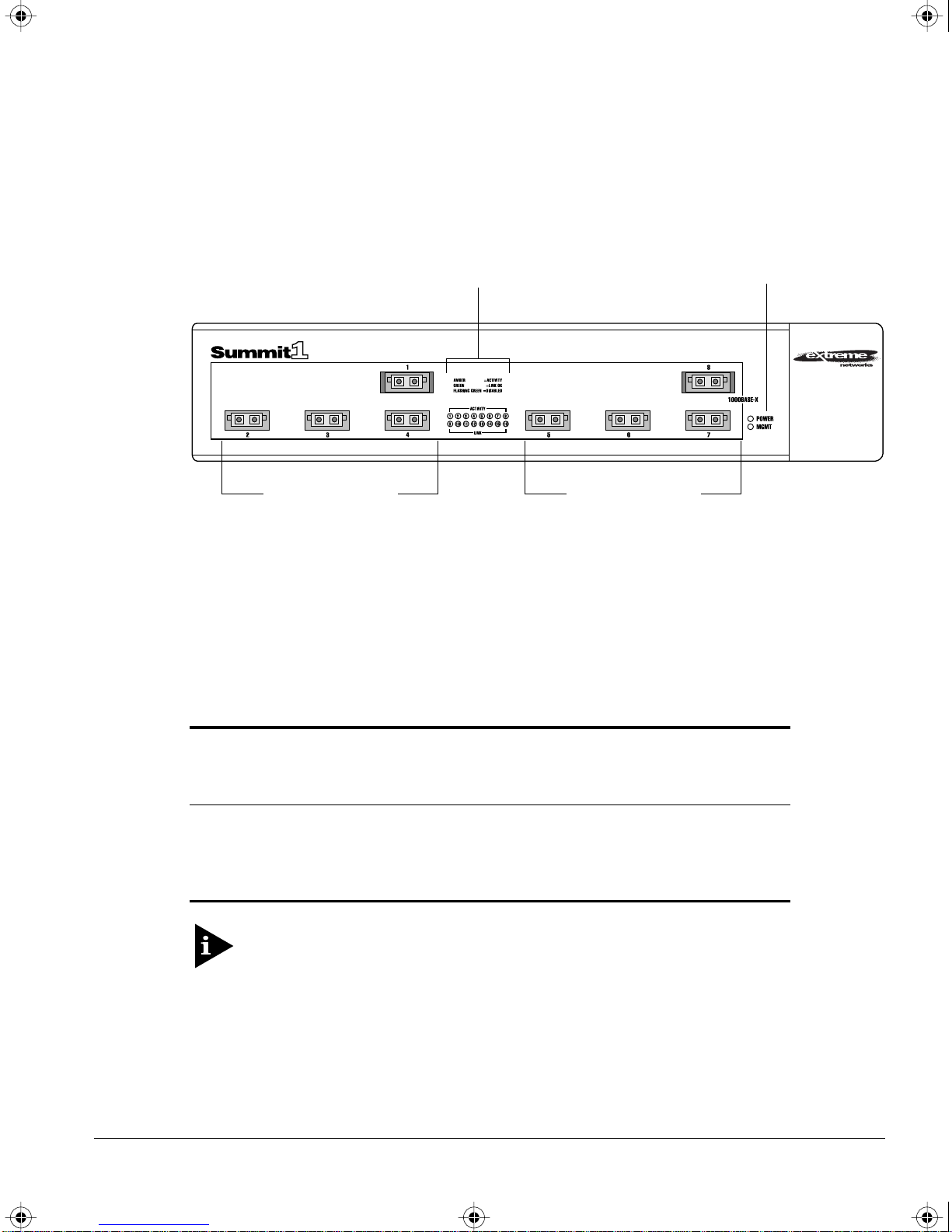
Figure 1-1 shows the front view of the Summit1.
UMMARY OF FEATURES
S
Unit status LEDs
Gigabit Ethernet ports
Port status LEDs
Gigabit Ethernet ports
Figure 1-1: Summit1 front view
The Summit2 is a workgroup switch featuring sixteen 10Base-T/100Base-TX ports, two
Gigabit Ethernet uplinks, and one redundant Gigabit Ethernet uplink. The
10Base-T/100Base-TX ports use standard RJ-45 connectors. They are autosensing for
10/100 Mbps operation, as well as half- or full-duplex operation. The Gigabit Ethernet
interfaces support the GBIC connector, and ship with standard 1000Base-SX, 850nm
GBIC modules. Additional cable types are also supported.
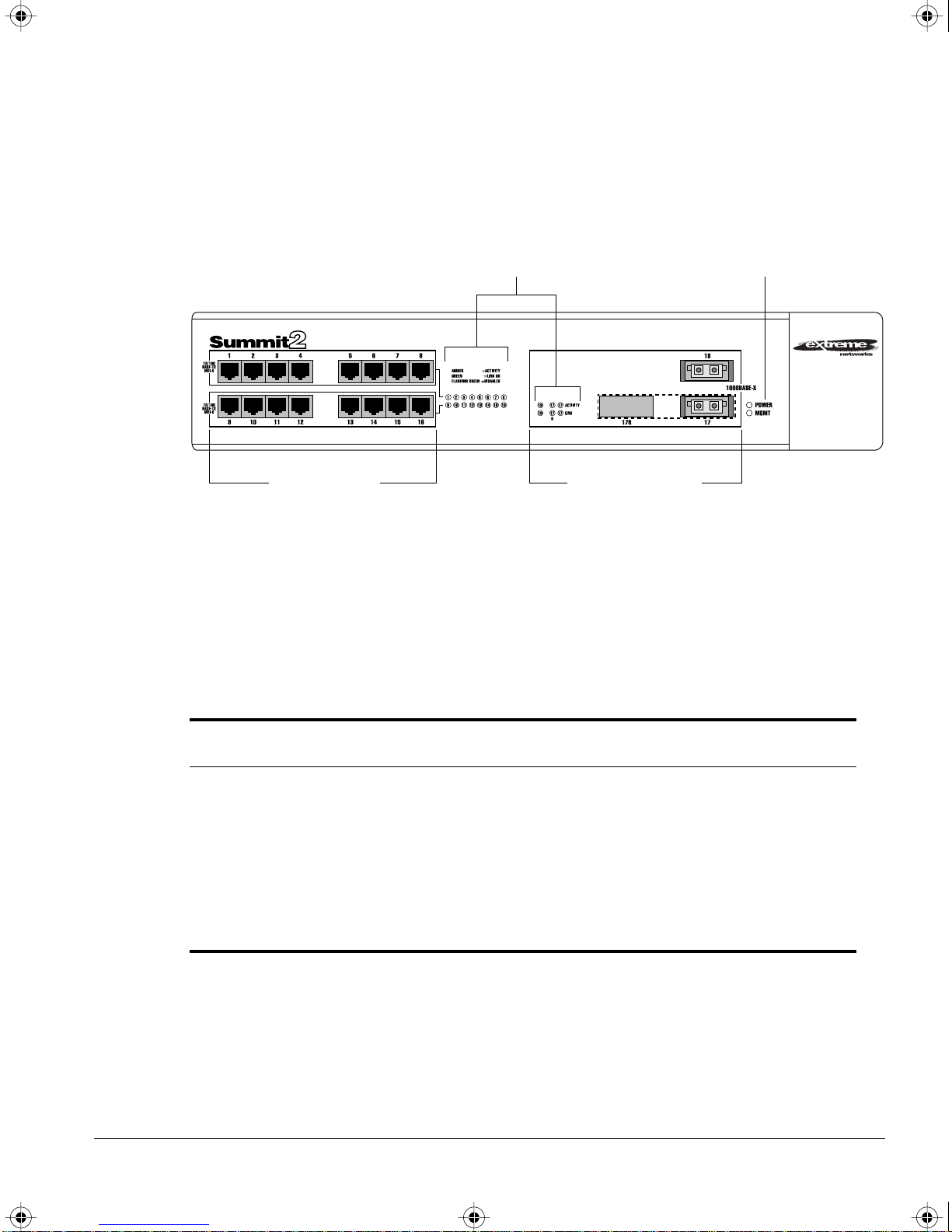
Figure 1-2 shows the front view of the Summit2
Port status LEDs
10/100 Mbps ports
Figure 1-2: Summit2 front view
Unit status LEDs
Gigabit Ethernet ports
UMMIT SWITCH INSTALLATION AND USER GUIDE
S
1-3
SUMMIT.BK Page 4 Thursday, September 25, 1997 12:33 PM
S
UMMIT OVERVIEW
FULL-DUPLEX
The Summit Switch provides full-duplex support for all ports. Full-duplex allows
frames to be transmitted and received simultaneously and, in effect, doubles the
bandwidth available on a link. All 10/100 Mbps ports on the Summit autonegotiate for
half- or full-duplex operation.
PORT REDUNDANCY
The Summit2 has an optional redundant Gigabit Ethernet port. Using the redundant
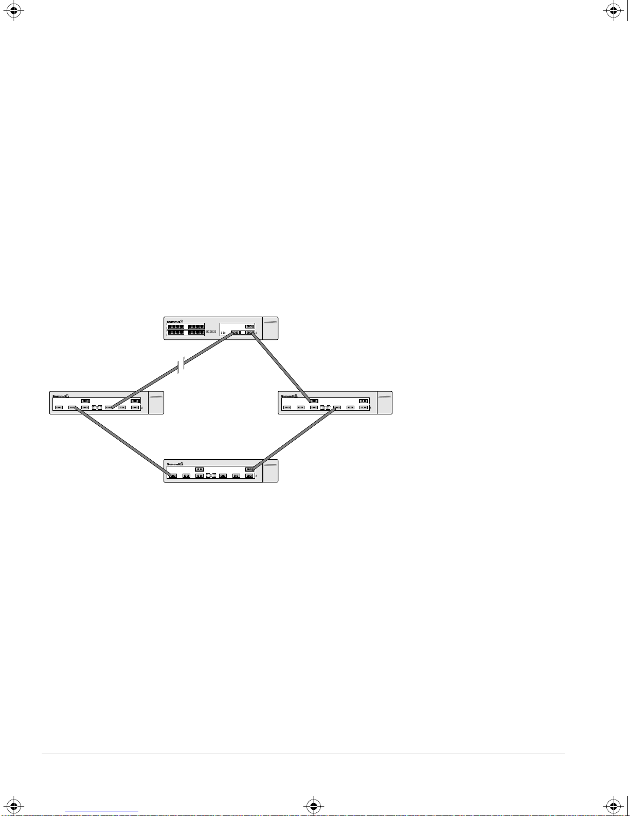
port, you can dual-home the Summit2 to one or two Switches. Figure 1-3 illustrates a
Summit2 dual-homed to two different Switches.
Dual-homed
Backup
Active
Figure 1-3: Dual-homing configuration
In the event that the active port fails or loses link status, the redundant port is
automatically activated. When the primary port resumes operation, the redundant port
becomes inactive. The redundant port cannot be used for load sharing.
VIRTUAL LANS (VLANS)
The Summit has a VLAN feature that enables you to construct your broadcast domains
without being restricted by physical connections. Up to 255 VLANs can be deÞned on
the Summit. A VLAN is a group of location- and topology-independent devices that
communicate as if they were on the same physical local area network (LAN).
Implementing VLANs on your network has the following three advantages:
1-4 SUMMIT SWITCH INSTALLATION AND USER GUIDE

SUMMIT.BK Page 5 Thursday, September 25, 1997 12:33 PM
¥ It helps to control broadcast trafÞc. If a device in VLAN marketing transmits a
broadcast frame, only VLAN marketing devices receive the frame.
¥ It provides extra security. Devices in VLAN marketing can only communicate with
devices on VLAN sales using a device that provides routing services.
¥ It eases the change and movement of devices on networks. If a device in VLAN
marketing is moved to a port in another part of the network, all you must do is
specify that the new port belongs to VLAN marketing.
For more information on VLANs, refer to Chapter 5.
SPANNING TREE PROTOCOL (STP)
S
UMMARY OF FEATURES
The Summit supports the IEEE 802.1D Spanning Tree Protocol (STP), which is a
bridge-based mechanism for providing fault tolerance on networks. STP enables you to
implement parallel paths for network trafÞc, and ensure the following:
¥ Redundant paths are disabled when the main paths are operational.
¥ Redundant paths are enabled if the main trafÞc paths fail.
The Summit supports up to 64 Spanning Tree Domains (STPDs).
For more information on STP, refer to Chapter 7.
QUALITY OF SERVICE (QOS)
The Summit has Quality of Service (QoS) features that enable you to specify service
levels for different trafÞc groups. By default, all trafÞc is assigned with the ÒnormalÓ
QoS proÞle. If needed, you can conÞgure some trafÞc to have different guaranteed
minimum bandwidth, maximum bandwidth, and priority.
For more information on Quality of Ser vice, refer to Chapter 8.
SUMMIT SWITCH INSTALLATION AND USER GUIDE 1-5

SUMMIT.BK Page 6 Thursday, September 25, 1997 12:33 PM
S
UMMIT OVERVIEW
IP UNICAST ROUTING
The Summit can route IP trafÞc between the VLANs that are conÞgured as virtual
router interfaces. Both dynamic and static IP routes are maintained in the routing table.
RIP version 1 and RIP version 2 are supported.
For more information on IP unicast routing, see Chapter 9.
NETWORK CONFIGURATION EXAMPLES
This section describes where to position the Summit1 and Summit2 within your
network.
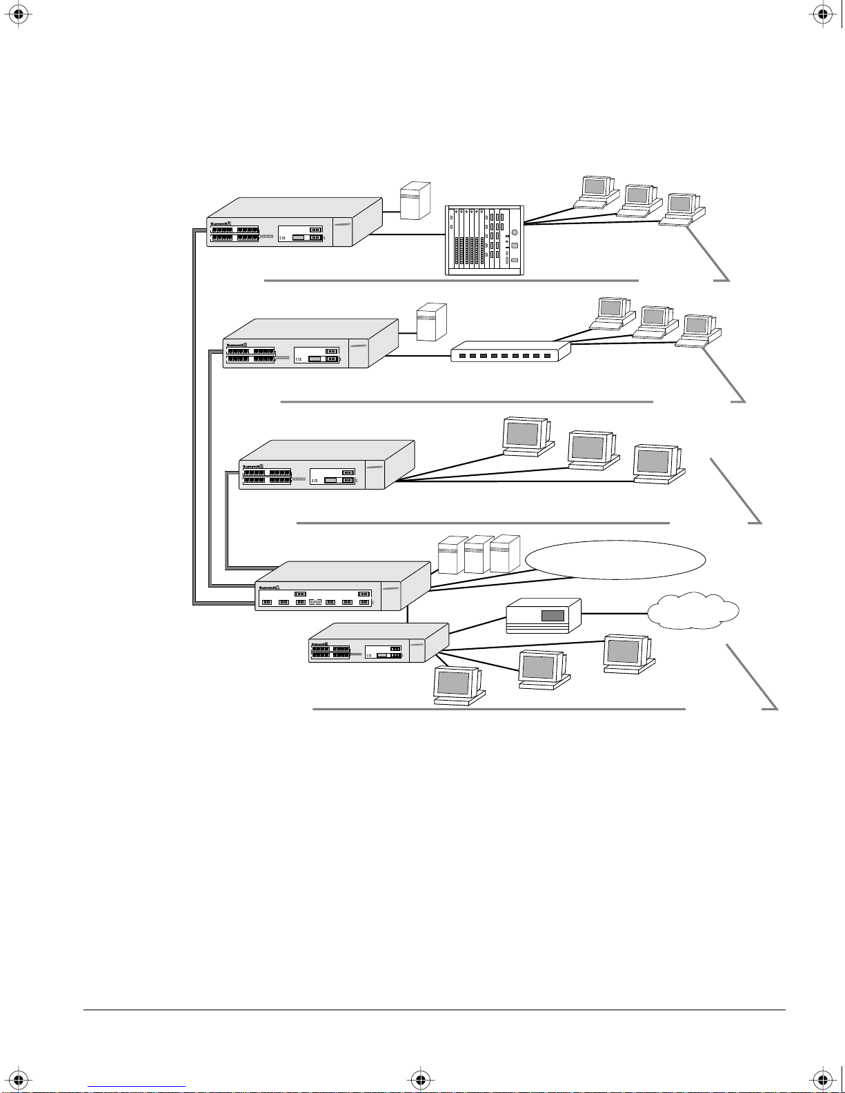
One common use of the Summit is on a Gigabit Ethernet backbone. Figure 1-4 shows an
example of a Gigabit Ethernet backbone within a building.
1-6 SUMMIT SWITCH INSTALLATION AND USER GUIDE
SUMMIT.BK Page 7 Thursday, September 25, 1997 12:33 PM
N
ETWORK CONFIGURATION EXAMPLES
Regional wiring closet
Regional wiring closet
Power workgroup
Gigabit Ethernet risers
Backbone
Workgroup
hubs
PCs
4th floor
Workgroup
switches
PCs
3rd floor
Workstations
2nd floor
Meshed campus backbone
Router
Internet
Workstations
1st floor
Figure 1-4: Summit family used in a backbone configuration
The Summit2 on each ßoor is connected to the backbone Summit1 using a 1 Gbps,
full-duplex link. Using Gigabit Ethernet as a backbone technology removes bottlenecks
by providing scalable bandwidth, low-latency, high-speed data switching.
As well as providing a fast-switched backbone between Ethernet LANs, Gigabit
Ethernet-equipped Þle servers and devices may be directly attached to the Summit1,
providing improved performance to the Ethernet desktop.
SUMMIT SWITCH INSTALLATION AND USER GUIDE 1-7
SUMMIT.BK Page 8 Thursday, September 25, 1997 12:33 PM
S
UMMIT OVERVIEW
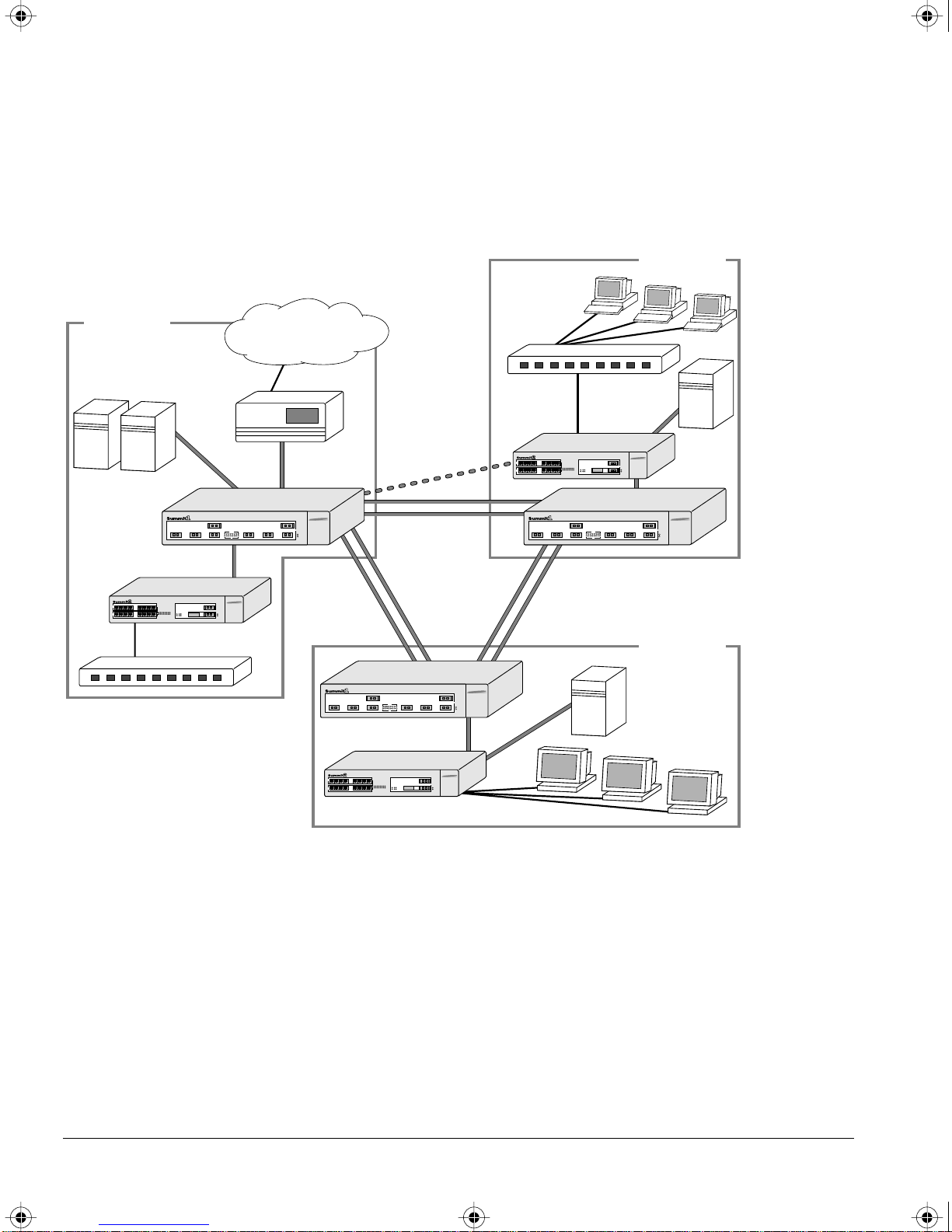
Another common use for the Summit family is in a campus environment, as shown in
Figure 1-5.
Building 2
PCs
Building 1
Intranet/Internet
Load-
balanced
links
Dual-homing
Meshed
backbone
Building 3
Figure 1-5: Summit family used in a campus environment
The Summit1 switches located in each building form a meshed backbone, providing
load balancing and redundancy. In addition, the Summit2 Switch in Building 2 is
dual-homed to the Summit1 located in Building 1 and to the Summit1 located in
Building 2.
1-8 SUMMIT SWITCH INSTALLATION AND USER GUIDE
Workstations
SUMMIT.BK Page 9 Thursday, September 25, 1997 12:33 PM
SUMMIT1 FRONT VIEW
Figure 1-6 shows the Summit1 front view.
S
UMMIT
1 F
RONT VIEW
Unit status LEDs
Gigabit Ethernet ports
Port status LEDs
Gigabit Ethernet ports
Figure 1-6: Summit1 front view
PORTS
The Summit1 has eight Gigabit Ethernet ports. Six of the ports use SC connectors and
support 1000Base-SX over 850nm Þber-optic cable. Ports 1 and 8 have GBIC connectors
and support the media types and distances listed in Table 1-1.
Table 1-1: Summit1 Supported Media Distances for GBIC Connectors
Distance
Gigabyte Type
850nm Multimode
50/125 micro
Multimode Fiber
550 Meters
62.5/125 micron
Multimode Fiber
260 Meters
Single-mode Fiber
Not supported
Optics
1300nm
550 Meters
440 Meters
3000 Meters
Single-mode Optics
For more information on 1000Base-SX and 1000Base-LX link characteristics,
refer to IEEE Draft P802.3z/D3.1, Table 38-8.
SUMMIT SWITCH INSTALLATION AND USER GUIDE 1-9

SUMMIT.BK Page 10 Thursday, September 25, 1997 12:33 PM
S
UMMIT OVERVIEW
LEDS
Table 1-2 describes the light emitting diode (LED) behavior on the Summit1.
Table 1-2: Summit1 LEDs
LED Color Indicates
Power Green
Yellow
MGMT Green flashing
■ Slow
■ Medium
■ Fast
Yellow
The Summit1 is powered up.
The Summit1 is indicating a power, overheat, or fan failure.
■ Power On Self Test (POST) in progress.
■ The Summit1 is operating normally.
■ Software download in progress.
The Summit1 has failed its POST.
Port Status LEDs
Packet Yellow
Off
Status Green on
Green flashing
Off
Frames are being transmitted/received on this port.
No activity on this port.
Link is present; port is enabled;
full-duplex operation.
Link is present; port is disabled.
Link is not present.
1-10 SUMMIT SWITCH INSTALLATION AND USER GUIDE
SUMMIT.BK Page 11 Thursday, September 25, 1997 12:33 PM
SUMMIT2 FRONT VIEW
Figure 1-7 shows the Summit2 front view.
S
UMMIT
2 F
RONT VIEW
10/100 Mbps ports
Port status LEDs
Gigabit Ethernet ports
Unit status LEDs
Figure 1-7: Summit2 front view
PORTS
The Summit2 has 16 autosensing 10Base-T/100Base-TX ports, two Gigabit Ethernet
ports, one of which has a redundant Gigabit Ethernet port. Table 1-3 describes the ports,
connectors, media, and maximum distances for each port type.
Table 1-3: Summit2 Supported Media
Maximum
Media Module (Ports) Connector Media
RJ-45 RJ-45 Category 5 Cable (at 100Mbps)
Distance
100 Meters
Category 3 Cable (at 10Mbps)
850nm Multimode Optics SC 50u/125 Multimode Fiber
62.5u/125 Multimode Fiber
1300nm Singlemode Optics SC 50u/125 Multimode Fiber
62.5u/125 Multimode Fiber
10u Singlemode Fiber
SUMMIT SWITCH INSTALLATION AND USER GUIDE 1-11
550 Meters
260 Meters
550 Meters
440 Meters
3000 Meters

SUMMIT.BK Page 12 Thursday, September 25, 1997 12:33 PM
S
UMMIT OVERVIEW
LEDS
Table 1-4 describes the LED behavior on the Summit2.
Table 1-4: Summit2 LEDs
LED Color Indicates
Power Green
Yellow
MGMT Green flashing
■ Slow
■ Medium
■ Fast
Yellow
The Summit2 is powered up.
The Summit2 is indicating a power, overheat, or fan failure.
■ Power On Self Test (POST) in progress.
■ The Summit2 is operating normally.
■ Software download in progress.
The Summit2 has failed its POST.
10/100Mbps Port Status LEDs
Green
Yellow
Green flashing
Off
Link is present; port is enabled.
Frames are being transmitted/received on this port.
Link is present; port is disabled.
Link is not present.
Gigabit Ethernet Port Status LEDs
Packet Yellow
Frames are being transmitted/received on this port.
No activity on this port.
Off
Status Green on
Link is present; port is enabled;
full-duplex operation.
Green flashing
Off
Link is present; port is disabled.
Link is not present.
1-12 SUMMIT SWITCH INSTALLATION AND USER GUIDE
SUMMIT.BK Page 13 Thursday, September 25, 1997 12:33 PM
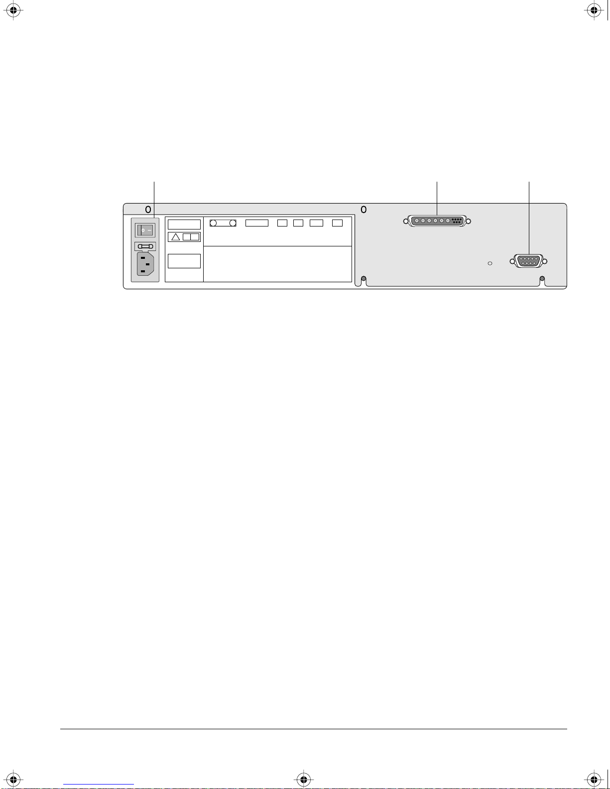
SUMMIT REAR VIEW
Figure 1-8 shows the rear view for the Summit1 and the Summit2.
U
C
L
!
MODEL/NUMBER
PART NUMBER
SERIAL NUMBER
130001-00 Rev.03
MAC ADDRESS
S
UMMIT REAR VIEW
Console portRPS portPower socket and fuse
U
L
MADE IN USA
Figure 1-8: Summit rear view
POWER SOCKET
The Summit automatically adjusts to the supply voltage. The power supply operates
down to 90 V. The fuse is suitable for both 110 V AC and 220-240 V AC operation.
SERIAL NUMBER
You may need this serial number for fault-reporting purposes.
CONSOLE PORT
Use the console port (9-pin, ÒDÓ type connector) for connecting a terminal and carrying
out local out-of-band management.
REDUNDANT POWER SUPPLY PORT
The redundant power supply (RPS) port is used to connect to a Summit RPS. The
Summit RPS provides a redundant power source to the Summit. If the primary power
source for the Switch fails, the Summit RPS takes over, ensuring uninterrupted network
operation.
In addition, when connected to a Summit RPS, the Summit Switch can provide status
on power and fan operation of the RPS through SNMP and the command-line interface.
The Summit RPS can simultaneously provide power for up to two Summit Switches.
SUMMIT SWITCH INSTALLATION AND USER GUIDE 1-13

SUMMIT.BK Page 14 Thursday, September 25, 1997 12:33 PM
S
UMMIT OVERVIEW
MAC ADDRESS
This label shows the unique Ethernet MAC address assigned to this device.
FACTORY DEFAULTS
Table 1-5 shows factory defaults for the Summit features.
Table 1-5: Summit Factory Defaults
Item Default Setting
Port status Enabled on all ports.
Serial or Telnet user account
Console port configuration 9600 baud, eight data bits, one stop bit, no parity, XON/XOFF
Web network management Enabled.
SNMP read community string public.
SNMP write community string private.
RMON history session Enabled.
RMON alarms Disabled.
BOOTP Enabled on the default VLAN (
QoS All traffic is part of the default queue.
802.1p priority Recognition enabled.
Virtual LANs One VLAN named
802.1Q tagging All packets are untagged on the default VLAN (
Spanning Tree Protocol Disabled; one STPD (s0).
IP Routing Disabled.
Forwarding database aging
period
admin
with no password and
flow control enabled.
default
VLAN. The default VLAN belongs to the STPD named
user
with no password.
default
).
; all ports belong to the default
default)
300 seconds (5 minutes).
s0
.
1-14 SUMMIT SWITCH INSTALLATION AND USER GUIDE

SUMMIT.BK Page 1 Thursday, September 25, 1997 12:33 PM
2
Installation and Setup
This chapter describes the following:
¥ How to decide where to install the Summit
¥ Gigabit Ethernet conÞguration rules
¥ How to install the Switch in a rack or free-standing
¥ How to connect equipment to the console port
¥ How to check the installation using the Power On Self-Test (POST)
FOLLOWING SAFETY INFORMATION
Before installing or removing any components of the Switch, or before carrying out any
maintenance procedures, you must read the safety information provided in Appendix A
of this guide.
DETERMINING THE SWITCH LOCATION
The Summit is suited for use in the ofÞce, where it can be free-standing or mounted in a
standard 19-inch equipment rack. Alternatively, the device can be rack-mounted in a
wiring closet or equipment room. Two mounting brackets are supplied with the Switch.
SUMMIT SWITCH INSTALLATION AND USER GUIDE 2-1

SUMMIT.BK Page 2 Thursday, September 25, 1997 12:33 PM
I
NSTALLATION AND SETUP
When deciding where to install the Switch, ensure that:
¥ The Switch is accessible and cables can be connected easily.
¥ Water or moisture cannot enter the case of the unit.
¥ Air-ßow around the unit and through the vents in the side of the case is not
restricted. You should provide a minimum of 25mm (1-inch) clearance.
¥ No objects are placed on top of the unit.
¥ Units are not stacked more than four high if the Switch is free-standing.
CONFIGURATION RULES
The connectors, supported media types, and maximum distances for the Summit family
are described in Chapter 1.
INSTALLING THE SUMMIT
The Summit can be mounted in a rack, or placed free-standing on a tabletop.
RACK MOUNTING
The Switch is 2U high and will Þt in most standard 19-inch racks.
The rack mount kits must not be used to suspend the Switch from under a table
or desk, or attach it to a wall.
To rack mount the Summit, follow these steps:
1 Place the Switch the right way up on a hard ßat surface, with the front facing
toward you.
2 Remove the existing screws from the sides of the chassis and retain for Step 4.
3 Locate a mounting bracket over the mounting holes on one side of the unit.
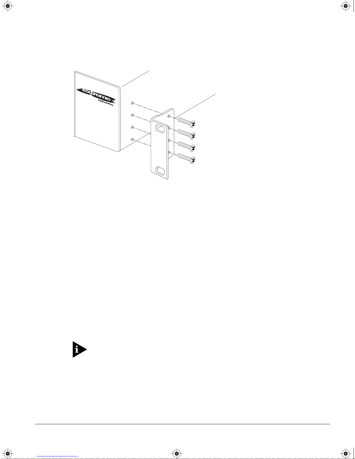
4 Insert the four screws and fully tighten with a suitable screwdriver, as shown in
Figure 2-1.
2-2 SUMMIT SWITCH INSTALLATION AND USER GUIDE
SUMMIT.BK Page 3 Thursday, September 25, 1997 12:33 PM
I
NSTALLING THE SUMMIT
Figure 2-1: Fitting the mounting bracket
5 Repeat the three previous steps for the other side of the Switch.
6 Insert the Switch into the 19-inch rack and secure with suitable screws (not
provided). Ensure that ventilation holes are not obstructed.
7 Connect the Summit to the redundant power supply (if applicable).
8 Connect cables.
FREE-STANDING
The Summit is supplied with four self-adhesive rubber pads. Apply the pads to the
underside of the device by sticking a pad in the marked area at each corner of the
Switch.
STACKING THE SWITCH AND OTHER DEVICES
Up to four units can be placed on top of one another.
This section relates only to physically placing the devices on top of one another.
The Switch does not form a stack (that is, a number of devices linked together
with special expansion cables to form a single logical device).
Apply the pads to the underside of the device by sticking a pad in the marked area at
each corner of the Switch. Place the devices on top of one another, ensuring that the
pads of the upper device line up with the recesses of the lower device.
SUMMIT SWITCH INSTALLATION AND USER GUIDE 2-3
SUMMIT.BK Page 4 Thursday, September 25, 1997 12:33 PM
I
NSTALLATION AND SETUP
CONNECTING EQUIPMENT TO THE CONSOLE PORT
Connection to the console port is used for direct local management. The Switch console
port settings are set as follows:
¥ Baud rate Ñ 9600
¥ Data bits Ñ 8
¥ Stop bit Ñ 1
¥ Parity Ñ None
¥ Flow control Ñ XON/XOFF
The terminal connected to the console port on the Switch must be conÞgured with the
same settings. This procedure will be described in the documentation supplied with the
terminal.
Appropriate cables are available from your local supplier. In order to make your own
cables, pin-outs for a DB-9 male console connector are described in Table 2-1.
Table 2-1: Console Connector Pin-Outs
Function Pin Number
TXD (transmit data) 3
RXD (receive data) 2
GND (ground) 5
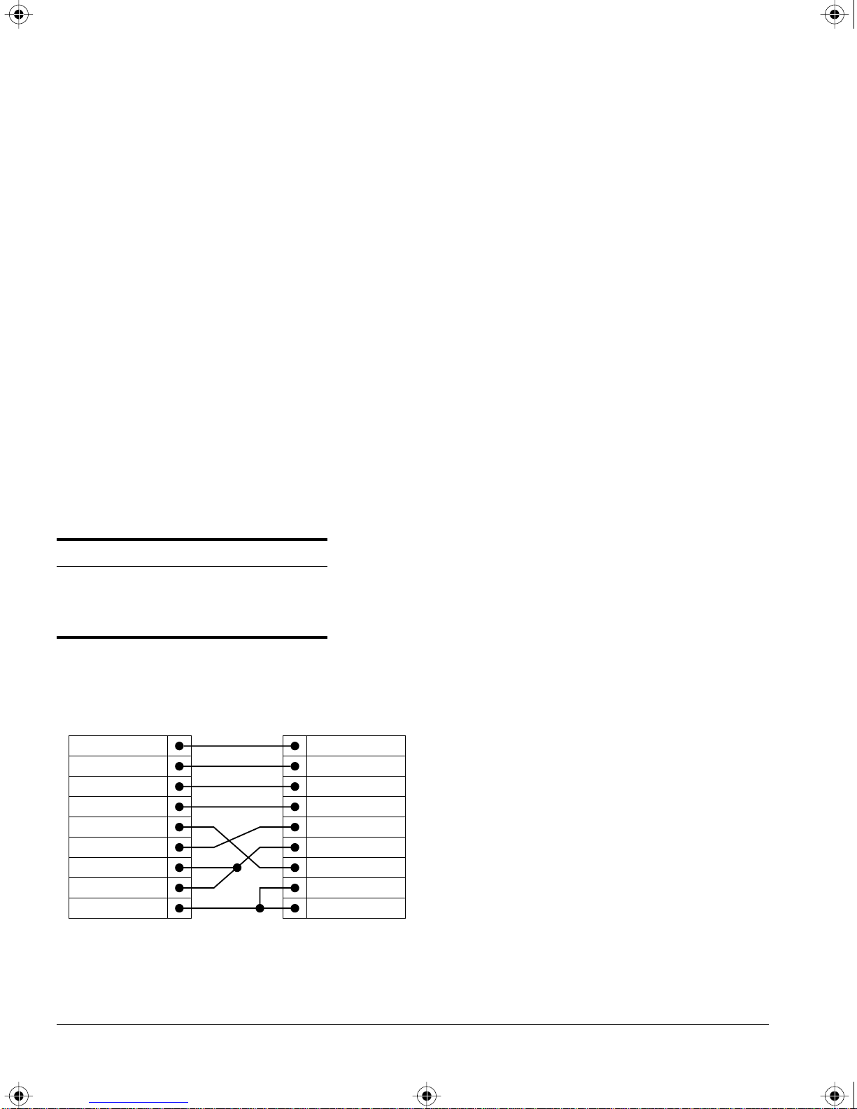
Figure 2-2 shows the pin-outs for a 9-pin to RS-232 25-pin null-modem cable.
Summit
Cable connector: 9-pin female
Screen
TxD
RxD
Ground
RTS
CTS
DSR
DCD
DTR
Shell
3
2
5
7
8
6
1
4
PC/Terminal
Cable connector: 25-pin male/female
Screen
1
3
2
7
4
20
5
6
8
RxD
TxD
Ground
RTS
DTR
CTS
DSR
DCD
Figure 2-2: Null-modem cable pin-outs
2-4 SUMMIT SWITCH INSTALLATION AND USER GUIDE
SUMMIT.BK Page 5 Thursday, September 25, 1997 12:33 PM
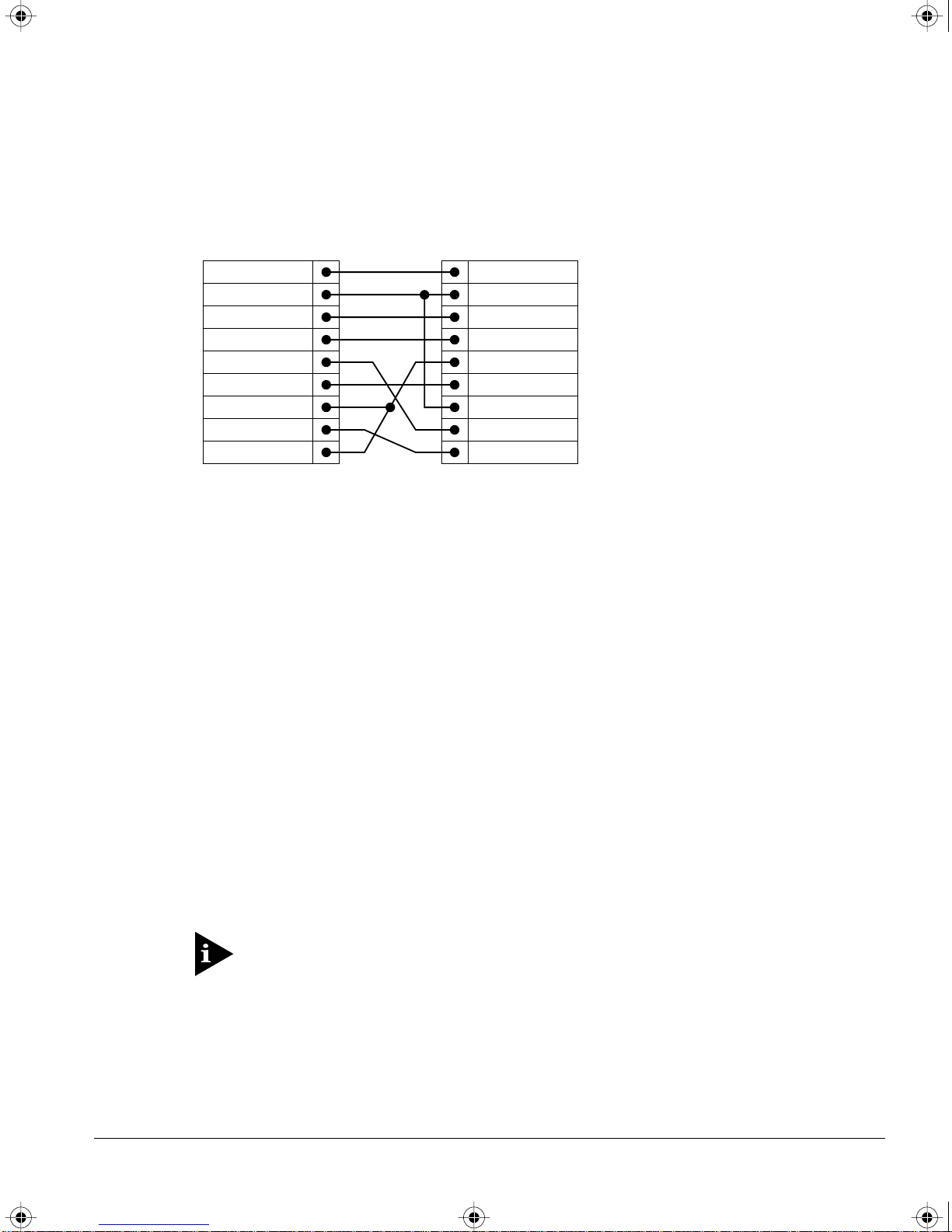
Figure 2-3 shows the pin-outs for a 9-pin to 9-pin PC-AT null-modem serial cable.
P
OWERING-UP THE SWITCH
Summit
Cable connector: 9-pin female
Screen
DTR
TxD
RxD
CTS
Ground
DSR
RTS
DCD
Shell
4
3
2
8
5
6
7
1
PC-AT Serial Port
Cable connector: 9-pin female
1
2
3
4
5
6
7
8
Screen
DCD
RxD
TxD
DTR
Ground
DSR
RTS
CTS
Shell
Figure 2-3: PC-AT serial null-modem cable pin-outs
POWERING-UP THE SWITCH
To turn on power to the Switch, connect the power cable to the Switch and then to the
wall outlet, and turn the on/off switch to the on position.
CHECKING THE INSTALLATION
After turning on power to the Summit, the device performs a Power On Self-Test
(POST).
During the POST, all ports are temporarily disabled, the packet LED is off, the power
LED is on, and the MGMT LED ßashes. The MGMT LED ßashes until the Switch has
successfully passed the POST.
If the Switch passes the POST, the MGMT LED blinks at a slow rate (1 blink per
second). If the Switch fails the POST, the MGMT LED shows a solid yellow light.
For more information on the LEDs, refer to Table 1-2 and Table 1-4.
SUMMIT SWITCH INSTALLATION AND USER GUIDE 2-5
SUMMIT.BK Page 6 Thursday, September 25, 1997 12:33 PM
I
NSTALLATION AND SETUP
LOGGING IN FOR THE FIRST TIME
After the Summit has completed the POST, it is operational. Once operational, you can
log in to the Switch and conÞgure an IP address for the default VLAN (named default).
To manually conÞgure the IP settings, perform the following steps:
1 Connect a terminal or workstation running terminal-emulation software to the
console port.
2 At your terminal, press [Return] one or more times until you see the login prompt.
3 At the login prompt, enter the default user name admin to log on with administrator
privileges. For example:
login: admin
Administrator capabilities allow you to access all Switch functions.
For more information on Switch secur ity, refer to Chapter 3.
4 At the password prompt, press [Return].
The default name, admin, has no password assigned. When you have successfully
logged on to the Switch, the command-line prompt displays the name of the Switch
in its prompt.
5 Assign an IP address and subnetwork mask for VLAN default by typing
config vlan default ipaddress 123.45.67.8 255.255.255.0
Your changes take effect immediately.
6 Save your conÞguration changes so that they will be in effect after the next Switch
reboot, by typing
save
For more information on saving configuration changes, refer to Chapter 11.
7 When you are Þnished using the facility, logout of the Switch by typing
logout
After two incorrect login attempts, the Summit locks you out of the login facility.
You must wait a few minutes before attempting to log in again.
2-6 SUMMIT SWITCH INSTALLATION AND USER GUIDE

SUMMIT.BK Page 1 Thursday, September 25, 1997 12:33 PM
3
Accessing The Switch
This chapter provides the following required information to begin managing the
Summit:
¥ ConÞguring the Switch for management
¥ Switch management methods
¥ ConÞguring SNMP
¥ ConÞguring Switch ports
In order for configuration changes to be retained through a Switch power cycle
or reboot, you must issue a SAVE command after you have made the change.
For more information on the SAVE command, refer to Chapter 11.
CONFIGURING MANAGEMENT ACCESS
The Summit supports the following two level levels of management:
¥ User
¥ Administrator
A user-level account has viewing access to all manageable parameters, with the
exception of the following:
¥ User account database
¥ SNMP community strings
SUMMIT SWITCH INSTALLATION AND USER GUIDE 3-1

SUMMIT.BK Page 2 Thursday, September 25, 1997 12:33 PM
A
CCESSING THE SWITCH
A user-level account can use the ping command to test device reachability, and change
the password assigned to the account name. If you have logged on with user
capabilities, the command-line prompt will end with a (>) sign. For example:
Summit1:2>
An administrator-level account can view and change all Switch parameters. It can also
add and delete users, and change the password associated with any account name. The
administrator can disconnect a management session that has been established by way of
a Telnet connection. If this happens, the user logged on by way of the Telnet connection
is notiÞed that the session has been terminated.
If you have logged on with administrator capabilities, the command-line prompt will
end with a (#) sign. For example:
Summit1:18#
The prompt text is taken from the SNMP sysname setting. The number that follows the
colon indicates the sequential line/command number.
If an asterisk (*) appears in front of the command-line prompt, it indicates that you
have outstanding conÞguration changes that have not been saved. For example:
*Summit1:19#
For more information on saving configuration changes, refer to Chapter 11.
DEFAULT ACCOUNTS
By default, the Switch is conÞgured with two accounts, as shown in Table 3-1.
Table 3-1: Default Accounts
Account Name Access Level
admin This user can access and change all manageable
parameters. The admin account cannot be deleted.
user This user can view (but not change) all manageable
parameters, with the following exceptions:
■ This user cannot view the user account database.
■ This user cannot view the SNMP community strings.
This user has access to the ping command.
3-2 SUMMIT SWITCH INSTALLATION AND USER GUIDE

SUMMIT.BK Page 3 Thursday, September 25, 1997 12:33 PM
CHANGING THE DEFAULT PASSWORD
Default accounts do not have passwords assigned to them. Passwords must have a
minimum of 4 characters and can have a maximum of 12 characters.
Passwords are case-sensitive.
To add a password to the default admin account, follow these steps:
1 Log in to the Switch using the name admin.
2 At the password prompt, press [Return].
3 Add a default admin password by typing the following:
config account admin
C
ONFIGURING MANAGEMENT ACCESS
4 Enter the new password at the prompt.
5 Re-enter the new password at the prompt.
To add a password to the default user account, follow these steps:
1 Log in to the Switch using the name admin.
2 At the password prompt, press [Return].
3 Add a default user password by typing the following:
config account user
4 Enter the new password at the prompt.
5 Re-enter the new password at the prompt.
If you forget your password while logged out of the command-line interface,
contact your local technical support representative, who will advise on your next
course of action.
CREATING A MANAGEMENT ACCOUNT
The Switch can have a total of three management accounts. You can use the default
names (admin and user), or you can create new names and passwords for the accounts.
Passwords must have a minimum of 4 characters and can have a maximum of 12
characters.
The account name “admin” cannot be deleted.
SUMMIT SWITCH INSTALLATION AND USER GUIDE 3-3

SUMMIT.BK Page 4 Thursday, September 25, 1997 12:33 PM
A
CCESSING THE SWITCH
To create a new account, follow these steps:
1 Log in to the Switch as admin.
2 At the password prompt, press [Return].
3 Add a new user by using the following command:
create account [admin | user] <username>
4 Enter the password at the prompt.
5 Re-enter the password at the prompt.
VIEWING SWITCH ACCOUNTS
To view the accounts that have been created, you must have administrator privileges.
Enter the following to see the accounts:
show account
Output from the show accounts command is as follows:
#show accounts
User Name Access LoginOK Failed Session
------------- ------ ------- ------ ------- admin R/W 0 0
user RO 0 0
DELETING A SWITCH ACCOUNT
To delete a Switch account, you must have administrator privileges. Use the following
command to delete an account:
delete account <username>
METHODS OF MANAGING THE SUMMIT
You can manage the Summit using the following methods:
¥ Access the command-line interface by connecting a terminal (or workstation with
terminal-emulation software) to the Summit console port.
¥ Access the command-line interface over a TCP/IP network using a Telnet
connection.
3-4 SUMMIT SWITCH INSTALLATION AND USER GUIDE
 Loading...