

Extreme Networks BlackDiamond 8800 Series, BlackDiamond 10808, BlackDiamond 12800 Series, Summit Family Hardware Installation Manual

Extreme Networks Consolidated ExtremeXOS
Hardware Installation Guide
BlackDiamond 8800 Series Switches
BlackDiamond 12800 Series Switches
BlackDiamond 10808 Switch
Summit Family Switches
Extreme Networks, Inc.
3585 Monroe Street
Santa Clara, California 95051
(888) 257-3000
(408) 579-2800
http://www.extremenetworks.com
Published: 2007
Part number: 100172-00 Rev. 07

AccessAdapt, Alpine, BlackDiamond, ESRP, Ethernet Everywhere, Extreme Enabled, Extreme Ethernet Everywhere,
Extreme Networks, Extreme Standby Router Protocol, Extreme Turbodrive, Extreme Velocity, ExtremeWare,
ExtremeWorks, ExtremeXOS, the Go Purple Extreme Solution, Sentriant, ServiceWatch, ScreenPlay, Summit,
SummitStack, Unified Access Architecture, Unified Access RF Manager, UniStack, Universal Port, the Extreme
Networks logo, the Alpine logo, the BlackDiamond logo, the Extreme Turbodrive logo, the Summit logos, the
Powered by ExtremeXOS logo, and the Color Purple, among others, are trademarks or registered trademarks of
Extreme Networks, Inc. or its subsidiaries in the United States and/or other countries.
© 2006–2007 Extreme Networks, Inc. All Rights Reserved.
Specifications are subject to change without notice.
All other registered trademarks, trademarks and service marks are property of their respective owners.
For safety compliance information, see Appendix A, “Safety Information.”
2
Extreme Networks Consolidated ExtremeXOS Hardware Installation Guide

Table of Contents
Preface......................................................................................................................................... 15
Introduction .............................................................................................................................15
Conventions..............................................................................................................................16
Related Publications .................................................................................................................16
Part 1: Site Preparation
Chapter 1: Site Preparation............................................................................................................ 21
Planning Your Site ....................................................................................................................22
Meeting Site Requirements ..................................................................................................22
Evaluating and Meeting Cable Requirements..........................................................................22
Meeting Power Requirements ...............................................................................................22
Meeting Site Requirements ........................................................................................................22
Operating Environment Requirements ...................................................................................23
Building and Electrical Codes.........................................................................................23
Wiring Closet Considerations ..........................................................................................24
Temperature .................................................................................................................24
BlackDiamond Family Chassis Spacing Requirements.......................................................25
Summit Family of Switches Spacing Requirements...........................................................25
BlackDiamond Family Chassis Airflow Requirements ........................................................25
Electrostatic Discharge ..................................................................................................27
Humidity ......................................................................................................................27
Rack Specifications and Recommendations ...........................................................................27
Mechanical Recommendations for the Rack .....................................................................28
Protective Grounding for the Rack...................................................................................28
Space Requirements for the Rack ...................................................................................29
Securing the Rack .........................................................................................................29
Evaluating and Meeting Cable Requirements ...............................................................................30
Cabling Standards ...............................................................................................................30
Cable Labeling and Record Keeping......................................................................................30
Installing Cable...................................................................................................................31
Fiber Optic Cable ..........................................................................................................33
Cable Distances ............................................................................................................33
RJ-45 Connector Jackets .....................................................................................................34
Radio Frequency Interference...............................................................................................35
Making Network Interface Cable Connections.........................................................................35
Meeting Power Requirements .....................................................................................................36
LAN Systems ......................................................................................................................36
Power Supply Requirements.................................................................................................36
PoE Devices .......................................................................................................................37
AC Power Cable Requirements..............................................................................................37
Replacing the Power Cable.............................................................................................37
Uninterruptible Power Supply Requirements ..........................................................................37
UPS Features................................................................................................................38
Selecting a UPS............................................................................................................38
Extreme Networks Consolidated ExtremeXOS Hardware Installation Guide
3

Table of Contents
Calculating Amperage Requirements ...............................................................................38
UPS Transition Time .....................................................................................................38
Applicable Industry Standards....................................................................................................39
Part 2: BlackDiamond Switches
Chapter 2: Overview of the BlackDiamond Switches ........................................................................ 43
Supported Features ...................................................................................................................43
Full-Duplex Support ..................................................................................................................44
Management Ports ....................................................................................................................44
External Compact Flash Memory Card .........................................................................................44
BlackDiamond 8806 Switch Chassis...........................................................................................44
BlackDiamond 8810 Switch Chassis...........................................................................................46
BlackDiamond 12804 Switch Chassis.........................................................................................47
BlackDiamond 12802 Switch Chassis.........................................................................................49
BlackDiamond 10808 Switch.....................................................................................................50
Chapter 3: BlackDiamond 8800 Modules........................................................................................ 53
Management Switch Modules (MSM) ..........................................................................................53
Slots for BlackDiamond 8800 MSMs ....................................................................................53
MSM Activity ......................................................................................................................54
MSM-G8X and MSM-48 Modules..........................................................................................54
MSM LEDs .........................................................................................................................56
I/O Modules..............................................................................................................................56
BlackDiamond 8800 Original Series I/O Modules ...................................................................57
G24X I/O Module ..........................................................................................................57
10G4X I/O Module ........................................................................................................58
G48T I/O Module ..........................................................................................................59
G48P I/O Module ..........................................................................................................59
BlackDiamond 8800 A-Series I/O Modules ............................................................................61
G48Ta I/O Module.........................................................................................................61
G48Xa I/O Module.........................................................................................................62
10G4Xa I/O Module.......................................................................................................63
10G4Ca I/O Module.......................................................................................................63
BlackDiamond 8800 E-Series I/O Modules ............................................................................64
G48Te I/O Module.........................................................................................................64
G48Pe I/O Module.........................................................................................................65
I/O Module LEDs.................................................................................................................66
Module LEDs ................................................................................................................66
Port LEDs on Non-PoE Modules......................................................................................66
Port LEDs on PoE Modules (G48P and G48Pe) ................................................................67
Chapter 4: BlackDiamond 12800 Series Modules ........................................................................... 69
About BlackDiamond 12800 Series Modules ...............................................................................69
BlackDiamond 12800 Series MSMs............................................................................................70
Redundant MSM Activity .....................................................................................................71
MSM LEDs .........................................................................................................................71
MSM-5 and MSM-5R Modules .............................................................................................72
BlackDiamond 12800 Series I/O Modules ...................................................................................73
I/O Module LEDs.................................................................................................................73
4
Extreme Networks Consolidated ExtremeXOS Hardware Installation Guide

Table of Contents
I/O Port LEDs......................................................................................................................74
GM-20T I/O Module ............................................................................................................74
GM-20T LEDs...............................................................................................................75
GM-20XT and GM-20XTR I/O Modules ..................................................................................75
GM-20XT and GM-20XTR LEDs ......................................................................................76
XM-2X and XM-2XR I/O Modules ..........................................................................................76
XM-2X and XM-2XR LEDs ..............................................................................................77
Distinguishing a BlackDiamond 12800 Series MSM from an I/O Module ........................................77
Module Slot Assignments...........................................................................................................77
Chapter 5: BlackDiamond 10808 Series Modules ........................................................................... 79
About the BlackDiamond 10808 MSMs ......................................................................................79
MSM Activity ......................................................................................................................80
MSM LEDs .........................................................................................................................81
About the BlackDiamond 10808 I/O Modules ..............................................................................82
G60T Module .....................................................................................................................83
G60T LEDs...................................................................................................................83
G60X Module .....................................................................................................................84
Mini-GBIC Ports ............................................................................................................84
G60X LEDs...................................................................................................................85
G20X Module .....................................................................................................................85
Mini-GBIC Ports ............................................................................................................86
G20X LEDs...................................................................................................................86
10G6X Module ...................................................................................................................86
XENPAK Ports ..............................................................................................................87
10G6X LEDs.................................................................................................................87
10G2X Module ...................................................................................................................88
XENPAK Ports ..............................................................................................................88
10G2X LEDs.................................................................................................................89
10G2H Module ...................................................................................................................89
XENPAK Ports ..............................................................................................................90
Mini-GBIC Ports ............................................................................................................90
10G2H LEDs ................................................................................................................90
I/O Module LEDs.................................................................................................................91
Part 3: Installing BlackDiamond Switches and Modules
Chapter 6: Installing the BlackDiamond 8810 Chassis..................................................................... 95
Safety Information ....................................................................................................................95
Unpacking the BlackDiamond 8810 Chassis................................................................................96
Pre-Installation Requirements ....................................................................................................99
Attaching the BlackDiamond 8810 Mid-Mount Rack Brackets.....................................................100
Rack Mounting the BlackDiamond 8810 Chassis .......................................................................101
Grounding the BlackDiamond 8810 Chassis ..............................................................................103
Initial Management Access ......................................................................................................104
Chapter 7: Installing the BlackDiamond 8806 and BlackDiamond 12804 Chassis........................... 105
Unpacking the BlackDiamond 8806/12804 Chassis...................................................................106
Pre-installation Requirements ..................................................................................................109
Attaching the BlackDiamond 8806/12804 Mid-Mount Brackets ..................................................109
Extreme Networks Consolidated ExtremeXOS Hardware Installation Guide
5

Table of Contents
Rack-Mounting the BlackDiamond 8806/12804 Chassis ............................................................110
Grounding the BlackDiamond 8806/12804 Chassis ...................................................................112
Initial Management Access ......................................................................................................113
Chapter 8: Installing the BlackDiamond 12802 Chassis................................................................. 115
Unpacking the BlackDiamond 12802 Chassis............................................................................115
Rack-Mounting the BlackDiamond 12802 Chassis .....................................................................117
Required Tools and Equipment...........................................................................................117
Front-Mounting a BlackDiamond 12802 Chassis..................................................................117
Mid-Mounting a BlackDiamond 12802 Chassis....................................................................118
Grounding the BlackDiamond 12802 Chassis ............................................................................119
Initial Management Access ......................................................................................................120
Chapter 9: Installing a BlackDiamond 10808 Chassis ................................................................... 121
Safety Information ..................................................................................................................121
Required Tools and Resources..................................................................................................122
Unpacking the Chassis and Preparing the Rack..........................................................................122
Checking the Shipping Status Indicators .............................................................................122
Removing the Accessories Box............................................................................................124
Removing the Carton from the Chassis ................................................................................126
Installing the Chassis ..............................................................................................................128
Standard Rack Installation .................................................................................................129
Mid-Mount Rack Installation ..............................................................................................132
Grounding the BlackDiamond 10808 Chassis ............................................................................134
Initial Management Access ......................................................................................................136
Chapter 10: Extreme Networks Power Supply Units for BlackDiamond Switches.............................. 137
Safety ....................................................................................................................................137
BlackDiamond PSU Compatibility .............................................................................................138
Extreme Networks 1200 W DC PSU ..........................................................................................139
Minimum Software Required ..............................................................................................139
Pre-Installation Requirements ............................................................................................140
Installing the DC Wiring .....................................................................................................140
Installing an Extreme Networks 1200 W DC PSU .................................................................141
Removing an Extreme Networks 1200 W DC PSU.................................................................144
Front Panel LEDs ........................................................................................................145
Extreme Networks 700/1200 W AC PSU ...................................................................................146
Pre-Installation Requirements ............................................................................................146
Installing an Extreme Networks 700/1200 W AC PSU...........................................................147
Removing an Extreme Networks 700/1200 W AC PSU..........................................................149
Front Panel LEDs ..............................................................................................................150
Power Supply Cords.....................................................................................................150
Fuse ..........................................................................................................................151
Specifications...................................................................................................................151
Extreme Networks 600/900 W AC PSU .....................................................................................152
Minimum Software Required ..............................................................................................153
Pre-Installation Requirements ............................................................................................153
Installing an Extreme Networks 600/900 W AC PSU.............................................................154
Removing or Replacing an Extreme Networks 600/900 W AC PSU.........................................155
6
Extreme Networks Consolidated ExtremeXOS Hardware Installation Guide

Table of Contents
Front Panel LEDs ..............................................................................................................156
Power Supply Cords...........................................................................................................156
Fuse ................................................................................................................................157
Specifications...................................................................................................................157
Extreme Networks 325 W DC Power Supply...............................................................................158
Minimum Software Required ..............................................................................................158
Pre-Installation Requirements ............................................................................................159
Installing the DC Wiring .....................................................................................................159
Installing an Extreme Networks 325 W DC PSU ...................................................................160
Removing an Extreme Networks 325 W DC PSU...................................................................163
LEDs................................................................................................................................164
Fuse ................................................................................................................................164
Specifications...................................................................................................................164
Extreme Networks 325 W AC Power Supply ...............................................................................165
Pre-Installation Requirements ............................................................................................165
Installing an Extreme Networks 325 W AC PSU ...................................................................166
Installing Retaining Brackets and Connecting Power.............................................................168
Removing an Extreme Networks 325 W AC PSU...................................................................170
Front Panel LEDs ..............................................................................................................170
Power Supply Cords...........................................................................................................171
Fuse ................................................................................................................................171
Specifications.........................................................................................................................171
Chapter 11: Installing BlackDiamond Series Modules.................................................................... 173
Module Slot Assignments.........................................................................................................173
Distinguishing a BlackDiamond 8800 or 12800 MSM from an I/O Module ...................................174
Installing a BlackDiamond 8800 or 12800 Series Module ..........................................................175
Connecting and Disconnecting Cables on the 10G4Ca Module.....................................................178
Installing a BlackDiamond 10808 Series Module .......................................................................179
Installing a Backup MSM.........................................................................................................182
Verifying the Module Installation ..............................................................................................182
Displaying Slot Status Information ......................................................................................182
Removing a BlackDiamond 8800 or 12800 Series Module .........................................................183
Removing a BlackDiamond 10808 Series Module ......................................................................184
BlackDiamond Series Blank Front Panels ..................................................................................185
Installing a Blank Front Panel ............................................................................................185
Removing a Blank Front Panel............................................................................................186
Installing or Removing an External Compact Flash Memory Card............................................188
Part 4: Installing BlackDiamond Switch Accessories
Chapter 12: BlackDiamond AC Power Cord Retaining Brackets ...................................................... 191
BlackDiamond 8810 AC Power Cord Retaining Bracket ..............................................................191
Installing the BlackDiamond 8810 AC Power Cord Retaining Bracket.....................................191
Disconnecting a BlackDiamond 8810 AC Power Cord ...........................................................193
BlackDiamond 8806/12804 AC Power Cord Retainer Channel ....................................................194
Pre-Installation Requirements ............................................................................................194
Installing the BlackDiamond 8806/12804 AC Power Cord Retainer Channel...........................194
Removing the BlackDiamond 8806/12804 AC Power Cord Retainer Channel ..........................196
Extreme Networks Consolidated ExtremeXOS Hardware Installation Guide
7

Table of Contents
Chapter 13: BlackDiamond Cable Management ............................................................................. 197
About BlackDiamond Cable Management ..................................................................................197
Installing the BlackDiamond 10808 Cable Manager ...................................................................197
Using the Cable Holders and Cable Clips...................................................................................202
Connecting Cable Holders ..................................................................................................203
Connecting Cable Clips ......................................................................................................204
Part 5: BlackDiamond Maintenance Procedures
Chapter 14: Replacing the BlackDiamond 12802 PSU/Fan Controller and Fan Tray......................... 209
Safety Information ..................................................................................................................209
Pre-installation Requirements ..................................................................................................209
Replacing the BlackDiamond 12802 Fan Tray ...........................................................................209
Replacing a BlackDiamond PSU/Fan Controller ..........................................................................211
Chapter 15: Replacing a BlackDiamond 8800 Series/BlackDiamond 12804 PSU/Fan Controller ...... 213
Pre-Installation Requirements ..................................................................................................213
Removing a BlackDiamond 8800/12804 PSU/Fan Controller ......................................................213
Installing a BlackDiamond 8800/12804 Spare PSU/Fan Controller..............................................216
Chapter 16: Replacing a BlackDiamond 12804 or 8800 Series Fan Tray........................................ 217
Pre-Installation Requirements ..................................................................................................217
Removing the Fan Tray ............................................................................................................217
Installing the BlackDiamond 8810 Spare Fan Tray.....................................................................219
Chapter 17: Replacing the BlackDiamond 10808 Switch Fan Tray, Air Filter, and
Power Supply Controller .............................................................................................................. 221
Replacing a BlackDiamond 10808 Switch Fan Tray ...................................................................221
Removing the Fan Tray ......................................................................................................221
Installing the Replacement Fan Tray ...................................................................................222
Replacing the BlackDiamond 10808 Air Filter ...........................................................................223
Replacing the BlackDiamond 10808 Power Supply Controller .....................................................224
Pre-Installation Requirements ............................................................................................225
Removing a Power Supply Controller ...................................................................................225
Installing a Power Supply Controller ....................................................................................226
Verifying a Successful Installation.......................................................................................226
Chapter 18: Repacking a BlackDiamond Chassis........................................................................... 227
Safety Information ..................................................................................................................227
Repacking the BlackDiamond 8810 Chassis ..............................................................................228
Repacking the BlackDiamond 8806/12804 Chassis ...................................................................231
Repacking the BlackDiamond 12802 Chassis ............................................................................234
Repacking the BlackDiamond 10808 Chassis ............................................................................235
8
Extreme Networks Consolidated ExtremeXOS Hardware Installation Guide

Table of Contents
Part 6: Summit Family of Switches
Chapter 19: Summit Family of Switches........................................................................................ 241
Overview of the Summit Switches .............................................................................................241
Summit X250e Series Switches................................................................................................242
Summit X250e-24t Switch ................................................................................................242
Summit X250e-24t Switch Front Panel .........................................................................242
Summit X250e-24t Switch Rear Panel ..........................................................................243
Summit X250e-24p Switch................................................................................................244
Summit X250e-24p Switch Front Panel ........................................................................244
Summit X250e-24p Switch Rear Panel .........................................................................245
Summit X250e-48t Switch ................................................................................................245
Summit X250e-48t Switch Front Panel .........................................................................246
Summit X250e-48t Switch Rear Panel ..........................................................................246
Summit X250e-48p Switch................................................................................................247
Summit X250e-48p Switch Front Panel ........................................................................248
Summit X250e-48p Switch Rear Panel .........................................................................248
Summit X250e-48p Power Supplies..............................................................................249
Internal Power Supply............................................................................................249
External Power Supplies.........................................................................................249
Summit X250e Series Switch LEDs ..........................................................................................250
Summit X450 Series Switches .................................................................................................252
Summit X450-24t Switch ..................................................................................................252
Summit X450-24t Switch Front Panel...........................................................................252
Summit X450-24t Switch Rear Panel............................................................................253
Summit X450-24x Switch..................................................................................................254
Summit X450-24x Switch Front Panel ..........................................................................254
Summit X450-24x Switch Rear Panel ...........................................................................255
Summit X450a Series Switches................................................................................................256
Summit X450a-24t Switch ................................................................................................256
Summit X450a-24t Switch Front Panel .........................................................................257
Summit X450a-24t Switch Rear Panel ..........................................................................257
Summit X450a-24tDC Switch ............................................................................................259
Summit X450a-24tDC Switch Front Panel.....................................................................259
Summit X450a-24tDC Switch Rear Panel......................................................................260
Summit X450a-24x Switch ................................................................................................261
Summit X450a-24x Switch Front Panel.........................................................................261
Summit X450a-24x Switch Rear Panel..........................................................................262
Summit X450a-24xDC Switch ............................................................................................263
Summit X450a-24xDC Switch Front Panel.....................................................................264
Summit X450a-24xDC Switch Rear Panel .....................................................................264
Summit X450a-48t Switch ................................................................................................265
Summit X450a-48t Switch Front Panel .........................................................................266
Summit X450a-48t Switch Rear Panel ..........................................................................266
Summit X450a-48tDC Switch ............................................................................................267
Summit X450a-48tDC Switch Front Panel.....................................................................268
Summit X450a-48tDC Switch Rear Panel......................................................................269
Summit X450e Series Switches................................................................................................270
Summit X450e-24p Switch................................................................................................270
Summit X450e-24p Switch Front Panel ........................................................................271
Summit X450e-24p Switch Rear Panel .........................................................................271
Extreme Networks Consolidated ExtremeXOS Hardware Installation Guide
9

Table of Contents
Summit X450e-48p Switch................................................................................................272
Summit X450e-48p Switch Front Panel ........................................................................273
Summit X450e-48p Switch Rear Panel .........................................................................274
Summit X450e-48p Power Supplies..............................................................................275
Internal PSU.........................................................................................................275
External PSUs.......................................................................................................275
Summit X450, X450a, and X450e Series Switch LEDs...............................................................276
Chapter 20: Installing Summit Family Switches............................................................................. 279
Safety Information ..................................................................................................................279
Building a SummitStack Configuration ......................................................................................280
Slot Numbers ...................................................................................................................280
About Redundancy ............................................................................................................281
Placing Summit Family Switches for Stacked Operation........................................................281
Connecting the Switches to Form the Stack Ring..................................................................281
Connecting a Stacking Cable to a Stacking Port ...................................................................283
Connecting the Console Port...............................................................................................284
Management Port Cabling ..................................................................................................284
Stacking Port LEDs ...........................................................................................................284
Installing a Summit Family Switch............................................................................................285
Rack-Mounting a Summit Switch........................................................................................285
Free-Standing and Desktop Mounting of Multiple Switches ...................................................286
Removing a Summit Switch from a Rack (AC units only) .......................................................286
Installing and Removing Summit X450a Series DC-Powered Switches..........................................286
Connecting the Internal DC Power Supply to the DC Source Voltage .......................................287
Grounding the Summit X450a-48tDC Switch .................................................................287
Connecting the DC Wiring Harness to the DC Source Voltage ...........................................288
Attaching the DC Wiring Harness to the DC Power Socket on the Switch...........................290
Removing a Summit X450a-48tDC Switch from a Rack ........................................................291
Initial Management Access ......................................................................................................292
Chapter 21: Summit Option Cards.................................................................................................293
Overview ................................................................................................................................293
Safety Information ..................................................................................................................294
XFP and XENPAK Safety Specifications.........................................................................294
Summit XGM-2xn Option Card..................................................................................................295
Mixing ZR XENPAKs with Other Types.................................................................................295
Installing the Summit XGM-2xn Option Card........................................................................296
Summit XGM2-2xn Option Card................................................................................................297
Installing the Summit XGM2-2xn Option Card......................................................................298
Installing or Removing XENPAK Modules...................................................................................300
Installing a XENPAK Module ..............................................................................................300
Removing a XENPAK Module .............................................................................................301
Summit XGM2-2xf Option Card ................................................................................................302
Installing the Summit XGM2-2xf Option Card.......................................................................303
Installing or Removing XFP Modules .........................................................................................304
Installing an XFP Module ...................................................................................................305
Removing an XFP Module ..................................................................................................306
10
Extreme Networks Consolidated ExtremeXOS Hardware Installation Guide

Table of Contents
Chapter 22: Summit External Power Supplies (EPS) ...................................................................... 307
Overview ................................................................................................................................307
Safety ....................................................................................................................................308
EPS-160 External Power Module (with EPS-T) ...........................................................................309
Installing an EPS-160 External Power Module .....................................................................310
Rack Mounting the EPS-T ............................................................................................310
Installing an EPS-160 into an EPS-T ............................................................................311
Connecting the EPS-160 .............................................................................................311
Removing an EPS-160 from an EPS-T.................................................................................312
EPS-LD External Power Supply Unit..........................................................................................313
Installing an EPS-LD .........................................................................................................313
Rack-mounting the EPS-LD..........................................................................................313
Connecting the EPS-LD to the Switch............................................................................314
Connecting the EPS-LD to Power ..................................................................................316
Removing an EPS-LD ........................................................................................................316
EPS-500 External Power Supply Unit........................................................................................317
Installing and Removing an EPS-500 ..................................................................................318
Rack-mounting an EPS-500 unit ..................................................................................318
Connecting the EPS-500 .............................................................................................319
Removing an EPS-500 unit ..........................................................................................321
EPS-150DC External Power Module (with EPS-T2).....................................................................321
Installing an EPS-T2 .........................................................................................................321
Pre-Installation Requirements ......................................................................................322
Rack Mounting the EPS-T2 ..........................................................................................322
Installing an EPS-150DC ...................................................................................................322
Connecting the DC Wiring Harness to the DC Source Voltage ...........................................323
Installing an EPS-150DC Unit into an EPS-T2 ...............................................................324
Connecting the DC Wiring Harness to the DC Power Socket on the EPS-150DC.................325
Connecting the EPS-150DC to a Switch ........................................................................325
Removing an EPS-150DC ..................................................................................................327
EPS-600LS External Power Module ..........................................................................................328
Power Supply Overview ......................................................................................................328
Single 600-LS Module Configuration: Redundant PoE Power...........................................328
Dual 600-LS Module Configuration: Full Power ..............................................................329
Triple 600-LS Module Configuration: Full Redundant Power............................................329
Internal-to-External PSU Transfer .................................................................................329
Internal PSU failure with single EPS-600LS module.................................................329
Two or Three EPS-600LS modules..........................................................................329
External to Internal PSU Transfer..................................................................................329
Active Internal PSU with single 600-LS module failure .............................................329
Inactive Internal PSU with a dual EPS-600LS configuration and module failure ..........329
Disconnecting the EPS-C/EPS-600LS......................................................................330
Installing an EPS-C Chassis ...............................................................................................330
Pre-Installation Requirements ......................................................................................330
Rack-Mounting the EPS-C............................................................................................330
Installing an EPS-600LS ...................................................................................................332
Removing an EPS-600LS...................................................................................................334
Extreme Networks Consolidated ExtremeXOS Hardware Installation Guide
11

Table of Contents
Part 7: Optics
Chapter 23: Extreme Networks Optics........................................................................................... 337
Safety ....................................................................................................................................337
GBIC, Mini-GBIC, XENPAK, and XFP Regulatory Compliance.................................................338
Mini-GBIC Interfaces...............................................................................................................338
Mini-GBIC Types and Specifications ...................................................................................338
SX mini-GBIC .............................................................................................................338
LX mini-GBIC..............................................................................................................339
ZX mini-GBIC..............................................................................................................341
Dual-speed 100FX/1000LX mini-GBIC ..........................................................................342
100FX mini-GBIC........................................................................................................343
1000BX mini-GBIC .....................................................................................................345
LX100 mini-GBIC........................................................................................................346
Preparing to Install or Replace a Mini-GBIC .........................................................................346
Installing and Removing a Mini-GBIC ..................................................................................347
Connecting Fiber Cables ..............................................................................................348
100FX/1000LX Mini-GBIC .....................................................................................348
LX100 Mini-GBIC..................................................................................................348
XFP Interfaces ........................................................................................................................349
LR XFP Module .................................................................................................................349
SR XFP Module.................................................................................................................350
Installing an XFP Module ...................................................................................................350
Removing an XFP Module ............................................................................................353
XENPAK Interfaces .................................................................................................................354
SR XENPAK .....................................................................................................................354
LR XENPAK......................................................................................................................355
ER XENPAK .....................................................................................................................356
ZR XENPAK......................................................................................................................357
LX4 XENPAK ....................................................................................................................358
LW XENPAK .....................................................................................................................359
Transmitter Clock Locking Mode ...................................................................................360
Installing and Removing a XENPAK Module.........................................................................361
Part 8: Initial Management Access
Chapter 24: Initial Management Access ....................................................................................... 365
Connecting Equipment to the Console Port ................................................................................365
Logging In for the First Time ....................................................................................................367
Part 9: Appendixes
Appendix A: Safety Information .................................................................................................... 371
Considerations Before Installing ...............................................................................................371
Installing Power Supply Units...................................................................................................372
Maintenance Safety.................................................................................................................373
General Safety Precautions ......................................................................................................373
LAN Systems ....................................................................................................................374
PoE Devices .....................................................................................................................374
12
Extreme Networks Consolidated ExtremeXOS Hardware Installation Guide

Table of Contents
Uninterruptible Power Supply Requirements ........................................................................374
UPS Features..............................................................................................................374
Calculating Amperage Requirements .............................................................................375
UPS Transition Time ...................................................................................................375
Power Supply Cords Selection ..................................................................................................375
Battery Replacement and Disposal............................................................................................377
Fiber Optic Ports—Optical Safety .............................................................................................377
GBIC, Mini-GBIC, XENPAK, and XFP Regulatory Compliance...........................................377
Appendix B: Technical Specifications .......................................................................................... 385
BlackDiamond 10808 Switch...................................................................................................385
BlackDiamond 8810 Switch.....................................................................................................388
BlackDiamond 8806/12804 Switch..........................................................................................390
BlackDiamond 12802 Switch...................................................................................................393
Power Supplies for the BlackDiamond Family of Switches ...........................................................395
Summit Family of Switches......................................................................................................398
Summit X250e Series Switches..........................................................................................398
Summit X450 Series Switches ...........................................................................................402
Summit X450a Series Switches..........................................................................................404
Summit X450e Series Switches..........................................................................................408
Summit External Power Supplies ..............................................................................................411
Index .......................................................................................................................................... 415
Extreme Networks Consolidated ExtremeXOS Hardware Installation Guide
13

Table of Contents
14
Extreme Networks Consolidated ExtremeXOS Hardware Installation Guide

WARNING!
NOTE
NOTE
Preface
This preface provides an overview of this guide, describes guide conventions, and lists other
publications that might be useful.
Service to all equipment should be performed by trained and qualified service personnel only. Before installing or
removing any components of the system, or before carrying out any maintenance procedures, you must thoroughly
read the safety information provided in Appendix A of this guide. Failure to follow this safety information can lea d to
personal injury or damage to the equipment.
Introduction
This guide provides the required information to install Extreme Networks® BlackDiamond® 8800 series
switches, BlackDiamond 10808 switches, BlackDiamond
12800 series switches, and the Summit® family
of switches, including the Summit X250e series, Summit X450 series, Summit X450a series, and Summit
X450e series. This guide also contains information about site preparation, switch functionality, and
switch operation.
The Summit X250e series switches, Summit X450 series switches, Summit X450e series switches, and Summit
X450a series switches are called the Summit family of switches when referred to collectively.
This guide is intended for use by network administrators responsible for installing and setting up
network equipment. It assumes a basic working knowledge of:
● Local area networks (LANs)
● Ethernet concepts
● Ethernet switching and bridging concepts
● Routing concepts
● Simple Network Management Protocol (SNMP)
See the ExtremeXOS 12.0 Concepts Guide and the ExtremeXOS 12.0 Command Reference Guide for
information about configuring Extreme Networks BlackDiamond 8800 series switches, BlackDiamond
10808 switches, BlackDiamond 12800 series switches, or Summit family switches.
If the information in the installation note or release note shipped with your Extreme Networks switch differs from the
information in this guide, follow the installation or release note.
Extreme Networks Consolidated ExtremeXOS Hardware Installation Guide
15

Preface
Conventions
Tab le 1 and Ta bl e 2 list conventions used throughout this guide.
Table 1: Notice icons
Icon Notice Type Alerts you to...
Note Important features or instructions.
Caution Risk of personal injury, system damage, or loss of data.
Warning Risk of severe personal injury.
Table 2: Text conventions
Convention Description
Screen displays This typeface represents information as it appears on the screen, or command
The words “enter”
and “type”
[Key] names Key names appear in text in one of two ways:
Words in italicized type Italics emphasize a point of information or denote new terms at the place where
syntax.
When you see the word “enter” in this guide, you must type something, and then
press the Return or Enter key. Do not press the Return or Enter key when an
instruction simply says “type.”
• Referenced by their labels, such as “the Return key” or “the Escape key”
• Written with brackets, such as [Return] or [Esc]
If you must press two or more keys simultaneously, the key names are linked with a
plus sign (+). Example:
Press [Ctrl]+[Alt]+[Del].
they are defined in the text.
Related Publications
The Extreme Networks ExtremeXOS™ switch documentation set includes:
●
ExtremeXOS 12.0 Concepts Guide
●
ExtremeXOS 12.0 Command Reference Guide
●
ExtremeXOS 12.0 Release Notes
Documentation for Extreme Networks products is available from the Extreme Networks website at the
following location:
http://www.extremenetworks.com/services/documentation
16
Extreme Networks Consolidated ExtremeXOS Hardware Installation Guide

Related Publications
You can select and download the following Extreme Networks documentation from the Documentation
Overview page:
● Software User Guides
● Hardware User Guides
You can find archived user guides for software at:
http://www.extremenetworks.com/services/documentation/swuserguides.asp
You can also find archived installation guides for hardware at:
http://www.extremenetworks.com/services/documentation/hwuserguides.asp
Extreme Networks Consolidated ExtremeXOS Hardware Installation Guide
17

Preface
18
Extreme Networks Consolidated ExtremeXOS Hardware Installation Guide

1 Site Preparation


WARNING!
1 Site Preparation
This chapter describes:
● Planning Your Site on page 22
● Meeting Site Requirements on page 22
● Evaluating and Meeting Cable Requirements on page 30
● Meeting Power Requirements on page 36
● Applicable Industry Standards on page 39
The requirements described in this chapter are intended for the system administrator, network
equipment technician, or network manager responsible for installing and managing the network
hardware. It assumes a working knowledge of local area network (LAN) operations, and a familiarity
with communications protocols that are used on interconnected LANs. Installation, maintenance, and
removal of a switch, chassis, or its components must be done by qualified service personnel only.
Qualified service personnel have had appropriate technical training and experience that is necessary to
be aware of the hazards to which they are exposed when performing a task and of measures to
minimize the danger to themselves or other people.
By carefully planning your site, you can maximize the performance of your existing network and ensure
that it is ready to migrate to future networking technologies.
To learn more about safety issues and to ensure safety compliance, see Appendix A.
Service to all equipment should be performed by trained and qualified service personnel only! Before installing or
removing any components of the system, or before carrying out any maintenance procedures, you must read the
safety information provided in Appendix A of this guide.
Extreme Networks Consolidated ExtremeXOS Hardware Installation Guide
21

Site Preparation
Planning Your Site
To install your equipment successfully, you should plan your site carefully. The site planning process
has three major parts:
● Meeting Site Requirements
● Evaluating and Meeting Cable Requirements
● Meeting Power Requirements
Meeting Site Requirements
Your physical installation site must meet the following requirements for a safe and successful
installation:
● Building and electrical code requirements
● Environmental, safety, and thermal requirements for the equipment you plan to install
● Distribution rack requirements
Evaluating and Meeting Cable Requirements
After examining your physical site and ensuring all environment requirements are met, evaluate and
compare your existing cable plant with the requirements of the Extreme Networks equipment to
determine if you need to install new cables (or cabling).
Meeting Power Requirements
To run your equipment safely, you must meet the specific power requirements for each power supply
unit installed in the system.
Meeting Site Requirements
This section addresses the various requirements to consider when preparing your installation site,
including:
● Operating Environment Requirements
● Rack Specifications and Recommendations
22
Extreme Networks Consolidated ExtremeXOS Hardware Installation Guide

Meeting Site Requirements
Operating Environment Requirements
Verify that your site meets all environmental and safety requirements.
Virtually all areas of the United States are regulated by building codes and standards. During the early
planning stages of installing or modifying your LAN, it is important that you develop a thorough
understanding of the regulations that pertain to your location and industry.
Building and Electrical Codes
Building and electrical codes vary depending on your location. Comply with all code specifications
when planning your site and installing cable. The following sections are provided as a resource to
obtain additional information.
Information on major building codes is located at the following websites:
● International Code Council (ICC); 5203 Leesburg Pike; Falls Church, Virginia 22041 USA.
http://www.iccsafe.org
http://www.sbcci.org
Five authorities on electrical codes are:
● National Electrical Code (NEC) Classification (USA only)—a recognized authority on safe electrical
wiring. Federal, state, and local governments use NEC standards to establish their own laws,
ordinances, and codes on wiring specifications. The NEC classification is published by the National
Fire Protection Association (NFPA). The address is NFPA; 1 Batterymarch Park; Quincy,
Massachusetts 02169 USA.
● Underwriters’ Laboratory (UL) (USA only)—an independent research and testing laboratory. UL
http://www.nfpa.org
evaluates the performance and capability of electrical wiring and equipment to determine whether
they meet certain safety standards when properly used. Acceptance is usually indicated by the
words “UL Approved” or “UL Listed.” The address is UL; 333 Pfingsten Road; Northbrook, Illinois
60062-2096 USA.
● National Electrical Manufacturing Association (NEMA) (USA only)—an organization of electrical
http://www.ul.com
product manufacturers. Members develop consensus standards for cables, wiring, and electrical
components. The address is NEMA; 1300 N. 17th Street; Rosslyn, Virginia 22209.
● Electronics Industries Alliance (EIA)—a trade association that develops technical standards,
http://www.nema.org
disseminates marketing data, and maintains contact with government agencies in matters relating to
the electronics industry. The address is EIA; 2500 Wilson Boulevard; Arlington, Virginia 22201 USA.
http://www.eia.org
● Federal Communications Commission (FCC)—a commission that regulates all interstate and foreign
electrical communication systems that originate in the United States according to the
Communications Act of 1934. The FCC regulates all U.S. telephone and cable systems. The address is
FCC; 445 12th Street S.W.; Washington, D.C. 20554 USA.
http://www.fcc.gov
Extreme Networks Consolidated ExtremeXOS Hardware Installation Guide
23

NOTE
NOTE
Site Preparation
Wiring Closet Considerations
Be aware of the following recommendations for your wiring closet:
● Be sure that your system is easily accessible for installation and service. See “Rack Specifications and
Recommendations” on page 27 for information.
● Use appropriate AC power, power distribution, and grounding for your specific installation.
● Use a vinyl floor covering in your wiring closet. (Concrete floors accumulate dust, and carpets can
cause static electricity.)
● Prevent unauthorized access to wiring closets by providing door locks. Install the equipment in a
secured, enclosed, and restricted access location, ensuring that only qualified service personnel have
access to the equipment.
● Provide adequate overhead lighting for easy maintenance.
● Be sure that each wiring closet has a suitable ground. All distribution racks and equipment installed
in the closet should be grounded.
● Be sure that all system environmental requirements are met, such as ambient temperature and
humidity.
Extreme Networks recommends that you consult an electrical contractor for commercial building and wiring
specifications.
Temperature
Extreme Networks equipment generates a significant amount of heat. It is essential that you provide a
temperature-controlled environment for both performance and safety.
Install the equipment only in a temperature- and humidity-controlled indoor area that is free of airborne
materials that can conduct electricity. Too much humidity can cause a fire. Too little humidity can
produce electrical shock and fire.
Follow these general thermal recommendations for your wiring closet:
● Be sure that the ventilation in the wiring closet is adequate to maintain a temperature below 104° F
(40° C).
● Install a reliable air conditioning and ventilation system.
● Keep the ventilation in the wiring closet running during non-business hours; otherwise, the
equipment can overheat.
● Maintain ambient operating temperature: 32° to 104° F (0° to 40° C).
● Maintain storage temperature: -40° to 158° F (-40° to 70° C).
Like all electrical equipment, product lifetimes degrade with increased temperature. If possible, temperatures should
be kept at approximately 78° F (25° C) or lower.
24
Extreme Networks Consolidated ExtremeXOS Hardware Installation Guide

NOTE
Meeting Site Requirements
BlackDiamond Family Chassis Spacing Requirements
Extreme Networks recommends placing no more than three chassis next to each other due to chassis-tochassis heating. The following are some general recommendations for installing your BlackDiamond
10808 switch, BlackDiamond 8800 series of switches, or your BlackDiamond 12804 switch:
● A minimum of one empty 19-inch rack between each set of three adjacent BlackDiamond switches.
or
● Place patch panels between each set of three adjacent BlackDiamond switches. A patch panel does
not require any power and does not generate any heat.
Up to five adjacent switches will continue to function without safety concerns. However, product lifetime may
degrade with continued exposure to high temperatures in close proximity and long term reliability may be
compromised.
Summit Family of Switches Spacing Requirements
Be sure that cables and other equipment do not block the air intake or outflow on an Extreme Networks
Summit family switch. It is best to have at least 3 inches (8 cm) of clear space in front of the air intake
and outflow vents on the sides of the switch; airflow moves from side to side. For proper airflow
through a Summit family switch, leave clear space on the left and right sides of the switch.
Depending on other conditions in the equipment room, it may be possible to install the switches closer
to each other; consult your Extreme Networks Customer Support representative for guidance.
BlackDiamond Family Chassis Airflow Requirements
To ensure proper airflow through a BlackDiamond switch, refer to the following recommendations
when you are installing your switch:
● BlackDiamond 10808 switches require a minimum of 3 inches (8 cm) around both the front and rear
of the chassis from any cabinet wall or other obstruction for proper airflow.
● BlackDiamond 8800 and 12804 switches require a minimum of 1.5 inches (4 cm) around both the left
and right sides of the chassis from any cabinet wall or other obstruction for proper airflow.
● Air temperature measured approximately 1 inch (2.5 cm) from the fan inlet should be less than
104 °F (40 °C).
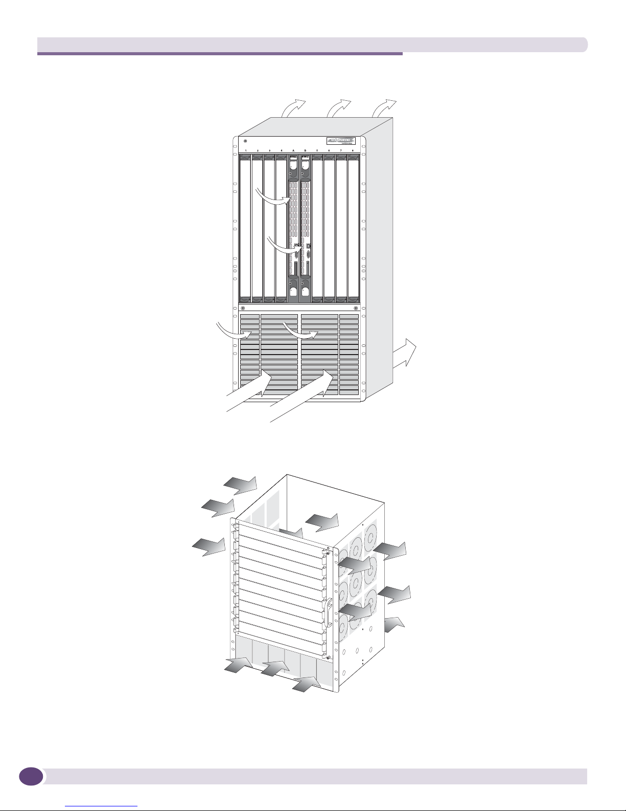
The airflow of the BlackDiamond 10808 switch, BlackDiamond 8800 series of switches, and
BlackDiamond 12804 switch moves through the power supplies and is independent of the airflow
through the modules as shown in Figure 1 and Figure 2.
Extreme Networks Consolidated ExtremeXOS Hardware Installation Guide
25
Site Preparation
Figure 1: Airflow through the BlackDiamond 10808 system chassis
Airflow
through
chassis
Airflow through
power supplies
Figure 2: Airflow through the BlackDiamond 8810 chassis
Airflow at power
supply level
EX_010
Airflow through
fan tray
ASP045
26
Extreme Networks Consolidated ExtremeXOS Hardware Installation Guide
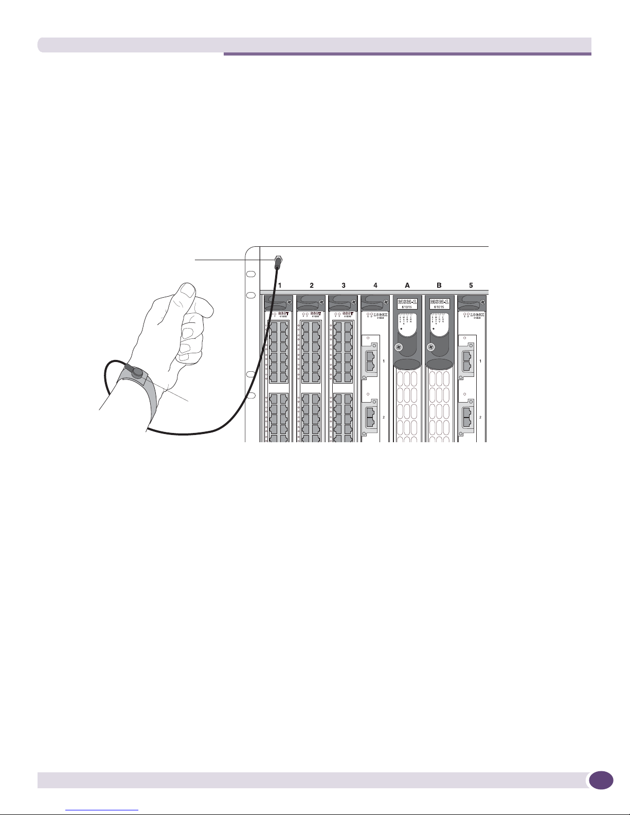
ESD strap
ESD ground
connection
EX_013
Meeting Site Requirements
Electrostatic Discharge
Your system must be protected from static electricity or electrostatic discharge (ESD). Take the following
measures to ensure optimum system performance:
● Remove materials that can cause electrostatic generation (such as synthetic resins) from the wiring
closet. Check the appropriateness of floor mats and flooring.
● Connect metal chassis, conduit, and other metals to ground using dedicated grounding lines.
● Use electrostatically safe equipment and the ESD-preventive wrist strap that is provided with your
equipment. All switches come with ESD-preventive wrist strap connectors and an ESD-preventive
wrist strap as shown in Figure 3.
Figure 3: Using an ESD-preventive wrist strap
Humidity
Operating humidity should be kept between 50 to 70% relative humidity non-condensing during typical
operation and 10% to 95% relative humidity (non-condensing) for short intervals to maximize
equipment life.
Rack Specifications and Recommendations
Racks should conform to conventional standards. In the United States, use EIA Standard RS-310C:
Racks, Panels, and Associated Equipment. In countries other than the United States, use IEC Standard
297. In addition, verify that your rack meets the basic mechanical, space, and earthquake requirements
that are described in this section.
Extreme Networks Consolidated ExtremeXOS Hardware Installation Guide
27

NOTE
Site Preparation
Mechanical Recommendations for the Rack
Use distribution racks that meet the following mechanical recommendations:
● Use an open style, 19-inch rack to facilitate easy maintenance and to provide proper ventilation.
● Use a rack made of steel or aluminum.
● The rack should use the universal mounting rail hole pattern that is identified in IEC Standard 297.
● The rack should have designated earth grounding connections (typically on the base).
● The rack must meet earthquake safety requirements equal to that of the installed chassis.
● The mounting holes should be flush with the rails to accommodate the chassis.
● Install equipment into the lower half of the rack first to avoid making the rack top-heavy.
● The rack should support approximately 600 pounds (272 kilograms).
Protective Grounding for the Rack
Use a rack grounding kit and a ground conductor that is carried back to earth or to another suitable
building ground.
All Extreme Networks switches are designed with mounting brackets that provide solid metal-to-metal
connection to the rack. If you do not use equipment racks, you can attach wiring terminals directly to
the mounting brackets for appropriate grounding. Extreme Networks switches have grounding
terminals that are mounted on the back of the chassis.
At a minimum, follow these guidelines to ground equipment racks to the earth ground:
● CAD weld appropriate wire terminals to building I-beams or earth ground rods.
● Use the appropriate chassis grounding wire for your system, which is dependant upon the available
input current to the power supply.
■ For AC systems using a 20A breaker per PSU (SSI AC), the chassis ground can be as small as
14 AWG. The power cable ground should be the same size as the primary.
■ For DC systems using a 15A breaker per PSU (Summit X450a-48tDC switch), the chassis
ground can be as small as 14 AWG. The power cable ground should be the same size as the
primary.
■ For DC systems using a 40A breaker per PSU (SSI DC), the chassis ground can be as small as
10 AWG. The power cable ground should be the same size as the primary.
This recommendation does not apply to the Summit family of switches, other than the Summit
X450a-48tDC switch. Other Summit switches do not need separate chassis grounding for AC or DC
systems.
For complete details on power supplies and power supply cords, refer to the following: Chapter 6, “Extreme
Networks Power Supply Units for BlackDiamond Switches,” and “Power Supply Cords Selection” on page 375 in
Appendix A, “Safety Information.” Drill and tap wire terminals to equipment racks.
● Position the earth ground as close to the equipment rack as possible to maintain the shortest wiring
distance possible.
● Use a ground impedance tester or micro-ohm meter to test the quality of earth ground connection at
the chassis. This will insure good grounding between the chassis, rack, and earth ground.
28
Extreme Networks Consolidated ExtremeXOS Hardware Installation Guide

NOTE
WARNING!
SPG_007
Secure to floor
with 3/8-inch lag screws or bolts
Meeting Site Requirements
Because building codes vary worldwide, Extreme Networks strongly recommends that you consult an electrical
contractor to ensure proper equipment grounding for your specific installation.
Space Requirements for the Rack
Provide enough space in front of and behind the switch so that you can service it easily. Allow a
minimum of 48 inches (122 cm) in front of the rack and 24 inches (61 cm) behind the rack. When using a
relay rack, provide a minimum of 24 inches (61 cm) of space behind the mounted equipment. Extra
room on each side is optional.
The chassis does not have a switch for turning power to the unit on and off. For systems using an AC power supply,
power to the chassis is disconnected by removing the wall plug from the electrical outlet. For systems using a DC
SSI power supply, power to the chassis can be turned off by lifting the handle on the power supply or by deenergizing the circuit that feeds the power supply, which is usually accomplished by turning off a circuit breaker.
Power to the Summit X450a-24tDC switch and the EPS-150DC can be turned off be disconnecting the DC wiring
harness from the DC power source only, which requires the performance of a qualified, licensed electrician.
Securing the Rack
The rack should be attached to the wiring closet floor with 3/8-inch (9.5 mm) lag screws or equivalent
hardware. The floor under the rack should be level within 3/16-inch (5 mm). Use a floor-leveling
cement compound if necessary or bolt the racks to the floor as shown in Figure 4.
Figure 4: Properly secured rack
Brace open distribution racks if the channel thickness is less than 1/4 inch (6.4 mm).
Extreme Networks Consolidated ExtremeXOS Hardware Installation Guide
29

Site Preparation
Evaluating and Meeting Cable Requirements
This section addresses requirements for the cable you should use when installing your network
equipment. It includes:
● Cabling Standards
● Cable Labeling and Record Keeping
● Installing Cable
● RJ-45 Connector Jackets
● Radio Frequency Interference
Cabling Standards
Extreme Networks recommends using the Building Industry Consulting Service International (BICSI)
Registered Communications Distribution Designer (RCDD), which is globally recognized as a standard
in site planning and cabling. For information, go to:
http://www.bicsi.org
Cable Labeling and Record Keeping
A reliable cable labeling system is essential when planning and installing a network. Maintaining
accurate records helps you to:
● Relocate devices easily.
● Make changes quickly.
● Isolate faults in the distribution system.
● Locate the opposite end of any cable.
● Know the types of network devices that your cabling infrastructure can support.
Consider the following recommendations when setting up a cable labeling system suitable for your
installation:
● Identify cables by securely attaching a label to all cable ends.
● Assign a unique block of sequential numbers to the group of cables that run between each pair of
wiring closets.
● Assign a unique identification number to each distribution rack.
● Identify all wiring closets by labeling the front panel of your Extreme Networks equipment and
other hardware.
● Keep accurate and current cable identification records.
● Post records near each distribution rack. Include the following cable drop information: the cable
source, destination, and jumper location.
30
Extreme Networks Consolidated ExtremeXOS Hardware Installation Guide
 Loading...