

Extreme Networks Summit5i, Summit48si, Alpine 3802, Alpine 3804, Alpine 3808 Hardware Installation Manual
...
Extreme Networks, Inc.
3585 Monroe Street
Santa Clara, California 95051
(888) 257-3000
http://www.extremenetworks.com
Extreme Networks
Consolidated “i” Series
Hardware Installation Guide
Published: August, 2004
Part number: 100093-00 Rev. 07

2
Alpine, Altitude, BlackDiamond, EPICenter, Ethernet Everywhere, Extreme Ethernet Everywhere, Extreme Networks,
Extreme Turbodrive, Extreme Velocity, ExtremeWare, ExtremeWorks, GlobalPx Content Director, the Go Purple Extreme
Solution Partners Logo, ServiceWatch, Summit, the Summit7i Logo, and the Color Purple, among others, are trademarks
or registered trademarks of Extreme Networks, Inc. or its subsidiaries in the United States and other countries. Other
names and marks may be the property of their respective owners.
© 2004 Extreme Networks, Inc. All Rights Reserved.
Specifications are subject to change without notice.
For safety compliance information, see Appendix A.
Authors: Megan Mahar, Julie Laccabue
Production: Megan Mahar, Julie Laccabue

Extreme Networks Consolidated Hardware Guide 3
Contents
Preface
Introduction 11
Conventions 12
Related Publications 13
About This Guide 13
How To Use This Guide 14
Part 1 Common Features
Chapter 1 Summary of Common Switch Features
Software Images 17
Full-Duplex Support 18
Management Ports 18
Mini-GBIC Type and Hardware/Software Support 18
Mini-GBIC Types and Specifications 18
Safety Information 20
Preparing to Install or Replace a Mini-GBIC 20
Installing and Removing a Mini-GBIC 21
GBIC Type and Hardware/Software Support 22
GBIC Media Types and Distances 22
GBIC Specifications 23
Long Range GBIC System Budgets 26
Safety Information 27
Preparing to Install or Replace a GBIC 27
Installing or Replacing a GBIC 28
Part 2 Site Planning

4 Extreme Networks Consolidated Hardware Guide
Chapter 2 Site Preparation
Planning Your Site 34
Step 1: Meeting Site Requirements 34
Step 2: Evaluating and Meeting Cable Requirements 34
Step 3: Meeting Power Requirements 34
Meeting Site Requirements 34
Operating Environment Requirements 34
Rack Specifications and Recommendations 45
Evaluating and Meeting Cable Requirements 47
Cabling Standards 47
Cable Labeling and Record Keeping 48
Installing Cable 48
RJ-45 Connector Jackets 51
Radio Frequency Interference 51
Making Network Interface Cable Connections 52
Meeting Power Requirements 52
Power Supply Requirements 53
AC Power Cable Requirements 53
Uninterruptable Power Supply Requirements 54
Applicable Industry Standards 55
Part 3 Summit Switch
Chapter 3 Summit Switch Overview
Summit Switch Models 59
Summary of Features 60
Summit “i” series switches 60
Memory Requirements 62
Port Connections 62
Following Safety Information 63
Chapter 4 Summit Switch Models
Switch Models 65
Summit1i Switch Front View 66
GBIC Ports 66
LEDs 67
Summit1i Switch Rear View 68
Power Sockets 68
Label 68
Reset Button 68

Extreme Networks Consolidated Hardware Guide 5
Console Port 68
Summit5i Switch Front View 69
GBIC Ports 70
LEDs 71
Summit5i Switch Rear View 71
Power Sockets 71
Label 72
Reset Button 72
Console Port 72
Management Port 72
Summit7i Switch Front View 73
GBIC Ports 74
LEDs 75
Reset Button 75
Console Port 75
Modem Port 76
Management Port 76
PCMCIA Slot 76
Summit7i Switch Rear View 76
Power Sockets 76
Label 77
Summit1i, Summit5i, Summit7i, and Summit48i Switch LEDs 77
Summit48i Switch Front View 78
GBIC Ports 78
LEDs 79
Summit48i Switch Rear View 80
Power Sockets 80
Label 80
Reset Button 80
Console Port 80
Summit48si Switch Front View 81
Mini-GBIC Ports 81
Console Port 82
LEDs 82
Summit48si Switch Rear View 82
Power Supplies 82
Reset Button 83
Summit48si Power Supply LEDs 83
Summit48si Switch Bottom View 84
Labels 84
Summit48si Switch LEDs 85

6 Extreme Networks Consolidated Hardware Guide
Chapter 5 Summit Switch Installation
Mounting the Switch in a Rack 87
Placing the Switch on a Table or Shelf 91
Verifying a Successful Installation 91
Removing and Installing Summit48si AC Power Supplies 91
Installing the AC Power Cable Retaining Bracket 93
Removing the AC Power Cable Retaining Bracket from a Power Cable 94
Installing the Summit48si Switch DC Power Supply 95
Preparing and Attaching the DC Power Supply Cabling 97
Attaching the Connector to the DC Power Supply 98
Removing the Switch from a Rack 98
Part 4 Alpine Switch
Chapter 6 Alpine 3800 Series Switch Overview
Summary of Features 103
Port Connections 104
Switch Components 105
Alpine 3808 Switch 105
Alpine 3804 Switch 105
Alpine 3802 Switch 105
Power Supply 106
Following Safety Information 106
Chapter 7 Alpine 3800 Series Switch Chassis
Alpine 3800 Series Architecture 109
Alpine 3808 Switch Front View 109
Alpine 3808 Switch Rear View 111
Alpine 3804 Switch Front View 111
Alpine 3804 Switch Rear View 113
Alpine 3802 Switch Front View 113
Alpine 3802 Switch Rear View 116
Installing the Chassis 118
Rack Installation 119
Grounding the Alpine 3800 Series Chassis 121
Removing the Chassis 122
Chapter 8 Alpine 3800 Series Switch Power Supplies
Power Supply LEDs 124

Extreme Networks Consolidated Hardware Guide 7
Installing the Alpine 3808 and the Alpine 3804 AC Power Supply 125
Verifying a Successful Installation 127
Removing the Alpine 3808 and the Alpine 3804 AC Power Supply 127
Supplying Power to the Alpine 3802 AC Power Supply 128
Verifying a Successful Installation 129
Installing the Alpine 3808 and the Alpine 3804 DC Power Supply 129
Selecting the Cabling 130
Installing the Power Supply 130
Attaching the Cabling and Supplying Power 133
Verifying a Successful Installation 134
Removing the Alpine 3808 and the Alpine 3804 DC Power Supply 134
Supplying Power to the Alpine 3802 DC Power Supply 135
Selecting the Cabling 136
Attaching the Cabling and Supplying Power 136
Verifying a Successful Installation 137
Installing the Alpine 3800 Series Switch External Power Supply 137
Rack-mounting the EPS-LD unit 139
Connecting the EPS-LD unit 140
Supplying External Power to the FM-32Pi Module 141
Removing an EPS-LD unit 143
Chapter 9 Alpine 3800 Series Switch Management Module
SMMi Memory 146
SMMi LEDs 146
Installing SMMi Modules 147
Verifying the SMMi Module Installation 148
Removing SMMi Modules 148
Chapter 10 Alpine 3800 Series I/O Modules
Configuring I/O Modules 151
GM-4Ti Module 153
GM-4Xi Module 154
GM-4Si Module 157
GM-16X
3
Module 158
GM-16T
3
Module 160
FM-24Ti Module 162
FM-24SFi Module 164
FM-24MFi Module 166
FM-32Ti Module 168
FM-32Pi Module 169
FM-8Vi Module 171
WM-4T1i Module 173

8 Extreme Networks Consolidated Hardware Guide
WM-4E1i Module 174
WM-1T3i Module 175
I/O Module LEDs 175
Installing I/O Modules 178
Verifying the I/O Module Installation 179
LED Indicators 179
Displaying Slot Status Information 179
Installing External Power 180
Removing I/O Modules 180
Chapter 11 Alpine 3800 Series Switch Fan Tray
Alpine 3808 Fan Tray 181
Alpine 3804 Fan Tray 182
Alpine 3802 Fan Tray 182
Removing the Alpine 3808 or Alpine 3804 Fan Tray 183
Installing the Alpine 3808 or Alpine 3804 Fan Tray 184
Part 5 BlackDiamond Switch
Chapter 12 BlackDiamond 6800 Series Switch Overview
Summary of Features 189
Port Connections 190
Switch Components 191
BlackDiamond 6816 Switch 191
BlackDiamond 6808 Switch 191
BlackDiamond 6804 Switch 192
BlackDiamond Power Supplies 192
Switch Connectivity and the Backplane 192
Packet Switching and Routing 193
Following Safety Information 193
Chapter 13 BlackDiamond 6800 Series Switch Chassis
BlackDiamond 6800 Series Architecture 195
BlackDiamond 6816 Switch Front View 195
BlackDiamond 6816 Switch Rear View 197
BlackDiamond 6808 Switch Front View 198
BlackDiamond 6808 Switch Rear View 200
BlackDiamond 6804 Switch Front View 201
BlackDiamond 6804 Switch Rear View 203

Extreme Networks Consolidated Hardware Guide 9
Installing the Chassis 203
Rack Installation 204
Grounding the BlackDiamond 6800 Series Chassis 208
Removing the Chassis 208
Chapter 14 BlackDiamond 6800 Series Switch Power Supplies
220 VAC Power Supplies 212
110 VAC Power Supplies 213
DC Power Supplies 214
Installing a BlackDiamond 6800 Series Power Supply 215
AC Power Cable and Plug 219
Selecting the DC Cabling 220
Preparing the DC Cabling 220
Attaching the DC Cabling 221
Verifying a Successful Installation 222
Removing a BlackDiamond 6800 Series Power Supply 222
Chapter 15 BlackDiamond 6800 Series Management Switch Module
MSM Activity 227
MSM Memory 228
MSM LEDs 229
Installing MSMs 229
Verifying the MSM Module Installation 232
Removing MSMs 233
Chapter 16 BlackDiamond 6800 Series I/O Modules
Configuring I/O Modules 235
10GX
3
Module 236
G8Ti Module 238
G8Xi Module 239
G12SXi Module 241
G16X
3
Module 242
G24T
3
Module 245
F48Ti Module 247
F96Ti Module 248
F32Fi Module 252
P3cSi, P3cMi, P12cSi, and P12cMi Modules 253
ARM 257
MPLS Module 260
A3cSi and A3cMi Modules 263
I/O Module LEDs 267
Installing I/O Modules 268

10 Extreme Networks Consolidated Hardware Guide
Verifying the I/O Module Installation 269
LED Indicators 269
Displaying Slot Status Information 270
Removing I/O Modules 270
Installing XENPAK Modules 271
Chapter 17 BlackDiamond 6800 Series Switch
Fan Tray
BlackDiamond 6816 Fan Trays 273
BlackDiamond 6808 Fan Tray 274
BlackDiamond 6804 Fan Tray 275
Removing a BlackDiamond 6800 Series Fan Tray 276
Installing a BlackDiamond 6800 Series Fan Tray 278
Part 6 Switch Operation
Chapter 18 Initial Switch and Management Access
Connecting Equipment to the Console Port 283
Logging In for the First Time 285
Part 7 Appendixes
Appendix A Safety Information
Important Safety Information 289
Power 289
Power Cable 290
Fuse 290
Connections 291
Lithium Battery 291
Appendix B Switch Technical Specifications
Appendix C Module Technical Specifications
Alpine Modules 302
BlackDiamond Modules 310
Common Module Specifications 319
Index

Extreme Networks Consolidated "i" Series Hardware Installation Guide 11
Preface
This preface provides an overview of this guide, describes guide conventions, and lists other
publications that might be useful.
NOTE
To ensure proper operation of your Extreme Networks equipment, read this guide before you install any
Extreme Networks equipment.
Introduction
This guide provides the required information to install an Extreme Networks® “i” chipset series
Summit
™
switch, Alpine® switch, or BlackDiamond® switch. Installation information is provided for the
“i” chipset series switch models shown in Table 1:
This guide contains information about site location, switch functionality, and switch operation. It is
intended for use by network administrators who are responsible for installing and setting up network
equipment. It assumes a basic working knowledge of:
Table 1: Switch models containing the “i” chipset
Switch Family Switch Model
Summit “i” series • Summit1i
• Summit5i
• Summit7i
• Summit48i
• Summit48si
Alpine 3800 “i”
series
• Alpine 3802
• Alpine 3804
• Alpine 3808
BlackDiamond
6800 “i” series
• BlackDiamond 6804
• BlackDiamond 6808
• BlackDiamond 6816

12 Extreme Networks Consolidated "i" Series Hardware Installation Guide
Preface
• Local Area Networks (LANs)
• Ethernet concepts
• Ethernet switching and bridging concepts
• Routing concepts
• Simple Network Management Protocol (SNMP)
See the ExtremeWare Software User Guide for information about configuring an Extreme Networks switch.
NOTE
If the information in the Release Notes that shipped with your switch differs from the information in this
guide, follow the Release Notes.
Conventions
Table 2 and Table 3 list conventions used throughout this guide.
Table 2: Notice icons
Icon Notice Type Alerts you to...
Note Important features or instructions.
Caution Risk of personal injury, system damage,
or loss of data.
Warning Risk of severe personal injury.
Table 3: Text conventions
Convention Description
Screen displays This typeface represents information as it appears on the screen,
or command syntax.
Screen displays bold This typeface represents commands that you type.
The words “enter”
and “type”
When you see the word “enter” in this guide, you must type
something, and then press the Return or Enter key. Do not press
the Return or Enter key when an instruction simply says “type.”
[Key] names Key names appear in text in one of two ways:
• Referenced by their labels, such as “the Return key” or “the
Escape key”
• Written with brackets, such as [Return] or [Esc]
If you must press two or more keys simultaneously, the key names
are linked with a plus sign (+). Example:
Press [Ctrl]+[Alt]+[Del].

Related Publications
Extreme Networks Consolidated "i" Series Hardware Installation Guide 13
Related Publications
The Extreme Networks switch documentation set includes:
• Extreme Networks Consolidated “i” Series Hardware Installation Guide (this guide)
• ExtremeWare Software User Guide
• ExtremeWare Software Command Reference Guide
• ExtremeWare Release Notes
Documentation for Extreme Networks products is available from the Extreme Networks website at the
following location:
http://www.extremenetworks.com/services/documentation/
You can select and download the following Extreme Networks documentation from the Documentation
section of the Services page:
• Release Notes (you must have a valid service contract to access the release notes)
• Software User Guides
• Hardware User Guides
• White Papers
• Troubleshooting Tools
• Preventative Maintenance
• Instructional Videos
• Archives
About This Guide
This guide describes how to prepare your site and how to install, maintain, and operate your Extreme
Networks switch. It contains information on features that are common to all switches, as well as
switch-specific features. This guide contains seven parts:
• Common Features—Describes features that are shared by the Extreme Networks family of switches.
This section describes software images, full-duplex support, management ports, mini-GBIC and
GBIC modules and their installation.
• Site Planning—Describes how to evaluate, plan, and determine the location of your Extreme
Networks switch.
• Summit Switch—Describes the features that are specific to the Summit switch. This section provides
an overview of the Summit switch, information about model types, summary of features, and
installation guidelines.
Words in italicized type Italics emphasize a point of information or denote new terms at the
place where they are defined in the text.
Table 3: Text conventions (continued)
Convention Description

14 Extreme Networks Consolidated "i" Series Hardware Installation Guide
Preface
• Alpine Switch—Describes the features that are specific to the Alpine switch. This section provides an
overview of the Alpine switch, information about model types, a summary of features, and
installation guidelines.
• BlackDiamond Switch—Describes the features that are specific to the BlackDiamond switch. This
section provides an overview of the BlackDiamond switch, information about model types, a
summary of features, and installation guidelines.
• Switch Operation—Describes how to power on any Extreme Networks switch, verify the switch
installation, connect equipment to the console port, and log in to the switch for the first time.
• Appendixes—Includes information about safety requirements and technical specifications.
How To Use This Guide
Each chapter of this guide contains information on how to successfully operate your Extreme Networks
switch. The Summit-, Alpine-, and BlackDiamond-specific chapters contain information that is
applicable to that family of switch only. All other chapters are applicable to any Extreme Networks “i”
chipset series switch.
Switch-Specific Information
For switch-specific information, be sure to read the applicable switch-specific chapter. For example, if
you have a BlackDiamond switch and you need to remove and replace an I/O module, see “Removing
I/O Modules” in Chapter 16 for details about how to remove and replace an I/O module in a
BlackDiamond chassis.
Common Information
For items applicable to any Extreme Networks switch, make sure you read the appropriate chapter. For
example, to learn how to prepare your site for installing your Extreme Networks equipment, see
Chapter 2, “Site Preparation.”
This guide also contains appendices that describe:
• Switch safety issues
• Switch specifications
• Module specifications
Appendix A, “Safety Information” describes important safety issues such as power, power cables, and
fuses.
Appendix B, “Switch Technical Specifications” is organized according to the family of switch: Summit,
Alpine, and BlackDiamond. This appendix describes switch specifications such as physical dimensions,
weight, certifications, and power supply parameters.
Information that is common to all “i” chipset series switches is described at the end of the appendix.
Appendix C, “Module Technical Specifications” is organized according to the family of switch and
modules available for that switch, and describes module specifications such as physical dimensions,
weight, and standards.
Information that is common to all “i” chipset series modules is described at the end of the appendix.

Part 1
Common Features


Extreme Networks Consolidated "i" Series Hardware Installation Guide 17
1 Summary of Common Switch Features
This chapter describes the features that are shared in common by the Extreme Networks family of
switches. The following topics are described in greater detail:
• Software Images on page 17
• Full-Duplex Support on page 18
• Management Ports on page 18
• Mini-GBIC Type and Hardware/Software Support on page 18
• GBIC Type and Hardware/Software Support on page 22
Software Images
When you receive a new Extreme Networks switch, be aware that an the ExtremeWare® software image
and a BootROM image has been preinstalled at the factory. To verify the software image you are
running on your switch, use the
show version command. The show version command displays the
hardware and software versions currently running on the switch. To ensure that you have the latest
software and BootROM image, go to the support login portion of the Tech Support page at:
http://www.extremenetworks.com/services/
If your switch is running ExtremeWare version 6.2 or later, the Power LED activity is different from
previous versions of ExtremeWare. All other LED activity is the same. See Table 4 for more information
about the Power LED activity on switches running ExtremeWare version 6.2 or later.
NOTE
If the information in the Release Notes that shipped with your switch differs from the information in this
guide, follow the Release Notes.
Table 4: Power LED activity for switches running ExtremeWare version 6.2 or later
LED Color Indicates
Power LED Green
Amber
Off
The indicated power supply unit (PSU) is powered up.
A PSU is installed, but not connected to power.
The PSU is not receiving power or no PSU is present.

18 Extreme Networks Consolidated "i" Series Hardware Installation Guide
Summary of Common Switch Features
Full-Duplex Support
Extreme Networks switches provide full-duplex support for all ports. This means that frames can be
transmitted and received simultaneously, which, in effect, doubles the bandwidth that is available on a
link. Most ports on an Extreme Networks switch autonegotiate for half-duplex or full-duplex operation.
Gigabit Ethernet and 100BASE-FX ports operate in full-duplex mode only in accordance with technical
standards.
Management Ports
The 10/100BASE-TX Ethernet management port allows you to communicate directly to the CPU of the
switch. You can plug an Ethernet cable directly from your laptop into the management port. This
provides you with direct access into the switch and allows you to view and locally manage the switch
configurations.
Do not assign an in-band IP address to the management port VLAN. The management port VLAN is an
out-of-band VLAN, so if it is assigned an in-band IP address (an address where the source and
destination are in the same subnet), the switch will treat it as a normal VLAN and attempt to route
traffic through it.
The management port is located on the following Extreme Networks devices:
• Summit5i—The management port is located on the back side of the switch
• Summit7i—The management port is located on the front side of the switch
• Alpine—Switch Management Module (SMMi) for the Alpine series switch
• BlackDiamond—Management Switch Fabric Module (MSM64i) for the BlackDiamond series switch
Extreme Networks does not recommend that you use the management port to route traffic to any front
panel port on the switch. The management port is designed for switch management purposes.
Mini-GBIC Type and Hardware/Software Support
The Summit48si and Summit series switches, the BlackDiamond G16X3 module, and the Alpine
GM-16X
3
module support the small form pluggable (SFP) GBIC, also known as the mini-GBIC. The
switches and the modules identify the type of mini-GBIC that is installed and verifies that the
mini-GBIC is an Extreme Networks-certified mini-GBIC.
Mini-GBIC Types and Specifications
There are three types of mini-GBIC interfaces:
• SX mini-GBIC, which conforms to the 1000BASE-SX standard
• LX mini-GBIC, which conforms to the 1000BASE-LX standard
• ZX mini-GBIC, which conforms to the IEEE 802.3z standard
Use only Extreme Networks-certified mini-GBICs, available from Extreme Networks, into the
mini-GBIC port in the switch or module.

Mini-GBIC Type and Hardware/Software Support
Extreme Networks Consolidated "i" Series Hardware Installation Guide 19
Table 5 describes the specifications for the SX mini-GBIC interface, Table 6 describes the specifications
for the LX mini-GBIC interface, and Table 7 describes the specifications for the ZX mini-GBIC interface.
Total optical system budget for the SX mini-GBIC is 11.5 dB. Extreme Networks recommends that 3 dB
of the total budget be reserved for losses induced by cable splices/connectors and operating margin.
While 8.5 dB remains available for cable induced attenuation, the 1000BASE-SX standard specifies
supported distances of 275 meters over 62.5 micron multimode fiber and 550 meters over 50 micron
multimode fiber. There is no minimum attenuation or minimum cable length restriction.
Total optical system budget for the LX mini-GBIC is 13.5 dB. Measure cable plant losses with a 1310 nm
light source and verify this to be within budget. When calculating the maximum distance attainable
using optical cable with a specified loss per kilometer (for example 0.25 dB/km) Extreme Networks
recommends that 3 dBm of the total budget be reserved for losses induced by cable splices/connectors
and operating margin. Thus, 10.5 dB remains available for cable induced attenuation. There is no
minimum system budget or minimum cable length restriction because the maximum receive power is
the same as the maximum transmit power. There is no minimum attenuation or minimum cable length
restriction.
Table 5: SX mini-GBIC specifications
Parameter Minimum Typical Maximum
Transceiver
Optical output power -9.5 dBm -4 dBm
Center wavelength 830 nm 850 nm 860 nm
Receiver
Optical input power sensitivity -21 dBm
Optical input power maximum -4 dBm
Operating wavelength 830 nm 860 nm
General
Total system budget 11.5 dB
Table 6: LX mini-GBIC specifications
Parameter Minimum Typical Maximum
Transceiver
Optical output power -9.5 dBm -3 dBm
Center wavelength 1275 nm 1310 nm 1355 nm
Receiver
Optical input power sensitivity -23 dBm
Optical input power maximum -3 dBm
Operating wavelength 1270 nm 1355 nm
General
Total system budget 13.5 dB

20 Extreme Networks Consolidated "i" Series Hardware Installation Guide
Summary of Common Switch Features
The ZX mini-GBIC is compatible with and interoperates with long range GBICs. For more information
about the budget requirements and minimum attenutation requirements of long range GBICs, see “Long
Range GBIC System Budgets” on page 26.
Safety Information
Before you begin the process of installing or replacing a mini-GBIC, read the safety information in this
section.
CAUTION
Mini-GBICs can emit invisible laser radiation. Avoid direct eye exposure to beam.
Mini-GBICs are class 1 laser devices, and they operate at 3.3 V. Use only Extreme Networks-certified
mini-GBIC devices.
If you see an amber blinking mini-GBIC port status LED after you install a mini-GBIC into the
Summit48si switch, BlackDiamond G16X
3
module, or an Alpine GM-16X3 module, this means the
mini-GBIC is not certified by Extreme Networks. To correct this problem, install an Extreme
Networks-certified mini-GBIC, available from Extreme Networks, mini-GBIC port.
If you install a mini-GBIC not certified by Extreme Networks into an Alpine GM-16X
3
module and
insert a cable to bring up the link, the port status LED remains “off” and an error specifying the use of a
non-Extreme Networks-certified mini-GBIC is sent to the syslog. To view the syslog and to determine
why the link is down, use the
show log command. To correct this problem, install an Extreme
Networks-certified mini-GBIC, available from Extreme Networks, into the mini-GBIC slot in the
module.
Preparing to Install or Replace a Mini-GBIC
To ensure proper installation, complete the following five tasks before inserting the mini-GBIC:
1 Disable the port that is needed to install or replace the mini-GBIC.
2 Inspect and clean the fiber tips, coupler, and connectors.
3 Prepare and clean an external attenuator, if needed.
4 Do not stretch the fiber.
Table 7: ZX mini-GBIC specifications
Parameter Minimum Typical Maximum
Transceiver
Optical output power -2 dBm 0 dBm 3 dBm
Center wavelength 1540 nm 1550 nm 1570 nm
Receiver
Optical input power sensitivity -23 dBm
Optical input power maximum -3 dBm
Operating wavelength 1540 nm 1550 nm 1570 nm
Mini-GBIC Type and Hardware/Software Support
Extreme Networks Consolidated "i" Series Hardware Installation Guide 21
5 Make sure the bend radius of the fiber is not less than 2 inches (5.08 cm).
In addition to the previously described tasks, Extreme Networks recommends the following when
installing or replacing mini-GBICs on an active network:
• Use the same type of mini-GBIC at each end of the link.
• Connect one end of the link to the Tx port. Without an attenuator, measure the total loss from the Tx
port to the other site of the link. The total loss must not exceed the total optical system budget.
After you complete these described tasks, you are ready to install or replace a mini-GBIC.
Installing and Removing a Mini-GBIC
You can add mini-GBICs into, or remove mini-GBICs from your Summit48si switch, BlackDiamond
G16X
3
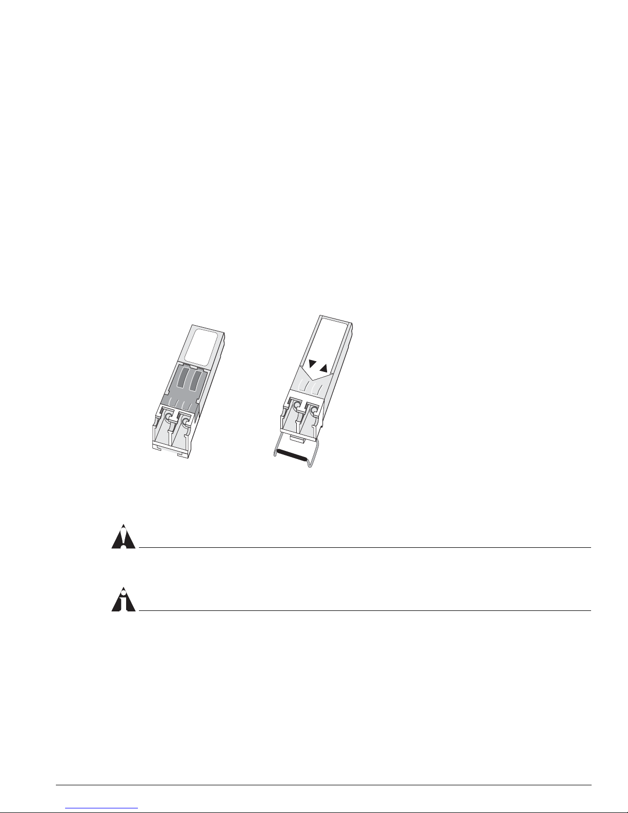
module, or Alpine GM-16X3 module without powering off the system. Figure 1 shows the two
types of mini-GBIC connectors.
Figure 1: Mini-GBIC modules
Mini-GBICs are a 3.3 V Class 1 laser devices. Use only Extreme-approved devices.
CAUTION
Mini-GBICs can emit invisible laser radiation. Avoid direct eye exposure to beam.
NOTE
Remove the LC fiber-optic connector from the mini-GBIC prior to removing the mini-GBIC from the
switch.
If you see an amber blinking mini-GBIC port status LED on your Summit48si switch, a BlackDiamond
G16X
3
module, or an Alpine GM-16X3 module, the mini-GBIC installed in your switch or module is not
approved, supported, or certified by Extreme Networks. To correct this problem, ensure that you install
an Extreme Networks-certified mini-GBIC.
XM_024
Module A Module B

22 Extreme Networks Consolidated "i" Series Hardware Installation Guide
Summary of Common Switch Features
To remove a mini-GBIC similar to the one labeled “Module A” in Figure 1, gently depress and hold the
black plastic tab at the bottom of the connector to release the mini-GBIC, and pull the mini-GBIC out of
the SFP receptacle.
To remove a mini-GBIC connector similar to the one labeled “Module B” in Figure 1, gently rotate the
front handle and pull the mini-GBIC out of the SFP receptacle.
To insert a mini-GBIC connector:
NOTE
Mini-GBICs can be installed in the SFP mini-GBIC receptacles only.
1 Holding the mini-GBIC by its sides, insert the mini-GBIC into the SFP receptacle on the switch or
module.
2 Slide the mini-GBIC into the SFP receptacle until you hear an audible click, indicating the mini-GBIC
is securely seated into the SFP receptacle. If the mini-GBIC has a handle, push up on the handle to
secure the mini-GBIC.
GBIC Type and Hardware/Software Support
Most Extreme Networks switches support two types of GBICs: the Parallel ID GBIC and the Serial ID
GBIC. The switch can identify the media type for the GBIC that is installed. Initial ExtremeWare
software versions do not support Serial ID GBICs. If Serial ID GBICs are installed in a switch with an
initial software release, the switch will not bring up the link on GBIC ports.
GBIC Media Types and Distances
Table 8 describes the media types and associated maximum distances for each GBIC type.
Table 8: GBIC types and maximum distances
Standard Media Type
Mhz•Km
Rating
Maximum
Distance (Meters)
SX
(850 nm optical window)
50/125 µm multimode fiber
50/125 µm multimode fiber
62.5/125 µm multimode fiber
62.5/125 µm multimode fiber
400
500
160
200
500
550
220
275
LX
(1310 nm optical window)
50/125 µm multimode fiber
50/125 µm multimode fiber
62.5/125 µm multimode fiber
10/125 µm single-mode fiber
10/125 µm single-mode fiber*
400
500
500
–
–
550
550
550
5,000
10,000
ZX
(1550 nm optical window)
10/125 µm single-mode fiber – 50,000
ZX Rev 03
(1550 nm optical window)
10/125 µm single-mode fiber 70,000

GBIC Type and Hardware/Software Support
Extreme Networks Consolidated "i" Series Hardware Installation Guide 23
*Extreme Networks proprietary. Connections between two Extreme Networks 1000BASE-LX interfaces can use a maximum distance of 10,000
meters.
GBIC Specifications
Table 9 through Table 15 describe the specifications for each GBIC type.
LX70
(1550 nm optical window)
10/125 µm single-mode fiber – 70,000
LX100
(1550 nm optical window)
10/125 µm single-mode fiber 100,000
UTP Category 5 UTP cable – 80
Table 9: 1000BASE-SX specifications
Parameter Minimum Typical Maximum
Transceiver
Optical output power -9.5 dBm -4 dBm
Center wavelength 830 nm 850 nm 860 nm
Receiver
Optical input power sensitivity -17 dBm
Optical input power maximum 0 dBm
Operating wavelength 830 nm 860 nm
Table 10: 100BASE-LX specifications
Parameter Minimum Typical Maximum
Transceiver
Optical output power -11 dBm -3 dBm
Center wavelength 1270 nm 1310 nm 1355 nm
Receiver
Optical input power sensitivity -19 dBm
Optical input power maximum -3 dBm
Operating wavelength 1270 nm 1355 nm
Table 11: ZX GBIC specifications
Parameter Minimum Typical Maximum
Transceiver
Optical output power -4 dBm -3 dBm -1 dBm
Table 8: GBIC types and maximum distances (continued)
Standard Media Type
Mhz•Km
Rating
Maximum
Distance (Meters)

24 Extreme Networks Consolidated "i" Series Hardware Installation Guide
Summary of Common Switch Features
Identifying ZX GBIC Rev 03 Modules
To identify the type of ZX GBIC module you have, look at the label on the top of the ZX GBIC module.
If you see one of the following on the label, you have a ZX GBIC Rev 03 module:
• DVA-1203 sticker near the top of the label that covers the Extreme Networks logo
• ZX GBIC (1203) text near the top of the label
• ZX GBIC Rev 03 text near the center of the label
Center wavelength 1540 nm 1550 nm 1570 nm
Receiver
Optical input power sensitivity -23.5 dBm
Optical input power maximum -1 dBm
Operating wavelength 1540 nm 1550 nm 1570 nm
Table 12: ZX GBIC Rev 03 specifications
Parameter Minimum Typical Maximum
Transceiver
Optical output power -2 dBm 0 dBm 2 dBm
Center wavelength 1540 nm 1550 nm 1570 nm
Receiver
Optical input power sensitivity -23 dBm
Optical input power maximum -1 dBm
Operating wavelength 1540 nm 1550 nm 1570 nm
Table 13: LX70 GBIC specifications
Parameter Minimum Typical Maximum
Transceiver
Optical output power 0 dBm 3 dBm 5.2 dBm
Center wavelength 1540 nm 1550 nm 1570 nm
Receiver
Optical input power sensitivity -22 dBm
Optical input power maximum -3 dBm
Operating wavelength 1270 nm 1570 nm
Table 11: ZX GBIC specifications (continued)
Parameter Minimum Typical Maximum

GBIC Type and Hardware/Software Support
Extreme Networks Consolidated "i" Series Hardware Installation Guide 25
Requirements for the LX100 GBIC
This section describes the requirements for the LX100 GBIC. Read the information in this section before
you install an LX100 GBIC.
If you have an Alpine 3800 series switch populated with a GM-4Xi module, do one of the following:
• Install a maximum of three LX100 GBICs per GM-4Xi module; the fourth GBIC slot must remain
empty
• Install two or less LX100 GBICs per GM-4Xi module and leave the remaining GBIC slots empty
• Install two or less LX100 GBICs per GM-4Xi module and install any combination of the following
GBICs into the empty slots:
— 1000BASE-SX
— 1000BASE-LX
— ZX GBIC
— ZX Rev 03
— LX70
— UTP GBIC
To ensure correct operation of the LX100 GBIC, make sure that you run ExtremeWare 6.1.9 or later on
your switch.
Requirements for the UTP GBIC
The UTP GBIC operates in full-duplex mode only. The UTP GBIC does not operate in 10/100 Mbps
mode, and it does not support autonegotiation of link speed.
You need to disable autonegotiation on the ports that use the UTP GBIC and manually configure the
port speed to 1000 Mbps.
Table 14: LX100 GBIC specifications
Parameter Minimum Typical Maximum
Transceiver
Optical output power 1 dBm 3 dBm 5 dBm
Center wavelength 1546 nm 1551 nm 1557 nm
Receiver
Optical input power sensitivity -29 dBm
Optical input power maximum -7 dBm
Operating wavelength 1546 nm 1551 nm 1557 nm
Table 15: UTP GBIC specifications
Media Type
Bit Error Rate
(Errors per Second)
Data
Rate
Min Distance
(Meters)
Max Distance
(Meters)
Category 5 UTP cable 10
-12
1 Gbps 2 80
26 Extreme Networks Consolidated "i" Series Hardware Installation Guide
Summary of Common Switch Features
The following example disables autonegotiation, configures a port speed of 1000 Mbps, and specifies
full-duplex mode for port 4 on a stand-alone switch:
config ports 4 auto off speed 1000 duplex full
The following example disables autonegotiation, configures a port speed of 1000 Mbps, and specifies
full-duplex mode for port 1 on a G8Xi module located in slot 1 of a modular switch:
config ports 1:1 auto off speed 1000 duplex full
The UTP GBIC is supported on “i” series products only.
Long Range GBIC System Budgets
Measure cable plant losses with a 1550 nm light source and verify this to be within budget. When
calculating the maximum distance attainable, using optical cable with a specified loss per kilometer (for
example, 0.25 db/km), Extreme Networks recommends that 3 dB of the total budget be reserved for
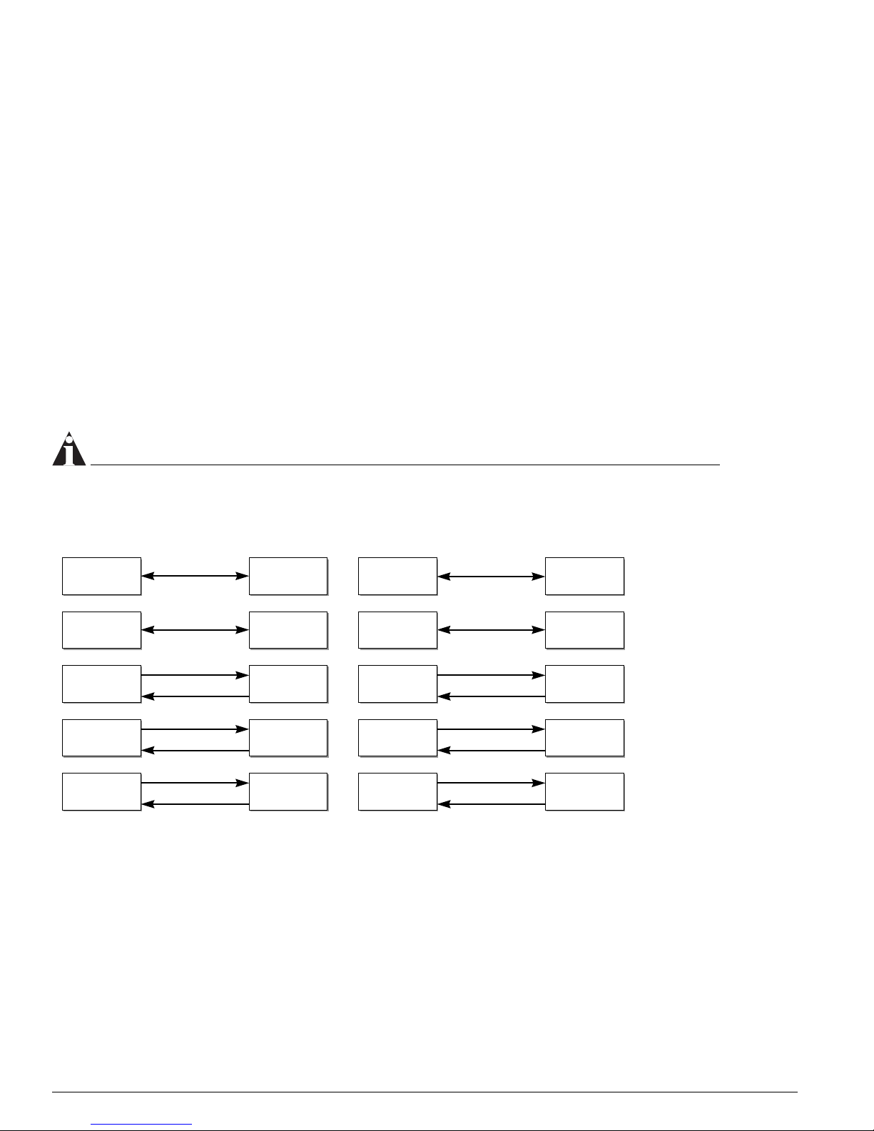
losses induced by cable splices, connectors, and operating margin. Figure 2 shows the total optical
system budget between long range GBICs.
NOTE
The fiber loss budget plus all other penalties must not exceed the total optical system budget.
Figure 2: Total optical system budgets for long range GBICs
The ZX mini-GBIC is equivalent to the ZX Rev 03 GBIC.
XM_041
ZX GBIC
ZX GBIC
Rev. 03
ZX GBIC
Rev. 03
ZX GBIC
Rev. 03
21.0 dB
19.5 dB
ZX GBIC ZX GBIC
LX70 LX70
18.0 dB
23.5 dB
ZX GBIC LX70
29.0 dB
23.0 dB
19.0 dB
21.5 dB
23.0 dB
20.0 dB
LX70 LX100
LX100
LX100
30.0 dB
ZX GBIC
ZX GBIC
Rev. 03
LX100 LX100
25.0 dB
24.5 dB
27.0 dB
24.0 dB
LX70
ZX GBIC
Rev. 03
22.0 dB

GBIC Type and Hardware/Software Support
Extreme Networks Consolidated "i" Series Hardware Installation Guide 27
Table 16 lists the minimum attenuations that are required by each long range GBIC to prevent saturation
of the receiver.
The ZX mini-GBIC is equivalent to the ZX Rev 03 GBIC.
Safety Information
Before you install or replace a GBIC, read the safety information in this section.
CAUTION
GBICs can emit invisible laser radiation. Avoid direct eye exposure to beam.
GBICs are class 1 laser devices, and they operate at 5 V. Use only Extreme-approved devices.
Remove the SC fiber-optic or the RJ-45 connector from the GBIC prior to removing the GBIC from the
I/O module or the switch.
Preparing to Install or Replace a GBIC
This section describes the preparation steps that you must perform before inserting and securing a
GBIC.
CAUTION
GBICs can emit invisible laser radiation. Avoid direct eye exposure to beam.
To ensure proper installation, complete the following five tasks before inserting the GBIC:
1 Inspect and clean the fiber tips, coupler, and connectors.
2 Prepare and clean an external attenuator, if needed.
3 Calculate the link budget.
4 Do not stretch the fiber.
5 Make sure the bend radius of the fiber is not less than 2 inches.
Table 16: Minimum attenuation requirements
Receivers
GBIC Type LX70
ZX (prior to
Rev 03)
ZX Rev 03 LX100
LX70 10 dB 10 dB 10 dB 11 dB
Transceivers ZX (prior to
Rev 03)
0 dB 0 dB 0 dB 8 dB
ZX Rev 03 8 dB 8 dB 8 dB 9 dB
LX100 11 dB 11 dB 11 dB 12 dB
28 Extreme Networks Consolidated "i" Series Hardware Installation Guide
Summary of Common Switch Features
In addition to the previously described tasks, Extreme Networks recommends the following when
installing or replacing GBICs on an active network:
• Use the same type of GBIC at each end of the link.
• Connect one end of the link to the Tx port. Without an attenuator, measure the total loss from the Tx
port to the other site of the link. The total loss must not exceed the total optical system budget listed
in Figure 2.
• Use dispersion shifted fiber whenever possible. This provides superior performance in the 1550 nm
range.
After you complete all of these described tasks, you are ready to install or replace a GBIC.
Installing or Replacing a GBIC
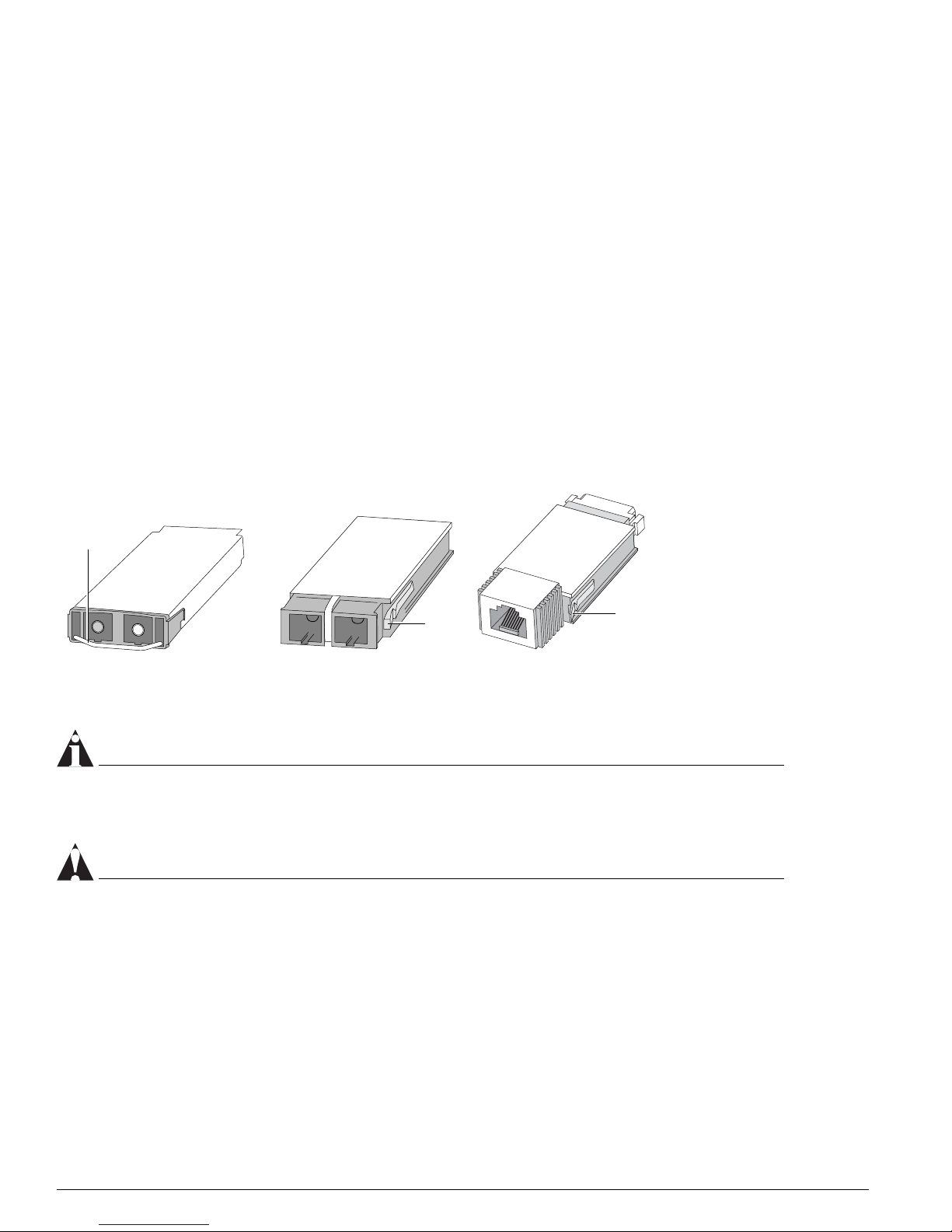
You can add and remove GBICs from your Extreme Networks switch without powering off the system.
Figure 3 shows the three types of GBIC connectors.
Figure 3: GBIC modules
GBICs are a Class 1 laser device. Use only Extreme-approved devices.
NOTE
Remove the SC fiber-optic or the RJ-45 connector from the GBIC prior to removing the GBIC from the
I/O module or the switch.
CAUTION
GBICs can emit invisible laser radiation. Avoid direct eye exposure to beam.
To remove a GBIC connector similar to the one labeled “Module A” in Figure 3, gently rotate the front
handle up and pull the GBIC out of the slot.
To remove a GBIC connector similar to one labeled “Module B” or “Module C” in Figure 3, gently
squeeze the sides to release the GBIC, and pull the GBIC out of the slot.
EW_GBIC
Module A Module B Module C
Handle
Ta b
Ta b

GBIC Type and Hardware/Software Support
Extreme Networks Consolidated "i" Series Hardware Installation Guide 29
To insert a GBIC connector:
1 Holding the GBIC by its sides, insert the GBIC into the slot on the I/O module or the switch.
2 Slide the GBIC into the slot until you hear an audible click, indicating the GBIC is securely seated. If
the GBIC has a handle, push down on the handle to secure the GBIC.

30 Extreme Networks Consolidated "i" Series Hardware Installation Guide
Summary of Common Switch Features
 Loading...