

Extreme Networks SSA-G8018-0652, SSA-T8028-0652, SSA S180 Class Hardware Installation Manual

S-Series Stand Alone (SSA)
Switch Hardware Installation
Guide
SSA S180 Class
SSA-T8028-0652
SSA-G8018-0652
9035039
Published December 2016

Copyright © 2017 Extreme Networks, Inc. All rights reserved.
Legal Notice
Extreme Networks, Inc. reserves the right to make changes in specifications and other information
contained in this document and its website without prior notice. The reader should in all cases
consult representatives of Extreme Networks to determine whether any such changes have been
made.
The hardware, firmware, software or any specifications described or referred to in this document
are subject to change without notice.
Trademarks
Extreme Networks and the Extreme Networks logo are trademarks or registered trademarks of
Extreme Networks, Inc. in the United States and/or other countries.
All other names (including any product names) mentioned in this document are the property of
their respective owners and may be trademarks or registered trademarks of their respective
companies/owners.
For additional information on Extreme Networks trademarks, please see:
www.extremenetworks.com/company/legal/trademarks
Support
For product support, phone the Global Technical Assistance Center (GTAC) at 1-800-998-2408
(toll-free in U.S. and Canada) or +1-408-579-2826. For the support phone number in other
countries, visit: http://www.extremenetworks.com/support/contact/
For product documentation online, visit: https://www.extremenetworks.com/documentation/
For information, contact:
Extreme Networks, Inc.
6480 Via Del Oro
San Jose, California 95119
USA

Table of Contents
About this Guide........................................................................................................................ 5
Who Should Use this Guide............................................................................................................................................. 5
How to Use This Guide.......................................................................................................................................................5
Text Conventions...................................................................................................................................................................6
Providing Feedback to Us................................................................................................................................................ 6
Getting Help.............................................................................................................................................................................7
Related Publications............................................................................................................................................................ 7
Chapter 1: Introduction..............................................................................................................8
SSA-T8028-0652.................................................................................................................................................................. 8
SSA-G8018-0652...................................................................................................................................................................9
AC Power Supplies............................................................................................................................................................... 9
Fans............................................................................................................................................................................................10
Micro-USB Port.....................................................................................................................................................................10
Management..........................................................................................................................................................................10
Virtual Switch Bonding.....................................................................................................................................................10
Chapter 2: Installation.............................................................................................................. 11
Required Tools........................................................................................................................................................................11
Installation Site Requirements.......................................................................................................................................12
Unpacking the SSA Switch............................................................................................................................................. 12
Mounting the SSA Switch................................................................................................................................................13
Unpacking the Power Supplies....................................................................................................................................22
Installing the Power Supplies........................................................................................................................................23
Powering Up the SSA Switch........................................................................................................................................25
Installing the Power Cord Retention Clip Assembly......................................................................................... 26
Connecting Your SSA Switch to the Network......................................................................................................27
Connecting Two SSA Chassis for Virtual Switch Bonding.............................................................................30
Connecting to a Local Management Console......................................................................................................30
Completing the Installation............................................................................................................................................32
Chapter 3: Troubleshooting................................................................................................... 34
LEDs..........................................................................................................................................................................................34
Troubleshooting Checklist..............................................................................................................................................38
Replacing the SSA Fan Module...................................................................................................................................39
Removing a Power Supply............................................................................................................................................ 40
Shutting Down the SSA Switch Using the OFFLINE/RESET Button........................................................42
Appendix A: Specifications....................................................................................................44
SSA Switch Specifications.............................................................................................................................................44
Pluggable Transceiver Specifications.......................................................................................................................45
COM Port Pinout Assignments....................................................................................................................................45
Compliance............................................................................................................................................................................45
Appendix B: Clearing Persistent Storage or Resetting the System Password............... 47
Clearing the Persistent Storage or Resetting the Password Using the Boot Loader.......................47
Clearing the System Storage or Resetting the Password Using the Mode Switches.......................48
Appendix C: Optional Rack Mount Rail Kit Installation..................................................... 52
Required Tools......................................................................................................................................................................52
S-Series Stand Alone (SSA) Switch Hardware Installation Guide 3

Table of Contents
Installation Site Requirements......................................................................................................................................53
Contents of the Mounting Kit.......................................................................................................................................53
Removing the Rack Mount Ears from the SSA Switch.................................................................................... 54
Installing the Adapter Plates.........................................................................................................................................54
Four-Post Rack Mount Installation............................................................................................................................ 56
Two-Post Rack Mount Installation..............................................................................................................................59
Appendix D: Installing the SSA-WALL-MOUNT Kit.............................................................67
Required Tools..................................................................................................................................................................... 67
Installation Site Requirements......................................................................................................................................67
Contents of the SSA-WALL-MOUNT Kit.................................................................................................................67
Preparing the Installation Site......................................................................................................................................68
Mounting the SSA Chassis on a Wall........................................................................................................................70
Appendix E: Regulatory Compliance....................................................................................76
Safety Information............................................................................................................................................................. 79
Declaration of Conformity...............................................................................................................................................81
Index.......................................................................................................................................... 83
S-Series Stand Alone (SSA) Switch Hardware Installation Guide 4
About this Guide
This guide provides an overview, installation, troubleshooting, and optional rack mount rail kit
installation instructions, and specifications for the Extreme Networks S-Series® Stand Alone (SSA)
switch models:
SSA-T8028-0652
•
SSA-G8018-0652
•
Who Should Use this Guide
Warning
Electrical hazard: Only qualified personnel should perform installation procedures.
Riesgo Electrico: Solamente personal calificado debe realizar procedimientos de instalacion.
Elektrischer Gefahrenhinweis: Installationen sollten nur durch ausgebildetes und qualifiziertes
Personal vorgenommen werden.
Risques d'électrocution: Seul un personnel qualifié doit eectuer les procédures d'installation.
This guide is intended for a network administrator who is responsible for installing and setting up the
SSA switch.
How to Use This Guide
Read through this guide completely to familiarize yourself with its contents and to gain an
understanding of the features and capabilities of the SSA switch. A general working knowledge of data
communications networks is helpful when setting up the SSA switch.
For...
An overview of the SSA switch and its features Introduction on page 8
Instructions for installing the SSA switch hardware and
connecting the SSA switch to the network
Information on port, system, and power supply LEDs; how to
replace fan modules and power supplies; and how to restart or
shut down the SSA switch using the OFFLINE/RESET button
Specifications, environmental requirements, and physical
properties of the SSA switch
Details on how to clear either the persistent storage or the system
password as troubleshooting tools
Details on how to install the optional rack mount kit Optional Rack Mount Rail Kit Installation on
Details on how to install the optional wall mounting bracket Installing the SSA-WALL-MOUNT Kit on page
Detailed compliance information for the SSA switch Regulatory Compliance on page 76
Refer to...
Installation on page 11
Troubleshooting on page 34
Specifications on page 44
Clearing Persistent Storage or Resetting the
System Password on page 47
page 52
67
Environmental guidelines such as operating temperature, airflow,
inlet temperature, and dust mitigation and prevention
S-Series Stand Alone (SSA) Switch Hardware Installation Guide 5
Environmental Guidelines for
ExtremeSwitching Products
Text Conventions
The following tables list text conventions that are used throughout this guide.
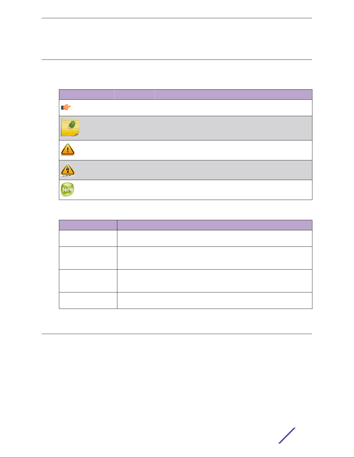
Table 1: Notice Icons
Icon Notice Type Alerts you to...
General Notice Helpful tips and notices for using the product.
Note Important features or instructions.
Caution Risk of personal injury, system damage, or loss of data.
Warning Risk of severe personal injury.
About this Guide
New This command or section is new for this release.
Table 2: Text Conventions
Convention Description
Screen displays
The words enter and
type
[Key] names Key names are written with brackets, such as [Return] or [Esc]. If you must press two
Words in italicized type Italics emphasize a point or denote new terms at the place where they are defined in
This typeface indicates command syntax, or represents information as it appears on the
screen.
When you see the word “enter” in this guide, you must type something, and then press
the Return or Enter key. Do not press the Return or Enter key when an instruction
simply says “type.”
or more keys simultaneously, the key names are linked with a plus sign (+). Example:
Press [Ctrl]+[Alt]+[Del]
the text. Italics are also used when referring to publication titles.
Providing Feedback to Us
We are always striving to improve our documentation and help you work better, so we want to hear
from you! We welcome all feedback but especially want to know about:
Content errors or confusing or conflicting information.
•
Ideas for improvements to our documentation so you can find the information you need faster.
•
Broken links or usability issues.
•
If you would like to provide feedback to the Extreme Networks Information Development team about
this document, please contact us using our short online feedback form. You can also email us directly at
internalinfodev@extremenetworks.com.
S-Series Stand Alone (SSA) Switch Hardware Installation Guide 6

Getting Help
If you require assistance, contact Extreme Networks using one of the following methods:
GTAC (Global Technical Assistance Center) for Immediate Support
•
Phone: 1-800-998-2408 (toll-free in U.S. and Canada) or +1 408-579-2826. For the support
•
phone number in your country, visit: www.extremenetworks.com/support/contact
Email: support@extremenetworks.com. To expedite your message, enter the product name or
•
model number in the subject line.
GTAC Knowledge — Get on-demand and tested resolutions from the GTAC Knowledgebase, or
•
create a help case if you need more guidance.
The Hub — A forum for Extreme customers to connect with one another, get questions answered,
•
share ideas and feedback, and get problems solved. This community is monitored by Extreme
Networks employees, but is not intended to replace specific guidance from GTAC.
Support Portal — Manage cases, downloads, service contracts, product licensing, and training and
•
certifications.
Before contacting Extreme Networks for technical support, have the following information ready:
Your Extreme Networks service contract number and/or serial numbers for all involved Extreme
•
Networks products
A description of the failure
•
A description of any action(s) already taken to resolve the problem
•
A description of your network environment (such as layout, cable type, other relevant environmental
•
information)
Network load at the time of trouble (if known)
•
The device history (for example, if you have returned the device before, or if this is a recurring
•
problem)
Any related RMA (Return Material Authorization) numbers
•
About this Guide
Related Publications
S-, K-, and 7100-Series Documentation
S-, K-, and 7100 Series CLI Reference Guide
•
S-, K-, and 7100 Series Configuration Guide
•
Environmental Guidelines for ExtremeSwitching Products
•
Other S-, K-, and 7100-Series documentation is available at: https://extranet.extremenetworks.com/.
You must have a valid customer account to access this site.
S-Series Stand Alone (SSA) Switch Hardware Installation Guide 7
1 Introduction
SSA-T8028-0652
SSA-G8018-0652
AC Power Supplies
Fans
Micro-USB Port
Management
Virtual Switch Bonding
This chapter provides an overview of the capabilities of the following Extreme Networks S-Series SSA
models:
SSA-T8028-0652
•
SSA-G8018-0652
•
For information about firmware features of the SSA switch and how to configure them, refer to the S-,
K-, and 7100 Series Configuration Guide.
SSA-T8028-0652
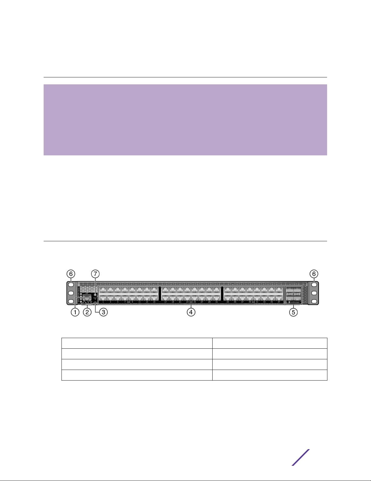
The SSA-T8028-0652 has forty-eight 10/100/1000BASE-T RJ45 ports and four 10GBASE-X SFP+ ports,
as shown in Figure 1.
Figure 1: SSA-T8028-0652 I/O Port Panel
1 = COM port
2 = System LEDs 6 = Mounting ears
3 = Micro-USB port 7 = Ground receptacle
4 = 10/100/1000BASE-T RJ45 ports
Each of the 10/100/1000BASE-T RJ45 ports operates in full-duplex mode.
The SFP+ ports support a number of pluggable transceivers. For more information about the
transceivers, see http://www.extremenetworks.com/product/transceivers/.
5 = 10GBASE-X SFP+ ports
S-Series Stand Alone (SSA) Switch Hardware Installation Guide 8
SSA-G8018-0652
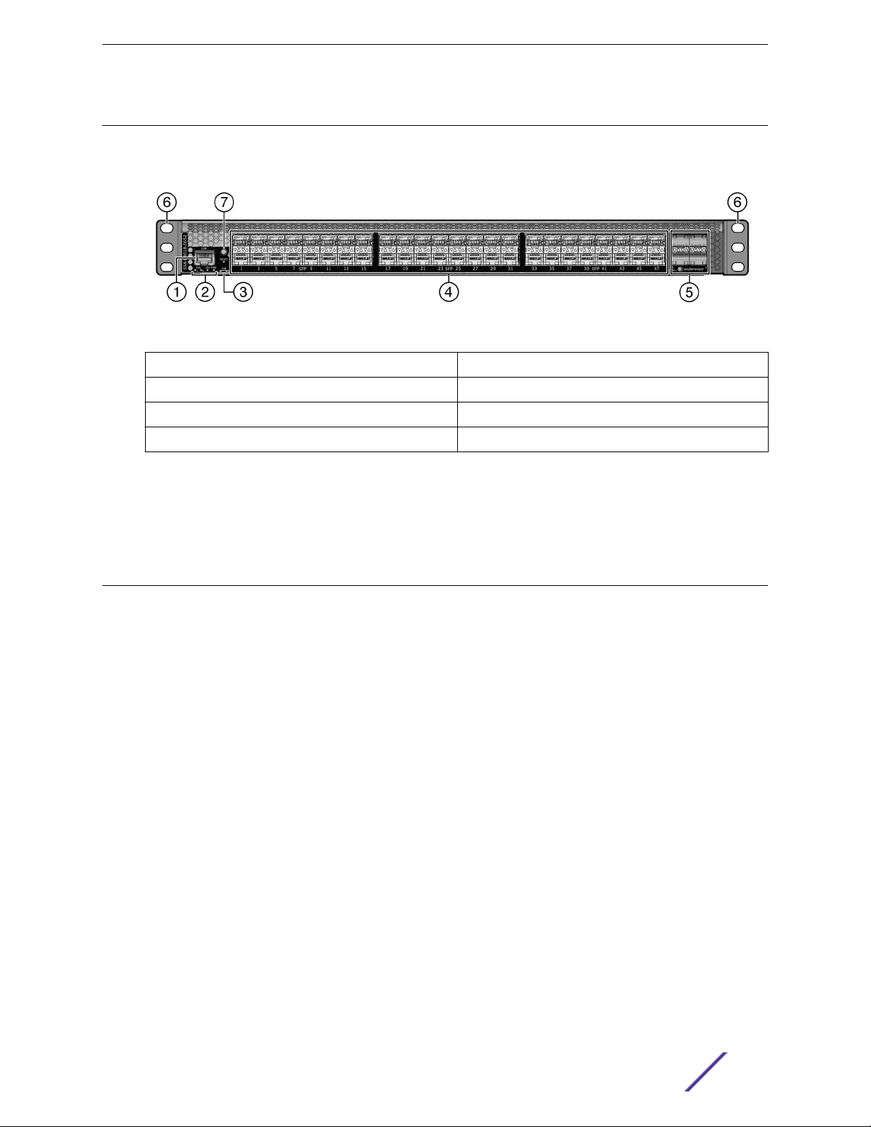
The SSA-G8018-0652 has forty-eight 1000BASE-X SFP ports and four 10GBASE-X SFP+ ports, as
shown in Figure 2.
Figure 2: SSA-G8018-0652 I/O Port Panel
1 = COM port 5 = 10GBASE-X SFP+ ports
2 = System LEDs 6 = Mounting ears
3 = Micro-USB port 7 = Ground receptacle
4 = 1000BASE-X SFP ports
Introduction
Each of the 1000BASE-X SFP ports operates in full-duplex mode.
The SFP and SFP+ ports support a number of pluggable transceivers. For more information about the
transceivers, see http://www.extremenetworks.com/product/transceivers/.
AC Power Supplies
Two 460 watt AC power supply models, ordered separately, are available for the SSA switch:
SSA-FB-AC-PS-A—I/O port side air exhaust
•
SSA-FB-AC-PS-B—I/O port side air intake
•
Each power supply option contains a single non-reversible fan. The two power supply options are
dierentiated by the direction of the power supply fan airflow. Power supply airflow must agree with
the airflow direction of the installed fan modules.
The SSA AC power supplies automatically adjust to the input voltage and frequency, which allows for an
input voltage of 100 to 240 VAC, and a frequency between 50 and 60 Hz. See the operating
specifications in SSA Switch Specifications on page 44. No additional adjustments are necessary. For
installations in North America, a 15 Amp power cord is required. See Powering Up the SSA Switch on
page 25 for more details.
You can install up to two power supplies in the rear of the SSA chassis. All the power supply needs of
the SSA switch can be met by installing a single power supply. If you choose to use two power supplies,
system power redundancy is guaranteed if one supply is lost. Power supplies are hot swappable in
redundant power supply mode.
For more information, see Installing the Power Supplies on page 23.
For information about the power supply LED, see Table 14 on page 38.
S-Series Stand Alone (SSA) Switch Hardware Installation Guide 9

Fans
The SSA switch comes with two installed fan modules to cool the system. The direction of the fan
module airflow is reversible. By default airflows from the I/O port side to the power supply side of the
unit. If your SSA switch configuration requires power supply side to I/O port side airflow, see Reversing
the Fan Module Airflow on page 15 for details about how to reverse the fan module airflow.
The SSA fan modules are both field replaceable and hot swappable. For information on how to replace
SSA fan modules, see Replacing the SSA Fan Module on page 39.
Micro-USB Port
The micro-USB port is provided for local file transfer.
Management
You can manage the SSA switch either in-band or out-of-band.
In-band remote management is possible using the Extreme Networks’ Extreme Management Center
application or the command line interface (CLI) via Telnet.
Introduction
Out-of-band management is provided through the RJ45 COM (Communication) port on the front panel
using a PC, a VT terminal, or a VT terminal emulator. For more information, see Connecting Your SSA
Switch to the Network on page 27.
Virtual Switch Bonding
For data center redundancy, you can configure two co-located SSA chassis to operate as a single logical
chassis managed by one IP address. This is known as a virtual switch bonded chassis. We recommend
connecting the chassis to each other by using at least two 10G ports on each SSA chassis.
For details on how to configure virtual switch bonding, see the S-, K-, and 7100 Series Configuration
Guide.
S-Series Stand Alone (SSA) Switch Hardware Installation Guide 10
2 Installation
Required Tools
Installation Site Requirements
Unpacking the SSA Switch
Mounting the SSA Switch
Unpacking the Power Supplies
Installing the Power Supplies
Powering Up the SSA Switch
Installing the Power Cord Retention Clip Assembly
Connecting Your SSA Switch to the Network
Connecting Two SSA Chassis for Virtual Switch Bonding
Connecting to a Local Management Console
Completing the Installation
Warning
Electrical hazard: Only qualified personnel should perform installation procedures.
Riesgo Electrico: Solamente personal calificado debe realizar procedimientos de instalacion.
Elektrischer Gefahrenhinweis: Installationen sollten nur durch ausgebildetes und qualifiziertes
Personal vorgenommen werden.
Risques d'électrocution: Seul un personnel qualifié doit eectuer les procédures d'installation.
Warning
To prevent possible injury when installing your Extreme Networks switch product, avoid
contacting the edges of I/O ports with your fingers.
Advertencia: Para evitar posibles lesiones durante la instalación de su producto interruptor
Extreme Networks, evite tocar con los dedos los bordes de los puertos de entrada/salida.
Warnhinweis: Verletzungsgefahr beim Installieren des Extreme Networks Switch – berühren
Sie die Ränder der E/A-Anschlüsse nicht mit den Fingern.
Avertissements: Afin d'éviter toute blessure possible lors de l'installation de votre
commutateur Extreme Networks, évitez que vos doigts touchent les rebords des ports
d'entrée et de sortie.
Use the following topics, in order, to install your product.
Required Tools
To install your equipment, you will need the following tools:
ESD wrist strap (included with the SSA switch)
•
Phillips screwdriver
•
S-Series Stand Alone (SSA) Switch Hardware Installation Guide 11
Installation Site Requirements
Depending upon the cabling used, you need to provide 7.5 to 10 cm (3 to 4 in.) of clearance on the
switch I/O port side of the SSA switch.
See Environmental Guidelines for ExtremeSwitching Products for environmental guidelines relating to
the SSA switch installation.
The installation site must be within reach of the network cabling and must meet the requirements listed
below:
Appropriate grounded power receptacles must be located within 2 meters (7 feet) of the site.
•
A temperature of between 5°C (41°F) and 40°C (104°F) must be maintained at the installation site
•
with fluctuations of less than 10°C (18°F) per hour.
Caution
To ensure proper ventilation and prevent overheating, leave a minimum clearance space of 5.1
cm (2.0 in.) at the front and rear of the device.
Precaución: Para asegurar una buena ventilación y evitar que el sistema se sobrecaliente, deje
un espacio mìnimo de 5.1 cm (2 pulgadas) con respecto el anverso y reverso del aparato.
Installation
Unpacking the SSA Switch
Unpack the SSA switch as follows:
1 Open the box and remove the packing material protecting the SSA switch.
Save the shipping box and materials in case the unit must be reshipped.
2 Remove and set aside the RJ45-to-DB9 converter, anti-static wrist strap, adhesive feet (for flat
surface placement), and power cord retention clips.
The SSA switch does not include screws for attaching the SSA switch to rack posts.
3 Verify the contents of the carton as listed in Table 3.
Table 3: Contents of the SSA Switch Carton
Quantity Item
1 SSA chassis
1 RJ45 management cable
1 RJ45-to-DB9 converter
1 Anti-static wrist strap
4 Adhesive rubber feet
2 Power cord retention clips
1 SSA Quick Reference
4 Inspect the SSA switch for any signs of physical damage.
If there are any signs of damage, do not install the SSA switch; instead, contact us.
S-Series Stand Alone (SSA) Switch Hardware Installation Guide 12
Mounting the SSA Switch
Note
The SSA switch comes with integrated mounting ears that are adequate for most installations.
For slide-in mounting, high vibration, or high shock installations, an optional rack mount kit
(SSA-FB-MOUNTKIT) is available.
To install the SSA switch in a rack using the optional rack mount kit, follow the pre-installation
discussion here – including: Power Supply Airflow and Switch Fan Module Airflow on page 14
and Reversing the Fan Module Airflow on page 15 – before proceeding to Optional Rack
Mount Rail Kit Installation on page 52.
You can install a SSA switch on a flat surface or in a rack. For more information about flat surface
installation, see Installing the SSA Switch on a Flat Surface on page 22.
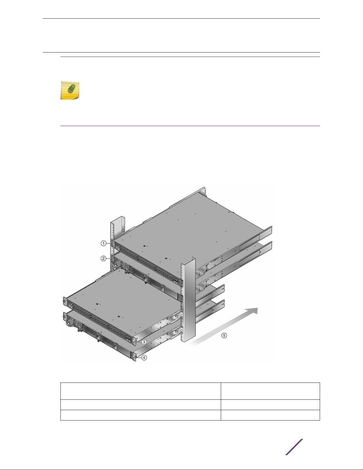
There are four possible rack mounting configurations as shown in Figure 3, based upon whether:
The switch I/O ports side or the power supply side of the device face front.
•
The device is mounted flush with the rack posts or mid-mounted.
•
Installation
Figure 3: SSA Switch Rack Configurations
1 = Flush mounted with the switch I/O ports facing front (cool air side)
2 = Flush mounted with the power supply facing front (cool air side) 5 = Airflow direction
3 = Mid-mounted with the switch I/O ports facing front
S-Series Stand Alone (SSA) Switch Hardware Installation Guide 13
4 = Mid-mounting with the power supply
facing front
Power Supply Airflow and Switch Fan Module Airflow
The power supply module has its own fan for cooling the power supply, and each of the two switch fan
modules has two fans for cooling the switch circuitry. The airflow direction of all three modules must
agree in order to properly cool the installed SSA system. In rack mount configurations the best practice
is to mount all devices with a common cool air side and a common exhaust (hot air) side.
On the SSA switch, two airflow directions are supported:
The I/O port side to the power supply side
•
The power supply side to the I/O port side
•
Note
The power supplies are ordered separately from the switch unit, and you must specify the
airflow direction when you order them. Power supply airflow direction is fixed and cannot be
changed manually. If the ordered power supply has an airflow direction that does not work for
your rack configuration, you must order another power supply that has the correct airflow
direction (see Table 5 on page 14).
The SSA switch, as shipped from the factory, is set up for airflow direction from the I/O port side to the
power supply side. If your installation requires that airflow direction be from the power supply side to
the I/O port side, you must reverse the airflow of the switch fan module fans (see Reversing the Fan
Module Airflow on page 15). Also, you must reverse the rack mount flanges (ears) (see Rack Mount Ear
Positioning on page 17).
Installation
You can determine airflow direction of the switch fan modules by visually inspecting them for whether a
white label or a fan blade is visible through the fan screen.
Before securing the SSA switch to the rack or installing the power supply into the SSA switch, unpack
the power supply module (see Unpacking the Power Supplies on page 22) and visually verify that its
airflow direction and that of the switch fan modules agree with the intended configuration as defined in
Table 4 and Table 5 on page 14.
Table 4: Switch Fan Module Airflow Direction
Airflow Direction Visual Indication
From I/O port side to power supply side White label is visible on fan unit
From power supply side to I/O port side Fan blade is visible on fan unit
The power supply airflow direction can also be verified using the power supply manufacturer’s part
number located on the power supply bottom label.
Table 5: Power Supply Airflow Based on Model Number
Model Number Mfg. Part Number Airflow Direction
SSA-FB-AC-PS-A DS460S-3-003 From power supply side to I/O port side
SSA-FB-AC-PS-B DS460S-3-002 From I/O port side to power supply side
S-Series Stand Alone (SSA) Switch Hardware Installation Guide 14
Reversing the Fan Module Airflow
If the SSA switch rack configuration requires the airflow to be from the power supply side to the I/O
port side, you must reverse the airflow in the switch fan modules for both switch fan module 1 and
switch fan module 2.
To reverse the airflow in the fan modules, perform the steps in the following topics:
Removing the Fan Module on page 15
•
Reversing the Fan Unit on page 15
•
Reinstalling the Fan Module on page 16
•
Removing the Fan Module
To remove the switch fan module, follow these steps:
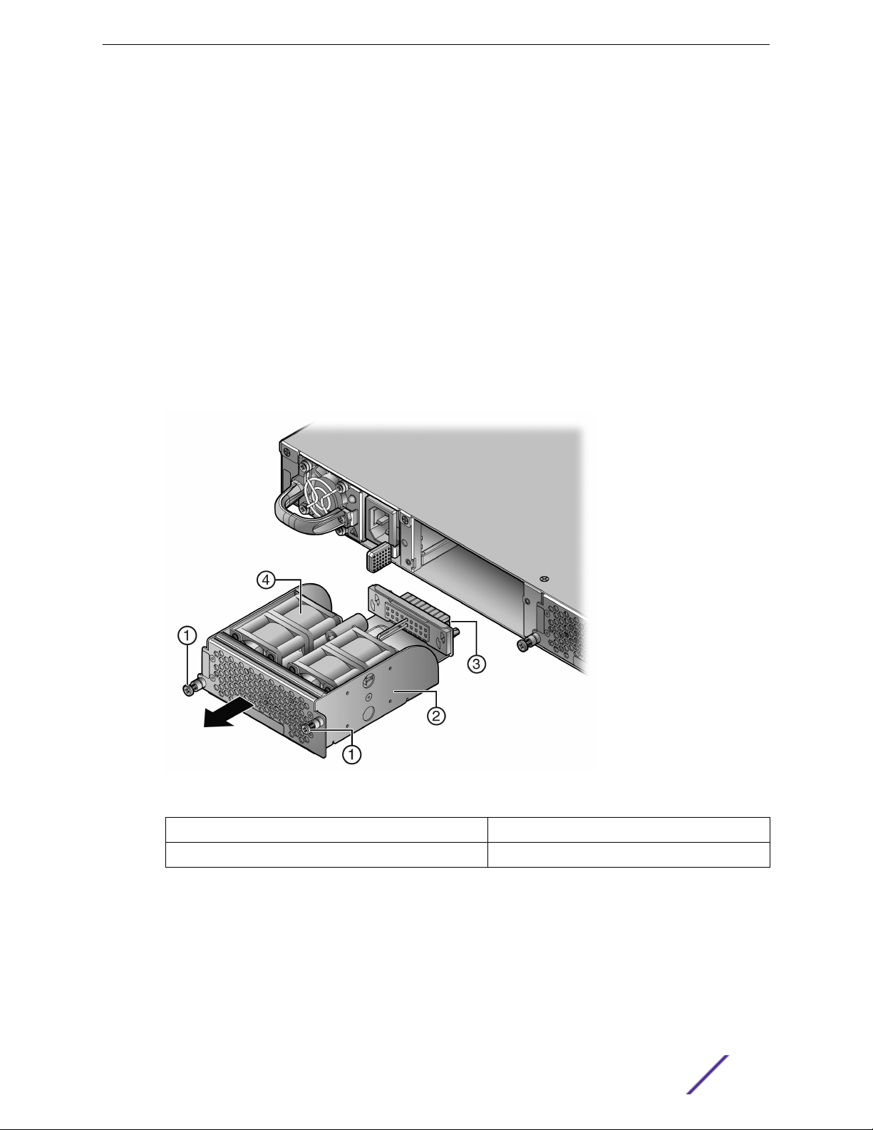
1 Unscrew the two fan module captive screws as shown in Figure 4.
2 Slide the fan module forward until it is unplugged from the device.
Installation
Figure 4: Removing the Switch Fan Module
1 = Fan module captive screws
2 = Switch Fan module 4 = Fan units
Reversing the Fan Unit
The switch fan module has a single reversible dual fan unit. When the fan unit is properly seated, the
airflow indicator arrow is completely visible as shown in callout 1, Figure 5 on page 16. The airflow
indicator arrow points in the direction the fan unit flows air through the fan module.
In the I/O port to power supply module (default) airflow configuration, the fan unit is visible (as shown
in Figure 4 on page 15, callout 4).
S-Series Stand Alone (SSA) Switch Hardware Installation Guide 15
3 = Fan module connector
Installation
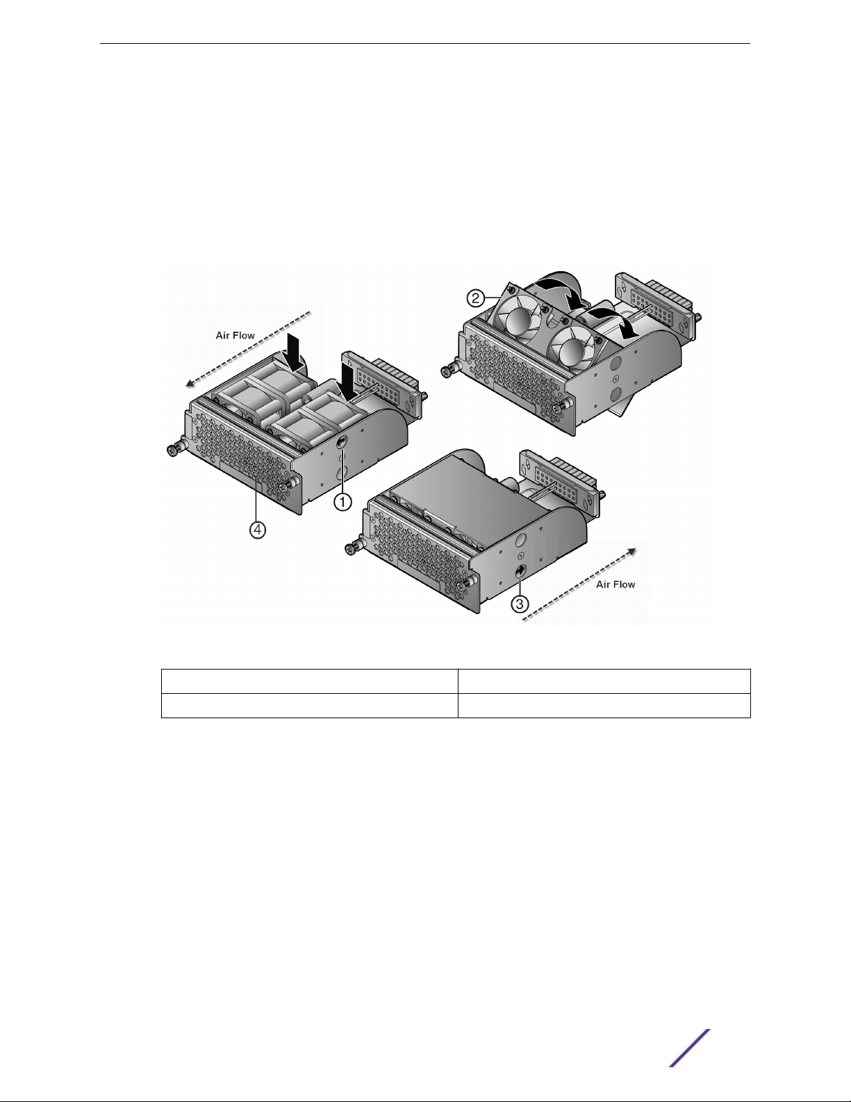
When the fan unit is reversed, a metal plate covers the fan unit (as shown in Figure 5 on page 16).
To reverse the fan module airflow, follow these steps:
1 Hold the module in your hand.
2 Apply pressure to the edges of the fan units closer to the fan module connector to rotate the fan
unit (thick black arrows in Figure 5).
3 Flip the fan unit 180 degrees until the airflow indicator is again completely visible and pointing away
the fan module screen, as shown in callout 4, Figure 5.
Figure 5: Reversing the Fan Module Airflow
Airflow indicator arrow 3 = Airflow indicator arrow
1 =
2 = Fan unit in mid-reversal 4 = Fan screen
Callout 1 shows airflow from the I/O port side to the power supply side of the module.
Callout 3 shows airflow from the power supply side to the I/O port side of the module.
Reinstalling the Fan Module
To reinstall the fan module, follow these steps:
1 Align the fan module with the fan module opening.
2 Insert the module into the fan module opening, applying enough pressure that the fan module is
flush with the device.
3 Secure the two fan module captive screws.
S-Series Stand Alone (SSA) Switch Hardware Installation Guide 16

Rack Mount Ear Positioning
If you are installing the SSA switch using the SSA-FB-MOUNTKIT optional rack mount kit, proceed to
Optional Rack Mount Rail Kit Installation on page 52.
When shipped from the factory, the SSA switch has rack mount ears attached to the edge of the side of
the switch containing the I/O ports in a flush mount configuration, as shown in callout 1, Figure 3 on
page 13. If you are mounting the switch using the factory positioning of the rack mount ears, go to
Securing the SSA Switch to the Rack on page 20.
The rack mount ears can be repositioned providing three alternative mounting options, which are
described in the following topics:
Flush-Mount Configuration with Power Supply Facing Front on page 17
•
Mid-Mount Configuration with I/O Ports Facing Front on page 18
•
Mid-Mount Configuration with Power Supply Facing Front on page 19
•
Flush-Mount Configuration with Power Supply Facing Front
The flush-mount, power supply facing front, configuration is depicted in callout 2, Figure 3 on page 13.
This SSA switch rack mount configuration requires the repositioning of the rack mount ears on both
sides of the device.
Installation
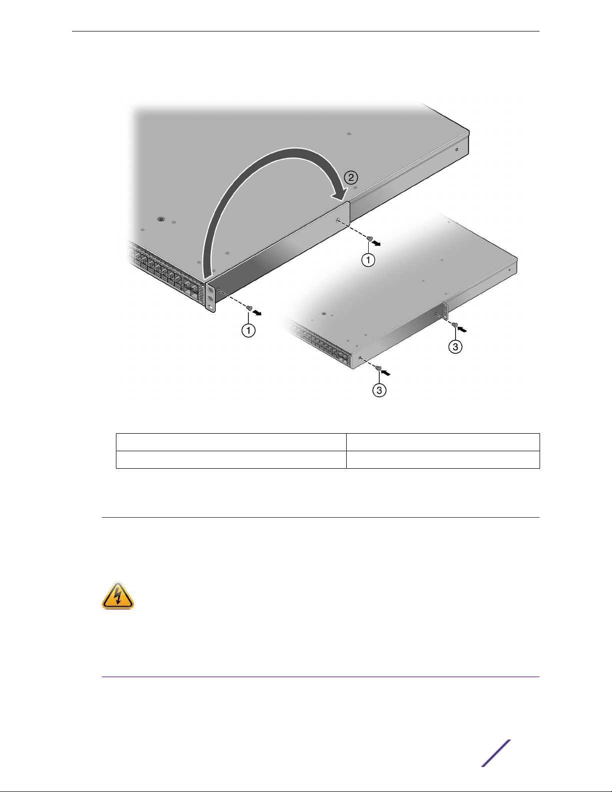
To reposition the rack mount ears for this configuration, follow these steps:
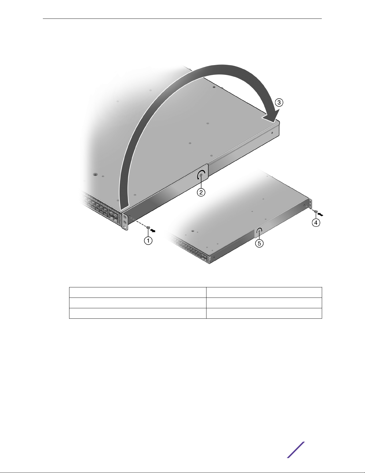
1 Remove the screw by the three holed ear, as shown in Figure 6 on page 18 callout 1, and loosen the
opposite screw, shown by callout 2.
2 Pivot the rack mount ear at the loosened screw, shown by callout 3, repositioning the rack mount ear
so that the three-holed ear is flush with the switch I/O port side of the device.
3 Reinsert the front screw, shown by callout 4, and retighten the middle screw, shown by callout 5.
S-Series Stand Alone (SSA) Switch Hardware Installation Guide 17
4 Repeat step 1 through step 3 on the other side of the chassis.
Installation
Figure 6: Flush Mount Power Supply Front Configuration
1 = Ear mount screw removal
2 = Rack mount ear pivot screw 5 = Pivot screw retightened
3 = Repositioning of rack mount ear
4 = Ear mount screw insertion
Mid-Mount Configuration with I/O Ports Facing Front
The mid-mount, I/O ports facing front configuration is depicted in callout 3, Figure 3 on page 13. This
rack mount configuration requires repositioning the rack mount ears on both sides of the device.
To reposition the rack mount ears for this configuration, follow these steps:
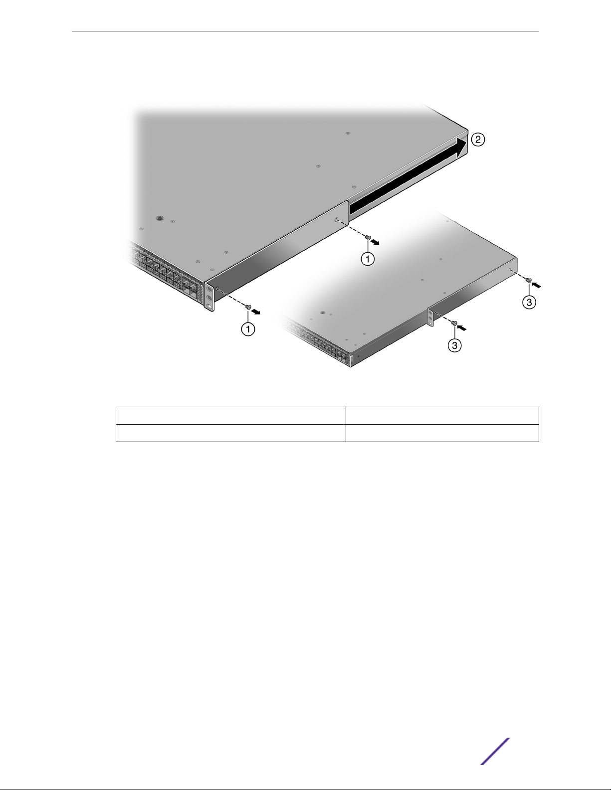
1 Unscrew the two rack mount ear screws as shown by callout 1, Figure 7 on page 19.
2 Reposition the rack mount ear, shown by callout 2, with the middle and power supply side screw
holes.
3 Reinsert the two rack mount ear screws, shown by callout 3.
S-Series Stand Alone (SSA) Switch Hardware Installation Guide 18
4 Repeat step 1 through step 3 on the other side of the chassis.
Installation
Figure 7: Mid-Mount I/O Ports Facing Front Configuration
1 = Ear mount screw removal
2 = Repositioning of rack mount ear
3 = Ear mount screw insertion
Mid-Mount Configuration with Power Supply Facing Front
The mid-mount, power supply facing front, configuration is depicted in callout 4, Figure 3 on page 13.
This rack mount configuration requires repositioning the rack mount ears on both sides of the device.
To reposition the rack mount ears for this configuration, follow these steps:
1 Unscrew the two rack mount ear screws as shown by callout 1, Figure 8 on page 20.
2 Reposition the rack mount ear towards the power supply end of the device, shown by callout 2 and
the thick black arrow.
The three-holed ear is now located in the middle of the device, facing the power supply side.
3 Reinsert the two rack mount ear screws, shown by callout 3.
S-Series Stand Alone (SSA) Switch Hardware Installation Guide 19
4 Repeat step 1 through step 3 on the other side of the chassis.
Installation
Figure 8: Mid-Mount Power Supply Front Configuration
1 = Ear mount screw removal
2 = Repositioning of rack mount ear
Securing the SSA Switch to the Rack
Warning
Before rack-mounting the device, ensure that the rack can support it without compromising
stability. Otherwise, personal injury and/or equipment damage may result.
Advertencia: Antes de montar el equipo en el rack, asegurarse que el rack puede soportar su
peso sin comprometer su propia estabilidad, de otra forma, daño personal o del equipo puede
ocurrir.
Warnhinweis: Überzeugen Sie sich vor dem Einbau des Gerätes in das Rack von dessen
Stabilität, ansonsten könnten Personenschäden oder Schäden am Gerät die Folge sein.
Avertissements: Avant de monter l'appareil sur le bâti, assurez-vous que l'étagère peut en
supporter le poids sans en compromettre la stabilité. Cela pourrait, dans le cas contraire,
entraîner des blessures ou des dommages au matériel.
3 = Ear mount screw insertion
S-Series Stand Alone (SSA) Switch Hardware Installation Guide 20
Installation
Note
The rack mounting ear provides three holes for securing the SSA switch to the rack. Use at
•
least two screws or fasteners appropriate to your rack on each side when securing the SSA
switch to the rack.
We recommend that power supplies be installed after the SSA switch has been secured to
•
the rack to minimize weight that must be supported when installing rack screws
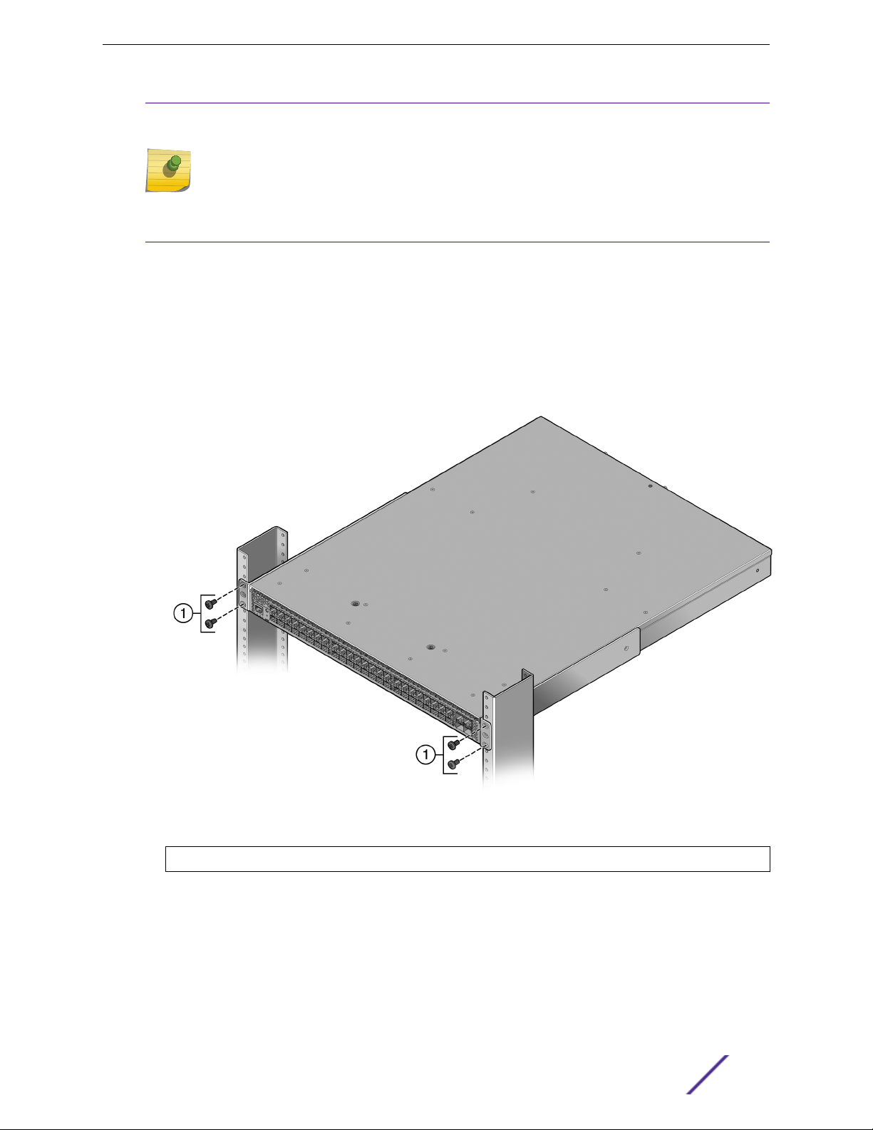
To secure the SSA switch to the rack, follow these steps:
1 Ensure that the rack mount ears are properly installed based upon the discussion in Rack Mount Ear
Positioning on page 17.
2 Align the rack mount ear holes with the front rack post holes in either a flush (Figure 9) or mid-
mount (Figure 10 on page 22) configuration.
3 Secure the SSA switch to each rack post with at least two screws or fasteners appropriate to the
rack as shown in callout 1 of the appropriate figure (Figure 9 or Figure 10 on page 22).
Figure 9: Securing the SSA Switch to the Rack in a Flush Mount Configuration
1 = 4 to 6 screws or fasteners appropriate to the rack
S-Series Stand Alone (SSA) Switch Hardware Installation Guide 21
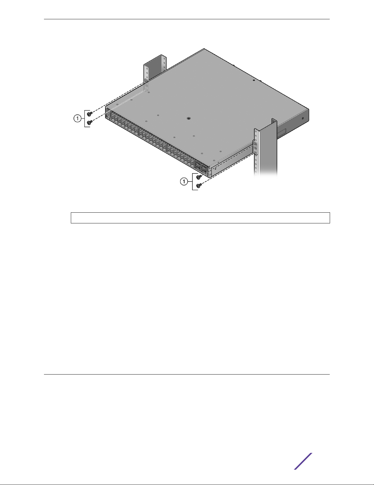
Installation
Figure 10: Securing the SSA Switch to the Rack in a Mid-Mount Configuration
1 = 4 to 6 screws or fasteners appropriate to the rack
You can now unpack and install the SSA power supplies. See
22.
Unpacking the Power Supplies on page
Installing the SSA Switch on a Flat Surface
For flat surface installation, optionally attach the adhesive rubber feet to the bottom of the SSA switch.
To attach the rubber feet to the bottom of the SSA switch, follow these steps:
1 Place the SSA switch upside down on a sturdy, flat surface.
2 Remove the adhesive backing from the four rubber feet.
3 Adhere the rubber feet to the round, recessed areas on the bottom of the SSA switch.
4 Turn the SSA switch rightside up.
You can now unpack and install the SSA power supplies. See Unpacking the Power Supplies on page
22.
Unpacking the Power Supplies
The SSA-FB-AC-PS-A and SSA-FB-AC-PS-B power supply modules are shipped in boxes separate from
the SSA switch.
To unpack a power supply, follow these steps:
1 Remove the power supply from the shipping box and slide the two foam end caps o the unit.
Save the shipping box and materials in case the unit must be reshipped.
S-Series Stand Alone (SSA) Switch Hardware Installation Guide 22
2 Verify the contents of the box using Table 6.
3 Remove the power supply from its protective plastic bag.
4 Examine the power supply carefully, checking for damage.
If there are any signs of damage, do not install the power supply; instead, contact us
Table 6: Contents of SSA Power Supply Carton
Item Quantity
Power supply (SSA-FB-AC-PS-A or SSA-FB-AC-PS-B) 1
Installation
For USA shipments: NEMA Power Cord 6-20, C19, R/A, SHLD
Type of power cord is dependent on country of installation.
Installing the Power Supplies
If you are installing only one power supply, you must put the power supply in the left power supply bay
(labeled PS1). The SSA switch ships without a coverplate for the PS1 bay.
Note
For proper operation, the SSA switch must have a power supply in PS1 whenever the SSA
switch is powered up.
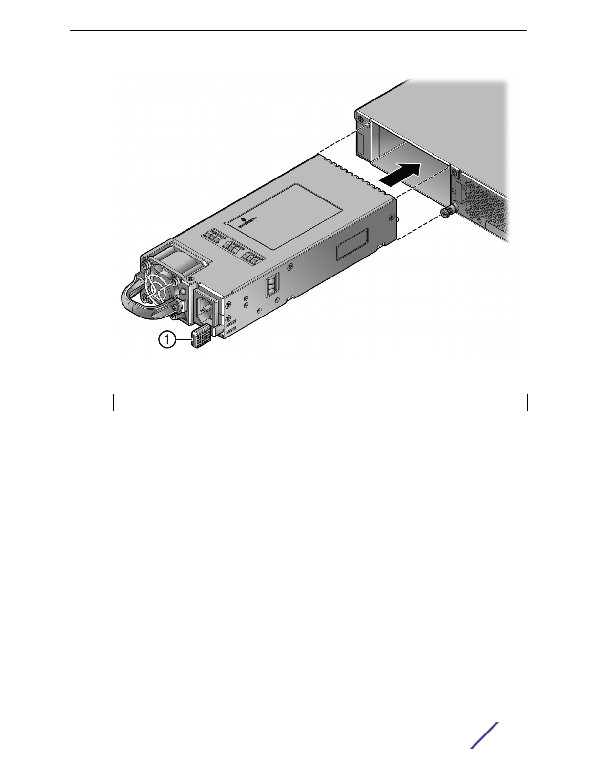
To install the power supplies in the SSA switch, follow these steps:
1 Use appropriate antistatic protection when handling power supplies.
2 Visually verify that the power supply airflow direction agrees with the airflow direction of the
installed fan module.
For details, see Power Supply Airflow and Switch Fan Module Airflow on page 14.
3 Holding the power supply by the handle and bottom, align the power supply with the left power
supply bay (labeled PS1).
4 Slide the power supply forward until it is plugged into the chassis connector and the lock tab clicks
to the right.
Pull on the power supply handle to ensure that the power supply is firmly in place. See Figure 11.
1
S-Series Stand Alone (SSA) Switch Hardware Installation Guide 23
Installation
Figure 11: Installing a Power Supply
1 = Lock Tab
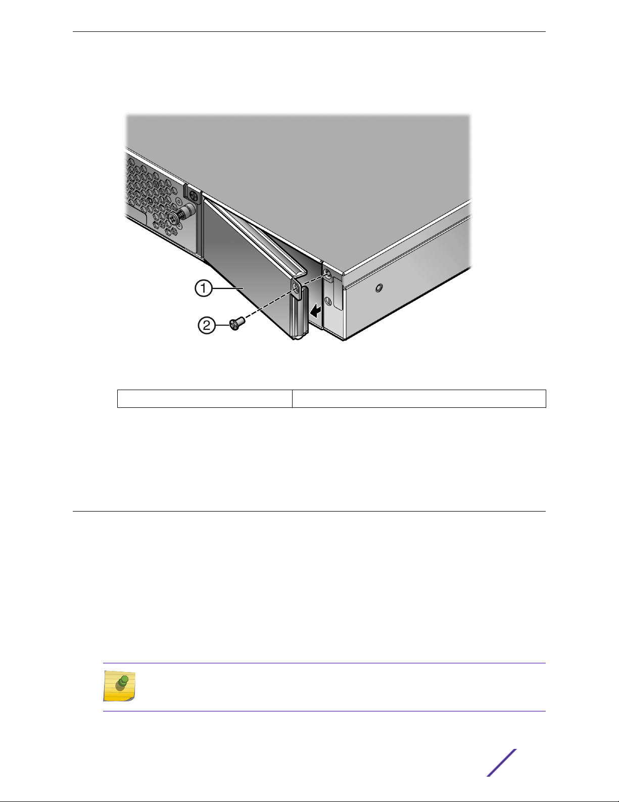
5 If you are installing a second power supply, remove the coverplate from the right power supply bay
by unscrewing the screw that attaches the coverplate to the SSA switch and rotating the coverplate
S-Series Stand Alone (SSA) Switch Hardware Installation Guide 24
Installation
out of its position from right to left before disengaging it from the chassis (see Figure 12). Reinstall
the screw after the cover plate is removed.
Figure 12: Removing the Power Supply Bay Coverplate
1 = Coverplate
Keep the coverplate in case you need to revert to a single power supply configuration. If a power
supply is not installed, the coverplate must be in place for proper airflow.
6 Repeat step 2 on page 23 through step 4 on page 23 to install the power supply in the right power
supply bay.
2 = Coverplate screw
Powering Up the SSA Switch
To connect the SSA switch to the power sources, follow these steps:
1 Plug a power cord into each power supply’s AC power receptacle.
2 Plug the cord into a dedicated grounded AC outlet.
In the case of a two power supply configuration, to take advantage of redundancy capabilities, plug
each power cord into a separate dedicated AC outlet.
The system PWR LED, located on the switch I/O port panel, turns ON (green) and the CPU LED turns
red until the SSA switch completes its initialization.
It takes less than 30 seconds for the SSA switch to boot up.
Note
If the power-up sequence is interrupted on the SSA switch, it might run an extended
diagnostics sequence that takes up to two minutes to complete.
S-Series Stand Alone (SSA) Switch Hardware Installation Guide 25
When the initialization process is successful, the CPU LED turns green. If the CPU LED does not turn
green, refer to Troubleshooting on page 34.
Installing the Power Cord Retention Clip Assembly
The SSA switch comes with two optional power cord retention clip assemblies. Power cord retention
clips provide added security against the inadvertent removal of the power cord from the power supply
AC receptacle.
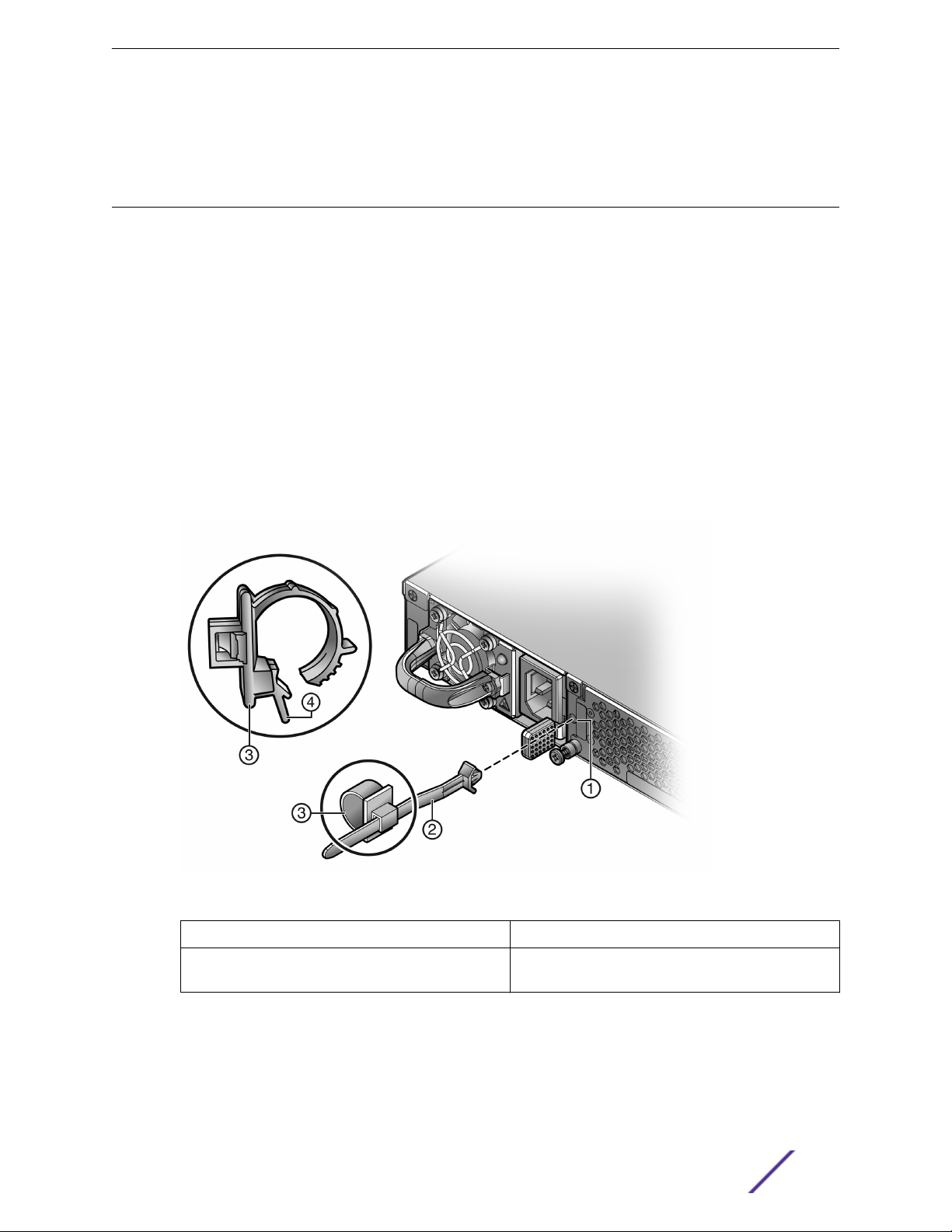
To install the power cord retention clip assembly, follow these steps:
1 Holding the strap piece with the rough side facing away from the power supply, shown by callout 2
of Figure 13 on page 26, insert the strap piece into the hole to the right of the power cord
receptacle, shown by callout 1.
2 Slide the power cable clamp, shown by callout 3, onto the strap piece with the tab on the clamp
piece facing out.
3 Insert the power cord in the open clamp.
4 Close the clamp piece.
To open the clamp piece, push down the clamp release tab, shown by callout 4.
Installation
Figure 13: Installing the Power Cord Clip Assembly in the Power Supply
1 = Retention clip receptacle
2 = Retention clip strap piece, smooth side facing
power supply
S-Series Stand Alone (SSA) Switch Hardware Installation Guide 26
3 = Power cable clamp
4 = Clamp release tab
 Loading...