

Extreme Networks NG300, Sentriant NG Installation Manual

Sentriant NG Installation Guide
Extreme Networks, Inc.
3585 Monroe Street
Santa Clara, California 95051
(888) 257-3000
(408) 579-2800
http://www.extremenetworks.com
Published: January 2008
Part number: 100288-00 Rev. 01

AccessAdapt, Alpine, Altitude, BlackDiamond, EPICenter, ESRP, Ethernet Everywhere, Extreme Enabled, Extreme
Ethernet Everywhere, Extreme Networks, Extreme Standby Router Protocol, Extreme Turbodrive, Extreme Velocity,
ExtremeWare, ExtremeWorks, Essentials, ExtremeXOS, the Go Purple Extreme Solution, ScreenPlay, Sentriant,
ServiceWatch, Summit, SummitStack, Triumph, Unified Access Architecture, Unified Access RF Manager, UniStack,
the Extreme Networks logo, the Alpine logo, the BlackDiamond logo, the Extreme Turbodrive logo, the Summit
logos, the Powered by ExtremeXOS logo, and the Color Purple, among others, are trademarks or registered
trademarks of Extreme Networks, Inc. or its subsidiaries in the United States and/or other countries.
Adobe, Flash, and Macromedia are registered trademarks of Adobe Systems Incorporated in the U.S. and/or other
countries. AutoCell is a trademark of AutoCell. Avaya is a trademark of Avaya, Inc. Internet Explorer is a registered
trademark of Microsoft Corporation. Mozilla Firefox is a registered trademark of the Mozilla Foundation. sFlow is a
registered trademark of sFlow.org. Solaris and Java are trademarks of Sun Microsystems, Inc. in the U.S. and other
countries.
Specifications are subject to change without notice.
All other registered trademarks, trademarks, and service marks are property of their respective owners.
© 2007-2008 Extreme Networks, Inc. All Rights Reserved.
Sentriant NG Installation Guide2

Table of Contents
Table of Contents
Preface........................................................................................................................................... 5
About this Guide .........................................................................................................................5
Organization of this Guide ............................................................................................................5
Conventions ................................................................................................................................5
Related Publications ...................................................................................................................6
Chapter 1: About the Sentriant NG Appliance .................................................................................... 7
Chassis Overview.........................................................................................................................7
Front Panel Features ...................................................................................................................7
Back Panel Features....................................................................................................................8
LED Operation ............................................................................................................................8
Chapter 2: Site Preparation and Unpacking ...................................................................................... 9
Site Requirements for the Sentriant NG Appliance .........................................................................9
Rack Ventilation Requirements ...............................................................................................9
Unpacking the Sentriant NG Appliance .......................................................................................10
Package Contents................................................................................................................10
Chapter 3: Installing the Sentriant NG Appliance............................................................................. 11
Overview ..................................................................................................................................11
Required Tools and Equipment...................................................................................................12
Attaching the Mounting Brackets ................................................................................................12
Installing the Sentriant NG Appliance in a Rack...........................................................................13
Connecting Power .....................................................................................................................13
Connecting Cables ....................................................................................................................14
Configuring the Switch ..............................................................................................................14
Chapter 4: Start-Up and Initial Configuration...................................................................................17
Requirements Before the Initial Setup.........................................................................................17
Initial Configuration Using the Serial Port ....................................................................................17
Navigating in the Text User Interface ....................................................................................18
Power-On and System Boot ..................................................................................................18
Installing the Sentriant NG Manager Software ..............................................................................23
Starting and Logging In To Sentriant NG Manager ..................................................................23
Using the Online Help System ..............................................................................................24
Appendix A: Safety Information ...................................................................................................... 25
Considerations Before Installing .................................................................................................25
Power Safety ............................................................................................................................25
Maintenance Safety...................................................................................................................26
General Safety Precautions ........................................................................................................26
Battery Replacement and Disposal..............................................................................................27
Sentriant NG Installation Guide 3

Table of Contents
Appendix B: Technical Specifications ............................................................................................31
Specifications ...........................................................................................................................31
FCC Class A Notice ...................................................................................................................33
User Information .................................................................................................................33
ICES-003 Class A Notice ...........................................................................................................34
Index............................................................................................................................................ 35
Sentriant NG Installation Guide4

Preface
This preface provides an overview of this guide, describes guide conventions, and lists other
publications that might be useful.
About this Guide
The Sentriant NG Installation Guide describes how to install and connect the Sentriant NG appliance and
perform required initial configuration.
This guide is intended for use by system and network administrators and by trained, qualified network
installation and support technicians who are responsible for installing and setting up network
equipment. This guide assumes a working knowledge of:
● Ethernet technology and terminology as it applies to local area network (LAN) access
● Safety practices when working with electrical equipment.
Organization of this Guide
This guide includes the following chapters and appendixes:
● Chapter 1, “About the Sentriant NG Appliance”
● Chapter 2, “Site Preparation and Unpacking”
● Chapter 3, “Installing the Sentriant NG Appliance”
● Chapter 4, “Start-Up and Initial Configuration”
● Appendix A, “Safety Information”
● Appendix B, “Technical Specifications”
Conventions
Ta bl e 1 and Tab le 2 list conventions used in Extreme Networks customer documentation.
Table 1: Notice Icons
Icon Notice Type Alerts you to...
Note Important information, helpful suggestions, or reference material.
Caution Risk of personal injury, system damage, or loss of data.
Warning Risk of severe personal injury.
Sentriant NG Installation Guide 5

Preface
Table 2: Text Conventions
Convention Description
Screen displays or
entered text
The words “enter”
and “type”
<Key> names Key names appear in text in one of two ways:
Words in italicized type Italics emphasize a point of information or denote new terms at the place where
Bold type Graphical user interface (GUI) names and control options that appear on the
This typeface represents information as it appears on the screen, command syntax,
or text you enter on a command line.
When you see the word “enter” in this guide, you must type something, and then
press the Return or Enter key. Do not press the Return or Enter key when an
instruction simply says “type.”
• Referenced by their labels, such as “the Return key” or “the Escape key”
• Written with angle brackets, such as <Enter> or <Esc>
If you must press two or more keys simultaneously, the key names are linked with a
plus sign (+). Example:
Press <Ctrl> + <Alt> +< Del>.
they are defined in the text.
management screen.
Related Publications
For more information about configuring and using the Sentriant NG appliance, refer to the following
publications:
●
Sentriant NG Operation Console User Guide
●
Sentriant NG Manager User Guide
●
Sentriant Rules Guide
Documentation for Extreme Networks products is available from the Extreme Networks website at the
following location:
http://www.extremenetworks.com/services/documentation
Sentriant NG Installation Guide6
1 About the Sentriant NG Appliance
This chapter includes the following sections:
● Chassis Overview on page 7
● Front Panel Features on page 7
● Back Panel Features on page 8
● LED Operation on page 8
Chassis Overview
The Sentriant NG appliance is a compact enclosure that is 2 RU (3.5 inches) high. It fits into a standard
19-inch (48.26 cm) rack. The Sentriant NG appliance provides four Gigabit Ethernet
detection/mitigation ports, a Gigabit Ethernet management port, a console port, and two USB ports.
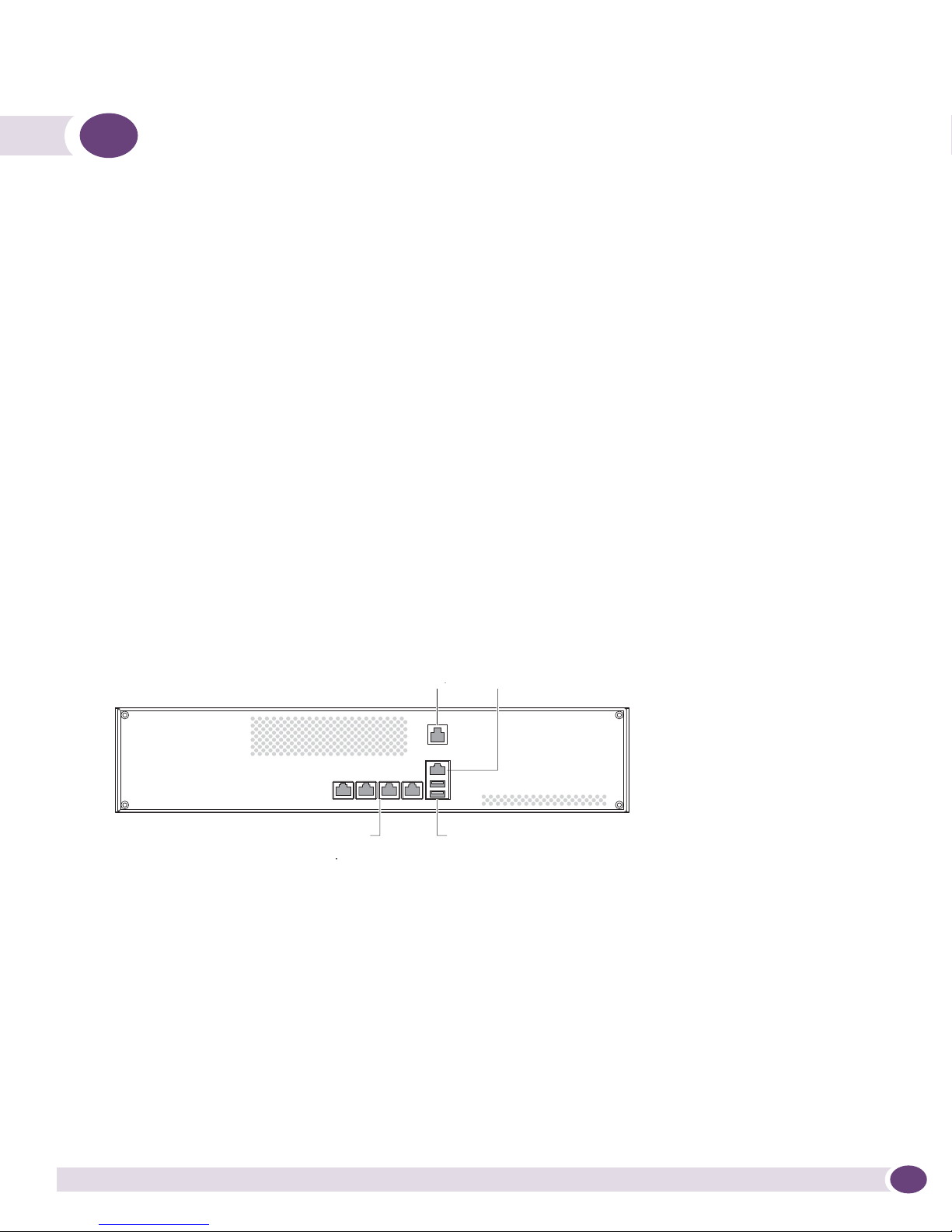
Front Panel Features
Figure 1 shows the front panel of the Sentriant NG appliance.
Figure 1: Front Panel Features
Ethernet
management port
USB ports
NG300_front
Detection/mitigation
Detection/Mitigation
ports
ports
Serial console
port
Serial port
The front panel of the Sentriant NG appliance has the following ports:
● Ethernet management port—Connects the Sentriant NG appliance through an Ethernet cable to the
I/O port of a switch. Use this port to manage the Sentriant NG appliance. Detection and mitigation
of threats are not performed on the management port.
● Serial console port—Connects the Sentriant NG appliance to a terminal. Use this port to perform
initial configuration and maintenance of the Sentriant NG appliance. Connect this port using the
provided DB-9F-to-RJ-45 cable.
● 10/100/1000 Base-T Ethernet detection/mitigation ports—Connect these ports to the switch ports
that will be monitored by the Sentriant NG appliance.
● USB ports—Used for technical support only. Do not insert any device into these ports unless
instructed by an Extreme Networks technician.
Sentriant NG Installation Guide 7
About the Sentriant NG Appliance
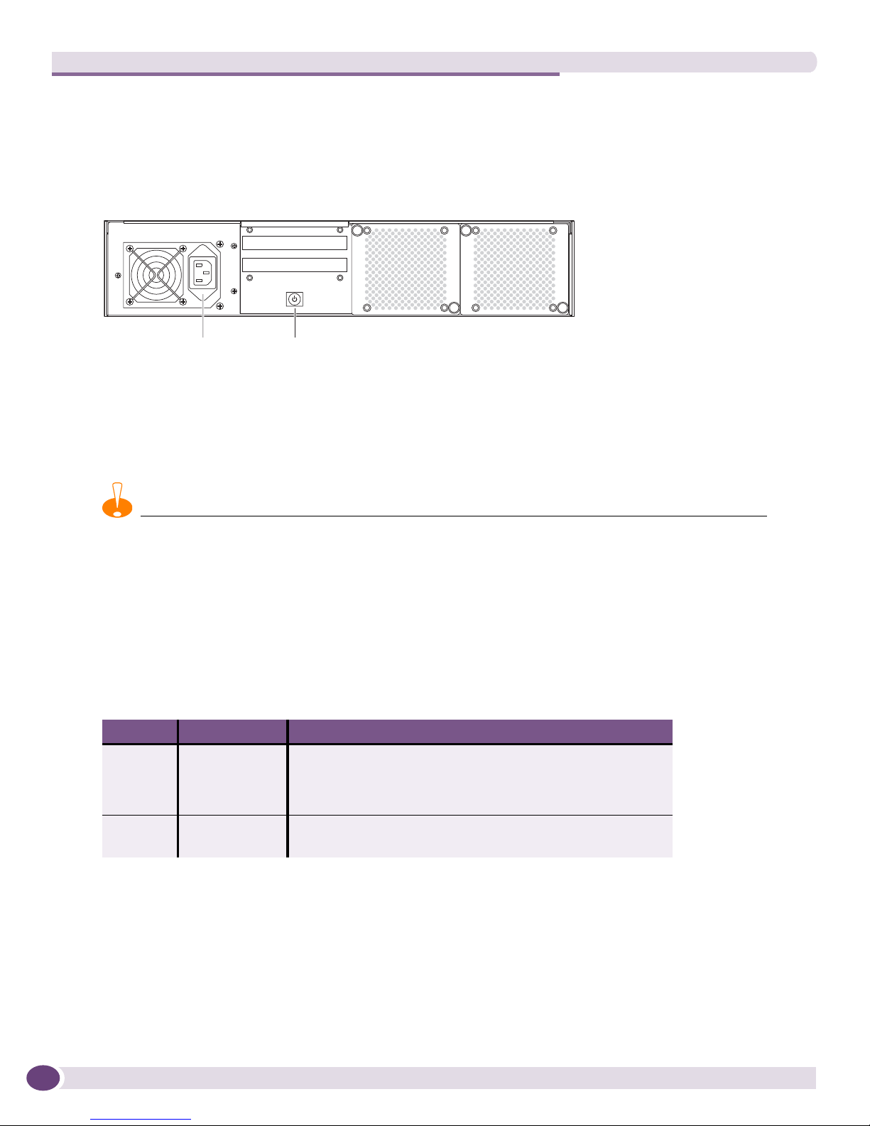
Back Panel Features
Figure 2 shows the back panel of the Sentriant NG appliance.
Figure 2: Back Panel Features
AC power
connector
Powe r
switch
NG300_back
The back panel of the Sentriant NG appliance has the following features:
● AC power connector
● Power switch
CAUTION
After the Sentriant NG appliance is powered on, do NOT shut down the unit by pressing the power switch. Shutting
down the unit should be done only through Sentriant NG Manager. See the Sentriant NG User Guide for details.
LED Operation
The detection/mitigation ports and the Ethernet management port have integrated link and activity
LEDs to indicate operating status. Tab le 1 describes the LED meanings.
Table 1: LED Meanings
LED Type Activity Meaning
Link
(Left)
Activity
(Right)
Steady green A 1000-Mbps link is detected and connected.
(Because the Ethernet management port operates at 10/100
Mbps only, it should never show a green link.)
Steady amber A 100-Mbps link is detected and connected.
Steady green No activity
Blinking green Activity
Sentriant NG Installation Guide8

2 Site Preparation and Unpacking
This chapter includes the following sections:
● Site Requirements for the Sentriant NG Appliance on page 9
● Unpacking the Sentriant NG Appliance on page 10
Site Requirements for the Sentriant NG Appliance
The Sentriant NG appliance can be rack-mounted in a standard 19-inch rack.
Be sure to locate the system away from heat sources and in an area that provides unobstructed air flow
to the chassis cooling vents. The chassis intake ambient air temperature should not exceed 95 ºF (35 ºC)
or drop below 41ºF (5º C).
CAUTION
Do not place a monitor or other object on top of the system. The mounting brackets and chassis cover are not
designed to support additional weight.
Make sure that the voltage and frequency of the power source matches the electrical ratings of the
Sentriant NG appliance, and that the building and/or power source provides overload protection.
In regions that are susceptible to electrical storms, we recommend that you plug your system into a
surge suppressor.
Rack Ventilation Requirements
● Make sure that there is a minimum of 3 inches of airspace at the back of the chassis.
● Open-type racks should meet the manufacturer’s recommended ventilation requirements.
● Enclosed-type racks should have a louvered front and back with a fan to dissipate heat generated by
equipment mounted in the rack.
● If you are installing the Sentriant NG appliance in enclosed racks with top-mounted ventilation fans,
make sure that there is adequate ventilation for the racks. Heat generated by equipment mounted in
the bottom of the rack can be drawn up into equipment mounted in the top of the rack.
● Chassis intake ambient air temperature should not exceed 95º F (35º C).
● Operating humidity should be kept between 10% and 95% relative humidity (noncondensing).
Sentriant NG Installation Guide 9

Site Preparation and Unpacking
Unpacking the Sentriant NG Appliance
Do not unpack the Sentriant NG appliance until you are ready to install it. Storing the chassis in its
shipping container helps protect it from accidental damage.
Package Contents
When you unpack the shipping container, confirm that you received the following items:
● Extreme Networks Sentriant NG appliance
● Bracket mounting kit:
■ Screws, #6-32 x 1/4-inch (qty. 8)
■ L-shaped mounting brackets (qty. 2)
● AC power cord for use in North America
● DB-9F to RJ-45 console cable
● CD containing
■ Sentriant NG Manager Installer for Windows
■ XML files for IPTel rules
■ XML file of Names Sets exclusions
■ Sentriant NG Manager Installer for MAC OS (unsupported)
■ Sentriant NG Installation Guide
■
Sentriant NG Manager User Guide
■
Sentriant Rules Guide
● CD containing
■ Sentriant NG Operations Console installer for Windows
■
Sentriant NG Operation Console Users Guide
●
Sentriant NG Appliance Quick Start Guide
● Software License Agreement
● Registration card
Sentriant NG Installation Guide10

3 Installing the Sentriant NG Appliance
This chapter includes the following sections:
● Overview on page 11
● Required Tools and Equipment on page 12
● Attaching the Mounting Brackets on page 12
● Installing the Sentriant NG Appliance in a Rack on page 13
● Connecting Power on page 13
● Connecting Cables on page 14
● Configuring the Switch on page 14
Overview
The Sentriant NG appliance fits into a standard 19-inch (48.26 cm) rack.
Carefully read all cautions and warnings before beginning the installation.
CAUTION
The Sentriant weighs approximately 40 pounds (18 kilograms). To reduce the risk of personal injury, do not attempt
to install the system in a rack by yourself.
CAUTION
The Sentriant rack installation procedures should be performed by trained service technicians.
CAUTION
Do not place a monitor or other object on top of the Sentriant chassis. The chassis bracket hardware is not designed
to support the additional weight of objects other than the Sentriant chassis.
WARNING!
If you are installing more than one Sentriant in a rack, always install the first Sentriant in the lowest available
position in the rack. Installing a Sentriant in a high position in the rack first could cause the rack to tip over.
Sentriant NG Installation Guide 11
 Loading...