

Extreme Networks Px Series, SummitPx1, PxM Installation And Configuration Manual

Px Series
Application Switch
Installation and
Configuration Guide
Extr eme N et work s, In c.
3585 Monroe Street
Santa Clara, California 95051
(888) 257-3000
http://www.extremenetworks.com
Published: April 200 2
Part number : 100101-00 Rev. 02

©2002 Extre me N etw orks , In c. A ll ri gh ts re ser ved. E xt reme N etw or ks an d Bl ack Diam ond are
registered trademarks of Extreme Networks, Inc. in the United States and certain other jurisdictions.
Extrem eWare, Extre meWare Vista, Ext remeWorks, Ext remeA ssi st, Extre meA ssi st1, Ext rem eAs sist2 ,
PartnerAss ist, E xtreme S tandb y Route r Proto col, ESR P, SmartTraps, Alpine, Summ it, Sum mit1,
Summit4, Summit4/FX, Summit7i, Summit24, Summit48, Summit Virtual Chassis, SummitLink,
Summi tGbX , Su mmi tPx 1, Su mmi tR PS an d the Ext reme Ne twor ks l ogo are trad emar ks o f E xtrem e
Netwo rks , Inc ., w hich may be re gis tered or p end ing reg ist rati on in ce rta in ju ri sdict ion s. T he Ex treme
Turbodrive l ogo is a s erv ice mar k of Extre me N etw orks , whi ch may b e re gis tered or p endi ng
registration in certain jurisdictions. Specifications are subject to change without notice.
NetWare and Novell are registered trademarks of Novell, Inc. Merit is a registered trademark of Merit
Netwo rk, Inc. Sola ris is a tra dem ark o f Su n Mi crosy ste ms, Inc. F5, BIG /i p, an d 3D NS are regi st ered
tradem ar ks of F5 N et work s, I nc. s ee /IT is a trad em ark o f F5 N e twor ks, Inc.
All other registered trademarks, trademarks and service marks are property of their respective owners.
II

Contents
Preface
Introduction 1-vii
Conventions 1-viii
Related Publications 1-ix
1 Server Load Balancing Concepts
Purpose of Server Load Balancing 1-1
Terms 1-2
Load Balancing Modes 1-3
Laye r 4 L oad Bala nci ng 1-3
Layer 7 Load Balanc ing and Content Ana lysis 1-4
Port Rewrite 1-6
Getting Started on Load Balancing Configuration 1-6
2 Installing the SummitPx1 Application Switch
Overview of the SummitPx1 Application Switch 2-1
SummitPx1 Front View 2-1
SummitPx1 A pplication Sw itch Rear View 2-3
Determining the Location 2-4
Installing the SummitPx1 Application Switch 2-4
Rack Mounting 2-4
Px Series Ap plication Switc h Installa tion and Co nfiguration Gui de iii

Free-Standing 2-5
Powering On the Summit Px1 2-5
Setting Up Console Communication 2-6
Configuring Switch IP Parameter s 2-7
Configuring the 10/100 Ethernet Management Port 2-8
3 Installing the PxM Application Switch Module
Installing I/O Modules 3-1
Removing I/O Mo dules 3-2
4 Managing the Switch
Using the Command-Line Interface 4-2
Abbreviate d Syntax and C ommand C omplet ion 4-2
Syntax Symbols 4-2
Line-Editing K eys 4-3
Specifying Text Values 4-3
Command History 4-4
Prompt Text 4-4
Config uring Man agemen t Access 4-4
Changing the Default Passwords 4-5
Creating Ac count s 4-6
Managing the PxM 4-7
Configuring VLANs 4-8
Configuri ng SNM P 4-9
Configuri ng DNS Client Services 4-10
Using Secure Shell 2 (SSH2) 4-11
Enabling SSH2 for Inbound Switch Access 4-12
Using SCP2 from an External SSH2 Client 4-13
SSH2 Client Functions on the Switch 4-14
Utilities 4-15
Showing CPU Load 4-15
Checking Basic Connectivity 4-15
Logging 4-16
iv Px Series Application Switc h Installation a nd Con figuration Guid e

Configuring a Startup Banner Message 4-17
Starting the GlobalPx Content Director Agent 4-17
Example Configuration 4-18
5 Configuring Servers and Services
Configuring Real Servers 5-1
Configuri ng Server G roups 5-2
Configuri ng Virtual Servic es 5-3
Layer 4 Port-based Load Balancing 5-4
Layer 7 Virtual Services 5-4
Configuring Traffic Tagging 5-5
Configura tion Ex ample 5-6
6 Choosing Policies, Persistence Modes, and NAT
Scheduling Policies 6-1
Persistence Modes 6-2
UDP Flow Pers istence 6-3
Client IP Persistenc e Mode 6-3
Cookie Persist ence Modes 6-5
SSL Session Identifier Persistence 6-13
NAT Modes 6-14
Configura tion Ex ample 6-17
7 URL Switching
Domain and URL Switching 7-1
Configuring URL Switching 7-4
Creating Domain and URL Switching Rules 7-8
Px Series Ap plication Switc h Installa tion and Co nfiguration Gui de v
Full-NAT Mode 6-14
Server-only Half-NAT Mode 6-15
Domain Switc hing 7-2
URL Switchi ng 7-4
Modifying Ex isting URL Rul es and Domain s 7-9

Configura tion Ex ample 7-9
8 Configuring Redundancy
Using VRRP with the SummitPx1 8-1
Adding an d Configurin g VRRPs 8-2
Using VRRP in Existing Red undant Netwo rks 8-3
VRRP Automatic Synchronization 8-4
Configuri ng Redu ndancy f or the PxM 8-6
Using ESRP wi th the PxM 8-6
Configuring the PxM for Mult iple VLANs 8-7
Configuring a Default Gateway 8-8
9 Health Checks
Overview 9-1
Server Startup Pacing 9-2
Health Checking Procedure 9-3
Configuring Health Checks 9-4
Types of Health Checks 9-4
Timers and C ounte rs 9- 4
10 Monitoring the Switch
Showing Traffic Statistics 10-1
Showing Configuration Details 10-3
Configuration Displays 10-4
Status Displays 10-5
Managing and Troubleshooting Operation 10-7
Index
Index of Commands
vi Px Series Application Sw itch Installati on and Con figuration Guid e

Preface
This preface provides an overview of this guide, describes guide conventions, and lists
other publicatio ns that may be u seful.
Introducti on
This guide provides the required information to configure the Extreme Networks Px
series applicat ion switches, Su mmitPx1
TM
and P xMTM.
This guide is intended for use by network administrators who are responsible for
installing and setting up network equipment. It assumes a basic working knowledge of:
• Local area ne tworks (L ANs)
• Ethernet concepts
• Ethernet sw itching and br idging conc epts
• Routing concepts
• Internet Protocol (IP) conc epts, including connection initiatio n process
• Netw ork A ddre ss Translat ion ( NAT)
If the information in the release notes shi pped with your switch differs from the
information in this guide, follow the release notes.
Px Series Ap plication Switc h Installa tion and Co nfiguration Gui de vii

Preface
Conventions
Table 1 and Table 2 list conven tions that are us ed throughout this guide.
Table 1: Notice Icons
Icon Notice Type Alerts you to...
Note Important features or instr uctions.
Caution Risk of personal injury, system damage, or loss of data.
Warning Risk of severe per sonal injury.
Table 2: Text Convent ions
Convention Description
Screen displays This typeface indicates command syntax, or represents information
as it appears on the screen.
The words “enter”
and “type”
[Key] names Key names are written with brackets , such as [Return] or [Esc].
Words in italicized type Italics emphasi ze a point or denote new terms at the place where
When you see the word “enter” in this guide, you must type
something, and then press the Return or Enter key. Do not press
the Return or Enter key when an instruction simply says “type.”
If you must press two or more keys simultaneously, the key names
are linked with a plus sign (+). Example:
Press [Ctr l]+[Alt ]+[Del].
they are defined in the text.
viii Px Series App lication Switc h Installation a nd Con figuration Guid e

Related Publications
Related Publications
The publica tions related t o this one are:
• ExtremeWare Software User G uide
• Px Series Application Switch Relea se Notes
Documentation for Extreme products is available on the World Wide Web at the
following loca tion:
• http://www.extremenetworks.com
Px Series Ap plication Switc h Installa tion and Co nfiguration Gui de ix

Preface
x Px Series Applicati on Switch Ins tallation a nd Configurati on Guide

1
Server Load Balancing Concepts
The Px series application switch marks the next step in server load balancing. Using a
revolutionary hardware des ign, the Px series ap plication switch is designed to help
website adm inistrators ac hieve levels of av ailability and s calability nev er before
possible.
This chapter cont ains the follow ing sections:
• Purpose of Server Load Balancing on page 1-1
• Load Balan cing Modes on p age 1- 3
• Port Rewrite on page 1-6
• Getting Started o n Load Bala ncing Configurati on on pag e 1-6
Purpose of Server Load Balancing
An applicati on switch in creases website availab ility by allow ing for web se rvers to fail
(or be shut down for maintenance) without a website outage. It also improves the
response times of the website and increases the traffic-handling capacity of the website
by allowing m ultiple servers to be used together as a single site.
Px Series Ap plication Switc h Installa tion and Co nfiguration Gui de 1-1
The Px series application switch can examine actual user requests, rather than simply
forwarding the requests to the servers. You can use the powerful array of tools provided
by the Px serie s application sw itch to scale webs ites by:
• Creating special purpose servers
• Making better use of web caches
• Allowing movem ent of web co ntent without extensiv e re-linking of the si te
Terms
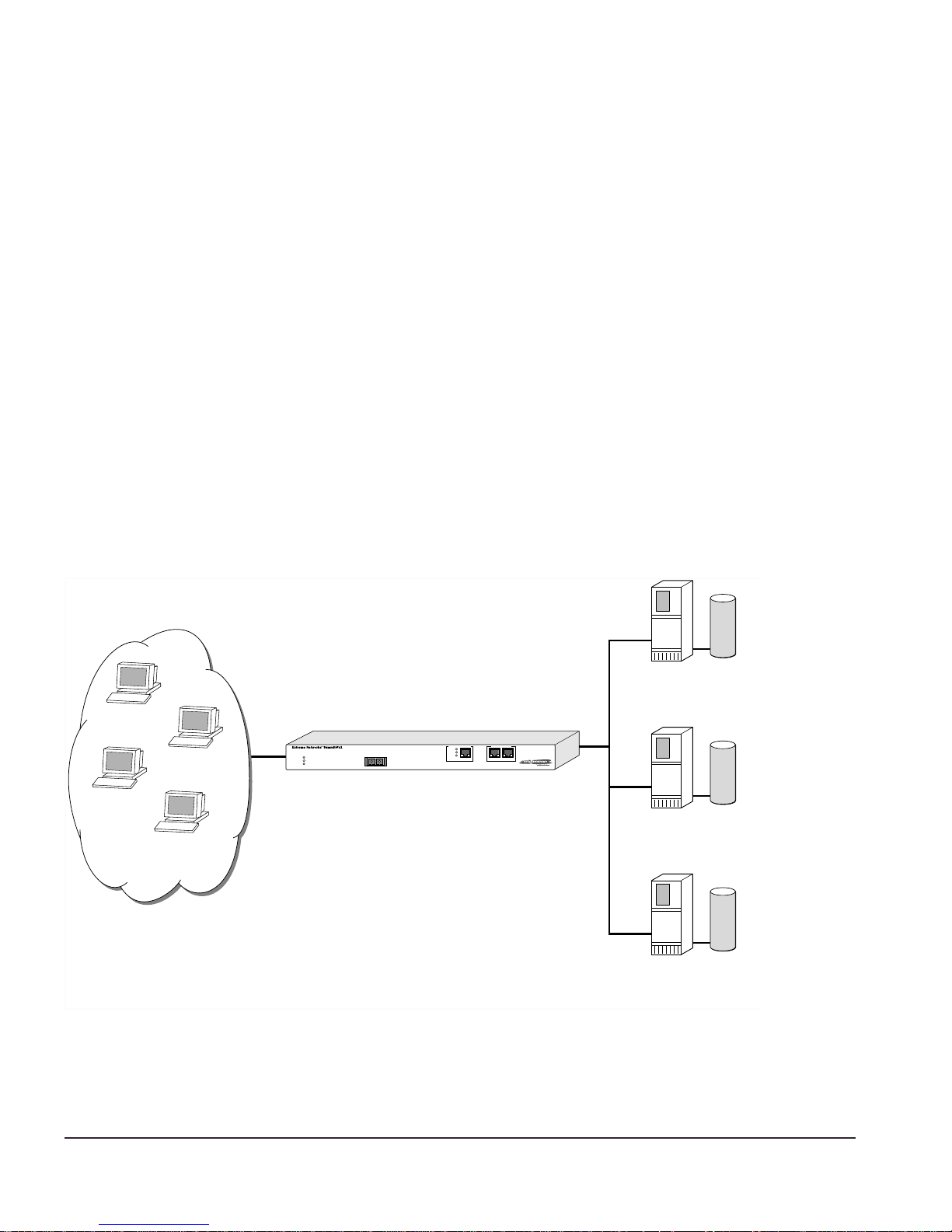
The Px series application switch creates a level of abstraction between the real servers
and the Internet, by configuring a virtual IP (VIP) address and port on the application
switch. The VIP has a globally-reachable public IP address, and corresponds to the DNS
entry for the w ebsite. All traffic for the website is se nt to the applicat ion switch, whic h
applies policies to decide how to forward the traffic to a real server.
Figure 1-1 shows several Internet users all co nnecting to the web site www.busy.com.
Virtual Server
101.1.35.2
235.19.10.1
193.16.1.36
64.64.6.4
www.busy.com
64.10.10.100
Internet clients
Figure 1-1: Conceptual view of server load balancing
Real Server 1
10.1.1.3
Real Server 2
10.1.1.4
Real Server 3
10.1.1.5
WS_012
1-2 Px Series Applicati on Switch Ins tallation a nd Configurati on Guide

Load Balancing M odes
In this document, the Internet users are referred to as clients, because they are clients of
the applicat ion switch. The website, w hich is actua lly an address inside the applic ation
switch, i s also c alled a vi rtual IP a ddress, or VIP. Because the Px series application switch
uses the unique combination of IP address and source port, the VIP is referre d to as a
virtual service.
Load Balancing Modes
The Px series application swi tch can perfor m packet redirection f or load balanc ing in
two different ways:
• Layer 4 load balancing
• Layer 7 load balancing
Layer 4 Lo ad Balan cing
In layer 4 mode, the applicat ion switch decid es which serve r should receive a giv en
user request using server selection policies. It selects a server without looking at the
content of the request. The following server selection policies are su pported by the Px
series applica tion switch :
• Round robin
• Weighte d round ro bin
• Least con nections
• We ighted least connect ions
For more information on policies, see Chapter 6.
The applic ation switch c an ba lance a lmost any traffic usin g networ k addres s trans lation
(NAT) at layer 4. The applicatio n switch rewrites the destina tion IP address of th e
request to point to the real server selected to handle the request, and sets the source IP
address of the request to point to one of the internal IP addresses of the Px series
application switch. When the server responds to the request, the application switch
rewrites the response so that it appears to originate from its VIP address, and forwards
the response to th e client.
Figure 1-2 illustrates a single client-server transaction using layer 4.
Px Series Ap plication Switc h Installa tion and Co nfiguration Gui de 1-3
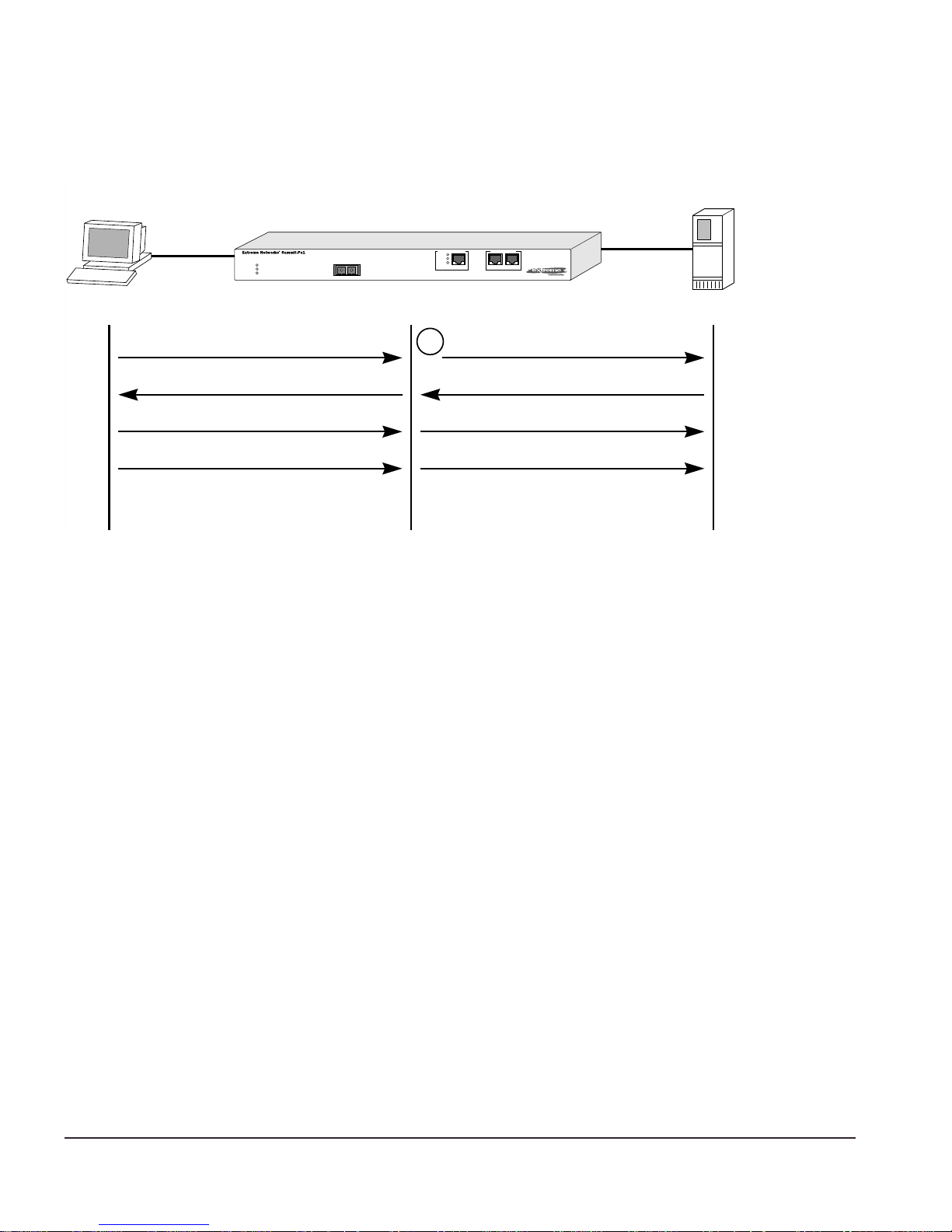
Client Real Server
SYN
1
SYN/ACK
ACK
DATA
(http request)
WS_013
Figure 1-2: Single client-server transaction using layer 4
As soon as th e first request from the client is received at the application s witch, the
application switch uses the server-selection policy configured for the VIP to select the
server and immediately sends out the NAT-ed request to the real server. The client and
server continue the connection establishment pro tocol using the application switch in
the middle, NAT-ing the traffic. After the connection is established, an HTTP request is
sent and th e server responds.
Layer 7 Load Balancing and Content Analysis
To make server-selection decisions based on cookies or the URL being requested by the
client, the appl ication sw itch must actu ally look ins ide the clie nt request. Becau se this
data request is only sent out after a connection is established, the Px series application
switch must first act as a proxy for the server by acting as the endpoint of the TCP/IP
connection from the c lient. This proce ss is called layer 7 load balancing.
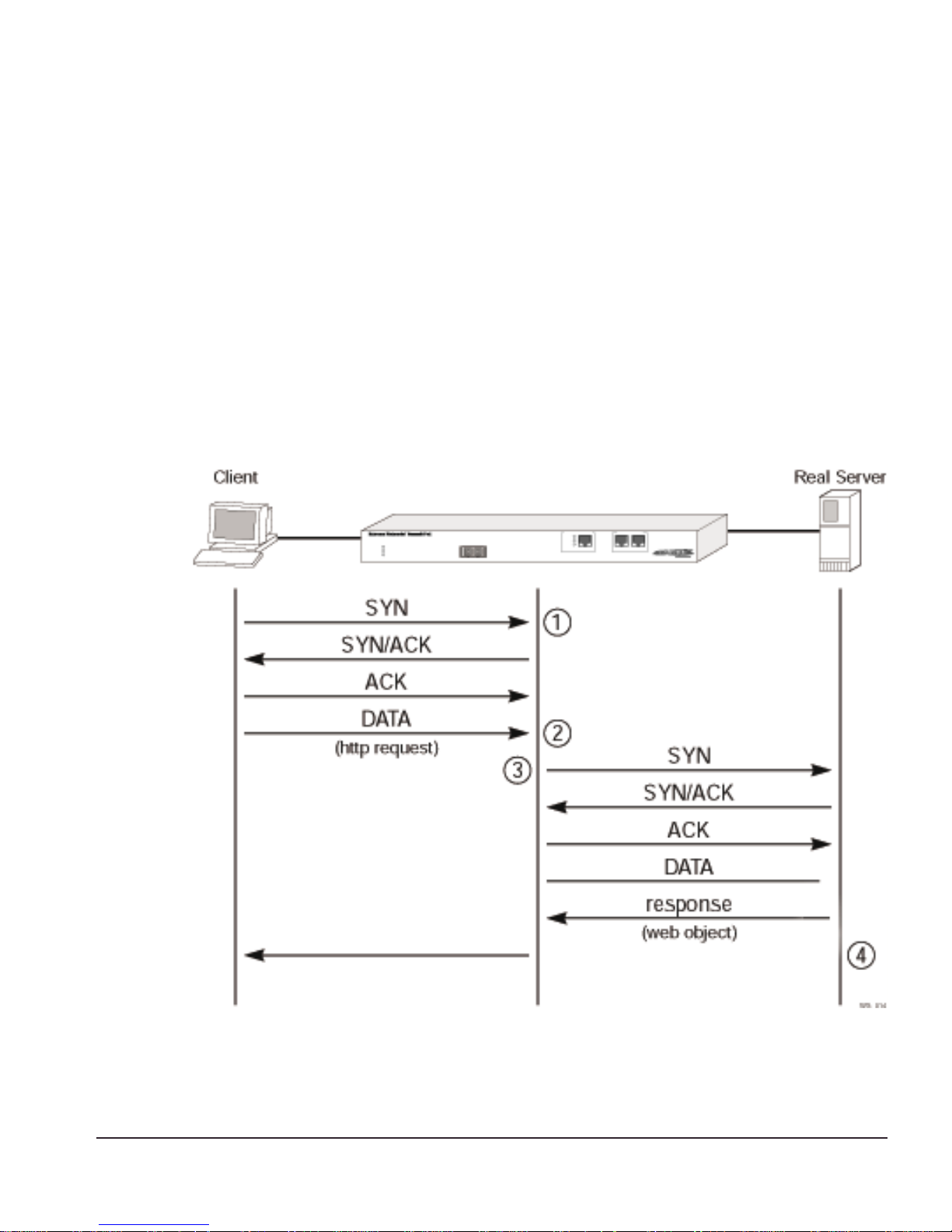
The Px series application switch delays the establishment of a connection to a server
until the firs t 1500 bytes of actual data (the HTTP request) is received from the client.
The application switch then takes the content being requested, along with the domain to
which the request pertains, and applies policy rules. Based on the outcome of the policy
decision, the application swit ch establishes a T CP connection w ith the real server
1-4 Px Series Applicati on Switch Ins tallation a nd Configurati on Guide
Load Balancing M odes
chosen to process the request, using a source IP address that is part of a proxy pool
inside the ap plication sw itch.
After a connection is established between the appl ication switch and the real server, the
application switch forwards the buffered data to the server. The server sends any
response to the a pplication switch . The applicat ion switch t ranslates th e IP source
address and port numbers appropriately, along with the TCP sequence and
acknowledgment numbers, and then forwards the data to the real client on the Internet.
Return traffic from the real server does not require content analysis, and is simply
rewritten by the NAT engine.
Figure 3 illustrates t he sequence used to establish a laye r 7 request.
Figure 1-3: Establishing a layer 7 request
Px Series Ap plication Switc h Installa tion and Co nfiguration Gui de 1-5

Por t Rewrite
When a request is sent by a client to a VIP service, the request contains the well-known
port number for the requested application. For example, the well-known port number
for HTTP is port 80.
You can configure the application switch to rew rite the port, configuring a server group
to use a specific port, other than the well-known port number for the application. Port
rewrite is useful in ins tances where multi ple dom ains are configured on the same server
(or all servers in the same server group) an d each domain has its own server process.
By giving each domain its own port number, each server process can be configured to
listen for requ est s at it s own p ort.
Getting Star ted on Load Balancing Configuration
To succ essfully configure t he Px series applic ation switch to p erform load ba lancing
operations, y ou must consider the following:
• Do you want to use full NAT or server-only NAT m ode? For more information on
NAT, see Chapter 6.
• Do you want to use IP address history? For more information on IP address history,
see Chapter 6.
• What server s election policies d o you want to us e? For more informa tion on
selection policies, see Chapter 6.
• If URL switchin g is going to be implement ed, what DN S domains an d patterns will
be used? For more informat ion on URL sw itching, see Chapter 7.
• If cookies will be used, what cookie mod e will be selected, and are the cookies
configured properly on the web servers? For more information on cookies, see
Chapter 6.
After these decisions have been made, follow these steps to configure load balancing:
1 Configure the sy stem IP and relate d information . For more informa tion, see
Chapter 4.
2 Configure the appropr iate global parameters such as NAT mode, proxy-IPs, and
stickiness options. For more information, see Chapter 6.
3 Configure the servers an d virtual services:
1-6 Px Series Applicati on Switch Ins tallation a nd Configurati on Guide

Getting Star ted on Load Balanc ing Configur ation
a Configure the real ser vers that will be load balan ced.
b Create groups of servers, and put the real servers into them.
c Create a virtual service.
— If the virtual serv ice is layer 4, assign a server group to it.
— If the virtual service is layer 7, create the appropriate domains and pattern-rules,
and assign server groups to the pattern-rules.
For more informatio n, see Chapter 5.
Px Series Ap plication Switc h Installa tion and Co nfiguration Gui de 1-7

1-8 Px Series Applicati on Switch Ins tallation a nd Configurati on Guide

2
Installing the SummitPx1
Application Switch
This chapter describes ho w to install the S ummitPx1 co nfiguration of the Px series
application s witch. It contains the fo llowing sectio ns:
• Overview of the SummitPx1 Application Switch on page 2-1
• Determining the L ocation on page 2-4
• Installing the S ummitPx1 Applic ation Switch on p age 2- 4
• Setting Up Co nsole Commu nication on p age 2- 6
• Powering On the SummitPx1 on page2-5
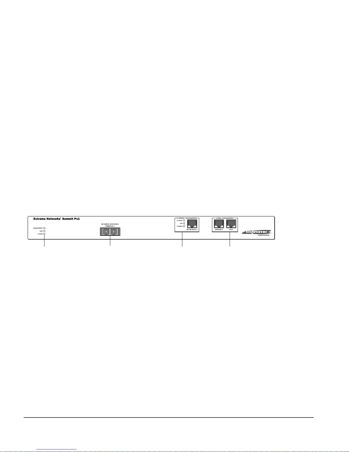
Over view of the SummitPx1 Application Switch
Summ itPx1 Front View
Figure 2-1 shows the Px seri es application switch fron t view.
Unit status
LEDs
Figure 2-1: SummitPx1 application switch front view
Px Series Ap plication Switc h Installa tion and Co nfiguration Gui de 2-1
Network Interface
port
Ethernet
Management
LEDs and port
Serial
Management
ports
SPx1_front

Table 2-1 describes the LED behavior on the SummitPx1.
Table 2-1: Px series application switch LEDs
LED Color Indicates
Link Green
The 1000Base-T link is operational.
Yellow flashing
Management Green flashing
■ Slow
■ Fast
Red
Power Green
Red
There is activity on this link.
The Px series application switch is operating normally.
Power On Self Test (POST) in progress.
The Px series application switch has failed its POST.
The Px series application switch is powered up.
The Px series application switch is indicating a power or
temperature problem.
The front panel of the SummitPx1 has four ports:
• Giga bit In ter face C onn ector (GBI C)
The Network Interface port is a Gigabit Interface Connector (GBIC) used to connect
the application switch to your loc al network.
• 100BASE-Tx Ethernet Management (RJ-45)
The Ethernet Management port (RJ-45 connector) is a 10/100 Mbps Ethernet
connection used f or out-of-band ma nagement.
• Console (serial RJ-45)
The console po rt (serial RJ- 45 connector) is used to connec t a terminal fo r local
out-of-band management. The console operates at 9600 baud, 8 data bits, no parity,
one stop bit (8-N-1) with no hardware flow control.
Use the included DB-9 adapter to connect the console to a PC serial port, using a
straight (1-8, 1-8) cable, such as a standard category 3 or category 5 Ethernet cable.
The pinouts for the DB-9 adapter are shown in Table 2-2 on page 2-3.
If you are wiring the console port to a console server, you must use a null modem
cable (1-8, 8-1).
• AUX (serial RJ -45)
The AUX port (RJ-45 connector) has the same pin-outs as the console port. The AUX
port is used for remote out-of-band management.
2-2 Px Series Applicati on Switch Ins tallation a nd Configurati on Guide
Overview of the SummitPx1 Application Switch
Table 2-2: DB-9 Adapter Pinouts
FROM: RJ45
TO: DB-9
Pin 6 Pin 1 DSR
Pin 8 Pin 2 CTS
Pin 2 Pin 3 RD
Pin 5 Pin 4 SG
NC Pin 5 -Pin 3 Pin 6 TD
Pin 7 Pin 7 RTS
Pin 4 Pin 8 DTR
SHELL
Signal Description
For more information on connecting and configuring these ports, see “Setting Up
Console Communication” on page2-6.
SummitPx1 Application Sw itch Rear View
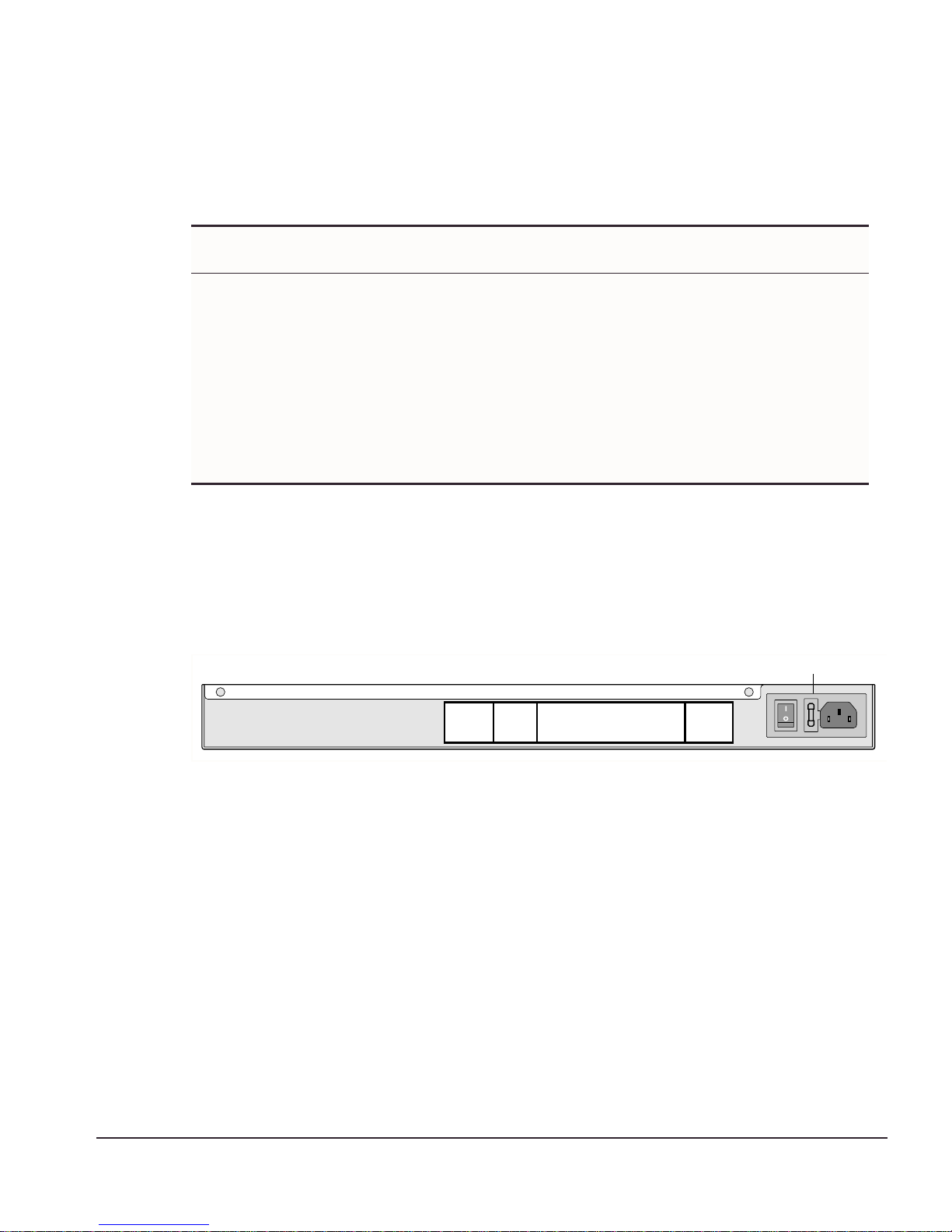
Figure 2-2 shows the Summ itPx1 application switch rear view.
Power socket and fuse
Figure 2-2: SummitPx1 application switch rear view
• Power Socket
The SummitPx1 automatically adjusts to the supply voltage. The power supply
operates down to 90 VAC. The fuse is suitable for b oth 110 VAC and 220-240 VAC
operation.
• Serial Number
Use the serial number for fault-repor ting purposes.
• MAC A ddress
A label shows the unique Ethernet MAC addresses assigned to this device.
WS_010
Px Series Ap plication Switc h Installa tion and Co nfiguration Gui de 2-3

Determining the Location
The SummitPx1 is suited for use in the office, where it can be free-s tanding or mounted
in a standard 19-inch equipment rack. Alternatively, the device can be rack-mounted in
a wiring closet or equipment room. Two mounting brackets are supplied with the
device.
When deciding where to install the SummitPx1, ensure that:
• The unit is ac cessible an d cables ca n be connected easily.
• Water or mois ture c anno t ente r the c ase o f th e unit .
• Air-flow around the unit and through the vents in the side of the case is not
restricted. You should provide a minimum of 25mm (1-inch) clearance.
• No objects are placed on top of the unit.
• Units are not stacked more than four high if the switch is free-standing.
Installing the SummitPx1 Application Switch
The application switch can be mounted in a rack or placed free-standing on a tabletop.
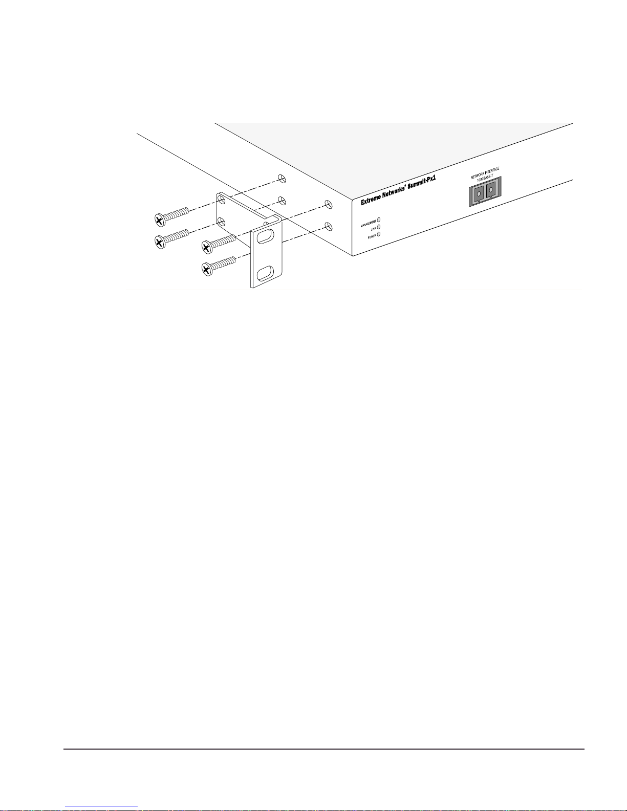
Rack Moun ting
Caution: The rack mo unt kits must not be used to suspen d the switch from
under a table or desk, or to attach to a wall.
To rack mount the application switch, follow these steps:
1 Place the device the right way up on a hard, flat surface, with the fro nt facing you.
2 Remove the existing screws from the sides of the chassis and retain for step 4.
3 Locate a mounting brack et over the mounting holes on one side of the unit.
4 Insert the screws an d fully tighten w ith a suitable s crewdriver, as shown in
Figure 2-3.
2-4 Px Series Applicati on Switch Ins tallation a nd Configurati on Guide
Powering On the SummitPx1
WS_011
Figure 2-3: Fitting the mounting bracket
5 Repeat steps 2-4 for the other side of the device.
6 Insert the application switch into the 19-inch rack. Ensure that ventilation holes are
not obstructed.
7 Secure the device with suitable screws (not provided).
8 Connec t cable s.
Free-Standing
The Summ itPx1 applic ation switch is supplied w ith four se lf-adhesive r ubber pads.
Apply the pads to the underside of the device by sticking a pad at each corner of the
device.
Up to four SummitPx1 application switches can be placed on top of one another.
Powering On the SummitPx1
To turn on power to the SummitPx1 application switch, connect the AC power cable to
the sw itch a nd th en to the w all o utlet .
After turning on power to the SummitPx1, the device performs a Power On Self-Test
(POST). During the POST, all ports are temporarily disabled, the packet LED is off, the
power LED is on, and the MGMT LED flashes. The MGMT LED flashes until the
application switch has successful ly passed the POST.
Px Series Ap plication Switc h Installa tion and Co nfiguration Gui de 2-5
If the application switch pa sses the POST, the MGMT LED blinks at a slow rate (1 blink
per second). If t he application sw itch fails the PO ST, the MGMT LED shows a solid
yellow light.
Setti ng Up Console Communi cation
To ma nage the applicat ion switch locally, you must conn ect to the managem ent console
to configure the switch’s Ethernet management port using a serial connection. This
section descr ibes how to to conf igure the SummitPx 1 for commun ication with the
console interface.
There are fo ur ports on the application switch:
• GBIC 1000bT network interface port
• 10/100BT Etherne t management po rt
• Serial console and modem management ports
Unit status
LEDs
Network Interface
port
Ethernet
Management
LEDs and port
Serial
Management
ports
SPx1_front
Any worksta tion with a Telnet facility can communi cate with the a pplication switc h
over a TCP/IP network. Telnet is enabled by default. Use Telnet to connect to either the
10/100 Mbps Ethernet management port, or to the Gigabit Ethernet network interface
port, after configuring their IP addres ses via the serial port.
The 10/100BT Ethern et management port allows the CPU to upload and download
images on a network that is seperate fro m the data network. This allows the data
network to be outside a firewa ll while the m anagement po rt is inside the firewall.
You use the serial management ports for your initial communication with the device, in
order to configure th e management and network interface ports. The serial ports use a
RJ45 connector. The Sum mitPx1 is su pplied with an RJ45-to-DB9 converter and ethernet
2-6 Px Series Applicati on Switch Ins tallation a nd Configurati on Guide

Setting Up Cons ole Commun ication
cable with which to connect most PCs to this port. The console port settings are as
follows:
Baud rate 9600
Data b its 8
Stop bit 1
Parity None
Flow control None
Each interface has a unique IP address. Before you can start a Telnet session, you must
set up the IP para meters of the port you will us e for manag ement, as descr ibed in the
following sections. To open the Telnet session, you specify the IP address of the port.
For informatio n on how to do t his, refer to the docu mentation for yo ur Telnet facility.
After the connection is established, you will see the command-line interface pro mpt and
can begin configuring the device.
Configuring S witch IP Parameters
To manage the application switch by way of a Telnet connection to the Gigabit Ethernet
port, you must first configure the switch IP parameters. To manually configure the IP
settings, follow these steps:
1 Connect a terminal or workstation running terminal-emulation software to the serial
management (console) port. See “Setting Up Console Communication” on page 2-6.
2 Configure the system IP address and default gateway. The following example sets
the address for the Gigabit Ethern et interface:
SummitPx1:4 # config system-ip 64.1.1.10 / 24 vlan 123
SummitPx1:5 # config default-gateway 64.1.1.1
The vlan argument is optional for the SummitPx1, but required for the PxM. See
“Managing the PxM” on page 4-7, and “Configuring VLANs” on page 4-8.
3 Enable the Gigabit port, commit changes, and save your configuration changes to
flash memory, so that they are in effec t after the next reboot .
SummitPx1:8 # enable port gigabit
SummitPx1:11 # build
SummitPx1:17 # save
Do you want to save to the primary configuration database (Y/N) ? y
Erasing Flash *
Px Series Ap plication Switc h Installa tion and Co nfiguration Gui de 2-7

Writing data to Flash
Done
4 When you are fin ished using the fa cility, log out of the applicatio n switch.
You can now access the Gigabit Ethernet port directly via Telnet.
Configuring the 10/100 Ethernet Management Port
The 10/100BT Ethern et management port provides dedicated remote access to the
application swit ch using TCP/IP. It supports Telnet using the command-li ne interface.
The 10/100BT port is designed to be u sed as an out-of-band managemen t port on ly. It does
not function as a load balancing port.
To use the management interface, you must assign it an IP address and subnetwork
mask, using the following comma nd:
config mgmt ip <ipaddress> / <netmask bit length>
The 10/100BT port has a separate routing table. By default, no routes are installed in the
routing table. You must explicitly configure routes. After the IP address has been
configured, install a route for the network, usi ng the following command:
config mgmt iproute dest-ip <ipaddress> gateway <ipaddress>
You can add additional routes, as needed.
The configuration of management port i nformation is executed immediately. You
do not need t o use the
build command.
The following example configures an IP address and installs two network routes:
station1:4 # config mgmt ipaddress 10.10.10.2 / 24
station1:5 # config mgmt iproute dest-ip 10.10.10.0 gateway 10.10.10.1
station1:6 # config mgmt iproute dest-ip 10.10.11.0 gateway 10.10.10.1
2-8 Px Series Applicati on Switch Ins tallation a nd Configurati on Guide

3
Installing the PxM Application
Switch Module
The PxM co nfiguration of th e Px series app lication switc h is a BlackDiam ond module .
The configur ation informat ion and spec ifications for the B lackDiamond I/O module s
are described in d etail in the E xtreme Netwo rks Consolidated Hardware Guide, as w ell as
the module ins tallation and rem oval procedures. For convenience, t he information on
installing and removing modules is repeated here.
To ma nage the applicat ion switch lo cally, you mu st connect a m anagement con sole to
the switch’s Et hernet managem ent port using a serial c onnection. Do thi s in the same
way as for the SummitPx1; see “Settin g Up Console Communication” on page 2-6.
This chapter cont ains the follow ing sections:
• Installing I/O Mo dules on page 3-1
• Removing I/O Modules on page 3-2
Installing I/O Modules
You can insert I/O modules at any time, without causing disruption of network
services.
To in stall an I/O mod ule:
1 Select a slot for the modu le:
• Slots numbered 1 through 16 in the BlackDiamond 6816
• Slots numbered 1 through 8 in the BlackDiamond 6808
Px Series Ap plication Switc h Installa tion and Co nfiguration Gui de 3-1

Caution: You can install I/O modules only in slots 1 through 16 in the
BlackDiamond 6816 or s lots 1 through 8 in the BlackDiamond 680 8. I/O m odules
do not fit in slots A, B, C, or D. Forceful insertion can da mage the I/O module.
2 Attach the ESD strap that is provided to your wrist and connect the metal end to the
ground receptacle that is located on the top-left corner of the switch front panel.
3 For the BlackDiamond 6816, ensure that the module is horizontal with the module
name to the left and that the ejector/injector handles are extended.
For the BlackDiamond 6808, ensure that the module is vertical with the module
name at the top and that the ejector/injector handles are ext ended.
4 Slide the module into the appro priate slot of the chassis (slots 1 through 16 in the
BlackDiamond 6816 or slots 1 through 8 in the BlackDiamond 6808), until it makes
contact with the backplane.
As the module begins to seat in the chassis, the ejector/injector handles begin to
close.
5 To close the ejector/injector handles, use both hands simultaneously to push the
handles toward the center of the module.
6 To secure t he module, tigh ten the two screws using a #1 Phillips s crewdriver.
Note: Tighten the screws before inserting additional modules. Otherw ise, you
might unseat modules that you have not secured.
7 Repeat this procedure for additional modules, if applicable.
8 Leave the ESD strap permanently connected to the chassis, so that it is always
available when you need to handle ESD-sensitive components.
Removing I/O Modules
All BlackDiamond 6800 series modules (MSM64i and I/O modules) are hot-swappable.
You do not need to power off the system to remove a module.
To remove an I/O module:
1 Attach the ESD strap that is provided to your wrist and connect the metal end to the
ground receptacle that is located on the top-left corner of the switch front panel.
2 Use a #1 Phillips screwdriver to uns crew the two captiv e screws.
3-2 Px Series Applicati on Switch Ins tallation a nd Configurati on Guide

Removing I/O Modu les
3 Simultaneously rotate the ejector/injector handles outward to disengage the module
from the backplane.
4 Slide the module out of the chassis.
5 If you are not going to install a replacement I/O module, cover the slot with a blank
faceplate. Otherwise, follow the I/O module installation procedure above.
6 Repeat this procedure for additional modules, if applicable.
7 Leave the ESD strap permanently connected to the chassis, so that it is always
available when you need to handle ESD-sensitive components.
Px Series Ap plication Switc h Installa tion and Co nfiguration Gui de 3-3

3-4 Px Series Applicati on Switch Ins tallation a nd Configurati on Guide
 Loading...