

Page 1

Px Series
Application Switch
Installation and
Configuration Guide
Extr eme N etwo rk s, In c.
3585 Monroe Street
Santa Clara, California 95051
(888) 257-3000
http://www.extremenetworks.com
Part number : 100101-00 Rev. 02
Published: April 200 2
Page 2

©2002 E xtrem e Ne tw orks , In c. A ll ri ghts rese rve d. E xt reme Ne two rk s an d Blac kDi am ond are
registered trademarks of Extreme Networks, Inc. in the United States and certain other jurisdictions.
Extreme Ware, Extrem eWare Vista, Extre meWorks, E xt remeA ssi st, E xtrem eA ssi st1, Ext reme Assis t2 ,
PartnerAss ist, Ex treme S tandb y Router Protoc ol, ESR P, SmartTraps, Alpine, Summit , Sum mit1,
Summit4, Summit4/FX, Summit7i, Summit24, Summit48, Summit Virtual Chassis, SummitLink,
Summi tGbX , Su mmi tPx1 , Su mmi tRPS and the Ext reme N e twor ks l ogo are tr ade mar ks o f Ex trem e
Netwo rks, I nc ., wh ich m ay be re giste red o r pe ndin g regi st rati on in cer ta in ju risd ict ions . T he Ext reme
Turbodrive l ogo is a s erv ice m ark of E xtrem e Ne two rks , whi ch m ay b e re giste red o r pe ndin g
registration in certain jurisdictions. Specifications are subject to change without notice.
NetWare and Novell are registered trademarks of Novell, Inc. Merit is a registered trademark of Merit
Netwo rk, In c. Sola ris i s a tra dema rk of Su n Mi crosys tem s, Inc. F5, BIG /ip, and 3DN S are regi ste red
tradem ark s of F 5 Ne tw ork s, In c. s ee /IT is a trad emar k o f F5 N etwo rk s, I nc.
All other registered trademarks, trademarks and service marks are property of their respective owners.
II
Page 3

Contents
Preface
Introduction 1-vii
Conventions 1-viii
Related Publications 1-ix
1 Server Load Balancing Concepts
Purpose of Server Load Balancing 1-1
Terms 1-2
Load Balancing Modes 1-3
Laye r 4 L oad Bala nci ng 1-3
Layer 7 Load Balancing a nd Content Analys is 1-4
Port Rewrite 1-6
Getting Started on Load Balancing Configuration 1-6
2 Installing the SummitPx1 Application Switch
Overview of the SummitPx1 Application Switch 2-1
SummitPx1 Front View 2-1
SummitPx1 Ap plication Switch R ear View 2-3
Determining the Location 2-4
Installing the SummitPx1 Application Switch 2-4
Rack Mounting 2-4
Px Series Appli cation Switch In stallation and Config uration Guide iii
Page 4

Free-Standing 2-5
Powering On the Su mmit Px1 2-5
Setting Up Console Communication 2-6
Configuring Swit ch IP Parameters 2-7
Configuring the 10/100 Ethernet Management Port 2-8
3 Installing the PxM Application Switch Module
Installing I/O Modules 3-1
Removing I /O Mo dules 3-2
4 Managing the Switch
Using the Command-Line Interface 4-2
Abbreviated S yntax and C ommand C ompletio n 4-2
Syntax Symbols 4-2
Line-Editing Ke ys 4-3
Specifying Text Values 4-3
Command History 4-4
Prompt Text 4-4
Configuri ng Man agemen t Access 4-4
Changing the Default Passwords 4-5
Creating Ac counts 4-6
Managing the PxM 4-7
Configuring VLANs 4-8
Configurin g SNM P 4-9
Configuri ng DNS Client Se rvices 4-10
Using Secure Shell 2 (SSH2) 4-11
Enabling SSH2 for Inbound Switch Access 4-12
Using SCP2 from an External SSH2 Client 4-13
SSH2 Client Functions on the Switch 4-14
Utilities 4-15
Showing CPU Load 4-15
Checking Basic Connectivity 4-15
Logging 4-16
iv Px Series Applicati on Switch Ins tallation a nd Configurati on Guide
Page 5

Configuring a Startup Banner Message 4-17
Starting the GlobalPx Content Director Agent 4-17
Example Configuration 4-18
5 Configuring Servers and Services
Configuring Real Servers 5-1
Configurin g Server G roups 5-2
Configurin g Virtual Service s 5-3
Layer 4 Port-based Load Balancing 5-4
Layer 7 Virtual Services 5-4
Configuring Traffic Tagging 5-5
Configura tion Exa mple 5-6
6 Choosing Policies, Persistence Modes, and NAT
Scheduling Policies 6-1
Persistence Modes 6-2
UDP Flow Persistenc e 6-3
Client IP Persistenc e Mode 6-3
Cookie Persist ence Modes 6-5
SSL Session Identifier Persistence 6-13
NAT Mode s 6-14
Full-NAT Mode 6-14
Server-only Half-NAT Mode 6-15
Configura tion Exa mple 6-17
7 URL Switching
Domain and URL Switching 7-1
Domain Switching 7-2
URL Switchi ng 7-4
Configuring URL Switching 7-4
Creating Domain and URL Switching Rules 7-8
Modifying Exis ting URL Rul es and Domains 7-9
Px Series Appli cation Switch In stallation and Config uration Guide v
Page 6

Configura tion Exa mple 7-9
8 Configuring Redundancy
Using VRRP with the SummitPx1 8-1
Adding and C onfigurin g VRRPs 8-2
Using VRRP in Existing Redu ndant Netwo rks 8-3
VRRP Automatic Synchronization 8-4
Configurin g Redu ndancy f or the PxM 8-6
Using ESRP with the Px M 8-6
Configuring the Px M for Multiple VLANs 8 -7
Configuring a Default Gateway 8-8
9 Health Checks
Overview 9-1
Server Startup Pacing 9-2
Health Checking Procedure 9-3
Configuring Health Checks 9-4
Types of Health Checks 9-4
Timers and Co unters 9-4
10 Monitoring the Switch
Showing Traffic Statistics 10-1
Showing Configuration Details 10-3
Configuration Displays 10-4
Status Displays 10-5
Managing and Troubleshooting Operation 10-7
Index
Index of Commands
vi Px Series Applicati on Switch Ins tallation a nd Configur ation Guid e
Page 7

Preface
This preface provides an overview of this guide, describes guide conventions, and lists
other publications that may be us eful.
Introduction
This guide provides the required information to configure the Extreme Networks Px
series application switches, Su mmitPx1
This guide is intended for use by network administrators who are responsible for
installing and setting up network equipment. It assumes a basic working knowledge of:
• Local area netw orks (LAN s)
• Ethernet concepts
• Ethernet sw itching and br idging conce pts
• Routing concepts
• Internet Protocol (IP) conce pts, including conne ction initiation pro cess
• Netw ork A ddres s Translat ion ( NAT)
If the information in the release notes shi pped with your switch differs from the
information in this guide, follow the release notes.
Px Series Appli cation Switch In stallation and Config uration Guide vii
TM
and P xMTM.
Page 8

Preface
Conventions
Ta ble 1 and Table 2 list conven tions that are used th roughout this guid e.
Table 1: Notice Icons
Icon Notice Type Alerts you to...
Note Important features or instructions.
Caution Risk of personal injury, system damage, or loss of data.
Warning Risk of severe personal injury.
Table 2: Text Conventions
Convention Description
Screen displays This typeface indicates command syntax, or represents information
as it appears on the screen.
The words “enter”
and “type”
[Key] names Key names are written with brackets, such as [Return] or [Esc].
Words in italicized type Italics emphasize a point or denote new terms at the place where
When you see the word “enter” in this guide, you must type
something, and then press the Return or Enter key. Do not press
the Return or Enter key when an instruction simply says “type.”
If you must press two or more keys simultaneously, the key names
are linked with a plus sign (+). Example:
Press [Ctr l]+[Alt]+ [Del].
they are defined in the text.
viii Px Series Applicati on Switch Ins tallation a nd Configurati on Guide
Page 9

Related Publications
Relat ed Publicati ons
The publicat ions related to th is one are:
• ExtremeWare Software User G uide
• Px Series Application Switch Release N otes
Documentation for Extreme products is available on the World Wide Web at the
following loca tion:
• http://www.extremenetworks.com
Px Series Appli cation Switch In stallation and Config uration Guide ix
Page 10

Preface
x Px Seri es Applicati on Switch Ins tallation a nd Configurati on Guide
Page 11

1
Server Load Balancing Concepts
The Px series application switch marks the next step in server load balancing. Using a
revolutionary hardware design, t he Px series app lication switch is d esigned to help
website adminis trators achie ve levels of av ailability and s calability neve r before
possible.
This chapter cont ains the following s ections:
• Purpose of Server Load Balancing on page 1-1
• Load Balancin g Modes on pa ge 1-3
• Port Rewrite on page 1-6
• Getting Started o n Load Balancin g Configuration on page 1-6
Purpose of Server Load Balancing
An application switch in creases website availabili ty by allowing for web serv ers to fail
(or be shut down for maintenance) without a website outage. It also improves the
response times of the website and increases the traffic-handling capacity of the website
by allowing mult iple servers to b e used together as a single site.
Px Series Appli cation Switch In stallation and Config uration Guide 1-1
Page 12
The Px series application switch can examine actual user requests, rather than simply
forwarding the requests to the servers. You can use the powerful array of tools provided
by the Px series app lication switch to scale websit es by:
• Creating special purpose servers
• Making better use of web caches
• Allowing movem ent of web conten t without extensiv e re-linking of the site
Terms
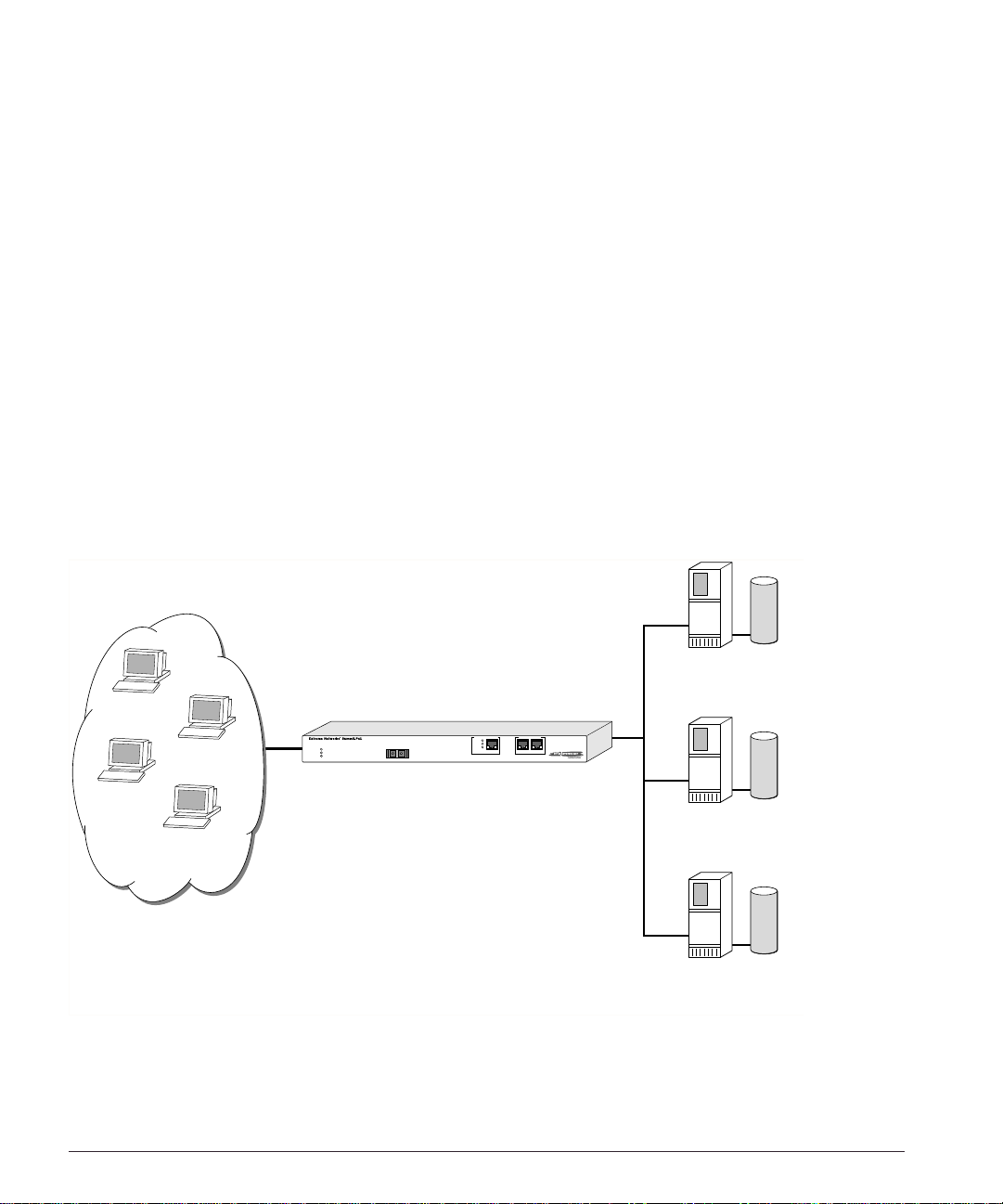
The Px series application switch creates a level of abstraction between the real servers
and the Internet, by configuring a virtual IP (VIP) address and port on the application
switch. The VIP has a globally-reachable public IP address, and corresponds to the DNS
entry for the we bsite. All traffic for the website is sent to the applicatio n switch, whic h
applies policies to decide how to forward the traffic to a real server.
Figure 1-1 s hows several Inter net users all conne cting to the webs ite www.busy.com.
Real Server 1
10.1.1.3
101.1.35.2
193.16.1.36
Virtual Server
www.busy.com
235.19.10.1
64.10.10.100
Real Server 2
64.64.6.4
10.1.1.4
Internet clients
Real Server 3
10.1.1.5
WS_012
Figure 1-1: Conceptual view of server load balancing
1-2 Px Series Application Switch Ins tallation a nd Configurati on Guide
Page 13

Load Balancing Modes
In this document, the Internet users are referred to as clients, because they are clients of
the application switch. The website, whic h is actually a n address inside t he applicatio n
switch, is also c alled a virtual IP a ddress, or VIP. Because the Px series application switch
uses the unique combination of IP address and source port, the VIP is referred to as a
virtual service.
Load Balancing Modes
The Px series a pplication swi tch can perform packet redirection for load balancing in
two different ways:
• Layer 4 load balancing
• Layer 7 load balancing
Layer 4 Lo ad Balancin g
In layer 4 mode, the application switch decide s which server s hould receive a give n
user request using server selection poli cies. It selects a server without looking at the
content of the request. The following server selection policies are supported by the Px
series applicat ion switch:
• Round robin
• Weight ed round ro bin
• Least con nections
• Weighted least con nections
For more information on policies, see Chapter 6.
The applic ation sw itch c an bala nce alm ost any traffic us ing ne twork address transla tion
(NAT) at layer 4. The applicatio n switch rewrites t he destination IP a ddress of the
request to point to the real server selected to handle the request, and sets the source IP
address of the request to point to one of the internal IP addresses of the Px series
application switch. When the server responds to the request, the application switch
rewrites the response so that it appears to originate from its VIP address, and forwards
the response to the client.
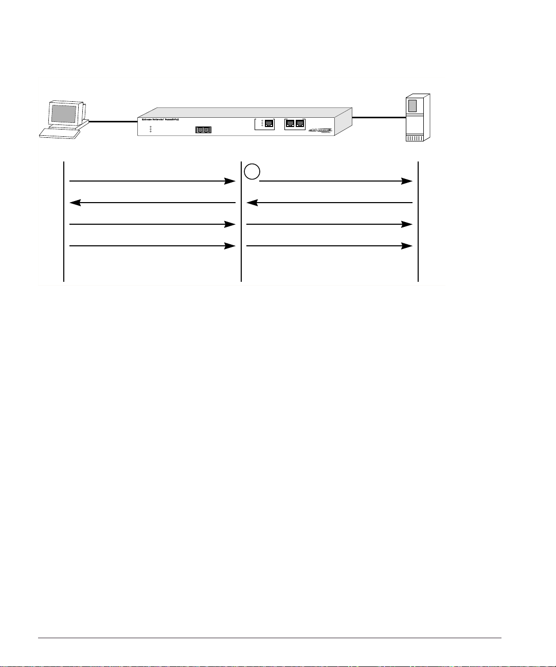
Figure 1-2 illus trates a single c lient-server tr ansaction using layer 4.
Px Series Appli cation Switch In stallation and Config uration Guide 1-3
Page 14
Client Real Server
SYN
1
SYN/ACK
ACK
DATA
(http request)
WS_013
Figure 1-2: Single client-server transaction using layer 4
As soon as the fir st request from the client is received at the application s witch, the
application switch uses the server-selection policy configured for the VIP to select the
server and immediately sends out the NAT-ed request to the real server. The client and
server continue the connection establishment protocol using the application switch in
the middle, NAT-ing the traffic. After the connection is established, an HTTP request is
sent and the server responds.
Layer 7 Load Balancing and Content Analysis
To make server-selection decisions based on cookies or the URL being requested by the
client, the appli cation swit ch must actu ally look ins ide the client reques t. Becaus e this
data request is only sent out after a connection is established, the Px series application
switch must first act as a proxy for the server by acting as the endpoint of the TCP/IP
connection from the c lient. This process is called layer 7 load balancing.
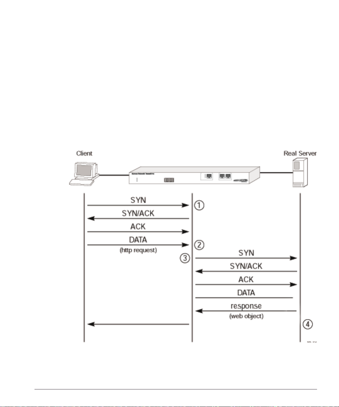
The Px series application switch delays the establishment of a connection to a server
until the first 1500 bytes of actual data (the HTTP request) is received from the client.
The application switch then takes the content being requested, along with the domain to
which the request pertains, and applies policy rules. Based on the outcome of the policy
decision, the a pplication switch establishes a T CP connection w ith the real server
1-4 Px Series Application Switch Ins tallation a nd Configurati on Guide
Page 15
Load Balancing Modes
chosen to process the request, using a source IP address that is part of a proxy pool
inside the app lication switc h.
After a connection is established between the application switch and the real server, the
application switch forwards the buffered data to the server. The server sends any
response to the ap plication switch . The applicatio n switch tr anslates th e IP source
address and port numbers appropriately, along with the TCP sequence and
acknowledgment numbers, and then forwards the data to the real client on the Internet.
Return traffic from the real server does not require content analysis, and is simply
rewritten by the NAT engine.
Figure 3 illustrates the sequence used to establish a layer 7 requ est.
Figure 1-3: Establishing a layer 7 request
Px Series Appli cation Switch In stallation and Config uration Guide 1-5
Page 16

Port Rewrite
When a request is sent by a client to a VIP service, the request contains the well-known
port number for the requested application. For example, the well-known port number
for HTTP is port 80.
You can configure the application switch to rewrite the port, configuring a server group
to use a specific port, other than the well-known port number for the application. Port
rewrite is useful in ins tances where m ultiple domain s are configured on t he same s erver
(or all servers in the same server group) and each domain has its own server process.
By giving each domain its own port number, each server process can be configured to
listen f or requ ests a t its o wn po rt.
Getting Started on Load Balancing Configuration
To successfully configure the Px series ap plication switc h to perform lo ad balancing
operations, you must consider the following:
• Do you want to use full NAT or server-only NAT mode? For more information on
NAT, see Chapter 6.
• Do you want to use IP address history? For more information on IP address history,
see Chapter 6.
• What server se lection policies d o you want to use ? For more informati on on
selection policies, see Chapter 6.
• If URL switchin g is going to be im plemente d, what DNS domains an d patterns will
be used? For m ore information on URL sw itching, see Cha pter 7.
• If cookies will be used, what cookie mode will be selected, and are the cookies
configured properly on the web servers? For more information on cookies, see
Chapter 6.
After these decisions have been made, follow these steps to configure load balancing:
1 Configure the syste m IP and related inf ormation. Fo r more informatio n, see
Chapter 4.
2 Configure the appropriate global parameters such as NAT mode, proxy-IPs, and
stickiness options. For more information, see Chapter 6.
3 Configure the servers and virtual services:
1-6 Px Series Application Switch Ins tallation a nd Configurati on Guide
Page 17

Getting Star ted on Loa d Balancin g Configuratio n
a Configure the real ser vers that will be load balan ced.
b Create groups of servers, and put the real servers into them.
c Create a virtual service.
— If the virtual service is layer 4, assign a se rver group to it.
— If the virtual service is layer 7, create the appropriate domains and pattern-rules,
and assign server groups to the pattern-rules.
For more information, s ee Chapter 5.
Px Series Appli cation Switch In stallation and Config uration Guide 1-7
Page 18

1-8 Px Series Application Switch Ins tallation a nd Configurati on Guide
Page 19

2
Installing the SummitPx1 Application Switch
This chapter de scribes how t o install the Su mmitPx1 conf iguration of t he Px series
application switch . It contains the fo llowing sectio ns:
• Overview of the SummitPx1 Application Switch on page 2-1
• Determining the Lo cation on page 2-4
• Installing the Summ itPx1 Applic ation Switch on pa ge 2-4
• Setting Up Cons ole Commu nication on pa ge 2-6
• Powering On the SummitPx1 on page 2-5
Over view of the SummitPx1 Application Switch
Summ itPx1 Front View
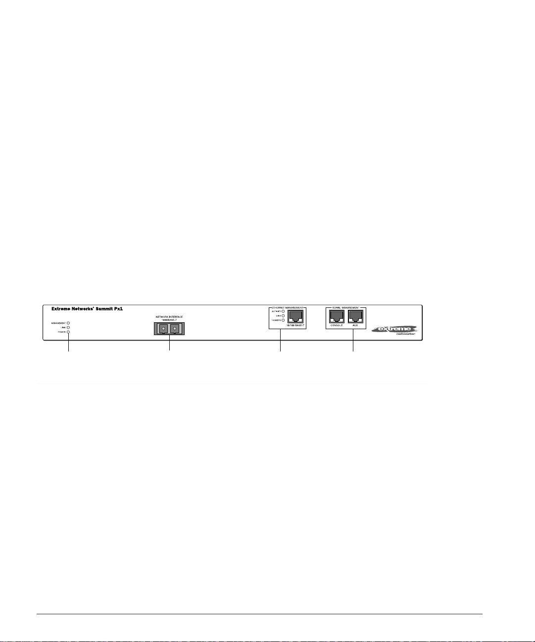
Figure2-1 shows the Px series application switch front view.
Unit status
LEDs
Figure 2-1: SummitPx1 application switch front view
Px Series Appli cation Switch In stallation and Config uration Guide 2-1
Network Interface
port
Ethernet
Management
LEDs and port
Serial
Management
ports
SPx1_front
Page 20

Table 2-1 describes the LED behavior on the SummitPx1.
Table 2-1: Px series application switch LEDs
LED Color Indicates
Link Green
Yellow flashing
Management Green flashing
■ Slow
■ Fast
Red
Power Green
Red
The 1000Base-T link is operational.
There is activity on this link.
The Px series application switch is operating normally.
Power On Self Test (POST) in progress.
The Px series application switch has failed its POST.
The Px series application switch is powered up.
The Px series application switch is indicating a power or
temperature problem.
The front panel of the SummitPx1 has four ports:
• Giga bit In terfa ce Co nnec tor (GBI C)
The Network Interface port is a Gigabit Interface Connector (GBIC) used to connect
the application sw itch to your loc al network.
• 100BASE-Tx Ethernet Management (RJ-45)
The Ethernet Management port (RJ-45 connector) is a 10/100 Mbps Ethernet
connection used for o ut-of-band mana gement.
• Console (serial RJ-45)
The console por t (serial RJ-4 5 connector) is us ed to connec t a terminal for lo cal
out-of-band management. The console operates at 9600 baud, 8 data bits, no parity,
one stop bit (8-N-1) with no hardware flow control.
Use the included DB-9 adapter to connect the console to a PC serial port, using a
straight (1-8, 1-8) cable, such as a standard category 3 or category 5 Ethernet cable.
The pinouts for the DB-9 adapter are shown in Table 2-2 on page 2-3.
If you are wiring the console port to a console server, you must use a null modem
cable (1-8, 8-1).
• AUX (serial RJ- 45)
The AUX port (RJ-45 connector) has the same pi n-outs as the console port. The AUX
port is used for remote out-of-band management.
2-2 Px Series Application Switch Ins tallation a nd Configurati on Guide
Page 21

Overview of the SummitPx1 Application Switch
Table 2-2: DB-9 Adapter Pinouts
FROM: RJ45
TO: DB-9
Pin 6 Pin 1 DSR
Pin 8 Pin 2 CTS
Pin 2 Pin 3 RD
Pin 5 Pin 4 SG
NC Pi n 5 -Pin 3 Pin 6 TD
Pin 7 Pin 7 RTS
Pin 4 Pin 8 DTR
SHELL
Signal Description
For more information on connecting and configuring these ports, see “Setting Up
Console Communication” on page 2-6.
SummitPx1 Application Sw itch Rear V iew
Figure 2-2 shows the SummitPx1 application switch rear view.
Power socket and fuse
Figure 2-2: SummitPx1 application switch rear view
• Power Socket
The SummitPx1 automatically adjusts to the supply voltage. The power supply
operates down to 90 VAC. The fuse is suitable for both 110 VAC and 220-240 VAC
operation.
• Serial Number
Use the serial number for fault-reporting purposes.
• MAC Addre ss
A label shows the unique Ethernet MAC addresses assigned to this device.
WS_010
Px Series Appli cation Switch In stallation and Config uration Guide 2-3
Page 22

Determining the Location
The SummitPx1 is suited for use in the office, where it can be free-standing or mounted
in a standard 19-inch equipment rack. Alternatively, the device can be rack-mounted in
a wiring closet or equipment room. Two mounting brackets are supplied with the
device.
When deciding where to install the SummitPx1, ensure that:
• The unit is ac cessible and c ables can be connected e asily.
• Water o r moi sture c anno t en ter the case of th e uni t.
• Air-flow around the unit and through the vents in the side of the case is not
restricted. You should provide a minimum of 25mm (1-inch) clearance.
• No objects are placed on top of the unit.
• Units are not stacked more than four high if the switch is free-standing.
Installing the SummitPx1 Application Switch
The application switch can be mounted in a rack or placed free-standing on a tabletop.
Rack Mountin g
Caution: The rack mount kits must not be u sed to suspen d the switch from
under a table or desk, or to attach to a wall.
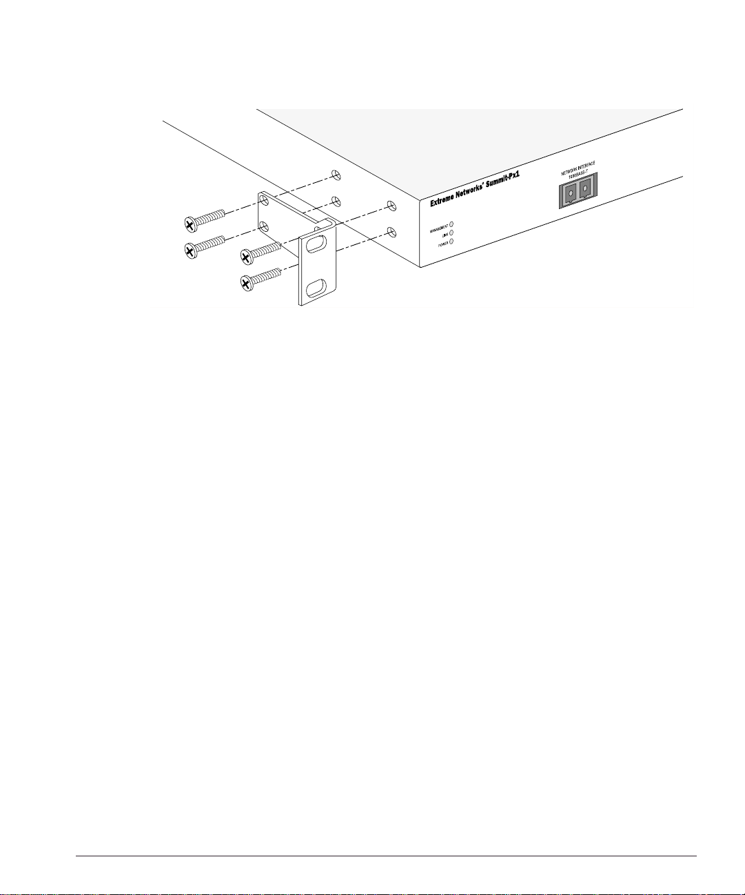
To rack mo unt the application switch, follow these steps:
1 Place the device the right way up on a hard, flat surface, with the front facing you.
2 Remove the existing screws from the sides of the chassis and retain for step 4.
3 Locate a mounting bracket over the mounting holes on one side of the unit.
4 Insert the screws and f ully tighten wit h a suitable screw driver, as shown in
Figure 2-3.
2-4 Px Series Application Switch Ins tallation a nd Configurati on Guide
Page 23
Powering On the SummitPx1
WS_011
Figure 2-3: Fitting the mounting bracket
5 Repeat steps 2-4 for the other side of the device.
6 Insert the application switch into the 19-inch rack. Ensure that ventilation holes are
not obstructed.
7 Secure the device with suitable screws (not provided).
8 Connect cables .
Free-Standing
The Summit Px1 applic ation switch is supplied w ith four self -adhesive r ubber pads.
Apply the pads to the underside of the device by sticking a pad at each corner of the
device.
Up to four SummitPx1 application switches can be placed on top of one another.
Powering On the SummitPx1
To turn on power to the SummitPx1 application switch, connect the AC power cable to
the sw itch a nd th en to the w all o utlet .
After turning on power to the SummitPx1, the device performs a Power On Self-Test
(POST). During the POST, all ports are temporarily disabled, the packet LED is off, the
power LED is on, and the MGMT LED flashes. The MGMT LED flashes until the
application switch has successfully passed the POST.
Px Series Appli cation Switch In stallation and Config uration Guide 2-5
Page 24
If the application switch pas ses the POST, the MGMT LED blinks at a slow rate (1 blink
per second). If the application swit ch fails the POS T, the MGMT LED shows a solid
yellow light.
Setti ng Up Conso le Communica tion
To manage the app lication switch locally, you must conn ect to the managem ent console
to configure the switch’s Ethernet management port using a serial connection. This
section describ es how to to configu re the SummitPx 1 for commun ication with the
console interface.
There are four ports on the application switch:
• GBIC 1000bT network interface port
• 10/100BT Ethernet management po rt
• Serial console and modem management ports
Unit status
LEDs
Network Interface
port
Ethernet
Management
LEDs and port
Serial
Management
ports
SPx1_front
Any workstation w ith a Telnet facility can communi cate with the ap plication switc h
over a TCP/IP network. Telnet is enabled by default. Use Telnet to connect to either the
10/100 Mbps Ethernet management port, or to the Gigabit Ethernet network interface
port, after configuring their IP addresses via the serial port.
The 10/100BT Ethernet management port allows the CPU to upload and download
images on a network that is seperate from the data network. This allows the data
network to be o utside a firewall w hile the man agement port is inside the f irewall.
You use the serial management ports for your initial communication with the device, in
order to configure the management and network interface ports. The serial ports use a
RJ45 connector. The SummitPx1 is supplied with an RJ45-to-DB9 converter and ethernet
2-6 Px Series Application Switch Ins tallation a nd Configurati on Guide
Page 25

Setting Up Consol e Communic ation
cable with which to connect most PCs to this port. The console port settings are as
follows:
Baud rate 9600
Data bi ts 8
Stop bit 1
Parity None
Flow control None
Each interface has a unique IP address. Before you can start a Telnet session, you must
set up the IP param eters of the po rt you will us e for manageme nt, as describ ed in the
following sections. To open the Telnet session, you specify the IP address of the port.
For information o n how to do t his, refer to the docum entation for your Telnet facility.
After the connection is established, you will see the command-line interface prompt and
can begin configuring the device.
Configuring S witch IP Parameters
To m anage the application switch by way of a Telnet connection to the Gigabit Ethernet
port, you must first configure the switch IP parameters. To manually configure the IP
settings, follow these steps:
1 Connect a terminal or workstation running terminal-emulation software to the serial
management (console) port. See “Setting Up Console Communication” on page 2-6.
2 Configure the system IP address and default gateway. The following example sets
the address for the Gigabit Ethernet interface:
SummitPx1:4 # confi g system-ip 64 .1.1.10 / 24 vlan 123
SummitPx1:5 # config default-gateway 64.1.1.1
The vlan argument is optional for the SummitPx1, but required for the PxM. See
“Managing the PxM” on page 4-7, and “Configuring VLANs” on page 4-8.
3 Enable the Gigabit port, commit changes, and save your configuration changes to
flash memory, so that they are in effect after the next reboot.
SummitPx1:8 # enable port gigabit
SummitPx1:11 # build
SummitPx1:17 # save
Do you want to save to the primary configuration database (Y/N) ? y
Erasing Flash *
Px Series Appli cation Switch In stallation and Config uration Guide 2-7
Page 26

Writing data to Flash
Done
4 When you are finish ed using the facili ty, lo g out of the applic ation switch.
You can now access the Gigabit Ethernet port directly via Telnet.
Configuring the 10/100 Ethernet Management Port
The 10/100BT Ethernet management port provides dedicated remote access to the
application switch using TCP/IP. It supports Telnet using the command- line interface.
The 10/100BT port is designed to be used as an out-of-band management p ort only. It does
not function as a load balancing port.
To use the management interface, you must assign it an IP address and subnetwork
mask, using the f ollowing command :
config mgmt ip <ipa ddress> / <netm ask bit length>
The 10/100BT port has a separate routing table. By default, no routes are installed in the
routing table. You must explicitly configure routes. After the IP address has been
configured, install a route for the network, using t he following com mand:
config mgmt iproute dest-ip <ipad dress> gateway <ipaddre ss>
You can add additional routes, as needed.
The configuration of m anagement port informat ion is executed immediately. You
do not need t o use the
build com mand.
The following example configures an IP address and installs two network routes:
station1:4 # config mgmt ipaddress 10. 10.10.2 / 24
station1:5 # config mgmt iproute dest- ip 10.10.10.0 gateway 10 .10.10.1
station1:6 # config mgmt iproute dest- ip 10.10.11.0 gateway 10 .10.10.1
2-8 Px Series Application Switch Ins tallation a nd Configurati on Guide
Page 27

3
Installing the PxM Application Switch Module
The PxM conf iguration of th e Px series applic ation switch is a BlackDiam ond module.
The configuratio n informatio n and specif ications for the B lackDiamond I/O modules
are described in d etail in the E xtreme Networks Consolidated H ardware Guide, as w ell as
the module ins tallation and remo val procedures. For conv enience, the information on
installing and removing modules is repeated here.
To manage the a pplication switch locally, you must con nect a manage ment console to
the switch’s Ethern et manageme nt port using a serial co nnection. Do this in the same
way as for the SummitPx1; see “Setting Up Console Communication” on page 2-6.
This chapter cont ains the following s ections:
• Installing I/O Modu les on page 3-1
• Removing I/O Modules on page 3-2
Installing I/O Modules
You can insert I/O modules at any time, without causing disruption of network
services.
To install an I/O module:
1 Select a slot f or the modu le:
• Slots numbered 1 through 16 in the BlackDiamond 6816
• Slots numbered 1 through 8 in the BlackDiamond 6808
Px Series Appli cation Switch In stallation and Config uration Guide 3-1
Page 28

Caution: You can install I/O modules only in slots 1 through 16 in the
BlackDiamond 6816 or slots 1 through 8 in the B lackDiamond 680 8. I/O modul es
do not fit in s lots A, B, C, or D. Forceful insertion can da mage the I/O module.
2 Attach the ESD strap that is provided to your wrist and connect the metal end to the
ground receptacle that is located on the top-left corner of the switch front panel.
3 For the BlackDiamond 6816, ensure that the module is horizontal with the module
name to the left and that the ejector/injector handles are extended.
For the BlackDiamond 6808, ensure that the module is vertical with the module
name at the top and that the ejector/injector handles are extended.
4 Slide the module into the appropriate slot of the chassis (slots 1 through 16 in the
BlackDiamond 6816 or slots 1 through 8 in the BlackDiamond 6808), until it makes
contact with the backplane.
As the module begins to seat in the chassis, the ejector/injector handles begin to
close.
5 To c lose the ejector/injector handles, use both hands simultaneously to push the
handles toward the center of the module.
6 To secure the module, t ighten the two screw s using a #1 Phillip s screwdrive r.
Note: Tighten the s crews before inserting additional modules. Otherwise, you
might unseat modules that you have not secured.
7 Repeat this procedure for additional modules, if applicable.
8 Leave the ESD strap permanently connected to the chassis, so that it is always
available when you need to handle ESD-sensitive components.
Removing I/O Modules
All BlackDiamond 6800 series modules (MSM64i and I/O modules) are hot-swappable.
You do not need to power off the system to remove a module.
To remove an I/O module:
1 Attach the ESD strap that is provided to your wrist and connect the metal end to the
ground receptacle that is located on the top-left corner of the switch front panel.
2 Use a #1 Phillips s crewdriver to unscrew the two captive s crews.
3-2 Px Series Application Switch Ins tallation a nd Configurati on Guide
Page 29

Removing I/O Modules
3 Simultaneously rotate the ejector/injector handles outward to disengage the module
from the backplane.
4 Slide the module out of the chassis.
5 If you are not going to install a replacement I/O module, cover the slot with a blank
faceplate. Otherwise, follow the I/O module installation procedure above.
6 Repeat this procedure for additional modules, if applicable.
7 Leave the ESD strap permanently connected to the chassis, so that it is always
available when you need to handle ESD-sensitive components.
Px Series Appli cation Switch In stallation and Config uration Guide 3-3
Page 30

3-4 Px Series Application Switch Ins tallation a nd Configurati on Guide
Page 31

4
Managing the Switch
This chapter covers the follo wing top ics:
• Using the Command-Line Interface page 4-2
• Configuring Mana gement Access on pa ge 4-4
• Managing the PxM on page 4-7
• Configuring V LANs on page 4-8
• Configuring SNMP on page 4-9
• Configuring DNS Client Serv ices on page 4-10
• Utilities on page 4-15
• Example Configuration on page 4-18
Px Series Appli cation Switch In stallation and Config uration Guide 4-1
Page 32

Using the Command-Line Interface
To use t he command-line interface:
1 Enter the command name. You can use abbreviated syntax; see below.
2 If the command includes a parameter, enter the parameter name and value.
The value specifies how you want the parameter to be set. Values can be numbers,
strings, or addresses, depending on the parameter.
3 After entering the complete command, press [Return].
Most commands are not executed immediately, but are deferred until you issue the
build command. Exceptions are noted when the commands are described in this
manual.
Abbreviated Syntax and Command Completion
Abbreviated syntax is the shortest unambiguous abbreviation of a command or
param eter. Typica lly, this is th e first t hree l etters of th e comm and .
The Px series application switch provides command completion by way of the [Tab]
key. If you enter a command using the abbreviated syntax, pressing the [Tab] key
displays a list of available options, and places the cursor at the end of the command.
The command-line interface also has a syntax helper that provides assistance if you
have ent ered an in correct comm and.
Syntax Symbols
In describing command syntax, this manual uses symbols as described in Table 4-1. The
symbols explain how to enter the command, and you do not type them as part of the
command itself .
Table 4-1: Command Syntax Symbol s
Symbol Description
angle brackets < > Enclose a variable or value. You must specify the variable or value. Do
not type the angle brackets.
square brackets [ ] Enclose a required value or list of required arguments. One or more
values or arguments can be specified. Do not type the square brackets.
4-2 Px Series Application Switch Ins tallation a nd Configurati on Guide
Page 33

Using the Command -Line Inter face
Table 4-1: Command Syntax Symbol s (continued)
Symbol Description
vertical bar | Separates mutually exclusive items in a list, one of which must be
entered. Do not type the vertical bar.
braces { } Enclose an optional value or a list of optional arguments. One or more
values or arguments can be specified. Do not type the braces.
Line-Editing Keys
Tab le 4 -2 describes the line- editing keys availa ble when using the command -line
interface.
Table 4-2: Line-Editing Keys
Key(s) Description
Backspace Deletes character to left of cursor and shifts remainder of line to left.
Delete o r [Ctr l] + D Deletes character under cursor and shifts remainder of line to left.
[Ctrl] + K Deletes characters from under cursor to end of line.
Insert Toggles on and off. When toggled on, inserts text and shifts previous
Left Arrow Moves cursor to left.
Right Arrow Moves cursor to right.
Home or [Ctrl] + A Moves cursor to first character in line.
End or [Ctrl] + E Moves cursor to last character in line.
[Ctrl] + L Clears screen and movers cursor to beginning of line.
[Ctrl] + P or
Up Arrow
[Ctrl] + N or
Down Arrow
[Ctrl] + U Clears all characters typed from cursor to beginning of line.
[Ctrl] + W Deletes previous word.
text to right.
Displays previous command in command history buffer and places
cursor at end of command.
Displays next command in command history buffer and places cursor at
end of command.
Specifyin g Text Values
When specifying a text values, such as health check objects, return strings, and URL
patterns, it is recommended that you always use double quotes to delimit the text
Px Series Appli cation Switch In stallation and Config uration Guide 4-3
Page 34

value. You must use quotes if the text value includes any non-alphanumeric characters,
such a s spac es, da she s, or d ots.
Command History
The Px series application switch keeps a history of the last 49 commands you entered.
To disp lay a list o f the m ost recent comm ands , ente r:
history
Prompt Text
The prompt text is taken from the SNMP sysname s ettin g. For m ore inf orma tion, se e
”Configuring SNMP” on page 4-9.
The number that follows the colon ind icates the seque ntial lin e/com mand num ber. If an
asterisk (*) appears in front of the command-line prompt, it indicates that you have
outstanding configuration changes that have not been saved. For example:
* SummitPx1:19#
The prompt ends with > if you are logged in with user-level privileges, and with # if
you are logged in with a dministrative pr ivileges. For more infor mation, see
“Configuring Management Access” on page 4-4.
Configuring Management Access
The software supports two levels of management:
• User
A user-level account has viewing access to all manageable parameters except the
user account database and the SNMP community strings.
A user-level account can use the ping c omma nd to test d evice reacha bility, and
change the password assigned to the account name. If you have logged on with user
capabilities, the co mmand-line prom pt ends with a ( >) sign. For examp le:
SummitPx1:2>
4-4 Px Series Application Switch Ins tallation a nd Configurati on Guide
Page 35

Configurin g Manageme nt Access
• Administrator
An administrator-level account can view and change all switch parameters. It can
also add and delete users, and change the password associated with any account
name. The adminis trator can disconne ct a managemen t session that has been
established by way of a Telnet connection. If this happens, the user logged on by
way of the Telnet connection is notified that the session has been terminated.
If you have logged o n with adminis trator capabilitie s, the command- line prompt
ends with a (#) sign. For example:
SummitPx1:18#
Changin g the Def ault Passwords
The switch is a utomatically c onfigured with o ne account at each level, wit h the names
user an d admin. By default, these accounts do not have passwords assigned to them. To
add a password to the default
1 Log in to the swit ch using the na me admin.
2 At the password prompt, press [Return].
3 Add a default password by entering the following:
config account admi n
—or—
config account user
4 Enter the new password at the prompt. Passwords can have up to 32 characters, and
are case-sensitive.
admin account, follow these steps:
5 Re-enter the new password at the prompt.
If you forget your passwo rd while logged out of the command-line interface, contact
your local technic al support representative, who will advise on your next cours e of
action.
Px Series Appli cation Switch In stallation and Config uration Guide 4-5
Page 36

Creatin g Accounts
The application switch c an have a total of 16 management accoun ts. Yo u can use the
default accounts (
names and passwords. To create a new account, follow these steps:
1 Log in to the swit ch as admin.
2 At the password prompt, press [Return], or enter the password that you have
configured for the
3 Add a new account by using the following command:
create account [adm in | user] <use rname>
User names are case-sensitive.
4 Enter the password at the prompt. Passwords can have up to 32 characters, and are
case-sensitive.
5 Re-enter the password at the prompt.
Modifying Accounts
To change the password of an account other than your own, you must have
administrator privileges. Use t he following co mmand to m odify an acco unt:
config account <use rname>
Enter and confirm the new password at the prompts.
admin and user), or you ca n creat e add ition al acco unts with n ew
admin account.
Viewing Accounts
To v iew the accounts that have been created, you must have administrator privileges.
Use the following command to see the accounts:
show accounts
Deleting an Account
To delete an acco unt, you must h ave administra tor privileges. U se the followin g
command to delete an account:
delete account <use rname>
The acco unt na me admin cannot be deleted.
4-6 Px Series Application Switch Ins tallation a nd Configurati on Guide
Page 37

Managing the Px M
Managing the PxM
You can manage the PxM in any of the foll owing ways:
• Using the connect command in the BlackDiamond.
• Using the serial port (useful for debugging).
• Using the 101100 port (for out-of-band management).
VLANs are always enabled on the PxM. A configuration that does not contain VLAN
information will fail to build an d report syntax e rrors for the PxM. You must configure
a VLAN on the MSM before you configure it on the PxM. See “Configuring VLANs ” on
page 4-8.
Table 4-3 shows BlackDiamond ExtremeWare commands that apply solely to the PxM,
or have specific syntax that applies to the PxM:
Table 4-3: Commands Unique to the PxM
Command Description
connect slot <numbe r> Creates a PxM session for the specified
slot.
show pxm [interface s] [slot <numb er>] Displays data on the PxM in the specified
slot. If no slot is specified, displays data on
all PxMs in the chassis. If you specify the
optional interfaces argument, the
command updates the statistical
information in real time.
download [image|co nfig] <hostna me>
<filename> [primar y|secondary]
[slot <number>]
use [image|config] [primary|seco ndary]
[slot <number>]
Downloads the specified image or
configuration from the specified host to the
PxM in the specified slot. If no slot is
specified, downloads to all PxMs in the
chassis.
Sets the default image or configuration for
the PxM in the specified slot. If no slot is
specified, sets the default for all PxMs in
the ch assis.
Px Series Appli cation Switch In stallation and Config uration Guide 4-7
Page 38

Some commands do not work at all if the PxM is not booted and ready. It can take more
than two minutes to boot. To verify from the MSM that a PxM is booted, use the
command
• If the PxM is booted and ready, the card state is displayed as operational.
• If the PxM for a slot has not been booted or is not ready, the command shows no
status for that slot.
show pxm.
Configuring VLANs
The Px series application switch supports up to 4, 096 VLANs. VIPs and servers can be
on an y VLA N, b ut the syst em IP and p roxy IP s mu st resid e in the sa me V LAN. For a ll
but the main sys tem VLAN , the applicatio n switch learns V LANs as traffic is receiv ed
for th e VIP or real serve r that resid es on a VLA N.
The application switch identifies VLANs with 802.1q VLAN ID numbers rather than
names. You must configure the VLAN number on the system IP address.
For the SummitPx1 , before configuring VLA Ns for the applic ation switch itself, you
must enable VLAN tagging on the switch port connected to the application switch, and
add the VLANs you need to the port, using the manufacturer’s instructions. For the
PxM, VLANs are automatically enabled between the PxM and the connected
BlackDiamond s witch.
To configure VLA Ns for the app lication switch :
• Enable VLAN s on the applica tion switch, u sing the following command:
enable vlan
• Configure the system VLAN on t he application s witch, using th e following
commands:
config system-ip <i paddress> / <n etmask> vlan <vlan_tag_ number>
build
The SummitPx1 learns VLAN tags as traffic enters on the tagged port. On the PxM,
however, you must configure a VLAN tag for each virtual service. (This is optional for
the SummitPx1, where you can assign a specific VLAN tag to a virtual service for use
with V RRP f ailo ver; s ee Ch apte r 8.)
4-8 Px Series Application Switch Ins tallation a nd Configurati on Guide
Page 39

Configuring SNMP
To assign a VLAN tag to a service, use the following command:
config service vip <ip address> vl an <vlan_tag_number> po rt <number>
protocol [tcp|udp] [L4|L7] serve r-group-name <label>
Configuring SNMP
Any network manage r running the Simpl e Network Managem ent Protocol (SNMP) can
manage the sw itch, provided that the manage ment informati on base (MIB) is i nstalled
correctly on the manage ment station. Ea ch network m anager provides its own user
interface to the mana gement facilitie s. If you are not familia r with SNMP m anagement,
refer to the following publication:
The Simple Bo ok by M arshall T. Rose
ISBN 0-13-8121611-9
Published by Prentice Hall
Changes to SNMP settings are executed immediately, and do not require the
build command.
Tab le 4 -4 describes how to configure SNMP settings for the applic ation switch.
Table 4-4: SNM P Configuration Set tings
Setting Description
System
contact
(optional)
System name The system name is the name that you have assigned to this application
System
location
(optional)
The system contact is a text field that identifies the person or persons
responsible for managing the application switch.
Syntax:
SummitPx1:15 # co nfig snmp sysCo ntact <string>
switch. The default is the model name of the switch (for example, SummitPx1).
This value is also used to set the prompt for the command-line interface.
Syntax:
* SummitPx1:13 # config snmp sysName <string>
Use the system location field to enter an optional location for this application
switch.
Syntax:
* SummitPx1:14 # c onfig snmp sys Location <string>
Px Series Appli cation Switch In stallation and Config uration Guide 4-9
Page 40

Table 4-4: SNM P Configuration Set tings
Setting Description
Community
strings
Authorized
trap receivers
The community strings allow a simple method of authentication between the
application switch and the remote Network Manager. There are two types of
community strings on the application switch.
■ Read community strings provide read-only access to the application switch.
The default read-only community string is public.
■ Read-write community strings provide read and write access to the
application switch. The default read-write community string is private.
A total of eight community strings can be configured on the application switch.
The community string for all authorized trap receivers must be configured on
the application switch for the trap receiver to receive.
Syntax:
* SummitPx1:16 # c onfig snmp add community readonly
<string>
* SummitPx1:17 # c onfig snmp add community readwrite
<string>
An authorized trap receiver can be one or more network management stations
on your network. The application switch sends SNMP traps to all trap
receivers. You can have a maximum of 16 trap receivers configured for each
application switch.
Syntax:
* SummitPx1:17 #c onfig snmp add trapreceiver <ipaddress >
Optionally, you can change the IP port to which traps are sent if the server is
running the syslog process on a non-standard port:
* SummitPx1:17 #c onfig snmp add trapreceiver <ipaddress >
community <string> port <number>
Configuring DNS Clie nt Services
The Domain N ame Service (DNS) client in ExtremeWare augments the following
commands to allow them to accept either IP addresses or host names:
• telnet
• do wnload [configuration | image]
• up load configuration
• ping
• traceroute
4-10 Px Series Applicati on Switch Inst allation a nd Configurati on Guide
Page 41

Using Secure S hell 2 (S SH2)
In addition, the nslookup utility can be used to return the IP address of a hostname.
Table 4-5 lists commands used to configure the DNS client.
Table 4-5: DNS Client Configuration Commands
Command Description
config dns-client a dd <ipaddress > Adds a DNS name server(s) to the available
config dns-client d efault-domai n
<domain_name>
config dns-c lien t del et e <ip addre ss> Removes a DNS server.
nslookup <hostname > Displays the IP address of the requested
show dns-client Displays the DNS configuration.
server list for the DNS client. Up to three
name servers can be configured.
Configures the domain that the DNS client
uses if a fully qualified domain name is not
entered. For example, if the default domain
is configured to be foo.com, executing ping
bar searches for bar.foo.com.
host.
Using Secure Shell 2 (SSH2)
The ExtremeWare Secure Shell 2 (SSH2) switch applic ation allow s you to encrypt Telnet
session data between a network administrator using SSH2 client software and the
switch, or to send encrypted data from the switch to an SSH2 client on a remote system.
Image and con figuration files m ay also be tran sferred to the switch using the Secure
Copy Protocol 2 (SCP2). A command enables the switch to function as an SSH2 client,
sending commands to a remo te system via an SSH2 session. There are also commands
to copy image and configuration fi les to the switch using the SCP2.
The ExtremeWare SSH2 switch applica tion is based on the Data Fe llows™ SSH2 ser ver
implementation. It is highly recommended that you use the F-Secure SSH client
products from Data Fellow s corporation. T hese applicatio ns are available for mo st
operating system s. For more informatio n, refer to the Data Fello ws website at :
http://www.datafellows.com
SSH2 is compatible with the Data Fellows SSH2 client version 2.0.12 or above.
SSH2 is not com patible with SSH1.
Px Series Appli cation Switch In stallation and Config uration Guide 4-11
Page 42

The ExtremeWare SSH2 switch application also works with SSH2 client and server
(version 2.x or later) from SSH Communication Security, and the free SSH2 and SCP2
implementation (version 2.5 or later) from OpenSSH. The SFTP file transfer protocol is
required for file transfer using SCP2.
Enabling SSH2 for Inbound Switch Access
Becau se SSH 2 is curre ntly u nder U .S. ex port res tricti ons, yo u mus t firs t obtai n a
security-enabled version of the ExtremeWare software from Extreme Networks before
you can enable SSH2. The procedure for obtaining a security-enabled version of the
ExtremeWare software is described in the ExtremeWare Software User Guide .
You must enable SSH2 on the switch before you can connect to it using an external
SSH2 client. En abling SSH2 in volves two s teps:
• Enabling SSH2 a ccess, which ma y include spec ifying a list of client s that can acces s
the switch, and specifying a TCP port to be used for communication. By default, if
you have a secur ity license, SSH 2 is enabled us ing TCP port 22, with no restrictio ns
on client acces s.
• Generating or specifying an authentication key for the SSH2 session.
To enable SSH2, use the following command:
enable ssh2 {access -profile [<ac cess_profile> | none] {p ort
<tcp_port_number>}}
You can specify a list of predefined clients that are allowed SSH2 access to the switch.
To do this, you must create an access profile that contains a list of allowed IP addresses.
For more information on creating access profiles, refer to the ExtremeWare Software User
Guide.
You can also specify a TCP port number to be used for SSH2 communication. By default
the TCP port number is 22. The supported cipher is 3DES-CBC. The supported key
exchange is DSA.
An authentication key must be generated before the switch can accept incoming SSH2
sessions. Th is can be done au tomatically by the switch, or you can e nter a previousl y
generated key. To have the key generated by the switch, use the following com mand:
config ssh2 key
4-12 Px Series Applicati on Switch Inst allation a nd Configurati on Guide
Page 43

Using Secure S hell 2 (S SH2)
You are prompted to enter information to be used in generating the key. The key
generation process takes approximately ten minutes. Once the key has been generated,
you should save your configuration to preserve the key.
To use a key t hat has been previously created, use the following command:
config ssh2 key pre generated
You are prompted to enter the pregenerated key. The key generation process generates
the SSH2 private host key. The SSH2 public host key is derived from the private host
key, and is automatically transmitted to the SSH2 client at the beginning of an SSH2
session.
Before you in itiate a session from an SSH2 client, ensure t hat the client is con figured for
any nondefault access list or TCP port information that you have configured on the
switch. Once these tasks are accomplished, you may establish an SSH2-encrypted
session with the switch. Clients must have a valid user name and password on the
switch in order to log into the swi tch after the SSH 2 session ha s been estab lished.
For add ition al in forma tion o n the S SH pro tocol refer to [FIP S-186 ] Fed eral In forma tion
Processing Standards Publication (FIPSPUB) 186, Digital Signature Standard, 18 May
1994. This can be download from:
information is als o available from
ftp://ftp.cs.hut.fi/pub/ssh. General technical
http://www.ssh.fi.
Using SCP2 from an External SSH2 Client
In ExtremeWare version 6.2.1 or later, the SCP2 protocol is supported for transferring
image and c onfiguration file s to the switch fro m the SSH2 client, and for c opying the
switch configur ation from the sw itch to an SSH2 client. The user m ust have
administrator-le vel access to th e switch. Th e switch can be specified b y its switch nam e
or IP address.
You can use any names for configuration or image files stored on the system running
the SSH2 clien t. However, files on the sw itch have predef ined names, as follows:
• configuration.cfg—The current configuration
• incremental.cfg—T he current increment al configuration
• primary.img—The primary ExtremeWare image
• secondary.img—The secondary ExtremeWare image
• bootrom.img—The BootROM image
Px Series Appli cation Switch In stallation and Config uration Guide 4-13
Page 44

For example, to copy an image file saved as image1.xtr to switch with IP address
10.10.0.5 as the primary image using SCP2, you would enter the following command
within your SSH2 session:
scp image1.xtr admi n@10.20.0.5: primary.img
To copy the co nfiguration from the switch and s ave it in file co nfig1.save using SC P, you
would enter the following command within your SSH2 session:
scp admin@10.10.0. 5:configurati on.cfg config1.save
SSH2 Client Functions on the Switch
In ExtremeWare version 6.2.1 or later, an Extreme Networks switch can function as an
SSH2 client. This means you can connect from the switch to a remote device running an
SSH2 server, and send commands to that device. You can also use SCP2 to transfer files
to and from th e remo te de vice.
You do not n eed t o enab le SS H2 or gen erate an a uthe ntica tion key to use t he S SH2 a nd
SCP2 commands from the ExtremeWare command-line interface.
To send commands to a remote system using SSH2, use the following command:
ssh2 {cipher [3des | blowfish]} {p ort <portnum>} {compres sion
[on | off]} {user <u sername>} {deb ug <debug_level>} {<use rname>@}
[<host> | <ipaddres s>] <remote co mmands>
The remote commands can be any commands acceptable by the remote system. You can
specify the login user name as a separate argument, or as part of the
user@host
specification. If the login user name for the remote system is the same as your user
name on the switch, you can omit the username parameter entirely.
To initiate a file copy from a remo te system to the swit ch using SCP2, use the following
command:
scp2 {cipher [3des | blowfish]} {p ort <portnum>} {debug <d ebug_level>}
<user>@[<hostname > | <ipaddress >]:<remote_file>
[confi guration {i ncremental} | image [p rimary | secondary] | bootrom]
To initiate a file copy to a remo te system from the swit ch using SCP2, use the following
command:
scp2 {cipher [3des | blowfish]} {p ort <portnum>} {debug <d ebug_level>}
configuration <use r>@[<hostname > | <ipaddress>]:<remot e_file>ave it
4-14 Px Series Applicati on Switch Inst allation a nd Configurati on Guide
Page 45

Utilities
Utilities
The Px series a pplication s witch offers utilities for the follow ing operatio ns:
• Checking Basic Connectivity on page 4-15
• Logging on page 4-16
• Configuring a St artup Banner Me ssage on pag e 4- 17
• Starting the GlobalPx Content Director Agent on page 4-17
Showing CPU Load
Use the following command to show the CPU load:
top
This is simila r to the UNIX t op command . The idl e task, BGTask, shows 99%-100% if
nothing else is going o n.
Checking Basic Connectivity
The Px s eries applicatio n switch offers th e following co mmands for c hecking basic
connectivity:
• The ping command enables you to send Internet Control Message Protocol (ICMP)
echo messages to a remote IP device. This
and admin istrator privileg e level. The c ommand syntax is:
ping [<ipaddress>| <hostname>]
• The traceroute command enables you to trace the routed path between the switch
and a destination end station. The command syntax is:
traceroute [<ip_ad dress> | <host name>]
command is available for both the user
Px Series Appli cation Switch In stallation and Config uration Guide 4-15
Page 46

Logging
The Px series a pplication swi tch supports t wo logging fa cilities, a local log a nd the
UNIX
syslog facility for remote logging.
The application switch log tracks all configuration a nd fault infor mation pertainin g to
the device. The s witch maint ains 1,000 messa ges in its inter nal log. To enable the log,
use the command:
enable log
To v iew the log, use the command:
show log <level>
The <level> argument is optional. By default, all messages are shown. The values for
<level> are:
a errors displays error messages
b fatal displays fatal messages
c info displays informational messages
d warning displays warning messages
To change the level of messages that are logged, use the command:
config log display <level>
The <level> argumen t is o ption al. B y def ault, the l evel i s set t o b, fatal messages.
To c lear the log, use the command:
clear log
In add ition to m ainta inin g the i ntern al log , th e swit ch sup port s remo te log ging by wa y
of the UNIX
syslog host facility. To enable remote logging, do the fo llowing:
1 Configure the syslog host to accept and log messages.
2 Enable remote loggin g using the fol lowing comman d:
enable syslog
3 Configure remote logging using the follow ing command :
config syslog ipadd ress <ipaddre ss>
4-16 Px Series Applicati on Switch Inst allation a nd Configurati on Guide
Page 47

Utilities
Configu ring a Sta rtup Banner Me ssage
To c onfigure a banner message to display after reboot, use the following command:
config banner
At the prompt, type the banner message. To exit the banner input script, type
[Return][Return].
To v iew the configured banner, use the following command:
show banner
Start ing the G lobalPx Co ntent Dir ector Ag ent
Extreme Networks GlobalPx Content Director™ is a D NS- based Inte rnet traffi c
management system , allowing you to take a dvantage of netw ork and server resources
regardl ess of t heir loc ati on on th e Inte rn et or you r I ntr ane t. A s y ou add points of presence
(POPs, clusters of one or more Px-series switches) to a network, GlobalPx Content
Director monitors server loads and network response latencies, distributing client
requests to the POP th at it determine s will deliver the best perfo rmance. GlobalP x
Content Director im proves client acc ess performanc e and reliability by leveraging
dispersed network resources.
The GlobalPx Content Director transparently directs clients and client DNS servers to
the most appropriate POP to satisfy client requests. Typically, the physically closest POP
is the one that gives the fastest response. However, this is not always the case. The
GlobalPx Content Director scheduler routes requests to the optimal POP. In dete rmining
the optimal POP, the scheduler receives the following information from the Px series
application swit ch that runs the agents that mon itor ea ch PO P:
• Client/server network latency—The time it takes for information to travel from the
POP to the client. The closest POP in terms of response tim e exhibits the least
latency.
• Real-time server load—The computing burden of the POP. The least loaded POP can
handle requests mos t quickly.
• Server availability—Only tho se POPs that are running a nd available a re eligible to
receive requests. Requests are scheduled around failed POPs. Once an unavailable
POP comes back u p, the scheduler includes it ag ain as a possible P OP for selection.
To minimize response time to the client, requests are directed to servers at a POP that is
available and that has the smallest network latency and load.
Px Series Appli cation Switch In stallation and Config uration Guide 4-17
Page 48

To start and stop the GlobalPx Content Director agent on the Px series application
switch, use the following comma nds:
enable gslb-agent [ port <number> ]
disable gslb-agent
To c heck on the agent’s activities, use the following command:
show gslb-agent
gslb-agent is [enabled | disabled]
listening on IP address a.b.c.d:port
last contacted by s cheduler ipadd r at time
contacted by schedulers: ipaddr ipaddr ipaddr …
current load: <num>
For more information, see the GlobalPx Content Director Installation and User Guide.
Example Configuration
In the following example, a Px series applicat ion switch is in stalled in a site w ith a
syslog server and network manager on a back end management network, and a DNS
server on th e ma in ne twork .
SummitPx1
system IP 64.1.1.10
proxy IP 64.1.1.11-24
Syslog server
10.10.10.20
Net manager
10.10.10.21
Management net
10.10.10.1
Management IP
64.1.1.10
Layer 3 switch
64.1.1.1
Internet
DNS server
64.1.1.9
WS_015
4-18 Px Series Applicati on Switch Inst allation a nd Configurati on Guide
Page 49

Example Configuratio n
The following c ommands c onfigure all syste m-related facilities :
#---------------------------------------------------------------# system configuration
#---------------------------------------------------------------config system-ip 64 .1.1.10 / 24
config default-gat eway 64.1.1.1
disable vlan
config mgmt ipaddre ss 10.10.10.1 0 / 24
enable syslog
config syslog ip 10 .10.10.20
config nat-mode ful l
enable clipaging
disable port gigabi t
#---------------------------------------------------------------# proxy-ip's
#---------------------------------------------------------------config proxy-ip 64. 1.1.11 - 64.1. 1.42
#---------------------------------------------------------------# SNMP configuration
#---------------------------------------------------------------config snmp sysName “balancer”
config snmp sysLoca tion “Exodus C olo”
config snmp sysCont act “Web Admin ”
config add trap rec eiver 10.10.10 .21 “public” 162
config snmp add com munity readonl y “readme”
config snmp add com munity readwri te “doall”
Px Series Appli cation Switch In stallation and Config uration Guide 4-19
Page 50

4-20 Px Series Applicati on Switch Inst allation a nd Configurati on Guide
Page 51

5
Configuring Servers and Services
This chapte r descr ibes ho w to c onfigure th e real serv ers tha t will be load balanc ed, ho w
to create groups of servers and put the real servers into them, and how to creat e a layer
4 or layer 7 virtual s ervice. It contains t he following sec tions:
• Configuring Real S ervers on page 5-1
• Configuring Server Groups on page 5-2
• Configuring Virtual Service s on page 5-3
• Configuration Example on page 5-6
Configuring Real Servers
The real servers are the actual web or application servers that fulfill the client requests.
Typically, there are one or more identical real servers, each of which runs the same
application and contains the exact same content.
To configure a server use the following command:
config server index <number> ipad dress <ipaddress> por t <number>
max-connections <n umber> weight <number>
• Each server must have a unique index number. The index number can be used to
perform operations on several different servers at once.
• Each server must have one IP address and port. The IP address is the actual IP
address of the server, and the port number is the IP port that the server uses to
Px Series Appli cation Switch In stallation and Config uration Guide 5-1
Page 52

answer requests. Servers can share an IP address, but the port must be unique for
each server.
• Max-connections represents the maximum number of concurrent connections this
server can handle. After that numb er is reached, no more connec tions are sent to that
particular server until some of the open ones have been closed (unless a persistence
method is specified; see “Persistence Modes” on page 6-2). Most servers can handle
fewer than 5,000 c onnections.
• Weight is used by w eighted algorithm s for load bala ncing. Use equ al weights for all
servers (or 1 for simp licity’s sake) with no n-weighted algo rithms. See Cha pter 6.
If servers are configured at contiguous IP addresses, and have identical attributes, you
can specify many identical servers at once using a range of IP addresses. The specified
index is used for the first server and incremented for each configured server. The
following example creates servers with indexes 3 through 10:
config server index 3 ipaddress 10 .2.2.2 - 10.2.2.9 port 8 0
max-connections 40 00 weight 1
To remove a server or range of servers from the system, use the following commands:
unconfig server ind ex <index>
unconfig server ind ex <index> - <i ndex2>
unconfig server ipa ddress <ipadd ress>
unconfig server ipa ddress <ipadd ress> - <ipaddress>
Configuring Server Groups
After all of the servers needed for a particular virtual service have been created, they
must be o rgan ized into a serv er group. This group is used in the definition of the virtual
service itself. The following command creates a server group:
config server-group name <string> policy [rr | wrr | lc | wlc]
Each server group definition includes a unique name, used wh en configuring the server
group or used elsewh ere in the configuratio n. A load balanci ng policy is the m ethod of
choosing servers. See Chapter 6 for policy details.
You can optionally spec ify a server of la st resort for the group. This is a server to which
traffic is sent if all the servers in a server-group are down. It could be a server that
simply replies to the client with a "SYSTEM DOWN" message, or a server that can
service the request under emergency circumstances (perhaps a development machine or
5-2 Px Series Application Switch Ins tallation a nd Configurati on Guide
Page 53

Configuring Vir tual Services
a system in another geographical location). To specify the server of last resort, use the
optional
config server-group name <string> policy <policy spec>
server-last-resort argum ent :
server-last-resor t <index>
After a server-group is created, add a server or range of servers to it using the following
commands:
config server-grou p name <group n ame> add-server index <n umber>
config server-grou p name <group n ame> add-server ip-addr ess <ip>
config server-grou p name <group n ame> add-server index <i ndex - index2>
config server-grou p name <group n ame> add-server ip-addr ess <ip - ip>
You can specify a server or range of servers by IP address or by server index. For
example:
config server-grou p name group1 a dd-server index 1
config server-grou p name group1 a dd-server ip-address 10 .10.10.2
config server-grou p name group1 a dd-server index 1 - 34
config server-grou p name group1 a dd-server
ip-address 10.10.1 0.2 - 10.10.10 .15
To d elete a server or range of servers from a group, use the following commands:
config server-grou p name <name> d elete-server index <ind ex num>
config server-grou p name <name> d elete-server index <ind ex> - <index2>
config server-group name <text> delete-server ip-address <ip>
config server-group name <name> delete-server ip-address <ip - ip>
This removes the specified server (or servers) from the server group, but leaves it
configured in the system, so that it can be added to a different group.
Configuring Virtual Services
The virtual service is the IP address and port to which clients on the Internet actually
connect. Use th e following basic command t o configure a virtual s ervice:
config service vip <ip address> po rt <number> protocol [tc p|udp]
[L4|L7] server-gro up-name <labe l>
Px Series Appli cation Switch In stallation and Config uration Guide 5-3
Page 54

You can assign a spec ific VLAN tag to a virtual servic e. VLAN tags f or services are
optional for the SummitPx1, but required on the PxM. To assign a VLAN tag to a
service, use the following command:
config service vip <ip address> vl an <vlan_tag_number> po rt <number>
protocol [tcp|udp] [L4|L7] serve r-group-name <label>
Layer 4 Port-bas ed Load Balancing
A layer 4 service does not examine traffic and make decisions based on cookies or
URLs. Layer 4 virtual services include the virtual IP address (VIP), the IP port of the
service, the protocol (
tcp or udp), and the name of the server group to use.
Define layer 4 servic es with the following command:
config service vip <ipaddress> port <number> protocol [tcp|udp]
L4 server-group-na me <name>
You can configure a layer 4 service on a VLAN, using the optional vlan argument:
config service vip <ip address> vl an <vlan name> port <num ber>
protocol [tcp|udp] L4
Layer 7 Virtual Services
Layer 7 virtual s ervices require a mo re complex con figuration, b ecause they mus t
include information about what domains, URLs, and cookies should be processed. Use
the following c ommands to configu re layer 7 virtua l services:
config service vip <ipaddress> port <number> proto [tcp|udp] L7
class [http | https]
The class of application that the VIP supports is either http for regular we b traffic ,
or
https for SSL session persistence. You can also specify a VLAN using the
optional
config domain name <string or ipaddress>
vlan argument.
Domain names refer to the DNS domains that are used at the service. Domains are
always required. If you use only the URL to make your server selecti on, use the
special doma in name
5-4 Px Series Application Switch Ins tallation a nd Configurati on Guide
domain*.
Page 55

Configuring Vir tual Services
config pattern-rul e “<string>” s erver-group-name <name >
Pattern rules specify the URL that is being matched and the server group that
should be used to forward traffic for that URL match.
config domain defau lt
config pattern-rul e default serv er-group-name <name>
All layer 7 servic e definitions require at least a d efault patter n rule, to define th e
“last resort” rule for URL switching. If you use any domain other than
domain*, you
must define a default domain. The default domain can only contain one pattern rule:
the default. These defaults also provide the place to configure cookie and SSL
persistence:
config pattern-rul e default serv er-group-name <name> co okie-name <nam e>
cookie-type [self | hash | learned ]
Cookie-name is the ASCII name of the cookie to search for, and cookie type refers to
the type of cookie-based persistence for the virtual service. Although you configure
cookies for th e default domain , the cookie information applies to the en tire site. See
Chapte r 6 for mo re info rmati on on cookie s.
Configuring Traffic Tagging
You can configure a service to tag traffic based on the application or transaction type.
You can then use the tag f or QoS, MPLS t unneling, or band width reservation, all
enforced by the L2/3 infrastructure.
You can specify tags for the 802.1p header and the DiffServ code point (DSCP) in the
TCP header. You can tag either or both of these fields. You can specify different tags for
traffic towards the server and traffic towards the network.
• For level 4 service s, configure the serv ice itself for taggin g:
config service vip <addr> port <po rt> proto tcp L4 <tag spe c>
• For level 7 services, create rules to apply the tags, so that when a session is initiated ,
the flow is tagged with the specified values.
config service vip <addr> port <po rt> proto tcp L7 class ht tp
config domain name <domain>
config pattern-rul e [<url>|defa ult] server-group-name <grp>
<tag spec>
Tab le 5-1 shows the po ssible tag specific ations.
Px Series Appli cation Switch In stallation and Config uration Guide 5-5
Page 56

.
Table 5-1: Tag Specifications
Tag Specification Description Tag Range
dot1p-to-svr <tag> Applies the specified tag to the 802.1p header for
packets directed to the server.
dot1p-to-net <tag> Applies the specified tag to the 802.1p header for
packets directed to the network.
diffserv-to-svr <t ag> Applies the specified tag to the DiffServ code point
for packets directed to the server.
diffserv-to-net <t ag> Applies the specified tag to the DiffServ code point
for packets directed to the network.
0 - 7
0 - 7
0 - 0x3F
0 - 0x3F
Configuration Example
The example builds upon the example from Chapter 4 and includes configurations for
the simple layer 4 web server in frastructure for
and the system-ip address definition have been added to the configuration.
yourdomain.com. N otic e that VLA Ns
SummitPx1
system IP 64.1.1.10
proxy IP 64.1.1.11-24
Syslog server
10.10.10.20
Net manager
10.10.10.21
Management net
10.10.10.1
VIP
64.1.2.10
Management IP
64.1.1.10
Layer 3 switch
64.1.1.1
Internet
Real
servers
64.1.1.50 64.1.1.51 64.1.1.52
DNS server
64.1.1.9
WS_016
For layer 7 examp les, consult later cha pters in this bo ok.
5-6 Px Series Application Switch Ins tallation a nd Configurati on Guide
Page 57

Configuration Example
#---------------------------------------------------------------# servers
#---------------------------------------------------------------config server index 1 ip 64.1.1.50 port 80 max-con 5000 wei ght 1
config server index 2 ip 64.1.1.51 port 80 max-con 5000 wei ght 1
config server index 3 ip 64.1.1.52 port 80 max-con 5000 wei ght 1
#---------------------------------------------------------------# server-groups
#---------------------------------------------------------------config server-grou p name yourdom ain policy rr
config server-grou p name yourdom ain add-server index 1 - 3
#---------------------------------------------------------------# service-table
#---------------------------------------------------------------config service vip 6 4.1.2.10 port 8 0 protocol tcp l4 server-g roup-name
yourdomain
#---------------------------------------------------------------# system configuration
#---------------------------------------------------------------config system-ip 64 .1.1.10 / 24
config default-gat eway 64.1.1.1
disable vlan
config mgmt ipaddre ss 10.10.10.1 0 / 24 vlan 100
enable vlan
enable syslog
config syslog ip 10 .10.10.20
config nat-mode ful l
enable clipaging
disable port gigabi t
#---------------------------------------------------------------# proxy-ip's
#---------------------------------------------------------------config proxy-ip 64. 1.1.11 - 64.1. 1.42
#---------------------------------------------------------------# SNMP configuration
#---------------------------------------------------------------config snmp sysName “balancer”
config snmp sysLoca tion “Exodus C olo”
config snmp sysCont act “Web Admin ”
config add trap rec eiver 10.10.10 .21 “public” 162
config snmp add com munity readonl y “readme”
config snmp add com munity readwri te “doall”
Px Series Appli cation Switch In stallation and Config uration Guide 5-7
Page 58

5-8 Px Series Application Switch Ins tallation a nd Configurati on Guide
Page 59

6
Choosing Policies, Persistence Modes, and NAT
This chapter de scribes how t o specify sched uling polices for layer 4 load ba lancing,
session persistence, and network address translations. It contains the following sections:
• Scheduling Policies on page 6-1
• Persistence Modes on page 6-2
• NAT Modes on page 6-14
• Configuration Example on page 6-17
Scheduling Policies
The Px series a pplication s witch uses sch eduling po licies in load b alancing to se lect the
real server to which to forward a client request. Scheduling policies are specified as part
of the server-group command. This means that any service that uses a specific server
group uses the policy defined for that group.
If different policies are needed for services using the same server group, simply create
another group with the same members, but with a different policy selected, using the
following com mand:
config server-group name <string> policy [lc |rr | wlc |wrr]
Px Series Appli cation Switch In stallation and Config uration Guide 6-1
Page 60

The Px series a pplication swi tch supports t he followin g scheduling polic ies:
Table 6-1: Sc heduling Policies
Specifier Policy Description
rr round robin Distributes clients evenly across the web server group by passing each
new connection request to the next server in line. The first client
connection is sent to the first server, the second to the second server,
and so on, until each server has a connection. When each server has
its first connection, the next client connection is sent to the first server,
the next to the second, and so on.
Round robin is the simplest way of balancing web traffic, and is best
suited for environments where the performance level of all servers is
about equal, and all servers provide the same content.
wrr weighted
round robin
lc least
connections
wlc weighted
least
connections
Similar to round robin, except that you can apply a weight to each
server. For example, if server A has a weight of two, and server B has
a weight of one, server A receives two connections for each connection
given to server B.
Weighted round robin is useful if all servers provide the same content,
but some are faster than others.
Passes a new connection to the server having the least number of
active sessions. It distributes clients based on the server with the least
connections currently open.
The least connections policy provides the best performance under most
conditions.
As in weighted round robin, assigns a weight to each server. The weight
can be based on a number of things, including:
■ Processor speed
■ Network connection speed
Connections are distributed using the servers with the least connections
by weight. As in weighted round robin, weighted least connections can
be used if servers have very different connection handling capacities.
Weighted least connections has the advantage of not overloading older,
slower servers with too many connections.
Persist ence Mode s
Persistence, also called stickiness, is the maintenance of a session between a client and a
particular w eb server. Most medium - and la rge-scale web sites h ave mu ltiple, redun dant
web servers tha t are run in parallel a nd contain dup licate info rmation. Wh en a client
6-2 Px Series Application Switch Ins tallation a nd Configurati on Guide
Page 61

Persistence Modes
accesses the website, it opens a session with one of the web servers. To optimize the
communication and, in many cases, for the website to function correctly, each time the
client communi cates with th e website within the current sessio n, the client mus t
comm unic ate w ith the web serv er tha t esta blish ed th e ses sion .
The Px series application switch provides the following types of persistence:
• UDP persistence
• Client IP per sistence
• Cookie persistence
• SSL session identifier persistence
UDP Fl ow Persistenc e
A UDP flow is recy cled if it is idle for th e time specified by the UDP-flow -persistence
timer. To set this timer, use the following command:
config timeout udp- flow-persist ence <seconds>
The default value for the timer is 40 seconds.
Client IP Persistenc e Mode
Client IP persiste nce mode is a la yer 4 mode fo r establishing s tickiness. In this m ode,
the application switch examines the IP address in the client request. Each time the
application swit ch receives a reques t from the same IP ad dress, the applica tion switch
forwards the request to the same web server.
Figure 6-1 illus trates client IP p ersistence mode .
Px Series Appli cation Switch In stallation and Config uration Guide 6-3
Page 62

145.12.1.1
Server 1
64.1.1.7
Client
www.buystuff.com
Server 2
Server 3
WS_001
Figure 6-1: Client IP persistence mode
The following t ransactions occu r in Figure 6-1:
• The client with IP address 145.12.1.1 transmits its first TCP request to
www.buystuff.com at its VIP address, 64.1.1.7.
• Using its configured load balancing pol icy, t he Px series appli cation switch selec ts
server 3 as the web server.
• The application switch sends the first request to the selected web server.
• The server sends a request back to the client via the application switch, thus
establishing a session between the server and the client.
• The client sends another request.
• The application switch examines the IP address, sees that the request is from client
125.12.1.1.
• The application switch forwards the request to server 3.
This scenario continues until the session persistence times out.
Client IP persistence mode requires that the IP address of the client remain the same for
the entire session. It does not work if the client IP address changes dynamically within a
session; for example, for large ISPs that conserve IP addresses by using a single proxy
address for many different clients. In this case, use one of the cookie persistence modes.
6-4 Px Series Application Switch Ins tallation a nd Configurati on Guide
Page 63

Persistence Modes
Configuring Client IP Stickiness
To enable and disable client IP persistence (stickiness), use the following commands:
[enable | disable] sticky [L4 | L7] client-ip
Client IP entries are aged out of the database in a configurable amount of time. By
default, they are deleted after 30 seconds without use. To adjust these timers, use the
following com mand:
config sticky clien t-ip timeout H H:MM:SS
The timer affects both layer 4 and layer 7. Valid values are in the range 00:00:05 (5
seconds) to 97:43:52. You can specify the value
infinity to indicate that the stickiness
shou ld las t forev er.
Cookie Persistence M odes
Cookie persistence modes are layer 7 methods for establishing stickiness. When a client
accesses a web server, the web server can send the client a cookie. The cookie can be
programmed to contain many differen t pieces of information, including:
• The IP address of the web server
• A session ident ifier
• The expiration timer for the cookie
• Other information g enerated by t he server
Each time the client sends a request to the server, the cookie is sent as part of the
transmission. Using cookie persistence modes, the Px series application switch examines
information in the cookie and us es that inform ation to m aintain the sessi on with the
appropriate web server.
The Px series application switch supports three cookie persistence modes:
• Self-identifying c ookie persiste nce
• Hashed cookie persistence
• Learned cookie persistence
Self-Identifying Cookie Persistence Mode
Using self-identifying cookie persistence, the web server places its real IP address in the
cookie. Figure 6-2 illustrate s self-identify ing cookie persi stence mode.
Px Series Appli cation Switch In stallation and Config uration Guide 6-5
Page 64

Server 1
10.1.1.1
A
64.1.1.7
www.buystuff.com
B
E
Client
F
C
Server 2
10.1.1.2
D
F
E
Cookie:
serverip=10.1.1.3
Server 3
10.1.1.3
WS_002
Figure 6-2: Self-identifying cookie pe rsistence mode
The following t ransactions occu r in Figure 6-2:
• The website administrator of www.buystuff.com sets up each web server (server 1,
server 2, and server 3) to create a cookie that contains the real IP address of the web
server.
— Cookies created by server 1 contain IP address 10.1.1.1.
— Cookies created by server 2 contain IP address 10.1.1.2.
— Cookies created by server 3 contain IP address 10.1.1.3.
• The website administrator configures the Px series application switch to use
self-identifying cookie persistence mode.
• The client tran smits its first TC P request (A ) to www.buystuff.com at its
publicly-known VIP address, 64.1.1.7.
• The Px series application switch responds (B) on behalf of 64.1.1.7, and the three-way
TCP handshake is established between the client and the Px series application
switch.
6-6 Px Series Application Switch Ins tallation a nd Configurati on Guide
Page 65

Persistence Modes
• Using its configured load balancing p olicy, the Px series applica tion switch selec ts
one of the web servers. In this example, server 3.
• A three-way TCP handshake is established between the Px series application switch
(C) and server 3 (D).
• The application switch forwards the first data request from the client to server 3 (E).
• The fir st resp onse from s erve r 3 to t he cl ient co nta ins a c ook ie. (F). T he c ookie
contains the real IP address of the server, 10.1.1.3.
• Each subsequent request sent from the client to the website contains the cookie.
• The application switch examines the cookie and sends each request from this client
to server 3. If serv er 3 fails health checks, the reques t will be forwarded t o another
server.
The following Perl example sends a cookie to the user ’s browser, and handles the case
of server failure. If the chosen server fails, then a request will come to a server that
contains the wrong IP address. In this case, the program responds by sending a new
cookie that creates persistence to the new server.
#!/usr/bin/perl
#
# Check and set or re set Server Loa d Balancer host cookie ex ample
# Uses CGI.pm available at CPAN (www.cpan.org)
use CGI qw(:standar d);
$SLBCookie = 'stick y_slba'; # Nam e of cookie SLB switches on
$HostIPAddr = '10.1 0.10.106'; # T his server's private IP A ddress
$query = new CGI;
$ExistingHostCook ie = $query->c ookie($SLBCookie); #Re treive the coo kie
if ($ExistingHostC ookie ne $Host IPAddr) { #If not set cor rectly
$NewHostCookie = $q uery->cookie( -name=>$SLBCookie,
-value=>$HostIPAd dr); #Build a new cooki e
print $query->hea der(-cookie=> $NewHostCookie); #incl ude in the heade r
}
else { # The cookie is corr ect
print $query->head er; # So not hing extra in t he header
}
# Example done
Px Series Appli cation Switch In stallation and Config uration Guide 6-7
Page 66

# Additional inform ation may be us eful during debugging
print start_html(' Cookie Tester ');
if (!$ExistingHost Cookie) {
print "No cookie na med $SLBCookie existed<br>\n";
print "It was set to the local host address of $HostIPAddr< br>\n";
}
elsif ($ExistingHo stCookie ne $H ostIPAddr) {
print "The cookie n amed $SLBCooki e was set for host
$ExistingHostCookie<br>\n";
print "It was reset to the local ho st address of $HostIPAdd r<br>\n";
}
else {
print "The cookie n amed $SLBCooki e was correctly set to
$ExistingHostCookie<br>\n";
print "No action wa s taken<br>\n" ;
}
print end_html;
Hashed Cookie Persistence
Using hashed co okie persisten ce, unique infor mation abo ut the client is plac ed in the
cookie. When the application switch examines the cookie, it performs a mathematical
hash of the unique contents of the cookie. The mathematical hash operation always
renders the same numeric value for the cookie. In other words, a given cookie is always
forwarded to the same server until the size of the server pool changes.
Figure 6-3 illus trates hashed c ookie persistenc e.
6-8 Px Series Application Switch Ins tallation a nd Configurati on Guide
Page 67

Persistence Modes
user=samsmith96754
D
Delivers
cookie
F
A
64.1.1.7
www.mybank.com
B
C
E
Server 1
Database
Client
E
G
Data session
G
Server 2
Server 3
Sam Smith
WS_003
Figure 6-3: Hashed cookie persistence mode
Figure 6-3 sh ows a typic al financial w ebsite nam ed ww w.mybank.com. This website ha s
three real servers, each connected to a single backend database system. To minimize
time-consuming database “hits,” when a client makes a request of a web server, the web
server queries the backend database and caches the client data. In this example, it is
critical that the client always access the same web server that contains its cached
information. In add ition, before accessi ng the web server, the client must login to the
site and obtain a unique cookie .
The following t ransactions occu r in Figure 6-3:
• The website administrator of www.mybank.com sets up each web server (server 1,
server 2, and server 3) to create a cookie that contains unique identifying
information abou t each client.
• The website administrator configures the Px series application switch to use hashed
cookie persistence mode.
Px Series Appli cation Switch In stallation and Config uration Guide 6-9
Page 68

• The client tra nsmits its fir st TCP request (A ) to www.mybank.com at its
publicly-known VIP address, 64.1.1.7.
• The Px series application switch responds (B) on behalf of 64.1.1.7, and the three-way
TCP handshake is established between the client and the Px series application
switch.
• Using its configured load balancing pol icy, t he Px series appli cation switch selec ts
one of the web servers. In this example, server 1.
• A three-way TCP handshake is established between the Px series application switch
(C) and server 1 (D).
• The app lica tion swit ch forw ards th e fi rst da ta reque st (E ) from the cl ient to serv er 1.
• Server 1 sends a cookie to the client (via th e application sw itch) (F). The c ookie
contains uniqu e identifying infor mation for this cli ent session. For ex ample, the
cookie could contain t he username:
user=samsmith96754
• Each subsequent request sent from the client to the website contains the cookie.
• The client sends another data request to the website (via the application switch).
• The application switch examines the cookie and performs a mathematical hash
operation on the c ookie, rendering a num eric value.
The selected server may or may not be the same server that provided the client
cookie.
• The application switch examines the cookie, performs the same mathematical hash
on the cookie, renders the same numeric value each time, and sends each subsequent
request from this client to server 3.
Learned Cookie Persistence Mode
Using learned cookie persistence, the Px series application switch creates a database
that stores historical information about each session. The database contains the
following info rmation:
• Cookie
• Source IP address
• Destination VIP ad dress
• Real server IP address
The application switch uses the stored information to match the incoming cookie with
the previous connection made by the same client.
6-10 Px Series Applicati on Switch Inst allation a nd Configurati on Guide
Page 69

Persistence Modes
Unlike self-identifying cookie persistence and hashed cookie persistence, learned cookie
persistence does not require the website administrator to make any changes to the
website. Learned cookie persistence is a best-effort persistence mode that creates a
short-term stickiness between the client and the web server.
Figure 6-4 illustrates learn ed cookie pe rsistence mo de.
Server 1
10.1.1.1
A
64.1.1.7
www.buystuff.com
B
C
Server 2
10.1.1.2
D
Client
65.11.11.11
E
F
F
E
Cookie:
sessionID=37654
Server 3
10.1.1.3
WS_004
Figure 6-4: Learned cookie persistence mode
The following t ransactions occu r in Figure 6-4:
• The website administrator configures the Px series application switch to use learned
cookie persistence mode, and configures the name of the cookie to be tracked.
• The client at IP address 65.11.11.11 transmits its first TCP request (A) to
www.buystuff.com a t its publicly-kn own VIP ad dress, 64.1.1.7.
• The Px series application switch responds (B) on behalf of 64.1.1.7, and the three-way
TCP handshake is established between the client and the Px series application
switch.
• Using its configured load balancing p olicy, the Px series applica tion switch selec ts
one of the web server. In this example, server 3 at IP address 10.1.1.3.
Px Series Appli cation Switch In stallation and Config uration Guide 6-11
Page 70

• A three-way TCP handshake is established between the Px series application switch
and server 3.
• The applicati on switch make s the following e ntry in its da tabase:
Cookie
Source
IP Address
65.11.11.11 64.1.1.7 10.1.1.3
Destination
VIP Address
Real Server
IP Address
• The application switch forwards the first data request from the client to server 3 (E).
• Server 3 sends a cookie to the client (via th e application sw itch) (F). The c ookie
contains randomly g enerated info rmation that is unique for thi s client, such as a
session identifier:
sessionID=37654
• The client sends another data request to www.buystuff.com (via t he application
switch).
• The application switch examines the source IP address of the client and looks for a
match in the database table.
• The ap plica tion swit ch co mple tes th e data base record b y ent ering the c ooki e
information:
Source
Cookie
sessionID=37654 65.11.11.11 64.1.1.7 10.1.1.3
IP Address
Destination
VIP Address
Real Server
IP Address
• Each subsequent request sent from the client to the website contains the cookie.
• The application switch examines the cookie, looks up the forwarding information in
the da taba se, an d send s e ach requ est fr om thi s cli ent to serve r 3.
Learned cookie persistence mode is based on the assumption that the client IP address
will not change between the first and second data requests sent to the website. After the
cookie is establis hed and ent ered in the table, th e source IP address of th e client is no
longer examined, and can change as frequently as required by the ISP.
Configuring Cookie Stickiness
To c onfigure cookie persistence you must add information to the end of the pattern-rule
definition for t he default do main. This means that even if no do main or URL s witching
6-12 Px Series Applicati on Switch Inst allation a nd Configurati on Guide
Page 71

Persistence Modes
is being done, a d efault domain a nd pattern rule are still ne eded. The c ommands are as
follows:
config domain defau lt
config pattern-rul e default serv er-group-name <name>
cookie-name <cooki e name> cookie -type [self | hash | learn ed]
Because learned cookie mode uses a database to track users, there is a configurable
timer. If a database entry has not been used for the amount of time specified by the
timer, the database entry is deleted. To configure the timer, use the following command:
config sticky cooki e-id timeout H H:MM:SS
The timer affects both layer 4 and layer 7. Valid values are in the range 00:00:05 (5
seconds) to 97:43:52. You can specify the value
infinity to indicate that the stickiness
shou ld las t forev er.
NOTE: Although you configure it in the default domain, the cookie mode applies to the
whole service, not just the default domain.
SSL Sess ion Identifie r Persistence
Websites that use SSL encrypt all transmitted information in the SSL session except the
SSL session identifier. SSL session identifier persistence works in the same way as
learned cookie persistence, except it uses the SSL session identifier instead of a cookie to
bind the client and server in the session.
Configuring SSL is done on th e main line of the service def inition, as follow s:
config service vip <ip address> po rt <number> protocol tcp L7
class https
config domain defau lt
config pattern-rul e default serv er-group-name <name>
SSL Session ID database entries have a separate timer. If a database entry has not been
used for the amount of time specified by the timer, then the database entry is deleted.
To c onfigure the timer, use the following command:
config sticky sessi on-id timeout HH:MM:SS
The timer affects both layer 4 and layer 7. Valid values are in the range 00:00:05 (5
seconds) to 97:43:52. You can specify the value
infinity to indicate that the stickiness
shou ld las t forev er.
Px Series Appli cation Switch In stallation and Config uration Guide 6-13
Page 72

NAT Modes
Network address translation (NAT) is one of the cornerstones of server load balancing.
To balance the load between the various real servers, the server load balancer uses a
single IP address, called a virtual IP address, to represent the entire group of servers
that make up a website.
When a client request arrives at the virtual IP address, the load balancer must rewrite
the destination IP address, so that it can forward the request to a server for processing.
Likewise, when the server responds to the request, the server address must also be
translated from its own unique address to that of the virtual IP, so that it can be sent
back to the user. Th is process of translating one network address into another is called
network address translation (NAT).
Full-N AT Mode
In full-NAT mode, the server load ba lance r translates b oth the s ource and d estinatio n IP
addresses—those of the client and the server—before sending the request onto the user.
For the point of view of the server fulfilling the request, it appears as though t he client
making the request is actually the server load balanc er.
Advantages of full-NAT mode are:
• No confi guration is neces sary on the Laye r 2/3 switch c onnected to th e application
switch.
• It can be deployed in any network architecture.
• Clients can be on the same subnet as the servers.
• It allows interoperatio n with any vendo rs switch , regardless of support for p olicy
routing.
You must run in full-NAT mode if:
• Clients and servers are on the same layer 2 network segment.
• The switch connected to the application switch does not support layer 3 policy
routing based on source IP address, port, and protocol.
• You do not have a ccess to the layer 3 switch to configure p olicy based routing.
6-14 Px Series Applicati on Switch Inst allation a nd Configurati on Guide
Page 73

NAT Modes
Configuring Full-NAT Mode and Proxy IP Addresses
Full-NAT mode is the default b ehavior of the application s witch. If anothe r NAT mode
was in use previous ly, use the following c ommand to s et it back to full:
config nat-mode ful l
To funct ion properly, the application switch requires that proxy IP addresses be
configured. These proxy addresses are used as the source IP addresses for the outbound
connection to the server. One proxy address must be configured for each 63,000 sessions
active at one time. For full system capacity, you must configure 32 IP addresses.
To set a proxy IP address or a range of proxy addresses, use the following command:
config proxy-ip <ip address1> [- < ip address2>]
Proxy-ip addresses do not need to be contiguous . You can use mult iple command s to
specify different ranges of IP addresses to use as proxy addresses. The only restriction is
that all addresses must be on the same subnet as the main system IP address.
Do not change the proxy IP w hile the applic ation switch is runn ing. Boot the
application switch for the proxy IP informa tion to take effect.
Server-o nly Half-NAT Mod e
In half-NAT mode, the application switch only translates the server IP address when
dispatching the client requests to the real server. Half-NAT mode results in the server
believing that the requ est came from the c lient, instead o f the applic ation switch. Using
half-NAT mode, the server sees the real IP address of the client.
Because the ser ver fulfilling the reque st believes that t he request came direc tly from the
actual client, an d not the appl ication swit ch, the server attempts to respo nd directly to
the client. However, for the connection to be completed appropriately, the application
switch needs to see the return traffic so that it can perform reverse NAT on the server
portion of the address.
To route the traffic correctly from the server back into the application switch, and back
to the client, the layer 3 switch attached to the application switch must support
policy-bas ed routing.
Policy-base d routing allows layer 3 swit ches to make nex t-hop forwarding de cisions
based on inform ation other th an simply t he IP desti nation address of t he request. In this
case, the next-hop decision must be based on the fact that the source of the request is
Px Series Appli cation Switch In stallation and Config uration Guide 6-15
Page 74

that of the real server, and that the TCP source port for the request is the same as the
port of the network service that is being load balanced. If a request meets these criteria,
it should be sen t to the applica tion switch as its next hop.
Advantages of Half-NAT mode are:
• Allows the server logs on the real website to reflect the IP address of the real client
making a request, rather than a proxy address of the application switch.
• Allows the use of IP address based security methods such as Unix Netgroups. This
is primarily a concern for enterprise data centers.
Half-NAT mode cannot be used if:
• Clients and servers are on the same layer 3 network. Policy-based routing occurs at
layer 3 and cannot be applied without crossing a layer 3 network boundary.
Configuring Half-NAT Mode
Half-NAT mode must be configured on bot h the applicat ion switch a nd the attach ed
layer 3 switch. To enable half-NAT on the Px series application switch, use the
following com mand:
config nat-mode ser ver-only
On an Extreme switch, use the following ExtremeWare commands to configure the
policy routes required for ha lf-NAT:
create source-flow <name> source -ip <server ip> source-p ort
<server-port> prot ocol tcp desti nation any
config source-flow <name> next-h op <SLB VIP>
These policy rules route all traffic from the load balanced port on the server to the
application swit ch. If other locally -attached n etworks need t o use the faci lity provided
by that port with out using the loa d balancer, more specific rules need to be w ritten to
steer traffic directly back to the correct routers.
For example, if users on the segment 10.1.1.0 are connecting to a Web server on 10.1.2.0
without using the server load balancer, you would need another rule group such as the
following:
create source-flow local-traffi c source-ip 10.1.2.0/24 source port 80
protocol tcp destin ation 10.1.1. 0/24
config source-flow local-traffi c next-hop 10.1.2.1
6-16 Px Series Applicati on Switch Inst allation a nd Configurati on Guide
Page 75

Configuration Example
When yo u confi gure half -NAT mode , you can also co nfig ure gateway mode for the
application switch . Gateway m ode specifies an IP address that a server’s default
gateway can for ward to, as if the app lication swit ch were another route r. The
application switch can then switch the forwarded traffic to another router, even one on
another VLAN.
To enable and co nfigure gateway mo de on the app lication switch, use the followin g
commands:
enable gateway-mod e
config gateway-mod e add ip <ip add ress> [vlan <vlan tag>]
If VLAN tags are enabled, you must specify the VLAN tag for gatew ay mode.
If gateway mode is enabled, set up a po licy rule on the server ’s default gateway to
forward to the gateway-mode IP address of the application switch. For example:
config source-flow <name> next-h op <gateway-mode ip>
Configuration Example
In the configuration example, yourdomain.com needs to get around the mega proxy
problem, but does not have time to rewrite much of their site. Instead, they move to
using learned cookies for the main web servers. They also add two SSL servers for
secure web transactions, and configure SSL session persistence. Because they want to
gather more information about who their users are, they also move to server-only NAT
mode.
Px Series Appli cation Switch In stallation and Config uration Guide 6-17
Page 76

Real
servers
64.1.1.50
SummitPx1
system IP 64.1.1.10
proxy IP 64.1.1.11-24
VIP
64.1.2.10
Syslog server
10.10.10.20
Net manager
10.10.10.21
Management net
10.10.10.1
Management IP
64.1.1.10
64.1.1.51
64.1.1.52
SSL servers 64.1.1.60
Layer 3 switch
64.1.1.1
64.1.1.61
DNS server
64.1.1.9
Internet
The command s to configu re this network are as follow s:
#---------------------------------------------------------------# servers
#---------------------------------------------------------------config server index 1 ip 64.1.1.50 port 80 max-con 5000 wei ght 1
config server index 2 ip 64.1.1.51 port 80 max-con 5000 wei ght 1
config server index 3 ip 64.1.1.52 port 80 max-con 5000 wei ght 1
config server index 5 ip 64.1.1.60 port 443 max-con 500 wei ght 1
config server index 6 ip 64.1.1.61 port 443 max-con 500 wei ght 1
#---------------------------------------------------------------# server-groups
#---------------------------------------------------------------config server-grou p name yourdom ain policy rr
config server-grou p name yourdom ain add-server index 1 - 3
config server-grou p name ecom pol icy lc
config server-grou p name ecom add -server index 5 - 6
WS_017
#---------------------------------------------------------------# service-table
#---------------------------------------------------------------config service vip 64.1.2.10 port 80 protocol tcp l7 class http
config domain name default
6-18 Px Series Applicati on Switch Inst allation a nd Configurati on Guide
Page 77

Configuration Example
config pattern-rul e “default” se rver-group-name yourdo main cookie-na me
“session-id” cooki e-type learn
config service vip 64.1.2.11 port 443 protocol tcp l7 clas s https
config domain name default
config pattern-rul e “default” se rver-group-name ecom
#---------------------------------------------------------------# system configuration
#---------------------------------------------------------------config system-ip 64 .1.1.10 / 24
config default-gat eway 64.1.1.1
disable vlan
config mgmt ipaddre ss 10.10.10.1 0 / 24 vlan 100
enable vlan
enable syslog
config syslog ip 10 .10.10.20
config nat-mode ser ver-only
enable clipaging
disable port gigabi t
#---------------------------------------------------------------# proxy-ip's
#---------------------------------------------------------------config proxy-ip 64. 1.1.11 - 64.1. 1.42
#---------------------------------------------------------------# SNMP configuration
#---------------------------------------------------------------config snmp sysName “balancer”
config snmp sysLoca tion “Exodus C olo”
config snmp sysCont act “Web Admin ”
config add trap rec eiver 10.10.10 .21 “public” 162
config snmp add com munity readonl y “readme”
config snmp add com munity readwri te “doall”
Px Series Appli cation Switch In stallation and Config uration Guide 6-19
Page 78

6-20 Px Series Applicati on Switch Inst allation a nd Configurati on Guide
Page 79

7
URL Switching
This chapter describes ho w the Px series application switch perfo rms level 7 loa d
balancing, directing clie nt requests to server groups by a cting as a proxy and lo oking
inside each reques t, using doma in or URL swit ching. The cha pter covers th e following
topics:
• Domain and U RL Switching on pa ge 7 -1
• Configuring UR L Switching on page 7-4
• Creating Do main and U RL Switc hing Rule s on page 7-8
• Configuration Example on page 7-9
Domain and URL Swi tching
In a typical scenario, such as the one shown in Figure 7-1, there are multiple server
groups, each serving different content to web users.
Px Series Appli cation Switch In stallation and Config uration Guide 7-1
Page 80

Outside
network
Server Group 1
Server Group 2
Server Group 3
Figure 7-1: Typical switching scen ario
Domain Swit ching
Domain switching uses the requested domain name to select the appropriate server
group. For example, in Figure 7-2, there are three server groups:
• www.buystuff.com
• www.speakyourmind.net
• www.buythisnow.net
WS_005
7-2 Px Series Application Switch Ins tallation a nd Configurati on Guide
Page 81

www.speakyourmind.net
Domain and URL Switching
Server Group 1
www.buystuff.com
Client
Server Group 2
www.speakyourmind.net
Server Group 3
192.1.1.1:80
www.buythisnow.net
WS_006
Figure 7-2: Domain switching example
The Px series application switch uses a single VIP, located at 192.1.1.1:80, to service all
three domains.
When the client request arrives, the application switch examines the request to
determine the domain name being requested. In Figure 7-2, the domain name requested
is
www.speakyourmind.net.
Using domain name switching , the applicatio n switch match es the domain nam e to
server group 2. Th e application swit ch then uses th e configuring serv er load balancing
policy (round robin, weight ed round robin, least connec tions, or weighted least
connections) to select a particular server within the server group. The request is then
forwarded to the selected server in server group 2.
The followin g co nfiguratio n show s the c omma nds used to conf igure the c ombina tion of
the three websites. Another server group,
mainpage, contains a page that allows the
user to self-select, just in case the domain specified by the user does not match either of
the three. This could happen, for example, if the actual IP address is used instead of a
host name.
config service vip 10.65.31.202 p ort 8080 proto tcp l7 cla ss http
Px Series Appli cation Switch In stallation and Config uration Guide 7-3
Page 82

config domain name buystuff.com
config pattern-rul e default serv er-group-name buystuff
config domain name www.buystuff.com
config pattern-rul e default serv er-group-name buystuff
config domain name speakyourmind.com
config pattern-rul e default serv er-group-name speakyou rmind
config domain name www.speakyourmind.com
config pattern-rul e default serv er-group-name speakyou rmind
config domain name buythisnow.com
config pattern-rul e default serv er-group-name buythisn ow
config domain name www.buythisnow.com
config pattern-rul e default serv er-group-name buythisn ow
config domain defau lt
config pattern-rul e default serv er-group-name mainpage
URL Switching
URL switching takes the concept of domain name switching one step further by looking
deeper into the request. In addition to examining the domain name, the Px series
application switch examines the entire requested URL and matches it against a list of
pattern rules. Each of the pattern rules has its own associated server group.
URL switchin g allows you to c ontrol where traffic is sent ba sed on the exact web object
a client is requestin g. URL switch ing provides high flexi bility and scales to meet your
needs. You can add, move, and change resources without changing links or
reconfiguring web server s.
Configuring URL Switching
Using URL swi tching, you can sp lit your site int o multiple groups of servers and ad d
rules to the app lication switc h that directs tra ffic in the correct di rection.
For example, as shown in Figure 7-3, a user might want to visit www.buystuff.com.
During the initial v isit, the user sim ply requests www.buystuff.com. This request
returns a home page, such as /index.html. Subsequent clicks made by the user result in
request s for page s, su ch as w ww.buystuff .com /stere os or w ww.buystu ff.com /dvd s.
7-4 Px Series Application Switch Ins tallation a nd Configurati on Guide
Page 83

Request 1:
www.buystuff.com
Config ur ing U RL S witc hing
www.buystuff.com
Server Group 1
default
Client
Request 2:
www.buystuff.com/dvds
Server Group 2
/stereos
Server Group 3
/dvds
WS_007
Figure 7-3: Simple U RL switching examp le
By directing each of these unique types of requests to a different pool of servers at the
application switch , you have th e flexibility to mov e these resources without ch anging
dozens of links . You can also split ou t different sections of yo ur website virt ually
on-the-fly.
The larger the website, the more useful URL switching becomes. Figure 7-4 shows a
more complicated example.
Px Series Appli cation Switch In stallation and Config uration Guide 7-5
Page 84

www.buystuff.com
Server Group 1
/ebooks/
ISBNxxxxxxxx
Client
Server Group 2
/ebooks/
ISBNxxxxxxxy
WS_008
Figure 7-4: More Complicated URL switching example
In Figure 7-4, buystuff.com decides to start selling ele ctronic books online and they
need to store an entire publisher ’s catalog on the site. Terabytes of storage are needed,
along with a flexibl e way of addressing all of the information. B y using URL sw itching,
a highly scalab le approach can be us ed. Expandin g the websit e is as simple as lo ading
content onto servers and adding URL rules to the switch. In Figure 7-4, user requests
are directed as follows:
• www.buystuff.com/ebooks/ISBNXXXXXXX is di rected to server group 1.
• www.buystuff.com/ebooks/ISBNXXXXXXX is di rected to server group 2.
In fact, a unique rule could be used for each book in the catalog, with little danger of
exhausting the rule s list. This app roach simplifie s the design of the website in many
ways:
• The need to track the location of the data is eliminated.
• The choice of where to store a book can be completely ar bitrary.
• Conte nt can be m oved from on e ser ver to anoth er qu ickly, witho ut up datin g the
application server or any static web pa ge links.
Alternatively, buystuff.com could use a more hierarchical approach to sorting content
and creating pattern rules, as shown in Figure 7-5.
7-6 Px Series Application Switch Ins tallation a nd Configurati on Guide
Page 85

Client
Config ur ing U RL S witc hing
www.buystuff.com
Server Group 1
/ebooks/authorsa/*
Server Group 2
/ebooks/authorsb/*
Server Group 3
/ebooks/authorsc/*
.
.
.
Server Group 26
/ebooks/authorsz/*
WS_009
Figure 7-5: Hierarchical approach to pattern rules
In Figure 7-5, the pattern rules direct user requests as follows:
• www.buystuff.com/ebooks/authorsa/* are directed to server group 1
• www.buystuff.com/ebooks/authorsb/* are directed to server group 2
• www.buystuff.com/ebooks/authorsc/* are directed to server group 3
and so on.
This hierarchical approach has most of the advantages of the first approach, and is also
well-suited to unindexed, browsable, static content. All of the content can be browsed
using a simple CGI or ASP script that inspects the file system and creates links, as
appropriate.
The following c ommands sho w the configur ation for eboo ks, using the hier archal
method.
config service vip 10.65.31.201 p ort 8080 proto tcp l7 cla ss http
Px Series Appli cation Switch In stallation and Config uration Guide 7-7
Page 86

config domain name www.ebooks.com
config pattern-rul e “authorsa” s erver-group-name autho rsa
config pattern-rul e “authorsb” s erver-group-name autho rsb
config pattern-rul e “authorsc” s erver-group-name autho rsc
config pattern-rul e default serv er-group-name mainpage
config domain name ebooks.com
config pattern-rul e “authorsa” s erver-group-name autho rsa
config pattern-rul e “authorsb” s erver-group-name autho rsb
config pattern-rul e “authorsc” s erver-group-name autho rsc
config pattern-rul e default serv er-group-name mainpage
config domain defau lt
config pattern-rul e default serv er-group-name mainpage
Creat ing Domai n and URL Sw itching R ules
To simplify the creation o f pattern rules , you can use wild card combinations . The
allowable wild cards are described in Table 7-1 .
Table 7-1: Wild card Combina tions
Wildcard Example Definition
/exact-match/ /authors/ Match the entry exactly.
/end-wild/* /authors/*/ Match any ending wildcard.
/middle/*/wildcard/ /authors/*/cookbooks/ Match an imbedded wildcard, but exact entry
follow ing the wildca rd.
/*.extension /*.gif/ Match any entry with the listed extension.
/entry.* /index.*/ Match any entry with the listed filename and
a wildcard extension.
Every layer 7 rule nee ds a default do main, which c an contain only a d efault
pattern-rule. This rule is used to decide where to forward traffic in the event that none
of the configured rules match.
You can use a wildcard for the domain when the format of the domain is unknown or
unimportant. For example, the following configuration is for HTTP services with an
unknown domain format :
config service vip 10.65.101.20 p ort 80 protocol tcp l7 cl ass http
config domain name *
config pattern-rul e default serv er-group-name sg2
7-8 Px Series Application Switch Ins tallation a nd Configurati on Guide
Page 87

Configuration Example
The wildc ard (*) in t he seco nd lin e refers a ny request with a n uns pecified doma in name
(any request in which the domain name is not present in the HTTP header) to the
defau lt se rver group
sg2.
The application switch reads the HTTP header to de termine the do main name
format. You cannot configure HTTPS in this way because the header is
encrypted and not visible to the application switch.
Modifying Existing URL Rules and Domains
After a set of domains and pattern rules are put in place, they can be modified or
deleted at any time. Because they are context dependent, you must ensure that you are
in the correct context before modifying the rules.
To c onfigure a domain, for example, you must first enter the virtual service that you
want to modi fy using the follow ing command :
config service vip 10.65.31.201 p ort 8080 proto tcp l7 cla ss http
Then you can a dd new dom ains, or de lete an existin g one:
unconfig domain nam e ebooks.com
If you want to modify another domain inside of the same service, first go into the
domain:
config domain name www.ebooks.com
Then, add or delete pattern rules:
config pattern-rul e “comics” ser ver-group-name comics
unconfig pattern-r ule “authorsc ” server-group-name aut horsc
Configuration Example
The following configuration example expands on the examples in Chapter 5 and
Chapte r 6 . The si te
off-load delivery o f static image s and streaming m edia from their main server s. One of
the servers is redeployed as a media server.
To use cookies and URLs together, they modify the cookie so that it only applies to part
of their site, and they move all the images from that part of the site.
yourdomain has grown once again by using URL switching to
Px Series Appli cation Switch In stallation and Config uration Guide 7-9
Page 88

Application
servers
SummitPx1
system IP 64.1.1.10
proxy IP 64.1.1.11-24
VIP
64.1.2.10
Syslog server
10.10.10.20
Net manager
10.10.10.21
Management net
10.10.10.1
Management IP
64.1.1.10
64.1.1.50
Layer 3 switch
64.1.1.1
Streaming media
Internet
64.1.1.51
64.1.1.60
64.1.1.61
SSL servers
64.1.1.70
Images
64.1.1.71
64.1.1.80
The commands to configure this example are as follows:
#---------------------------------------------------------------# servers
#---------------------------------------------------------------config server index 1 ip 64.1.1.50 port 80 max-con 5000 wei ght 1
config server index 2 ip 64.1.1.51 port 80 max-con 5000 wei ght 1
config server index 5 ip 64.1.1.60 port 443 max-con 500 w eight 1
config server index 6 ip 64.1.1.61 port 443 max-con 500 w eight 1
config server index 10 ip 64.1.1.7 0 port 80 max-con 5000 weight 1
config server index 11 ip 64.1.1.7 1 port 80 max-con 5000 weight 1
config server index 20 ip 64.1.1.8 0 port 80 max-con 5000 weight 1
#
#
#---------------------------------------------------------------# server-groups
#---------------------------------------------------------------config server-grou p name appserv policy rr
config server-grou p name appserv add-server index 1 - 2
WS_018
config server-grou p name ecom pol icy lc
config server-grou p name ecom add -server index 5 - 6
7-10 Px Series Applicati on Switch Inst allation a nd Configurati on Guide
Page 89

Configuration Example
config server-grou p name images p olicy rr
config server-grou p name images a dd-server index 10 - 11
config server-grou p name media po licy rr
config server-grou p name media ad d-server index 20
#
#
#---------------------------------------------------------------# service-table
#---------------------------------------------------------------config service vip 64.1.2.10 port 80 protocol tcp l7 class http
config pattern-rul e “*.gif” serv er-group-name images
config pattern-rul e “*.jpg” serv er-group-name images
config pattern-rul e “*.mov” serv er-group-name media
config pattern-rul e “*.mp3” serv er-group-name media
config domain name default
config pattern-rul e “default” se rver-group-name yourdo main cookie-na me
“session-id” cooki e-type learn
config service vip 64.1.2.11 port 443 protocol tcp l7 clas s https
config domain name default
config pattern-rul e “default” se rver-group-name ecom
#---------------------------------------------------------------# system configuration
#---------------------------------------------------------------config system-ip 64 .1.1.10 / 24
config default-gat eway 64.1.1.1
disable vlan
config mgmt ipaddre ss 10.10.10.1 0 / 24 vlan 100
enable vlan
enable syslog
config syslog ip 10 .10.10.20
config nat-mode ser ver-only
enable clipaging
disable port gigabi t
#---------------------------------------------------------------# proxy-ip's
#---------------------------------------------------------------config proxy-ip 64. 1.1.11 - 64.1. 1.42
#---------------------------------------------------------------# SNMP configuration
#----------------------------------------------------------------
Px Series Appli cation Switch In stallation and Config uration Guide 7-11
Page 90

config snmp sysName “balancer”
config snmp sysLoca tion “Exodus C olo”
config snmp sysCont act “Web Admin ”
config add trap rec eiver 10.10.10 .21 “public” 162
config snmp add com munity readonl y “readme”
config snmp add com munity readwri te “doall”
7-12 Px Series Applicati on Switch Inst allation a nd Configurati on Guide
Page 91

8
Configuring Redundancy
This chapter de scribes ho w to configure redun dancy for the Px series applic ation
switch. For the SummitPx1, you use the industry standard VRRP. For the PxM, you us e
the Extreme Standby Router Protocol (ESRP).
The chapter contains the following sections:
• Using VRRP with th e SummitPx1 on pa ge 8 -1
• Configuring Red undancy for the Px M on page 8 -6
• Configuring a Default Ga teway on page 8-8
Using VRRP with the SummitPx1
To reduce downtime, the SummitPx1 supports the deployment of redundant systems
using VRRP, an industry standard failover mechanism (RFC 2338). In the event of the
failure of the primary active system, the secondary system automatically takes over for
the failed system.
VRRP uses a “phantom MAC” address at layer 2, which is negotiated using an election
protocol. After one of the application switches is elected “active,” the application
switches exchange keep-alive messages to ensure that the active system remains up. If
the redundant system loses connectivity for 3 seconds, the redundant system assumes
the active system is dead and it assumes traffic-forwarding duties. It promiscuously
sends ARP responses to poison the laye r 2 forwarding info rmation for th e previously
active system and begin accepting traffic for the phantom MAC.
Px Series Appli cation Switch In stallation and Config uration Guide 8-1
Page 92

The only difference between a traditional VRRP implementation and the Px series
application switch implementation is that instead of using the VRRP MAC address for a
single layer 3 router address, the Px series application switch uses the VRRP MAC
address for all VIPs configured in the system. Whenever the VRRP state changes, all
VIPs either start accepting traffic and making forwarding decisions, or stop doing so.
For VRRP to work, there must be a layer 2 adjacency between the application switches.
Each of the VLANs that are configured on the primary Px series application switch and
its adjacent layer 3 switch must be configured on the standb y Px series applica tion
switch and standby layer 3 switch. Additionally, depending on the configuration of the
application swit ch, the layer 3 s witch needs so me special conf iguration. Th is manual
assumes the layer 3 switch is running E xtremeWare.
Before configuring VR RP, ma ke the follow ing decisions:
• Select which sys tem should initially be prima ry and which s hould be sec ondary.
Configure the seco ndary switch with a lower pr iority.
• Assign a virtual router ID (VRID), which must be the same on both systems. If
VRRP is being used by other devices on the same network, it is important to make
sure that the VRID is unique.
• Set a priority for each applica tion switch.
• Decide whether to preempt or not preempt. If a transition occurs because the
primary (highest priority) device goes down, do you want it to take over from the
standby when it comes back up? This can cause unneeded network interruptions.
Adding and Configuring VRRPs
The highest priority device is selected as the primary. Priorities are in the range 1-255,
with a default priority of 100. You can change the priorities of a VRRP to trigger
failover. To set VRRP priority on the system, use the following command:
config vrrp vrid <n umber> prior ity <number>
To con figure a VRRP to be the initial primary, use the following commands:
config vrrp add vri d <number>
config vrrp vrid <n umber> priority 255
enable vrrp
build
Give ba cku p syst ems lo wer p riori ties:
8-2 Px Series Application Switch Ins tallation a nd Configurati on Guide
Page 93

Using VRRP with the Su mmitPx1
config vrrp add vri d <number>
config vrrp vrid <n umber> priority 100
enable vrrp
build
To set VRRP to preempt whenever it has a higher priority than the active system, or to
prevent it from preempting, use this command:
config vrrp vrid <n umber> preempt|dont-preempt
You can also set the frequency of advertisement intervals, using this command:
config vrrp vrid <n umber> advertisement-interval <number of seconds>
Using VRRP in Existing Red undant Networks
The VRRP implementation for the Px series application switch is designed to
interoperate with any existing layer 2 and layer 3 redundancy protocols. Therefore, it
works in environments where Spanning Tree is being used for layer 2 redundancy, or
where VRRP or HSRP is being used for the layer 3 redundancy without problems.
Because the ESRP protocol in ExtremeWare is a custom layer 2 and 3 hybrid
redundancy protocol, a f ew extra configur ation details m ust be configured in the
connec ted swi tche s.
By default, the ESRP switch that is in standby does not forward traffic at layer 2 or
layer 3 on “host” ports that are not tagged for 802.1q. Because the active application
switch could be connected to a standby ESRP switch, you must put the port that
attaches to it in t he ESRP host -attach mode . In this mode, the port will c ontinue to
forward layer 2 tra ffic, ensuring that th e Px series app lication switc h can do its job . To
configure host-attach mode , use the following co mmand:
config esrp port-mo de host ports < port list>
Figure 8-1 shows an example of active and standby systems with multiple VLANs,
where ESRP is configured on the attached BlackDiamond switch.
Px Series Appli cation Switch In stallation and Config uration Guide 8-3
Page 94

/
Internet
WAN or
large Enterprise core
Connections to ESRP ports
configured for "host attach"
Standby Px1 Active Px1
SummitPx1 configured with
application aware VRRP
Aggregation /
Routing
ESRP
active
ESRP
standby
Server racks
Server
Server
Server
Server
Server
Server
Server
Server
Server
Server
Server
Server
Figure 8-1: Application switch using multiple VLANs.
For more informatio n on configuring ESRP, see the Ex tremeWare Software User G uide.
VRRP Automatic Synchronization
WS_019
VRRP automatic synchronization (auto-sync) does two things:
• Synchronizes a master VRRP to its backup by sending a set of configuration
commands from the master to the backup, replacing the corresponding commands
8-4 Px Series Application Switch Ins tallation a nd Configurati on Guide
Page 95

Using VRRP with the Su mmitPx1
on the backup. After all the commands have been replaced, the configuration is
saved and the box rebooted.
• Sends individual configuration commands from the master to the backup, where
they are stored in local memory until a
build command is issued on the master. The
backup then executes the stored commands in sequence and issues its own build.
The bac kup does not save the result. If you do not save it before the next boot, the
configuration is los t.
To d etermine if the configurations of the master and backup match, use the command:
show vrrp auto-sync
This displays the current state of synchronization. For example:
Auto-sync: Enabled
Master Partner IP: No t Configured N/A
Backup Partner IP: 10 .65.4.250 Connected
-----------------MD5 (local config): c409f49b-911 bca82-e5dc5fea-9cc021 9c
MD5 (Master config) :
MD5 (Backup config) : c409f49b-91 1bca82-e5dc5fea-9cc02 19c
The following commands can be passed from master to backup:
configure server
configure server-g roup
configure service
configure domain
configure pattern- rule
unconfigure server
unconfigure server -group
unconfigure servic e
unconfigure domain
unconfigure patter n-rule
build
Use the following c ommands to control the VRRP au to-sync facility:
enable vrrp auto-sy nc
disable vrrp auto-s ync
show vrrp auto-sync
configure vrrp auto -sync forcesy nc
configure vrrp auto -sync backup p artner-ip <ip>
configure vrrp auto -sync master p artner-ip <ip>
Px Series Appli cation Switch In stallation and Config uration Guide 8-5
Page 96

Configuring Redundancy for the PxM
You must use the the Extreme Standby Router Protocol (ESRP) to configure redundancy
for the PxM. See “Using ESRP with the PxM” below.
If you have multiple VLANs for the PxM, you must designate one VLAN as a master,
and make all other VLANs domain members of the master VLAN. You can then
configure ESRP for the master VLAN. See “Configuring the PxM for Multiple VLANs”
on page 8-7.
Using ESRP with the PxM
The Extreme Standby Router Protocol (ESRP) is described in the ExtremeWare Software
User Guide. The PxM does not run ESRP directly, but participates in the ESRP diagnostic
tracking, as long a s only one VLA N is configured, or all V LANs a re domain members
of a single master VLAN. See “Configuring the PxM for Multiple VLANs” on page 8-7.
When ESRP is enabled on the BlackDiamond, one of the factors in the selection of an
ESRP master is the presence or absence of the heartbeat signal from the PxM to the
MSM. If there is an FPGA fatal error, or if the PHY link fails, the PxM stops send ing the
heartbeat signal, and the ESRP reassigns its priority level.
For example, suppose the two BlackDiamond systems, A and B, each have PxM. You
enable ESRP with a single VLAN, and set the priority to 1 for both switches:
enable esrp vlan “m yVLAN”
config vlan “myVLAN ” esrp priorit y 1
To enable diagno stic tracking on both switches , use the following command:
config vlan “myVLAN ” add track-di agnostic failover 0
If the PxM is configu red with multiple VLANs, you mus t make them al l domain
members of a master VLAN, then enable ESRP for the master VLAN. See “Configuring
the PxM for Multiple VLANs” on pa ge 8-7.
When a switch’s heartbeat signal fails, the failover argument (0) becomes the new
priority value f or that switch .
When both switches are working and have the same priority, the ESRP selects one (say
A) to b e the mast er, based on ot her facto rs. W hen A fai ls, it s hear tbea t si gnal s tops .
Diagnostic tracking detects this, and changes the ESRP priority of switch A to 0.
8-6 Px Series Application Switch Ins tallation a nd Configurati on Guide
Page 97

Configuring Red undancy for the PxM
Because the ESRP priority of A is now lower than that of B, A becomes the slave, and B
becomes the master.
Configuring the PxM for Multiple VLANs
When the PxM has multiple VL ANs, if you intend to set up redu ndancy usi ng ESRP,
you must make all of the VLANs domain members of a master VLAN, using the
following Ex tremeWare comm and:
config vlan <master vlan tag> add d omain-member <other vla n tag>
You can then configure ESRP for the master VLAN as if it were the only VLAN. See
“Using ESRP with the PxM” on page 8-6.
The following example ExtremeWare s cript sets up several VLANs as domain members
of a master VLAN, and configures ESRP for two redundant BlackDiamond systems
(SW1 and SW2) containing PxM modules.
# create VLANs, designating one as the master
create vlan v1
create vlan v2
create vlan v3
create vlan master
# configure VLAN tags
config v1 tag 280
config v2 tag 281
config v3 tag 282
config master tag 1 00
# configure VLAN IP addresses
config v1 ipa 10.65 .28.2/26 FOR SW 1
config v1 ipa 10.65 .28.3/26 FOR SW 2
config v2 ipa 10.65 .28.65/26
config v3 ipa 10.65 .28.129/26
# configure VLAN po rts
config v1 add port 7
config v2 add port 1 ,8 tag
config v3 add port 1 ,8 tag
config master add p ort 8 tag
Px Series Appli cation Switch In stallation and Config uration Guide 8-7
Page 98

# configure ESRP, w ith additional VLANs under master VLAN
config esrp port-mo de host ports 1
config esrp port-mo de host ports 8
config vlan "master " add domain-m ember v2
config vlan "master " add domain-m ember v3
enable esrp vlan ma ster
Configuring a Default Gateway
The Px series application switch supports two gateways. If the primary default gateway
(router) fails, the ap plication switc h will change to a second gatew ay
• To add a default gateway use the following command:
config default-gat eway add <ip>
• To delete a default gateway use th e following command:
config default-gat eway delete <i p>
• To sw itch between default gateways use the following command:
config default-gat eway switch
8-8 Px Series Application Switch Ins tallation a nd Configurati on Guide
Page 99

9
Health Checks
This chapter describes health checks you can use to ensure that a given application is
runnin g on a real serv er bef ore sen ding u ser request s to t hat se rver. The cha pter
contains the follow ing sections:
• Overview on page 9-1
• Health Checking Procedure on page 9-3
• Configuring Health Checks o n page 9-4
Overview
Because each application works differently, the application switch supports the
following types of health checks:
• ICMP Ping— Ensures that the host is reachable. In general, this does not provide
any information about applicatio n health, but provid es the simplest c heck.
•TCP Open —Opens a connection to a specified TCP/IP port. Optionally, the
application switch can compare the response sent upon open to a preconfigured
string to further ensure that the application responded correctly.
• HTTP GET — Sends an actual “HTTP GET” request to the server. Optionally, the
application switch can compare the response sent upon open to a preconfigured
string to further ensure that the application responded correctly.
Px Series Appli cation Switch In stallation and Config uration Guide 9-1
Page 100

Server Startup Pacing
In order not to overload a server that has just come up, server startup pacing re strict s the
number of connections that the server can process. Startup pacing is performed when
health checks bring a server back online, or when a server is enabled, if health checking
is disabled for that server's server group. Server startup pacing is enabled by default. To
enable and disable it, use the following commands:
enable server-star tup-pacing
disable server-sta rtup-pacing
The number of connections over time for a particular server are calculated from an
initial maximum number of connections, and an interval.
• To set the global in itial maximum , use the fo llowing comm and:
config server-star tup-pacing in itial-limit <number of c onnections>
The initial maximum d efaults t o 5 connectio ns.
• To set the global interval, use the following command:
config server-star tup-pacing in terval <seconds>
The i nterva l de faults to 5 s econ ds.
When a server is brought up, connec tions are limited to the initial m aximum numb er.
After the number of seconds configured for the interval, the maximum number of
connections allo wed is doub led. It is dou bled after ea ch interval, unt il it reaches the
configured maximum for that server, as specified by the
config server. See “Configuring Real Servers” on page 5-1.
max-connections arg ume nt to
For example, using the default values, the connections are limited to 5 when the server
first comes up. Af ter the first five sec onds, the nu mber of allowed c onnections is 10,
after the next 5 seconds, 20, then 40, and so on, until the number reaches the server ’s
maximum-connections value.
9-2 Px Series Application Switch Ins tallation a nd Configurati on Guide
 Loading...