

Extreme Networks Purview PV-A-300 Installation Manual

Purview PV-A-300 Appliance
Installation Guide
Published September 2015
9034791

Copyright © 2015 Extreme Networks, Inc. All Rights Reserved.
Legal Notices
Extreme Networks, Inc., on behalf of or through its wholly-owned subsidiary, Enterasys
Networks, Inc., reserves the right to make changes in specifications and other information
contained in this document and its website without prior notice. The reader should in all
cases consult representatives of Extreme Networks to determine whether any such
changes have been made.
The hardware, firmware, software or any specifications described or referred to in this
document are subject to change without notice.
Trademarks
Extreme Networks and the Extreme Networks logo are trademarks or registered
trademarks of Extreme Networks, Inc. in the United States and/or other countries.
All other names (including any product names) mentioned in this document are the
property of their respective owners and may be trademarks or registered trademarks of
their respective companies/owners.
For additional information about Extreme Networks trademarks, go to:
www.extremenetworks.com/company/legal/trademarks/
Support
For product support, including documentation, visit: www.extremenetworks.com/support/
Contact
Extreme Networks, Inc.
145 Rio Robles
San Jose, CA 95134
Tel: +1 408-579-2800
Toll-free: +1 888-257-3000

Contents
About This Guide.......................................................................................................2
Who Should Use This Guide ..........................................................................................................................................2
Related Documents ..........................................................................................................................................................2
Typographical Conventions ..........................................................................................................................................2
Getting Help .........................................................................................................................................................................3
Appliance Overview and Setup ..............................................................................4
Kit Contents ........................................................................................................................................................................4
Specifications ......................................................................................................................................................................5
Front Panel Features ........................................................................................................................................................7
Hard Drive LED Indicator Patterns ............................................................................................................................ 8
Back Panel Features ........................................................................................................................................................ 8
Power Supply Status Indicator Patterns ................................................................................................................. 9
Removing and Installing the Front Bezel ...............................................................................................................10
Removing the Front Bezel ..................................................................................................................................................... 10
Installing the Front Bezel ........................................................................................................................................................ 10
Installing the Appliance into a Rack .......................................................................................................................... 11
Torque Values ....................................................................................................................................................................11
Configuration ........................................................................................................... 12
Pre-Configuration Tasks ...............................................................................................................................................12
Configuring the Purview Appliance .........................................................................................................................13
Launching the Purview Application .........................................................................................................................19
Adding the Purview Appliance ..................................................................................................................................21
Changing Purview Appliance Settings ..................................................................................................................22
Changing Basic Network Configuration ...........................................................................................................................22
Changing SNMP Configuration ............................................................................................................................................22
Changing Date and Time Settings ......................................................................................................................................22
Changing the Purview Server IP Address ........................................................................................................................22
Changing the Web Service Credentials ............................................................................................................................22
Upgrading Purview Appliance Software .............................................................................................................. 23
Reinstalling Appliance Software.......................................................................... 24
Enabling End-System Distributed Identity Cache..............................................25
Sharing End-System Distributed Cache From a Production NetSight Server with a Secondary Net-
Sight Server ...................................................................................................................................................26
Sharing End-System Distributed Cache Within a Single Production NetSight Server ......................29
Generating an Encrypted JMS Password .............................................................................................................30
Installing the PV-A-300-10G-UG I/O Module ..................................................... 31
Recommended Tools .....................................................................................................................................................31
Precautions ........................................................................................................................................................................31
Installation Procedure 32
1

About This Guide
This document describes the installation and initial configuration of the Purview
PV-A-300 hardware appliance.
Who Should Use This Guide
This document is intended for experienced network administrators who are responsible for
implementing and maintaining communications networks.
Related Documents
• For complete regulatory compliance and safety information, refer to the document Intel®
Server Products Product Safety and Regulatory Compliance, available at:
http://download.intel.com/support/motherboards/server/sb/g23122003_safetyregulatory.pdf
• Enterasys NetSight Software Release Notes are available on the Network Management
Suite (NMS) Documentation web page:
http://extranet.enterasys.com/downloads/pages/default.aspx
After entering your email address (username) and password, follow this path to the
document:
Visibility & Control > Network Management Suite (NMS) > Documentation > Manuals &
Release Notes > select a version of NetSight > NetSight Suite.
Typographical Conventions
The following typographical conventions and icons are used in this document.
bold type Actual user input values or names of screens and commands.
italic type User input value required.
courier Used for command-level input or output.
orange type
Indicates a hypertext link. When reading this document online, click the text
in purple to go to the referenced figure, table, or section.
Calls the reader’s attention to any item of information that may be of special
importance.
Contains information essential to avoid damage to the equipment.
Precaución: Contiene información esencial para prevenir dañar el equipo.
Achtung: Verweißt auf wichtige Informationen zum Schutz gegen
Beschädigungen.
Purview PV-A-300 Appliance Installation Guide
2

Getting Help
For additional support related to the PV-A-300 appliance or this document, contact
Extreme Networks using one of the following methods:
Getting Help
Warning: Warns against an action that could result in personal injury or death.
Advertencia: Advierte contra una acción que pudiera resultar en lesión
corporal o la muerte.
Warnhinweis: Warnung vor Handlungen, die zu Verletzung von Personen
oder gar Todesfällen führen können!
Electrical Hazard: Warns against an action that could result in personal injury
or death.
Riesgo Electrico: Advierte contra una acción que pudiera resultar en lesión
corporal o la muerte debido a un riesgo eléctrico.
Elektrischer Gefahrenhinweis: Warnung vor sämtlichen Handlungen, die zu
Verletzung von Personen oder Todesfällen – hervorgerufen durch elektrische
Spannung – führen können!
Phone 1-800-872-8440 (toll-free in U.S. and Canada)
or 1-603-952-5000
For the Extreme Networks Support toll-free number in your country:
www.extremenetworks.com/support/enterasys-support/contact/
Email support@extremenetworks.com
To expedite your message, type [NetSight] in the subject line.
Website
Address Extreme Networks
www.extremenetworks.com/support/
145 Rio Robles
San Jose, CA 95134 (USA)
Before contacting Extreme Networks for technical support, have the following data
ready:
• Your Extreme Networks service contract number
• A description of the failure
• A description of any action(s) already taken to resolve the problem (for example,
changing mode switches or rebooting the unit)
• The serial and revision numbers of all involved extremenetworks products in the network
• A description of your network environment (such as layout, cable type, other relevant
environmental information)
• Network load and frame size at the time of trouble (if known)
• The device history (for example, if you have returned the device before, or if this is a
recurring problem)
• Any previous Return Material Authorization (RMA) numbers
Purview PV-A-300 Appliance Installation Guide
3

Appliance Overview and Setup
1
This chapter lists the components shipped with the PV-A-300 appliance, describes the front
and back panels, and provides information on appliance specifications.
For complete regulatory compliance and safety information, refer to the document Intel®
Server Products Product Safety and Regulatory Compliance, available at the following links:
http://download.intel.com/support/motherboards/server/sb/
g23122003_safetyregulatory.pdf
http://extranet.enterasys.com/downloads/pages/NMS.aspx
After entering your email address (username) and password, you will be on the NetSight,
Network Management page. Follow this path to the document:
Documentation > Manuals & Release Notes > select a version of Purview > Purview
Appliance.
For information about... Refer to page...
Kit Contents
Specifications
Front Panel Features
Back Panel Features
Removing and Installing the Front Bezel
Installing the Appliance into a Rack
4
5
7
8
10
11
Kit Contents
The PV-A-300 appliance is shipped with the following components:
•Enterasys URL card
•Front bezel label
• A rack mounting kit
• Two AC power cables
• Two rack handles and appropriate screws
• AC power cord bracket and cable clamp kit
• One USB flash drive
Purview PV-A-300 Appliance Installation Guide
4

Specifications
The physical specifications for the appliance are listed in Ta b l e 1 ; the environmental
requirements are listed in Ta b le 2 .
Table 1: PV-A-300 Physical Specifications
Processor
Processor type Dual Intel® Xeon® E5-2620 processors
Processor speed 2.0 GHz
Internal cache 15 MB per processor
System bus speed 7.20 GT/s (Gigatransfers per second)
System bus type QPI (Quick Path Interconnect)
Memory
Architecture 1333MHz Dual Ranked Registered (RDIMM) ECC DDR3
Specifications
Memory module sockets Twenty-four 240-pin
Memory module capacities 2 GB RDIMMs
Minimum RAM (included) 24 GB (six 4 GB RDIMMs)
Maximum RAM 48 GB (twenty-four 2 GB RDIMMs)
Drives
Hard drives Two 1 TB 7200 RPM hard drives configured at RAID 1
Connectors
Back
NIC Four RJ-45
Serial 9-pin, DTE, 16550-compatible
USB Three 4-pin, USB 2.0-compliant
Video 15-pin VGA
Front
USB Two 4-pin, USB 2.0-compliant
Power
AC power supply (per power supply) Redundant Power Supply
Wattage 750 watts
Input Voltage 100 - 127 V at 50/60 Hz 8.2 A
Output Voltage 62.0A at 12 V
Purview PV-A-300 Appliance Installation Guide
200 - 240 V at 50/60 Hz 4.4 A
2.1A at 12 VSB
5

Specifications
Table 1: PV-A-300 Physical Specifications (continued)
Physical
Height 4.45 cm (1.75 in.)
Width 43.0 cm (16.93 in.)
Depth 70.99 cm (27.95 in.)
Weight (maximum configuration) 26.1 kg (57.54 lbs)
Table 2: PV-A-300 Environmental Specifications
Parameter Limits
Operating Temperature +10°C to +35°C with the maximum rate of change
not to exceed 10°C per hour
Storage Temperature -40°C to +70°C
Storage Humidity 90%, non-condensing at 35°C [Operating humidity
not specified in the Intel docs]
Vibration, unpackaged 5 Hz to 500 Hz, 2.20 g RMS random
Shock, Operating Half sine, 2 g peak, 11 milliseconds
Shock, Unpackaged Trapezoidal, 25 g, velocity change 136 inches/second
(40 lbs to < 80 lbs)
Shock, Packaged Non-palletized free fall in height 24 inches (40 lbs to
< 80 lbs)
ESD +/-12 KV except I/O port +/- 8 KV per Intel
®
Environmental test specification
Estimated Thermal Dissipation 1550 BTU/Hr
Purview PV-A-300 Appliance Installation Guide
6
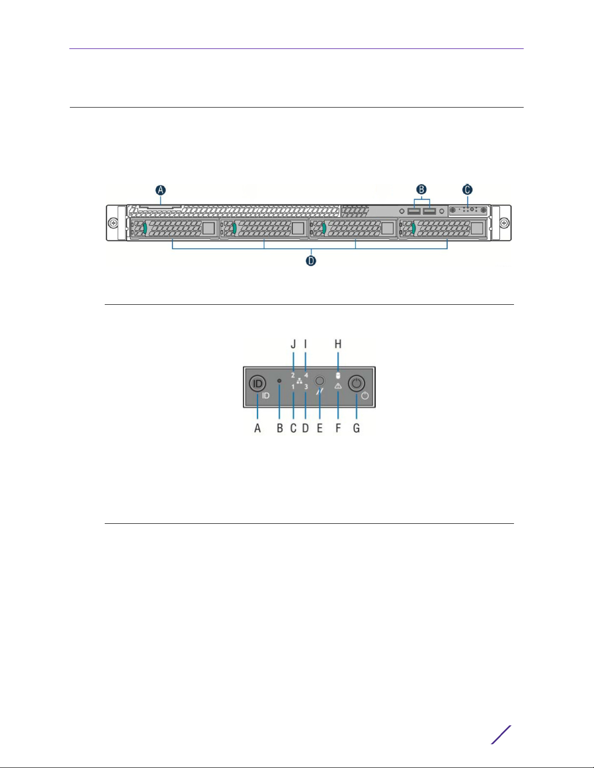
Front Panel Features
Figure 1 shows the PV-A-300 appliance front panel features. Figure 2 shows the front
control panel.
Figure 1: PV-A-300 Front Panel Features
Front Panel Features
A
System Label Pull-out
B
USB 2.0 Ports
Figure 2: Front Control Panel
A System ID Button w/Integrated LED
B
NMI Button (recessed, tool required for
use)
C
Mgmt Port Activity LED
D
Not used
E
System Cold Reset Button
C
Front Control Panel (see Figure 2)
D
Hard Disk Drive Bays
F
System Status LED
G
Power Button w/Integrated LED
H
Hard Drive Activity LED
I
Not used
J
Not used
Purview PV-A-300 Appliance Installation Guide
7
Hard Drive LED Indicator Patterns
The hard drive has two LED indicators visible from the front of the system — one is a green
LED for disk activity, and the other is amber and indicates hard drive status. The LEDs have
the following states, as described in Tab l e 3 and Tab le 4 .
Table 3: Hard Drive Activity LED Indicator Patterns
Hard Drive Condition Activity LED Patterns
Power on and drive spinning up or spinning down Off
Power on with drive activity Blinking green
Table 4: Hard Drive Status LED Indicator Patterns
Hard Drive Condition Status LED Patterns
No access or no fault Off
Hard drive fault has occurred Solid amber
Hard Drive LED Indicator Patterns
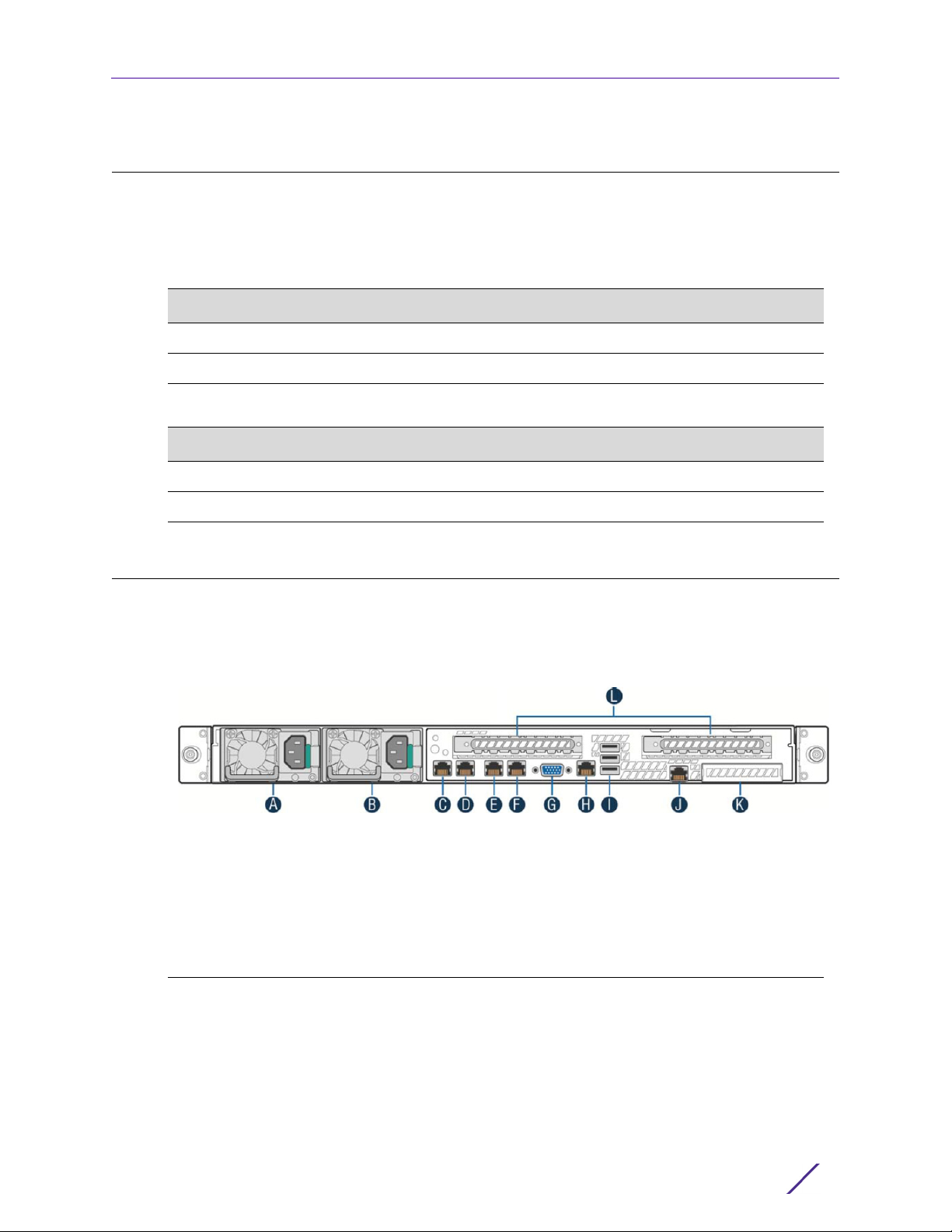
Back Panel Features
Figure 5 shows the PV-A-300 appliance back panel.
Table 5: PV-A-30 0 Bac k Pan e l
A Power Supply Module #1
B
Power Supply Module #2
C
eth0, Mgmt Port, 1 GbE RJ45
D
eth1
E
eth2
F
eth3
Ta bl e 6 describes the LEDs for the RJ45 management port.
G
Video Connector
H
Not used
I
USB 2.0 Ports
J
Not used
K
Not used (Used if PV-A-300-10G-UG is
installed)
L
Not used
Purview PV-A-300 Appliance Installation Guide
8

Power Supply Status Indicator Patterns
Table 6: RJ45 Port LEDs (Management Port)
LED Type LED Pattern Status Indication
Network Speed (Right) Off 10 Mbps
Amber 100 Mbps
Green 1000 Mbps
Link Activity (Left) Off No link
Solid Green Active link
Blinking Green Data traffic activity
Power Supply Status Indicator Patterns
The appliance has two power supplies, supplying hot-pluggable power redundancy. The
system distributes the power load across both power supplies to maximize efficiency.
Each power supply has a single bi-color LED to indicate power supply status, as described
in Ta b le 7 .
I
Table 7: Power Supply Status LED Indicator Patterns
Power Supply Condition LED Pattern
Output on and OK Green
No AC power to all power supplies Off
AC present / Only 12VSB on (PS off) or PS in cold redundant state 1Hz Blinking Green
AC power cord unplugged or AC power lost. With a 2nd PS in parallel
Amber
still with AC input power
Power supply warning events where PS continues to operate — high
temp, high power, high current, slow fan
Power supply critical event causing a shutdown, failure, OCP, OVP, fan
1Hz Blinking
Amber
Amber
fail
Power supply firmware updating 2Hz Blinking Green
Purview PV-A-300 Appliance Installation Guide
9
 Loading...