


Packet Over SONET
Module Installation and
User Guide
Extreme Networks, Inc.
3585 Monr oe Street
Santa Clara, California 95051
(888) 257-3000
http://www.extremenetworks.com
Published: June 2001
Part number: 100080-00 Rev. 02

©2001 Extreme Networks, Inc. All rights reserved. Extreme Networks and BlackDiamond are
registered trademarks of Extreme Networks, Inc. in the United States and certain other jurisdictions.
ExtremeWare, ExtremeWare Vista, ExtremeWorks, ExtremeAssist, ExtremeAssist1, ExtremeAssist2,
PartnerAssist, Extreme Standby Router Protocol, ESRP, SmartTraps, Alpine, Summit, Summit1,
Summit4, Summit4/FX, Summit7i, Summit24, Summit48, Summit Virtual Chassis, SummitLink,
SummitGbX, SummitRPS, and the Extreme Networks logo are trademarks of Extreme Networks, Inc.,
which may be registered or pending registration in certain jurisdictions. The Extreme Turbodrive logo
is a service mark of Extreme Networks, which may be registered or pending registration in certain
jurisdictions. Specifications are subject to change without notice.
All other registered trademarks, trademarks, and service marks are property of their respective owners.
ii

Contents
Preface
Introduction xiii
Terminology xiv
Conventions x iv
Related Publications xv
1Overview
BlackDiamond 6800 Series Switch Overview 1-1
BlackDiamond I/O Modules 1-2
About the PoS Modules 1-3
Physical Description 1-4
Feature Summary 1-7
Function Summary 1-9
Service Provider Features 1-11
2 Installing or Replacing a PoS Module
Preparing for Install ation 2-1
Software and Hardware Version Requirements 2-2
Cables and Connectors 2-3
Safety Information 2-4
Tools 2-5
I/O Module Slot Locations 2-5
Contents iii

Inserting and Securing a Module 2-7
Making Network Interface Cable Connections 2-9
Verifying the Module Installation 2-10
LED Indicators 2-10
Displayed Slot Status Inf ormation 2-10
Troubleshooting 2-11
Identifying Problem Categories 2-12
Fixing Configuration Errors 2-13
Upgrading the Switch Software Image 2-14
Upgrading the PoS Module S oftware Image 2-14
Fixing Power-Related Problems 2-15
Fixing Link Down P roblems 2-15
Identifying Conditions f or Replacing an I/O Mo dule 2-16
Removing and Replacing an I/O Module 2-16
Tools and Equipment 2-16
Removing an I/O Module 2-17
3 Configuring the PoS Module
Basic PoS Module Configuration Information 3-2
Default PoS Module Config urations 3-2
PoS Port Configuration an d Default VLAN Assignmen ts 3-3
Default Configuration : Bridging Over PoS Ports 3-3
Routing Over PoS Ports 3-6
Automatic Protection Switching 3-7
Configuring and Monitoring SONET Ports 3-12
Commands for Configuring and Monitoring SONET Ports 3-13
Configuring SONET Framing 3-13
Configuring SONET Clocking 3-14
Configuring the Signal F ail Threshold 3-14
Configuring the Signal De grade Threshold 3-15
Configuring the Section Trace Identifier 3-15
Configuring the Path Trace Identifier 3-16
Configuring the Signal Label 3-17
Resetting SONET Config uration Parameter Values 3-17
Displaying SONET Port St atus Information 3-18
iv Contents

SONET Events 3-19
Configuring and Monitoring PPP Functions 3-22
PPP Background Information 3-22
Commands for Configuring and Monitoring PPP Functions 3-26
Configuring the PoS Checksum 3-27
Configuring PoS Scramblin g 3-27
Configuring Link Maintenance 3-28
Configuring PPP Link Q uality Monitoring 3-29
Configuring PPP Authenti cation 3-30
Configuring the Name and Password for the Port 3-30
Creating an Authentication Database Entry 3-31
Configuring the Network Control Protocol 3 -33
Configuring the MPLS Control Protocol 3-34
Configuring the Delayed-Down -Time Interval 3-35
Displaying PPP Informa tion 3-36
Resetting PPP Configuration P arameter Val ues 3-37
Configur ing VLAN -Related Attribut es 3-38
Summary of V LAN-Relat ed Command s 3-38
Configuring Tagged VLAN 802. 1p and 802.1 Q Functions 3-39
Generic VLAN Registration Protocol Functions 3-42
Configuring Forwarding Database Attributes 3-42
Configuring Spanning Tree Attributes 3-42
Configuring QoS Functions 3-43
Summary of QoS-Related Commands 3-43
Configuring a QoS Profile 3-44
Classification and Replacement Po licies 3-46
Configuring DiffServ 3-47
Enhanced RED Support 3-51
QoS Monitor 3-59
Intra-Subnet QoS 3-59
Configuring and Monitoring Flow Statistics 3-60
Flow Statistics Background Information 3-60
Collection Port and Filtering Opti ons 3-63
Collection Architecture Scalability and Reliabili ty 3-64
Export Criteria 3-64
Commands for Configuring a nd Monitoring Flow Statistics 3-65
Contents v

MIB Support for Flow Statistics 3-74
Configuring and Monitoring APS Functions 3-75
APS Network Configuration Options 3-77
Sample Line-Switching Scenario 3-79
APS Benefits 3-82
Commands for Configuring and Monitoring APS 3-86
Enabling and Disablin g APS 3-87
Creating and Deleting an APS Group 3-87
Adding a Port to an APS Group 3-88
Deleting a Port from an APS Group 3-89
Configuring APS Authenticati on 3-89
Configuring Nonrevertive or Revertive Mode 3-90
Configuring APS Timers 3-91
Configuring APS Lockout 3-92
Configuring Forced Switch Mode 3-92
Configuring Manual Sw itch Mode 3-93
Resetting APS Group Configuration Parameters 3-94
Displaying APS Group Statu s Information 3-95
MIB Support for APS 3-96
Configuring Port Tunneling 3-97
Configuring the PoS Port Tunnel 3-98
Configuring the Ethernet Mod ule 3-99
Configuring the MPLS tls-Tunnel 3-100
Additional PoS Module Support Topics 3-101
Configuring General Switch Attribut es 3- 101
Configuring Port Attributes 3-102
Configuring IGMP Attributes 3-1 05
Configuring Layer 2 and 3 Switching Attributes 3-105
Configuring Access List Attrib utes 3-106
Changing Image and Configuration Attributes 3-106
A ExtremeWare Command Compatibility Information
Related to the PoS Module
New Commands A-1
New ExtremeWare Commands A-2
Changed Commands A-5
vi Contents

Commands and Functions Not Supported A-8
B Supported MIBs and Standards
SONET/SDH Support B-2
Standards Supported for SONET/SDH B-2
MIBs Supported for SONET/SDH B-2
PPP Support B-2
Standards Supported for PPP B-2
MIBs Supported for PPP B-3
QoS and DiffServ Support B-3
Standards Supported for DiffServ B-3
Flow Statistics Support B-4
MIBs Supported for Flow Statistics B-4
Automatic Protection Switching Support B-4
Standards Supported for APS B-5
MIBs Supported for APS B-5
Index
Index of Commands
Contents vii

viii Contents

Figures
1-1 PoS module 1-4
1-2 Front panel views of the P3cSi an d P3cMi modules 1-6
1-3 Front panel views of the P12c Si and P12cMi modules 1-7
2-1 Slot locations in a BlackDiamond 6800 series chassis 2-6
2-2 Inserting and securing a PoS module 2-8
3-1 Default configuration for BCP 3-4
3-2 IPCP configuration 3-6
3-3 APS configuratio n, port redundancy 3-8
3-4 APS configuration, module redunda ncy 3-9
3-5 APS configuration for switch redundancy 3-10
3-6 View of logical connectivity to PoS ports with IP CP enabled 3-24
3-7 View of logical connectivity to PoS ports with BCP enabled 3-25
3-8 Comparisons of RED and WRED operation 3-53
3-9 Format of NetFlow export data gram 3-61
3-10 NetFlow Collection Architecture Example 3-63
3-11 Linear 1+1 APS architecture 3-75
3-12 Linear 1+1 APS architecture with two switches 3-76
3-13 Virtual APS router configuration 3-78
3-14 Logical PPP connectivity to virtual A PS router 3-79
3-15 Format of SONET K1 and K2 Bytes 3-80
3-16 Typical redundant switch configuration without APS 3-82
3-17 Redundant switch configuration with APS 3-83
3-18 APS configuration providing faster recovery from
line failure 3-84
3-19 APS in bridging configura tion 3-85
3-20 Port tunneling via a PPP lin k 3-98
Figures ix

x Figures

Tables
1 Notice Icons xiv
2 Te xt Co n ve nt io ns x v
2-1 PoS Module and Port LEDs 2-12
3-1 SONET Parameters and Values 3-5
3-2 SONET Port Commands 3- 13
3-3 Summary of SONET Statistics 3-18
3-4 SONET Events 3-19
3-5 PPP Commands 3-26
3-6 VLAN-related Commands 3-38
3-7 QoS-Related Commands 3-43
3-8 Default Code Point-to-QoS Profile Ma pping 3-48
3-9 Assured Forwarding Classes and Three-Level
Drop Precedence 3-56
3-10 Assured Forwarding Classes and Two-Level
Drop Precedence 3-56
3-11 Mapping PHBs to QoS Profiles 3-56
3-12 NetFlow Vers ion 1 Record Format 3-60
3-13 Format of NetFlow Version 1 Export Datag ram Header 3-62
3-14 Flow Statistics Comm ands 3-65
3-15 APS Protocol for Switch from Working Line to
Protection Line 3-81
3-16 APS Commands 3-86
3-17 Changes to General Switch Commands 3-101
3-18 Changes to Port Commands 3-103
3-19 Changes to Image Commands 3-106
A-1 New ExtremeWare Commands A-2
Tables xi

A-2 Summary of Co mmands with E nhanced Syn tax A-5
A-3 Summary of Commands with A ugmented Implementation A-6
A-4 Summary of Commands Not Supported for PoS Ports A-8
xii Tables

Preface
This Preface provides an overview of this guide, describes guide conventions, and lists
other publications that may be useful.
Introduction
This guide provides the required information t o install the PoS module in a
®
BlackDiamond
module configuration t asks.
This guide is intended for use by network administrators who are responsible for
installing and setting up n etwork equipment. It assumes a ba sic working knowledge of:
• Local area networks (LANs).
• Ethern et conc epts.
• Ethernet switching and bridging concepts.
• Routing concepts .
• Internet Protocol (IP) co ncepts.
• Routing Information Protocol (RIP) and Open Shortest Path First (OSPF).
• Simple Network Managemen t Protocol (SNMP).
If the information i n the release notes shipp ed with your module diffe rs from the
information in this guide, follow the release no tes.
6800 series switch from Extreme Networks and perform th e initial
Packet Over SONET Module Installation and User Guide xiii
Terminology
When features, functionality, or operation is specific to o ne of the PoS modules, th e
specific module name is used. E xplanations about feat ures and operations that are the
same across all of the P oS modules simply refer to the product as the “module.”
Switches and switch modules t hat use naming convention s ending in “i” have
additional capabilities that are documented throughout this user guide. For the most
current list of products supporting the “i” chipset, consult you r release notes.
Unless otherwise specified, a fe ature requiring the “i” chipset requires the use of both
an “i” chipset-based management module, such as the MSM64i, and an “i”
chipset -based I /O modu le, such as the G 8Xi.
Conventions
Table 1 and Table 2 list conventions that are used throughout this guide.
Table 1: Notice Icons
Icon Notice Type Alerts you to...
Note Important features or instructions.
Caution Risk of personal injury, system damage, or loss of data.
Warning Risk of severe personal inju ry.
xiv Packet Over SONET Module Installation and User Guide

Related Publications
Table 2: Text Conventions
Convention Description
Screen displays This typeface indicates command syntax, or represents information
as it appears on the screen.
Screen displays
bold
The words “enter”
and “type”
[Key] names Key names are written with brackets, such as [Return] or [Esc].
Words in italicized type Italics emphasize a point or denote new terms at the place where
This typeface indicates how you would type a particular command.
When you see the word “enter” in this guide, you must type
something, and then press the Return or Enter key. Do not press the
Return or Ente r key when an inst ruction simpl y says “type.”
If you must press two or more keys simultaneously, the key names
are linked with a plus sign (+). Example:
Press [Ctrl]+[Alt]+[Del].
they are defined in the text.
Related Publications
The publications related to this one a re:
• ExtremeWare
• ExtremeWare Software User Guide
• BlackDiamond 6800 Series Switch Hardware Installation Guide
• BlackDiamond Module Installation Note
Documentation for Extreme Networks products is available on t he World Wide Web at
the following location :
http://www.extremenetworks.com/
™
release n otes
Packet Over SONET Module Installation and User Guide xv

xvi Packet Over SONET Module Installation and User Guide

1
Overview
The Packet over SONET (PoS) modules are I/O modules for the BlackDiamond 6800
series chassis-based s ystem. These modules con nect a BlackDiamond 6 800 series switch
to the SONET infrastructure used by metropolitan area service providers and operators
of server co-loc ation networks.
This chapter includes information on the following topics:
• BlackDiamond 6800 Series Switch Overview on page 1-1
• About the PoS Modules o n page 1-3
BlackDiamond 6800 Series Switch Overview
The BlackDiamond 6800 series switch i s a chassi s-based sw itch designed to be placed in
the core of your network. The BlackDiamond 6 800 series switch is flexible and scalable,
making it easy for you to meet the changing requirements of your network. The
™
combination of B lackDiamond, Alpine
end-to-end network solut ion that provides a nonblocking architecture, wire-speed
switching, wire-speed IP routing, and poli cy-based Quality of Service ( QoS).
Packet Over SONET Module Installation and User Guide 1-1
, and Summit™ switches delivers a consistent

Overview
BlackDiamond I/O Modules
In addition to the PoS modules described in this guide, the BlackDiamond 6800 series
switch supports a variety of I/O modules that offer a choice of port connections over
different media types and distances. For more information, see the BlackDiamond 6800
Series Switch Hardwa re Installation Guide.
BlackDiamond 6800 series I/O modules can be inserted or removed at an y time,
without causing disruption of network services. No configuration information is stored
on the I/O modules; all con figuration information is stored on the MSM64i modules.
When the BlackDiamond 6800 series switch is powered on, the ExtremeWare software
determines which slots are occupied by I/O modu les, determines whether it has a
configuration for each module, and generates a default configuration for each slot that
is occupied by an I/O module that has not yet been configured. The default
configuration is the minima l set of configuration param eter settings that will a llow the
I/O module and its ports to function. The default configuration for the I/O m odule is
not preserved unless you explicitly save the information to nonvolatile RAM (NVRAM).
You can also use E xtremeWare commands to configure the I/O module a fter installin g it
in the BlackDiamond chass is, or you can preconfigure the parameters of a module that
has not yet been inserted into the cha ssis.
If you preconfigure a slot for a particul ar modu le, the preconfigured inform ation is used
when the module is inserted. You must select a module type for the slot before you can
preconfigure the parameters. If you have preconfigured a slot for a specific module type
and then insert a different type of module, you must explicitly overwrite the existing
configuration with a new configuration, or use the ExtremeWare
slot <slot>
command to clear the existing slot conf iguration. If you enter a new
unconfig
configuration for the new module, the module uses that configuration. If you clear the
slot configuration, the new module type can use the default configuration ExtremeWare
creates.
For information on configuring I/O module s, see the ExtremeWare Software User
Guide.
1-2 Packet Over SONET Module I nstallation an d User Guid e

About the PoS Mo dules
About the PoS Modules
Two k ey applications for the PoS mo dules are: interconnecting metropolitan area
networks across the SONET network infrastructure, and interconnecting server
co-location network sites d irectly using SONET links.
In the first application, the metropolitan area network service provider can build service
network sites in various cities, then use PoS modules in a BlackDiamon d 6800 series
switch to connect those cities to a carrier ’s SONET infra structure.
In the second application, o perators o f server co-locatio n networks can u se PoS modules
in BlackDiamond 6800 series switches to create a SONET-based connection between
server co-location sites. The result is that their network is simpler to manage, and
problems can be isolated and resolved more expediently.
Extreme Networks offers the PoS module in the following co nfigurations:
• P3cMi: four OC-3 multimode, sh ort-reach optical interfaces
• P3cSi: four OC-3 single-mode, intermed iate-reach optical interfaces
• P12cMi: two OC-12 multimode, sh ort-reach optical interfaces
• P12cSi: two OC-12 single-m ode, intermediate-reach optical int erfaces
The “c” in the names o f the modules indi cates that the optica l interfaces on
these modules ope rate in concatenated mode, w hich enables all the ban dwidth
to be devoted to a si ngle payload stream.
The P3cMi (multimode version) operates in the 1310 nanometer (nm) wavelength
window at a typica l maximum cable distance of 2 kilometers (km) or 1.24 miles (mi).
The P12cMi (multimode version) also operates in the 1310 nanometer (nm ) wavelength,
but at a typical maximum cable distance of 500 meters (m) or 0.31 (mi). The P3cSi and
P12cSi (singl e-mode ver sions) also o perate in th e 1310 nan ometer (nm) w avelength
window, but at a typi cal maximum cable distance of 15 km or 9.32 (mi). All four
versions of the PoS module use industry-standard duplex SC optical fiber connectors.
Packet Over SONET Module Installation and User Guide 1-3
Overview
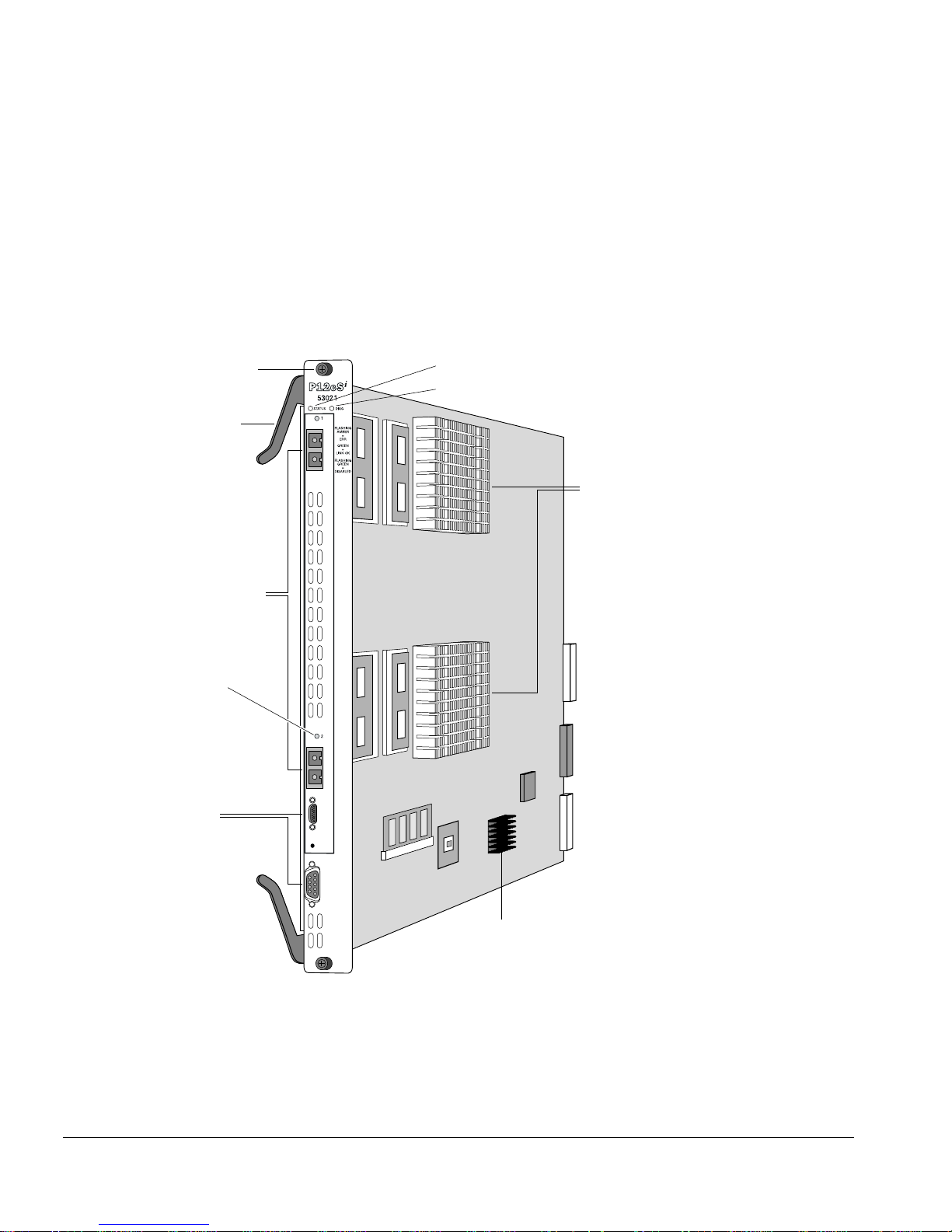
Physical Description
The PoS module con sists of a printed circuit board mounted on a metal carrier that acts
as the insertion vehicle in a BlackDiamond 6800 series switch (see Figure 1-1). The
module carrier also includes ejector/ injector handles and captive retaining screws at
each end of the module front panel. The module o ccupies one slot in a BlackD iamond
6800 serie s switch.
Captive
retaining screw
Ejector/injector
handle
Network interface ports
Two on OC-12 PoS module
Four on OC-3 PoS module
Port status LED
(one per port)
Module status LED
Module diagnostics LED
Network processors
and heat sinks
Service ports
Figure 1-1: PoS module
1-4 Packet Over SONET Module I nstallation an d User Guid e
General Purpose Processor (GPP)
PoS_002

About the PoS Mo dules
The PoS module has the following key components:
• Two high-performance network processors
• A General Purpose Processor (GPP) subsystem
The network processors are programmable devices that partici pate with the Extreme “i”
chipset to support expanded functio nality, features, and fl exibility.
The GPP subsystem ha ndles system control and I/ O module managem ent functions.
The GPP subsystem resides outside of the I/O mo dule data path to optimize
performance.
PoS Module LED Indicators
The PoS modules are equipped with two module-level LED indicators (STATUS and
DIAG) and one port-level LED indicator for each network interface port on the PoS
module (see Figure 1-2 and Figure 1-3).
The STATUS LED indicator is located near the top end of the PoS m odule front panel,
near the ejector/injector handle. This LED indicator is a bi-color LED (displaying in
either green or amber) that signals the operating status of the module as a whole.
The DIAG LED indicator is located beside the STAT US LED. This LED is a single-color
LED (displaying in amb er only) tha t flashes amber when diagnos tics are running on th e
module, and is solid amber if the module fails the diagnostics.
The port-level LED is an LED next to the port number identifying each fiber optic
network interface connector on the front panel of the module. The po rt LED is a bi-color
LED (displaying in eit her green or amber) that signals the opera ting status of that
network interface port.
For more information on PoS module LED states an d their use in troubleshooting Po S
module problems, see “Verifying the Modu le Installation” on p age 2-10.
Service Ports
The PoS modules are equipped with two front-panel service ports: one port is a
subminiature DB-9 connector; the other is a micro HD- 15 connector (see Figure 1-1).
Both ports are reserved for use only by Extreme Networks technical support personnel
for diagnostic purposes.
Packet Over SONET Module Installation and User Guide 1-5
Overview
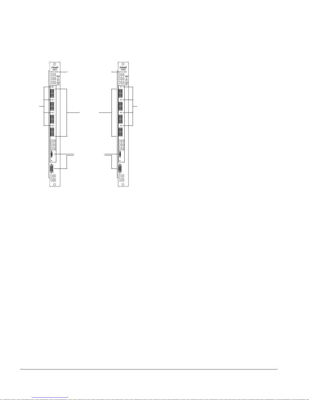
Module status LEDs
Port
status
LEDs
Network
Port
status
LEDs
interface
ports
Service ports
BD_P3
Figure 1-2: Front panel views of the P3cSi and P 3cMi modules
1-6 Packet Over SONET Module I nstallation an d User Guid e
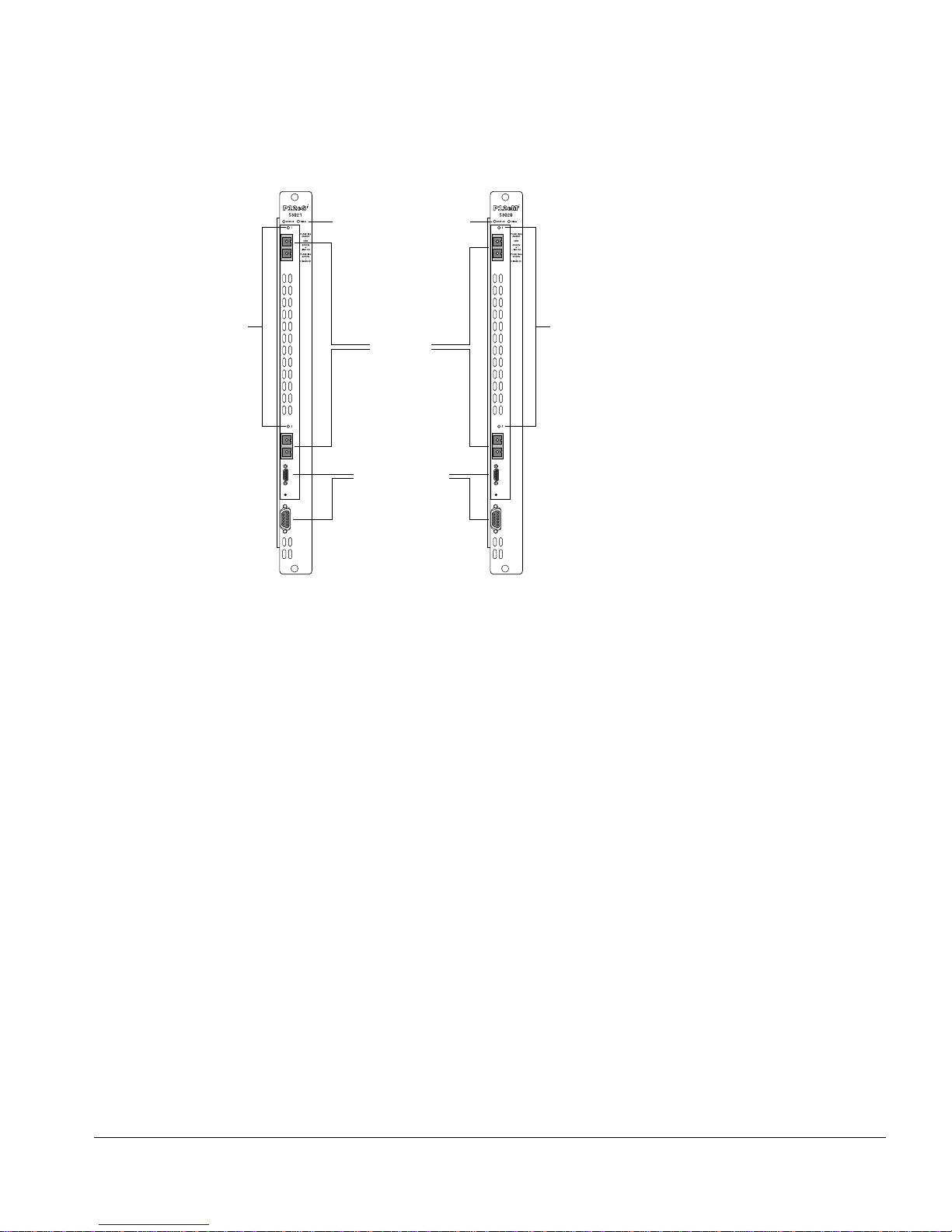
Module status LEDs
About the PoS Mo dules
Port
status
LEDs
Network
interface
ports
Service ports
Port
status
LEDs
BD_P12
Figure 1-3: Front panel views of the P12cSi and P12cM i modules
Feature Summary
The PoS modules provide the follow ing key networking funct ions:
• Support for both Synchronous Optical Netw ork (SONET) and Synchronous Digital
Hierarchy (SDH) modes of operation
• Support for the Point-to-Point Protocol (PPP) suite, including:
— Link Con trol Protocol (LCP)
— Link Mainte nance option for LCP
— Link Quality Report (LQR) Protocol
— Password Authenticatio n Protocol (PAP)
— Challenge Handshake A uthentication Protocol (CHAP)
— IP Control Protocol (IPCP)
— Bridging Control Protocol ( BCP)
— Extreme Disc overy Protocol Control Protocol (EDPCP)
Packet Over SONET Module Installation and User Guide 1-7

Overview
• Efficient support for IP routing over SONET via IPCP
• Support for Transparent LAN Services (TLS) over SONET via BCP
• Support for MultiProtocol L abel Switching Control Protocol (MPLS CP) via PPP
• Support for jumbo frames
• Extensive support for Quality of Service (QoS) and Differentiated Services (DiffServ),
including:
— Eight ingress queues and eight egress queues per interface
— Ingress and egress rate shapin g and limiting
— IEEE 802.1Q VLAN priorities
— Weighted RED (WR ED) congestion a voidance algorith m
— Assured Forwarding and Expedited Forwarding RFCs
• Support for service provider specific features, such as:
— Flexible remapping of DiffServ codepoints
— Flexible remapping of IEEE 802.1Q VLAN IDs
— VLAN tunneling via nested 802.1Q tags
— Port tunneling o f High-Level Data Link Control (H DLC) byte streams
• Support for NetFlow Version 1 per-flow statistics, including :
— Capacity for tw o million flow records per PoS modu le
— Scalability via d istribution to groups of flow-record collector devices
— Filters enabling s tatistics to be maintained for selected flo ws
— Aggregation option for further reducing the volume of exported data
• Resiliency with fast recovery from SONET link f ailures via support for Automatic
Protection Switching (APS) protocol in mu ltiple configurations, includ ing networks
where the working and protection lines are:
— Terminated in the same SONET mo dule
— Terminated in different SONET modules residing in the sa me BlackDia mond 6800
series system
— Terminated in different SONET modules residing in different BlackDiamond 6800
series systems
1-8 Packet Over SONET Module I nstallation an d User Guid e

About the PoS Mo dules
Function Summary
The following sections provide brief descriptio ns of the key functions provided by t he
PoS modules. Each of these sections is expanded into greater detail in Chapter 3.
SONET and SDH
SONET and SDH are the two terms used to identify a time division multiplexing
technology that is optimize d for transporting voice traffic across a digital optical
network, but that is also capable of providing high-speed capacity for transporting data.
The term SONET is used to identify the technolog y used within the North American
digital network. Its standa rds are published by Bellcore and the American National
Standards Institute (ANSI). The term SDH is used to identify the equivalent standard
approved by the International Telecommunication Union (ITU) for use in Europe and
elsewhere in the global digital network. Because SDH evolved out of SONET, the two
standards are closely joined and have been widely accepted as a dominant choice for
implementations requiring high trans port capacity and resistance to failure.
PPP
PPP encompasses a s uite of protocols designed to provide standard methods for
transporting datagram s over point-to-point l inks. The use of PPP over SONET links is
commonly referred to as Packet over SONET, or PoS. The Extreme Networks
implementation of P PP for the PoS m odule provides s upport for the f ollowin g protoco ls
in the PPP suite:
• Link Control Protocol (LCP)
• Link Quality Report (LQR) Protocol
• Challenge Handshake Authentication Protocol (CHAP)
• Password Authentication Protocol (PAP)
• IP Control Protocol (IPCP)
• Bridging Control Protocol (BCP)
• Extreme Discovery P rotocol Control Protocol (ED PCP)
MPLS
The PoS module ports provide MPLS support via a PPP link. The MPLS Control
Protocol (MPLSCP) allows MPLS labeled packets to be transported across a PPP lin k.
Packet Over SONET Module Installation and User Guide 1-9

Overview
MPLS labeled packets can also be encapsulated in Ethernet headers and transported
across a PPP link using BCP.
Jumbo Frames
The PoS module ports provide jumbo frame support that is similar to that provided by
Ethernet ports on a BlackDiamond 6800 series switch.
Jumbo frames are Ethernet frames that are larger than 1522 bytes, including four bytes
used for the cyclic redundancy check (CRC). Extreme products that use the “i” chipset
support switching and routing of jumbo frames at wi re-speed on all ports.
Jumbo frames are used between endstations that support larger frame sizes for more
efficient transfers of bulk data. Both endstations involved in t he transfer must be
capable of supporting jumbo frames.
QoS and Differentiat ed Serv ices
The PoS modules support eight ingress queues and eight egress queues per port. The
scheduling parameters for these queues (minimum bandwidth, maximum bandwidth,
priority level, etc.) are controlled by QoS profiles that you can customize f or individual
ingress or egress queues on a specific PoS port.
You can assign frames to queues based on IEEE 802.1p priorities, MPLS EXP values,
Differentiated Services Code Points (DSCPs), or by co nfiguring a QoS profile for the
port or VLAN. You can tailor the DSCP-to -queue mapping for ingress or egress
directions on a per-port basis. Most of the exi sting ingress classification f unctions, along
with the DiffServ replacement functions, are also supported for PoS ports.
The supported DiffServ functions maximize u ser flexibility while providing all of th e
features needed to support the standard per-hop behaviors (PHBs), including:
• Default
• Class Selector
• Assured Forwarding
• Expedited Forwarding
The PoS modules also provide flexible suppo rt for the well-known Weighted RED
(WRED) congestion avoidance algorithm.
1-10 Packet Over SONET Module Installation and User Guide

About the PoS Mo dules
Service Provider Features
The PoS modules provide the following features for service provider environments:
• DSCP mapping
• VLAN ID (VID) tag mapping
• VLAN ID (VID) tag nesting
• Port tunneling
You can us e the
diffserv dscp-mapping command to configure a mapped relationship
between an input DSCP and an asso ciated out put DSCP. Each PoS p ort suppor ts three
DSCP mapping tables: one of the tables is used in the ingress direction; two are used for
egress flows (onto the SONET link). The two egress tables are for the congested and
noncongested states, as determined by the RED alg orithm. If RED is not enabled on the
PoS port, the egress congested-state mapping table is no t used.
In the ingress direction, the input DSCP of a packet received from the SONET link is
replaced by an output DSCP before the packet is forwarded. In the egress direction, the
operation is similar, except that the DSCP mapping occurs before the packet is
transmitted onto the SONET link.
One potential use of the DSCP mappin g capability is to reconcile varying DiffServ
policies at the boundary between autonomous systems, such as at the boundary
between two ISPs. The availability of different tables for the congested and
noncongested states is useful i n marking operations that increase the probabili ty of
packets being dropped during times of congestion, as discussed in the DiffServ Assured
Forwarding RFC (RFC 2597).
An analogous feature has been added for managing 802.1Q tags. The
dot1q tagmapping command provides support for VLAN ID (VID) mapping tables.
Each PoS port supports two VID tables: one table is used in the ingress direction; the
other is used in the egress direction. Each of the tabl es enables an input VID to be
mapped to an output VID. This feature is useful in reconciling policy differences at the
boundary between the customer and the service provider.
Another related enha ncement provides supp ort for neste d 802.1Q tags by allo wing a
tag push or tag pop attribute to be associated with a VID. The push attribute indicates that
a new tag is to be added to the frame, while the pop attribute indicates that th e top-level
tag is to be removed from the frame. This capability is augmented by a n option that
allows the 802.1p priority of the frame to be either preserved or set to a
user-configurable value when a new tag is pushed. These functions make it possible for
service providers to tunnel customer-specific VLANs a cross a common SONET
backbone in a very simple manner.
Packet Over SONET Module Installation and User Guide 1-11

Overview
The PoS module also supports port tunneling. Port tunneling can be used to
encapsulate and transport the raw High-Level Data Link Control (HDLC) encapsulated
byte stream from one PoS port to another PoS port across an MPLS network. This
allows service providers to t unnel different types of SONET H DLC streams across a
non-SONET backbone li ke Ethernet.
NetFlow Statistics
Each PoS port can maintain and export statistics for the flows that traverse the
associated SONE T link.
Per-flow statistics are useful for many mana gement purposes, including:
• Accounting and billing
• Network capacity planning a nd trend analysis
• Network monitoring
• Wo rkload charac terization
• User profiling
• Data warehousing and mining
Each PoS module can ma intain two m illion flow records. Per-flow st atistics are reported
in the NetFlow, Version 1 f ormat, which groups flow records together into UDP
datagrams for export to a flow-collector device.
The PoS module also provides a NetFlow distribution feature to provide a growth path
to more scalable and robust collection architect ures. This feature allows a single PoS
port to distribute statistics across multiple groups of flow-collector devices in a
load-balanced manner. The function also includes a health-check feature that
significantly improves the reliability of the collection a rchitecture. The health-checker
ensures that only responsive flow-collector devi ces are included in the effective export
distribution lists.
To further enh ance scalability, the PoS module also offers filters and fi lter-based
aggregation options that a llow you to configure a PoS po rt to maintain statistics
selectively for only those flow s matching specified fil ters. The aggregation options can
further reduce the volume of exported data by enabling a sin gle set of statistics to be
maintained for all the flows th at match an aggregation filter.
1-12 Packet Over SONET Module Installation and User Guide

About the PoS Mo dules
Automatic Protection Switching
Automatic Protection Switching, or A PS, is a physical-layer resiliency featu re specified
in the SONET standards. Multiplex Section Protection, or MSP, is the APS equivalent in
the SDH standard, which is also supported by the PoS module. Throughout this guide,
the terms APS and Automatic Protection Switching are used to refer to the protection
switching features of both s tandards.
Of the various protection switching modes specified in the SONET/SDH standards, the
BlackDiamond 6800 series sw itches use the linear 1+1 architecture to protect tributary
SONET lines. In the linear 1+1 architecture, there is one protection line for each working
line. If the working line fails, traffic is automatically switched to the protection line. You
can also control whether traffic switched to the protection line is automatically s witched
back to the working line when i t is restored to service.
The Extreme Networks implementation supports network configurations wh ere:
• Workin g and protection lines are terminated in the same P oS module.
• Workin g and protection lines are terminated in different PoS modules residing in th e
same BlackDiamond 6800 series switch.
• Workin g and protection lines are terminated in different PoS mod ules residing in
different BlackDiamond 6800 series switches.
Packet Over SONET Module Installation and User Guide 1-13

Overview
1-14 Packet Over SONET Module Installation and User Guide
 Loading...