

Extreme Networks ExtremeWare Version 7.8 Troubleshooting Manual

Advanced System
Diagnostics and
Troubleshooting Guide
ExtremeWare Software Version 7.8
Extreme Networks, Inc.
3585 Monroe Street
Santa Clara, California 95051
(888) 257-3000
http://www.extremenetworks.com
Published: May 2008
Part number: 1 00279-00 R ev 01

©2005 Extreme Networks, Inc. All rights reserved. Extreme Networks, ExtremeWare, Alpine, and BlackDiamond are
registered trademarks of Extreme Networks, Inc. in the United States and certain other jurisdictions. ExtremeWare Vista,
ExtremeWorks, ExtremeAssist, ExtremeAssist1, ExtremeAssist2, PartnerAssist, EPICenter, Extreme Standby Router
Protocol, ESRP, SmartTraps, Summit, Summit1i, Summit5i, Summit7i,Summit48i, Summit48si, SummitPx, Summit 200,
Summit Virtual Chassis, SummitLink, SummitGbX, SummitRPS and the Extreme Networks logo are trademarks of
Extreme Networks, Inc., which may be registered or pending registration in certain jurisdictions. The Extreme
Turbodrive logo is a service mark of Extreme Networks, which may be registered or pending registration in certain
jurisdictions. Specifications are subject to change without notice.
NetWare and Novell are registered trademarks of Novell, Inc. Solaris is a trademark of Sun Microsystems, Inc. F5,
BIG/ip, and 3DNS are registered trademarks of F5 Networks, Inc. see/IT is a trademark of F5 Networks, Inc.
“Data Fellows”, the triangle symbol, and Data Fellows product names and symbols/logos are
trademarks of Data Fellows.
F-Secure SSH is a registered trademark of Data Fellows.
All other registered trademarks, trademarks and service marks are property of their respective owners.
2

Contents
Preface
Introduction 9
Terminology 9
Conventions 9
Related Publications 10
Chapter 1 Introduction
Introduction 11
Diagnostics: A Brief Historical Perspective 12
Overview of the ExtremeWare Diagnostics Suite 12
Supported Hardware 13
Applicable ExtremeWare Versions 13
Chapter 2“i” Series Switch Hardware Architecture
Diagnostics Support 15
The BlackDiamond Systems 16
BlackDiamond 6800 Series Hardware Architecture Differences 16
The BlackDiamond Backplane 17
BlackDiamond I/O Modules 18
Management Switch Modules 19
BlackDiamond MSM Redundancy 20
Causes of MSM Failover and System Behavior 20
Alpine Systems 22
Summit “i” Series Systems 23
Chapter 3 Packet Errors and Packet Error Detection
Overview 25
Advanced System Diagnos tics and Troubleshooting Guide 3

Contents
Definition of Terms 26
Standard Ethernet Detection for Packet Errors on the Wire 27
Extreme Networks’ Complementary Detection of Packet Errors Between Wires 27
Hardware System Detection Mechanisms 28
Software System Detection Mechanisms 29
Failure Modes 30
Tra n si e nt F ai l ure s 30
Systematic Failures 30
Soft-State Failures 30
Permanent Failures 31
Responding to Reported Failures 31
Health Check Messages 33
Alert Messages 33
Checksum Error Messages: 34
Corrective Behavior Messages 35
Chapter 4 Software Exception Handling
Overview of Software Exception Handling Features 37
System Watchdog Behavior 37
System Software Exception Recovery Behavior 38
Redundant MSM Behavior 38
Configuring System Recovery Actions 40
Related Commands 40
Configuring System Recovery Actions on “i” Series Switches 40
Configuring System Recovery Actions on “e” Series Switches 41
Usage Notes 41
Configuring Reboot Loop Protection 43
Related Commands 43
Configuring Reboot Loop Protection 43
Dumping the “i” Series Switch System Memory 45
Related Commands 45
Configuring an Automatic System Dump During System Recovery 45
Initiating a Manual System Dump 46
Example Log for a Software Exception 47
Chapter 5 Diagnostics
Diagnostic Test Functionality 49
How Diagnostic Tests are Run 49
How the Test Affects the Switch 50
System Health Checks: A Diagnostics Suite 52
Diagnostic Suite Components 52
The Role of Memory Scanning and Memory Mapping 53
Modes of Operation 54
4 Advanced System Diagnostics and Troubleshooting Guide

Contents
The Role of Processes to Monitor System Operation 55
Power On Self Test (POST) 56
Related Commands 56
Configuring the Boot-Up Diagnostics 56
Runtime (On-Demand) System Diagnostics 57
Runtime Diagnostics on “i” Series Systems 57
Related Commands 58
Running the Diagnostics on BlackDiamond Systems 58
Runtime Diagnostics on “i” Series Alpine and Summit Systems 58
System Impact of Running the Diagnostics on “i” Series Switches 59
Runtime Diagnostics on “e” Series Systems 59
Related Commands 60
Running the Diagnostics on Summit “e” Switches 60
System Impact of Running the Diagnostics on Summit “e” Series Switches 60
Automatic Packet Memory Scan (via sys-health-check) 60
Memory Scanning and Memory Mapping Behavior 61
Limited Operation Mode 64
Effects of Running Memory Scanning on “i” Series Switches 64
Summit, Alpine, or BlackDiamond with a Single MSM 64
BlackDiamond System with Two MSMs 64
Interpreting Memory Scanning Results 66
Per-Slot Packet Memory Scan on BlackDiamond Switches 67
Related Commands 67
Configuring the Packet Memory Scan Recovery Mode 67
System Impact of Per-Slot Packet Memory Scanning 68
Network Impact of Per-Slot Packet Memory Scanning 68
System (CPU and Backplane) Health Check 70
Health Check Packet Types 70
Backplane Health Check States 70
Related Commands 71
Health Check Functionality 71
Alarm-Level Response Action 71
Auto-Recovery Response Action 71
Backplane Health Check 72
Viewing Backplane Health Check Results—show log Command 72
Viewing Backplane Health Check Diagnostic Results—show diagnostics Command 73
Analyzing the Results 78
CPU Health Check 79
Viewing CPU Health Check Results—show log Command 79
Viewing CPU Health Check Diagnostic Results—show diagnostics Command 80
Analyzing the CPU Health Check Results 80
Transceiver Diagnostics 82
Usage Guidelines 82
Related Commands 82
Configuring the Transceiver Diagnostics 82
Advanced S ystem Diagnostics and Trouble s hooting Guide 5

Contents
System Impacts of the Transceiver Diagnostics 83
Network Impact of the Transceiver Diagnostics 83
Viewing Diagnostics Results 84
Example Log Messages for Transceiver Diagnostic Failures 84
Examples, show diagnostics Command 85
Example—show switch Command 86
Transceiver Diagnostic Result Analysis 87
FDB Scan 88
Usage Guidelines 88
Related Commands 89
Enabling FDB Scanning 89
Disabling FDB Scanning 89
Configuring the FDB Scan Diagnostics 90
System Impact of the FDB Scan Diagnostic 90
Network Impact of the FDB Scan Diagnostic 90
Viewing Diagnostics Results 91
Example Log Messages for FDB Scan Diagnostic Failures 91
Example FDB Scan Results from the show diagnostics Command 91
Example Output from the show switch command 92
Example Output from the show fdb remap Command 92
Chapter 6 Additional Diagnostics Tools
Temperature Logging for Modular Switches 93
Related Commands 93
System Impacts of Temperature Logging 94
Network Impact of Temperature Logging 94
Syslog Servers 94
Related Commands 94
Enabling Logging to Remote Syslog Server Targets 94
Disabling Logging to Remote Syslog Server Targets 95
Adding a Syslog Server 95
Deleting a Remote Syslog Server 95
System Impact of the Syslog Server Facility 95
Network Impact of the Syslog Server Facility 96
Cable Diagnostics 96
Cable Diagnostics for the High-Density Gigabit Ethernet I/O Modules in “i” Series
Switches 96
Related Commands 96
Running Cable Diagnostics 97
Viewing and Interpreting CDM Test Data 98
Cable Diagnostics for “e” Series Switches 101
Chapter 7 Troubleshooting Guidelines
Contacting Extreme Technical Support 103
Americas TAC 103
6 Advanced System Diagnostics and Troubleshooting Guide

Asia TAC 104
EMEA TAC 104
Japan TAC 104
What Information Should You Collect? 105
Analyzing Data 105
Diagnostic Troubleshooting 106
Extreme Networks’ Recommendations 107
Using Memory Scanning to Screen I/O Modules 109
Appendix A Limited Operation Mode and Minimal Operation Mode
Limited Operation Mode 111
Triggering Limited Operation Mode 112
Bringing a Switch Out of Limited Operation Mode 112
Minimal Operation Mode 112
Triggering Minimal Operation Mode 112
Bringing a Switch Out of Minimal Operation Mode 113
Contents
Appendix B Reference Documents
General Information 115
Other Documentation Resources 115
Index
Index of Commands
Advanced System Diagnos tics and Troubleshooting Guide 7

Contents
8 Advanced System Diagnostics and Troubleshooting Guide

Preface
This Preface provides an overview of this guide, describes guide conventions, and lists other
publications that might be useful.
Introduction
This guide describes how to use the ExtremeWare hardware diagnostics suite to test and validate the
operating integrity of Extreme Networks switches. The tools in the diagnostic suite are used to detect,
isolate, and treat faults in a system.
This guide is intended for use by network designers, planners, and operations staff.
Terminology
When features, functionality, or operation is specific to a modular or stand-alone switch family, the
family name is used. Explanations about features and operations that are the same across all product
families simply refer to the product as the “switch.”
Conventions
Ta bl e 1 and Table 2 list conventions that are used throughout this guide.
Table 1: No tice Icons
Icon Notice Type Alerts you to...
Note Important features or instructions.
Caution Risk of personal injury, system damage, or loss of data.
Warning Risk of severe pe rsonal injury .
Advanced System Diagnos tics and Troubleshooting Guide 9

Preface
Table 2: Text Conventions
Convention Description
Screen displays This typeface indicates command syntax, or represents information as it appears on the
screen.
The words “enter”
“type”
and
[Key] names Key names are written with brackets, such as [Return] or [Esc].
Letter in bold type Letters within a command that appear in bold type indicate the keyboard shortcut for a
Words in
italicized
type Italics emphasize a point or denote new terms at the place where they are defined in
When you see the word “enter” in this guide, you must type something, and then press
the Return or Enter key. Do not press the Return or Enter key when an instruction
simply says “type.”
If you must press two or more keys simultaneously, the key names are linked with a
plus sign ( +). Exam ple:
Press [Ctrl]+[Alt]+[Del].
command. When entering the command, you can use just the bolded letters instead of
the entire word.
the text.
Related Publications
The publications related to this one are:
• ExtremeWare Software User Guide, Software Version 7.7.
• ExtremeWare Software Command Reference, Software Version 7.7.
• ExtremeWare Error Message Decoder.
Documentation for Extreme Networks products is available on the World Wide Web at the following
location:
http://www.extremenetworks.com/services/documentation/Default.asp
10 Advanced System Diagnostics and Troubleshooting Guide

1 Introduction
This guide describes how to use the ExtremeWare hardware diagnostics suite to test and validate the
operating integrity of Extreme Networks switches. The tools in the diagnostic suite are used to detect,
isolate, and treat faults in a system.
This chapter contains the following sections:
• Diagnostics: A Brief Historical Perspective on page 12
• Overview of the ExtremeWare Diagnostics Suite on page 12
• Supported Hardware on page 13
• Applicable ExtremeWare Versions on page 13
Introduction
The purpose of this guide is to provide information and guidelines to assist you in implementing the
diagnostic suite within ExtremeWare. The Extreme Networks diagnostic software is intended to identify
possible faulty hardware or software error conditions and—depending on how the various diagnostics
features are configured—take the appropriate preconfigured action. The action might be to enable the
switch to write informative error messages to the switch log, attempt to recover itself and continue
operating, or simply remove the suspect system component from service.
It is important to note that while each diagnostic test—by itself—is not complicated, system
configuration, as a whole, must be evaluated to ensure ongoing, expected behavior both with the switch
and across the network itself. For example, in implementing the diagnostic suite, you must take into
consideration these operational variables:
• Redundancy mechanisms implemented
• Levels of redundancy within the network
• Acceptable outage windows (scheduled and unscheduled)
Advanced System Diagnos tics and Troubleshooting Guide 11

Introduction
Diagnostics: A Br ief Historical Perspective
Diagnostic utility programs were created to aid in troubleshooting system problems by detecting and
reporting faults so that operators or administrators could go fix the problem. While this approach does
help, it has some key limitations:
• It is, at its base, reactive, meaning a failure must occur before the diagnostic test can be used to look
for a cause for the failure.
• It can be time consuming, because the ability to troubleshoot a failure successfully based on the
information provided by the diagnostics test depends greatly on the types of information reported
by the test and the level of detail in the information.
Because users of mission-critical networks and network applications are becoming increasingly
dependent on around-the-clock network access and highest performance levels, any downtime or
service degradation is disruptive and costly. Time lost to an unexpected failure, compounded by more
time lost while someone attempts to isolate and fix the failure, has become increasingly less acceptable.
The process of improving diagnostic tests to minimize failures and their impact is a kind of feedback
system: What you learn through the use of the diagnostics improves your understanding of hardware
failure modes; what you learn from an improved understanding of hardware failure modes improves
your understanding of the diagnostics.
The goal of the current generation of ExtremeWare diagnostics is to help users achieve the highest
levels of network availability and performance by providing a suite of diagnostic tests that moves away
from a reactive stance—wherein a problem occurs and then you attempt to determine what caused the
problem—to a proactive state—wherein the system hardware, software, and diagnostics work together
to reduce the total number of failures and downtime through:
• More accurate reporting of errors (fewer false notifications; more information about actual errors)
• Early detection of conditions that lead to a failure (so that corrective action can be taken before the
failure occurs)
• Automatic detection and correction of packet memory errors in the system’s control and data planes
Administrators will now find a greatly reduced MTTR (mean time to repair) due to fast and accurate
fault identification. Multiple modules will no longer need to be removed and tested; faulty components
will usually be identified directly. Over time, there should be a significant reduction in the number of
problems found.
NOTE
In spite of the improved ExtremeWare hardware diagnost ics, some network events might still occur,
because software is inc apable of detecting and preventing every kind of failure.
Overview of the ExtremeWare Diagnostics Suite
The ExtremeWare diagnostic suite includes the following types of tools for use in detecting, isolating,
and treating faults in a switch. Each of these diagnostic types is summarized below, but is described in
greater detail in later sections of this guide.
• Power-on self test (POST)—A sequence of hardware tests that run automatically each time the switch
is booted, to validate basic system integrity. The POST runs in either of two modes: normal (more
thorough, but longer-running test sequence) or FastPOST (faster-running basic test sequence).
12 Advanced System Diagnostics and Troubleshooting Guide

Supporte d Hardware
• On-demand system hardware diagnostics—Run on demand through user CLI commands; runs in
either of two modes: normal (faster-running basic test sequence) or extended (more thorough, but
longer-running test sequence).
The extended diagnostics include the packet memory scan, which checks the packet memory area of
the switch fabric for defects and maps out defective blocks. This test can be run by itself, as part of
the slot-based extended diagnostics, or can be invoked from within the system health checks.
• Switch-wide communication-path packet error health checks—(Apply only to “i” series Summit,
Alpine, and BlackDiamond switches.) An integrated diagnostic subsystem—the system health check
feature—that consists of a number of different test types, operating proactively in the background to
detect and respond to packet error problems in module memory or on communication paths.
The system health checks for “i” series switches include the following kinds of tests:
— Backplane health checks
— CPU health checks
— Switch fabric checksum validation
— Dynamic memory scanning and memory mapping
— Tra n sc e iv e r d iag n os t ics
— Forwarding database (FDB) scan
NOTE
One component of the system hea lth check feature is a bus monitoring and data inte grity verification
subsystem that monito rs the operation of all data and contro l busses within the switch. This low-level
subsystem—comp osed of software and hardware c omponents—passes the r esults of its tests to
another system health check subsystem, an inte lligent layer that is responsible for interpreti ng the
test results and repo rting th em to the user. Since the inception of the use of this intelligent
interpretati on and repor ting layer in the system health check feature, the operation of this
interpretati on and repor ting subsystem has u ndergone significan t changes. At its current level of
maturity, it represents an intelligent, integral comp onent of the overall system health ch eck system.
Suppor ted Hardware
The ExtremeWare diagnostic suite applies only to Extreme Networks switch products based on the
“inferno” series chipset. Equipment based on this chipset are referred to as being “inferno” series or “i”
series products: the BlackDiamond family of core chassis switches (6804, 6808, and 6816), the Alpine
systems (3802, 3804, 3808), and the Summit “i”-series stackables (Summit1i, Summit5i, Summit7i,
Summit 48i, and Summit48Si).
A subset of the ExtremeWare diagnostic suite—runtime, slot-based diagnostics—applies only to Extreme
Networks Summit “e” series switch products. The Summit “e” series switches include the following
models: Summit
Summit
400-24t, and Summit 400-48t.
200-24, Summit 200-48, Summit 300-24, Summit 300-48, Summit 400-24p,
Applicable ExtremeWare Versions
The information in this guide is based on the features and feature attributes found in
ExtremeWare
Advanced System Diagnos tics and Troubleshooting Guide 13
Version 7.4 or later.

Introduction
14 Advanced System Diagnostics and Troubleshooting Guide

2 “
This chapter provides a brief summary of the “i” series switch hardware features most relevant to
understanding the use of the Extreme Networks diagnostic suite.
This chapter contains the following sections:
• Diagnostics Support on page 15
• The BlackDiamond Systems on page 16
• Alpine Systems on page 22
• Summit “i” Series Systems on page 23
i
” Series Switch Hardware Architecture
Diagnostics Suppor t
The ExtremeWare diagnostic suite applies only to Extreme Networks switch products based on the
“inferno” series chipset. Equipment based on this chipset are referred to as being “inferno” series or “i”
series products: the BlackDiamond family of core chassis switches (6804, 6808, and 6816), the Alpine
systems (3802, 3804, 3808), and the Summit “i”-series stackables (Summit1i, Summit5i, Summit7i,
Summit 48i, and Summit48Si).
NOTE
These switches and the switch modules us e naming conventions ending with an “i ” to identify them as
“inferno” series or “i” series produc ts. For the most current list of products s upport ing the “i” chipset,
such as the MSM-3 and other “3”-ser ies modules, such as the G16X
Unless otherwise sp ecified, a feature requiring the “i” chipset requires the use of both an “i”
chipset-based ma nagement module, suc h as the MSM64i, and an “i” chipset-ba sed I/O module, such as
the G8Xi.
3
, consult your release note s.
Advanced System Diagnos tics and Troubleshooting Guide 15
“i” Series Switch Hardware Architecture
The BlackDiamond Systems
In the context of the advanced system diagnostics suite, the BlackDiamond family of core chassis
switches share the same fundamental hardware architecture: a multislot modular chassis containing a
passive backplane that supports redundant load-sharing, hot-swappable switch fabric modules. On
BlackDiamond systems, each I/O module and MSM represents an individual switch containing its own
switching fabric and packet memory.
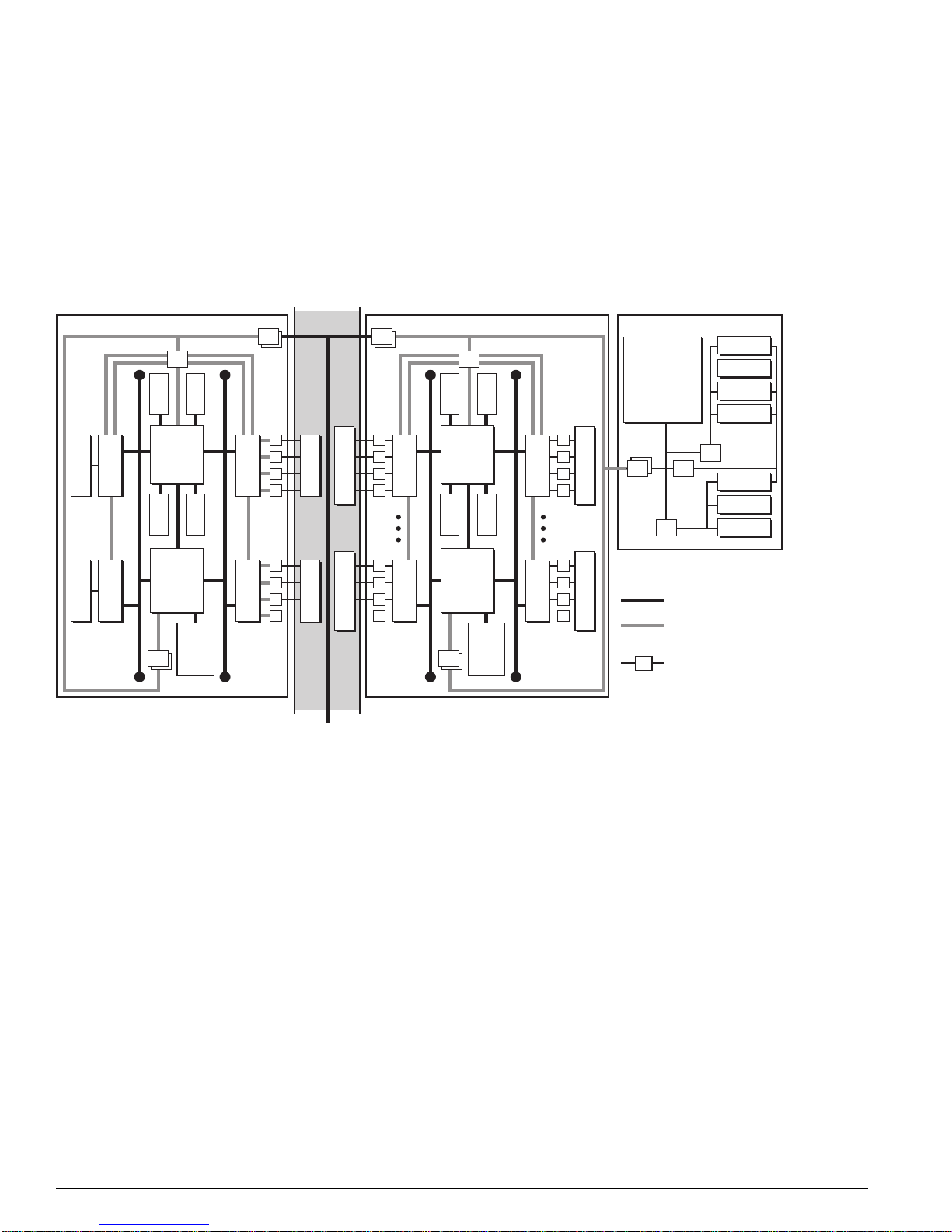
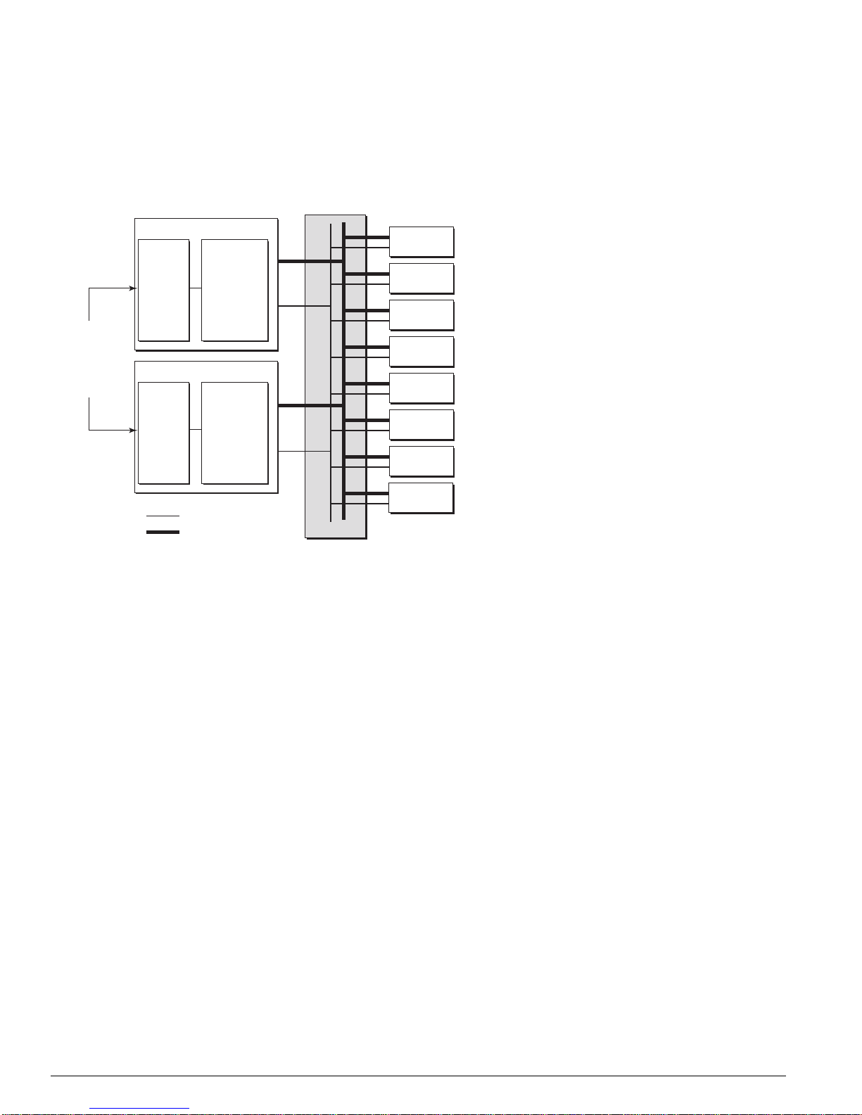
Figure 1: BlackDiamond 6800 Series a rchitecture, general block diagram
Control Bus Control Bus
NVRAM
CPLD
UART
PCMCIA
FDB
VPST
BackplaneBackplane
FDB
CPU
Subassembly
VPST
AFQM
ASIC
To PHY
To PHY
Control Bus Control Bus
(Quake)
PBus
Memory
INT MACINT MAC
(To all other slots)
To MSM-ATo MSM-B
To BackplaneTo Backplane
EXT MAC
OTP
PBus
(Twister)
EXT MAC
I/O Module (G8Xi) Master MSM (MSM-A)
PQM
SE
ASIC
Packet
MACMAC
PBus
AFQM
ASIC
(Quake)
OTP
SE
ASIC
(Twister)
PQM
Packet
Memory
PBus
MACMAC
To BackplaneTo Backplane
Master MSM Daughter Card
Control Bus
Data/Packet
Bus (PBus)
Transceiver
FLASH
SRAM
MGMT
DN_033A
BlackDiamond 6800 Series Hardware Architecture Differences
In the context of understanding the ExtremeWare diagnostics and their use in troubleshooting system
problems, these are the key hardware distinctions between the BlackDiamond 6816, 6808, and 6804.
• BlackDiamond 6816—Modular chassis with passive backplane; sixteen chassis slots for I/O modules;
four chassis slots for MSMs.
• BlackDiamond 6808—Modular chassis with passive backplane; eight chassis slots for I/O modules;
two chassis slots for MSMs.
• BlackDiamond 6804—Modular chassis with passive backplane; four chassis slots for I/O modules;
two chassis slots for MSMs.
16 Advanced System Diagnostics and Troubleshooting Guide
The BlackDiamond Sy stems
A
The BlackDiamond Backplane
The BlackDiamond backplane is a passive backplane, meaning that all the active components such as
CPUs, ASICs, and memory have been moved onto plug-in modules, such as the I/O modules and
MSMs.
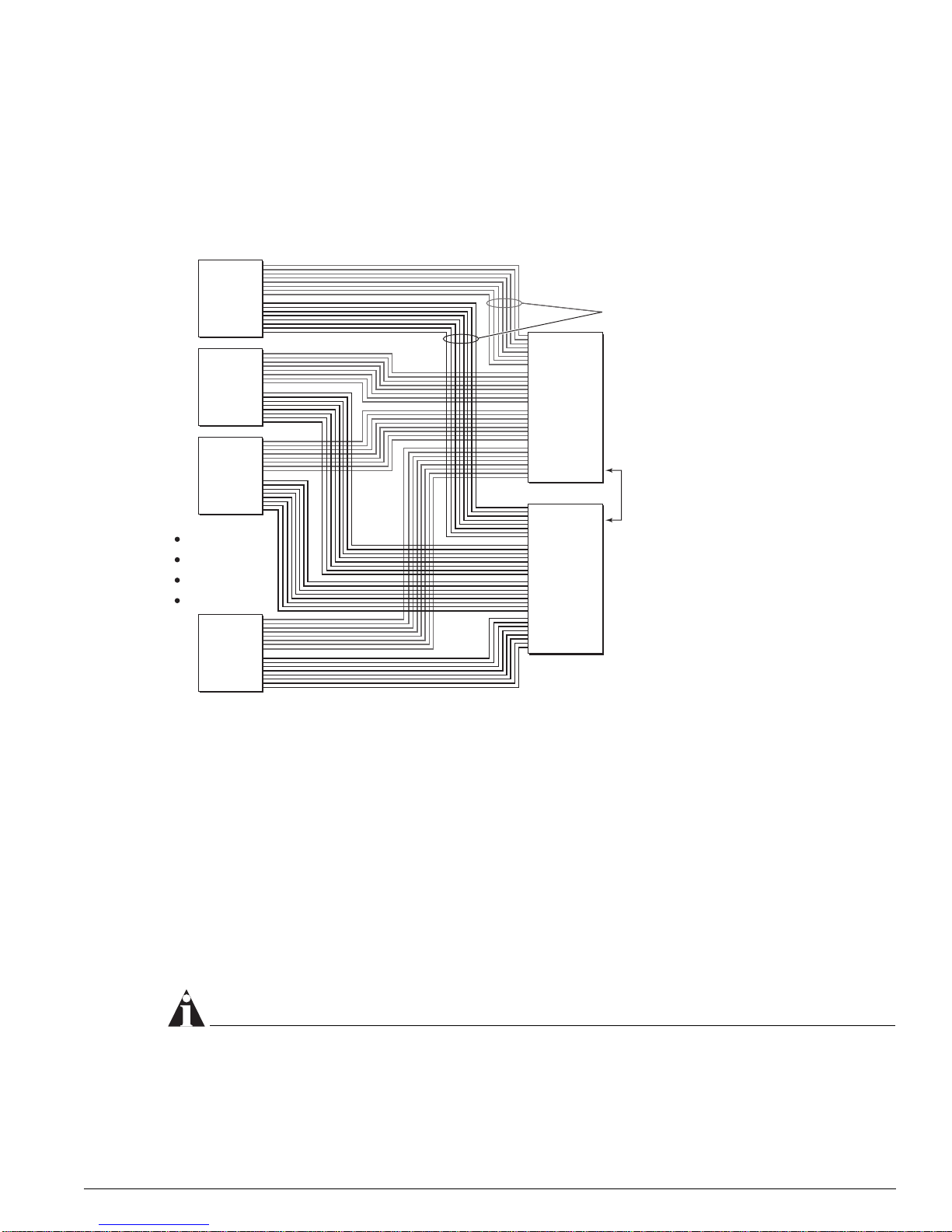
Figure 2: BlackDiamond passive backplane architectur e (BlackDiamond 6808 shown)
Switch
1
Module
Switch
2
Module
64 Gbps
Switch
Fabric
Eight Load-Shared
Gigabit Links
Switch
3
Module
64 Gbps
Switch
Fabric
Switch
8
Module
A
Fault-Tolerant
Switch Fabric
and System
Management
B
DN_001
The BlackDiamond backplane provides inter-slot electrical connections for both network data traffic and
a separate control bus for switch fabric management. Data traffic is carried on four AUI links between
each MSM and each I/O slot on BlackDiamond
links between each MSM and each I/O slot on BlackDiamond
6804 and BlackDiamond 6808 systems, and on two AUI
6816 systems. Device management occurs
on a 32-bit PCI bus connecting MSMs and I/O modules. The number of backplane slots for I/O
modules and MSMs determines the BlackDiamond system type (6804, 6808, 6816).
The chief advantages of a passive backplane are:
• The absence of active components yields a much lower possibility of backplane failure.
• You can remove and replace system modules faster, making upgrades and repairs easier, faster, and
cheaper.
NOTE
One disadvantage of a passive backplane is th at a problem on one switch module might cause other
switch modules to fail. More infor mation on this possibility is c overed in later chapters of t his guide.
Advanced System Diagnos tics and Troubleshooting Guide 17
“i” Series Switch Hardware Architecture
BlackDiamond I/O Modules
Each BlackDiamond I/O module has a built-in switching fabric (see Figure 3) giving the module the
capability to switch local traffic on the same module. Traffic that is destined for other modules in the
chassis travels across the backplane to the MSMs, where it is switched and sent to its destination I/O
module.
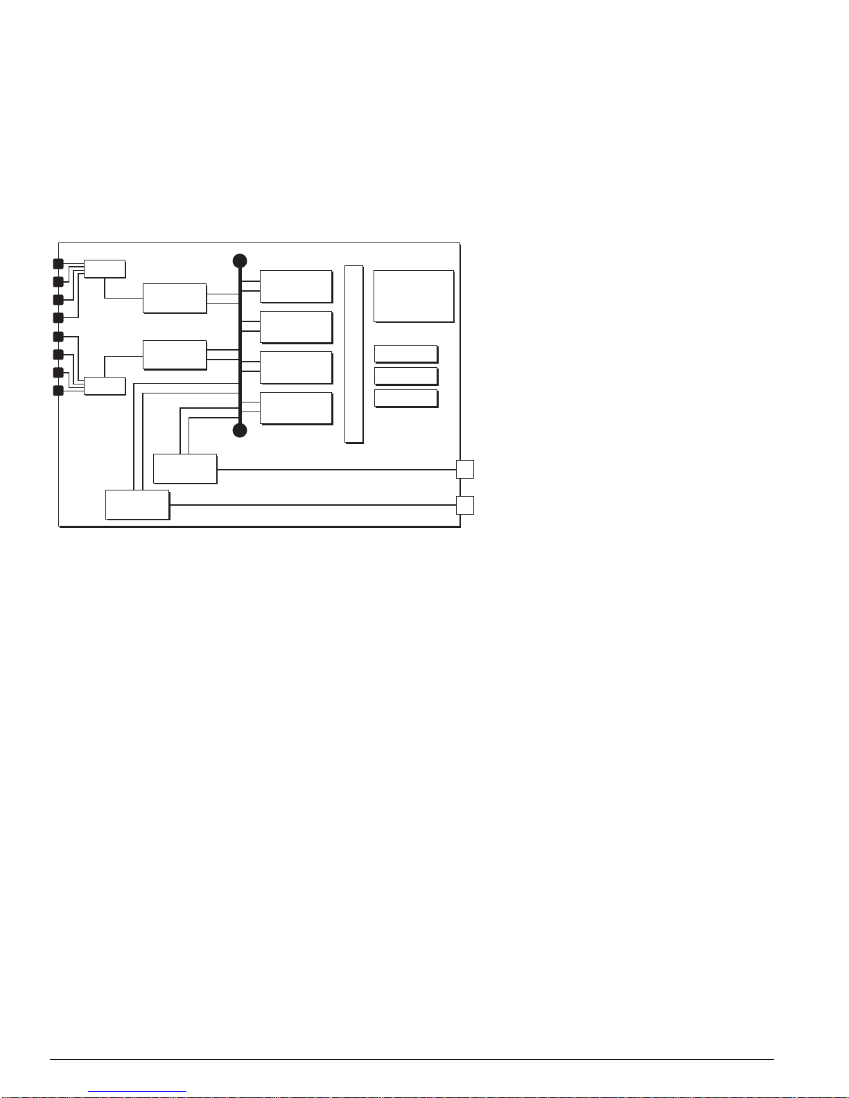
Figure 3: BlackDiamond I/O module archit ecture (G8Xi 32 Gb fabric s hown)
PHY
MAC
MAC
PHY
PBUS
MAC
MAC
SE
ASIC
SE
ASIC
SE
ASIC
SE
ASIC
SRAM (Packet Mem + FDB)
AFQM
ASIC
OTP RAM
PQ RAM
VPST RAM
4x GbE to
MSM-A
4x GbE to
MSM-B
DN_026C
Each BlackDiamond I/O module has eight load-shared Gigabit Ethernet links to both MSMs through
the backplane. The load sharing algorithm distributes traffic across different channels through the
backplane’s Gigabit Ethernet links, providing bi-directional communication.
Each BlackDiamond I/O module is equipped with the following kinds of hardware components:
• PHY: An industry-standard ASIC responsible for physical layer (layer 1) signal, clocking, etc.
• MAC: The MAC handles the standard MAC layer functions as well as some other functions to
prepare a packet for transmission to the switch fabric or to the external network, including 802.1p
and DiffServ examination, VLAN insertion, MAC substitution, TTL decrement, 802.1p and DiffServ
replacement, etc.
Each I/O module has both external MACs and internal MACs. External MACs handle the interface to
the external ports; internal MACs handle the interface to the BlackDiamond backplane. Each MSM
provides four Gigabit Ethernet links to each I/O module.
• PBUS: The packet data bus that transfers packets between the MAC and the packet memory.
• Switch engine (distributed packet processor) ASIC (Twister) and its associated memories: packet
RAM and FDB RAM. The SE ASIC implements a high-speed, parallel data transfer bus for
transferring packets from MACs to packet memory and back.
• Address filtering and queue management ASIC (Quake) and its associated memories: OTP RAM, PQ
RAM, and VPST RAM.
When a data packet is received by the PHY, the PHY passes the packet to the MAC. The MAC handles
the layer
18 Advanced System Diagnostics and Troubleshooting Guide
2 tasks, such as tagging and the MAC address, then transfers the packet across the PBUS to the
The BlackDiamond Sy stems
packet memory for temporary storage. Based on the information in memory, such as the FDB, the
address filtering and queue management ASIC makes a forwarding decision. If the next hop is a local
port (on the same module), the packet is forwarded to the external MAC and PHY for the exit port. If
the packet is destined for another module (as either slow path traffic or fast path traffic), the packet is
transferred to the internal MAC and then on to the MSM (CPU).
All I/O modules share the management bus on the backplane, and use it to communicate to each other
and to the MSMs.
Management Switch Modules
As its name indicates, the Management Switch Fabric Module (MSM) serves a dual role in the system: it
is equipped to act as the internal switch fabric for data that is being transferred between I/O modules
in the chassis, and to handle the upper-layer processing and system management functions for the
switch. (See
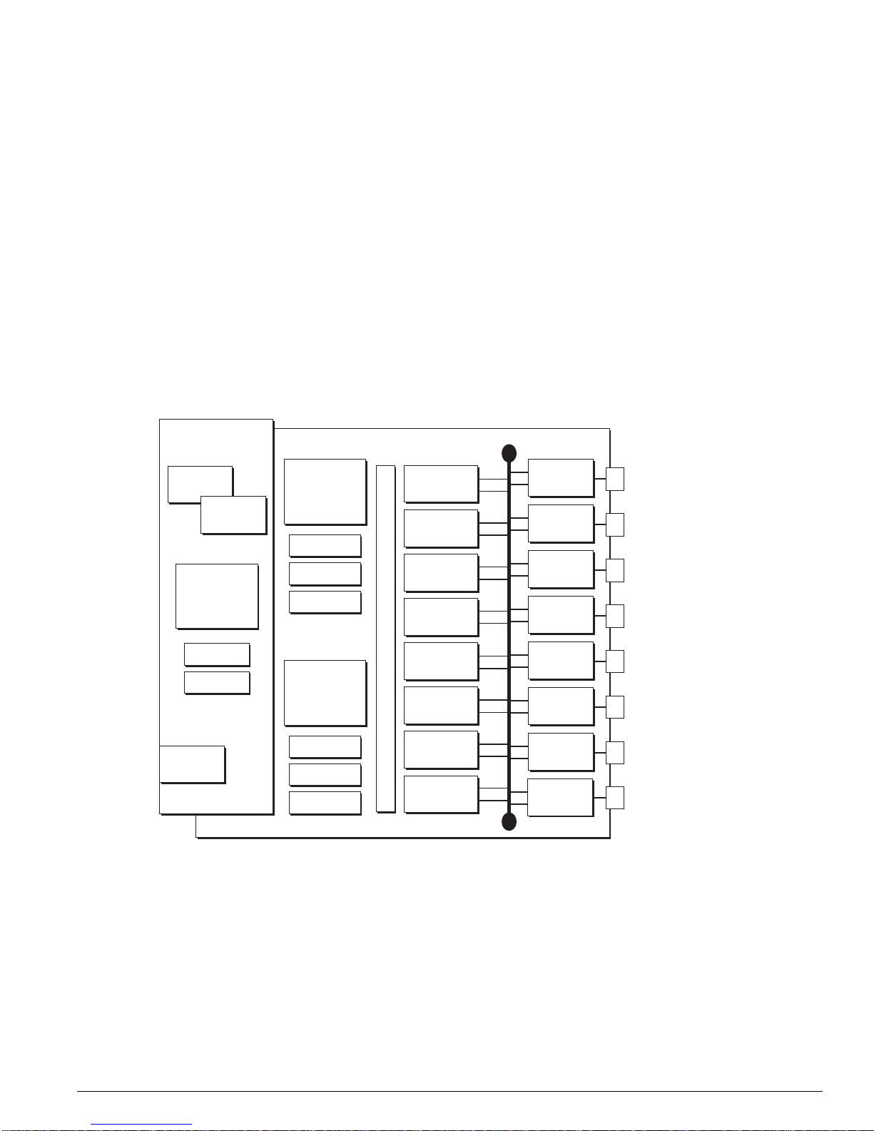
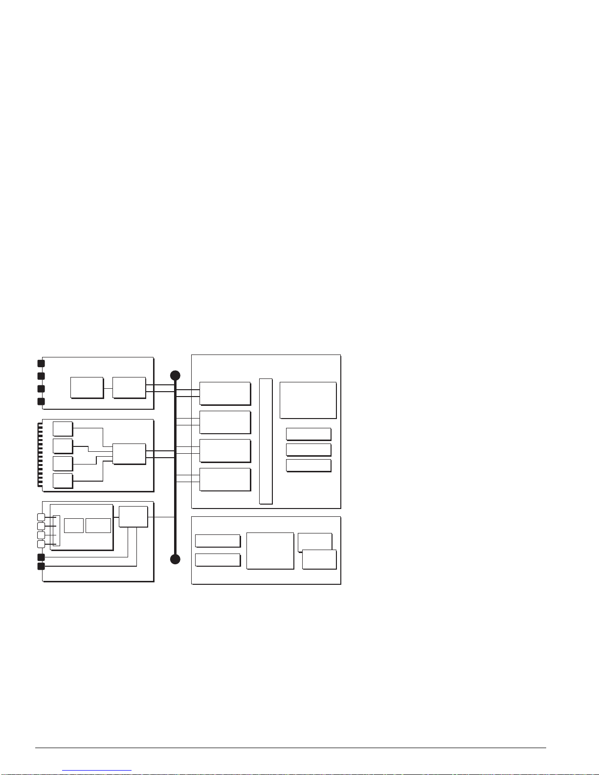
Figure 4: BlackDiamond MSM architecture ( MSM64i shown)
Subsystem
Figure 4.)
CPU
CPU
256 MB
NVRAM
PCMCI
Slot
CPU
DRAM
Flash
AFQM
ASIC
OTP RAM
PQ RAM
VPST RAM
AFQM
ASIC
OTP RAM
PQ RAM
VPST RAM
SE
ASIC
SE
ASIC
SRAM (Packet Mem + FDB)
SE
ASIC
SE
ASIC
SE
ASIC
SE
ASIC
SE
ASIC
SE
ASIC
PBUS
MAC
MAC
MAC
MAC
MAC
MAC
MAC
MAC
DN_027C
An MSM is equipped with the following hardware components: CPU subsystem (dual CPUs, DRAM,
NVRAM, flash memory, and PCMCIA slot) and switch fabric subsystem (Quake ASICs, OTP, PQ, and
VPST RAM, packet memory and FDB SRAM, Twister ASICs, PBUS, and MAC ASICs).
Advanced System Diagnos tics and Troubleshooting Guide 19
“i” Series Switch Hardware Architecture
BlackDiamond MSM Redundancy
The CPU subsystems on a pair of BlackDiamond MSMs operate in a master-slave relationship.
(See
Figure 5.)
Figure 5: BlackDiamond MSM redundancy s cheme
Fault Tolerant
Switch Fabric
and
System
Management
MSM64i (A)
CPU
Sub-
system
MSM64i (B)
CPU
Sub-
system
CPU Control Path
Data Path
Switching
Fabric
Switching
Fabric
Backplane
I/O Module
I/O Module
I/O Module
I/O Module
I/O Module
I/O Module
I/O Module
I/O Module
DN_028A
The master MSM CPU subsystem actively manages the switch and the task of switching packets in the
CPU control (or management) path. The slave MSM CPU subsystem is in standby mode, but is checked
periodically by the master MSM CPU (via EDP) to determine whether it is still available.
The master MSM also guarantees that management operations occur in a synchronized manner. For
example, if you make a configuration change and need to save it, the master MSM ensures that the
configuration is saved to both the master MSM and the slave MSM at the same time. That way, the
updated slave is ready to take over as the master if the master MSM fails.
Despite the master-slave switch management role, the switch fabrics on both MSMs actively switch core
traffic in a load-shared fashion. Load-sharing switches core traffic from different I/O modules.
All MSMs share the control (or management) bus on the backplane, and use it to communicate to each
other and to installed I/O modules to perform system health checks and status polling.
Causes of MSM Failover and System Behavior
A number of events can cause an MSM failover to occur, including:
• Software exception; system watchdog timer expiry
• Diagnostic failure (extended diagnostics, transceiver check/scan, FDB scan failure/remap)
• Hot removal of the master MSM or hard-reset of the master MSM
20 Advanced System Diagnostics and Troubleshooting Guide

The BlackDiamond Sy stems
The MSM failover behavior depends on the following factors:
• Platform type and equippage (Summit vs. Alpine vs. BlackDiamond)
• Software configuration settings for the software exception handling options such as system
watchdog, system recovery level, and reboot loop protection. (For more information on the
configuration settings, see
Chapter 4, “Software Exception Handling.”)
In normal operation, the master MSM continuously resets the watchdog timer. If the watchdog timer
expires, the slave MSM will either 1) reboot the chassis and take over as the master MSM (when the
switch is equipped with MSM-64i modules), or 2) initiate a hitless failover (when the switch is
equipped with MSM-3 modules). The watchdog is a software watchdog timer that can be enabled or
disabled through CLI commands. The watchdog timer is reset as long as ExtremeWare is functioning
well enough to return to the main software exception handling loop where the critical software
exception handling tasks, such as tBGTask, handle the process of resetting the watchdog timer and
creating log entries.
• Software configuration settings for the system health check feature, or for any of the diagnostic tests
that you might choose to run manually.
For example, in the context of memory scanning and mapping, Chapter 5, “Diagnostics,” contains
three tables that describe the behavior of the switch for different platform types and diagnostics
configuration:
— Ta bl e 6: Auto-recovery memory scanning and memory mapping behavior
— Ta bl e 7: Manual diagnostics memory scanning and memory mapping behavior, normal
— Ta bl e 8: Manual diagnostics memory scanning and memory mapping behavior, extended
NOTE
On switches equipped with MSM 64i modules, you should per iodically use the
synchronize
command
to ensure that the slave MSM and mast er MSM are using matched images and configuration s. If not
synchronized, the slave MSM might attem pt to use the image it has l oaded in conjunction wi th the
configuration from the ma ster MSM, a mismatch t hat will most likely caus e the switch to behave
differently after an MSM failover, thereby defeating the intended purpose of red undant peer MSMs.
If you need to insert a new MSM, you can duplicate the contents of the NVRAM and flash memory
from an existing MSM to the newly-installed MSM using one CLI synchronization command.
NOTE
The MSM-3 uses technol ogy that provides “hitless” failover, meaning the MSM-3 transitions through a
failover with no traffic loss and no switch downtime, while it maintains ac tive links and preserves layer
state tables. Contrast this performance to normal failover with MSM64i modules, which can take the
switch down for approximately 30
seconds. The MSM-3 makes hitless upgrade s possible. It is suppor ted
in ExtremeWare release 7.1.1 and l ater.
2
Advanced System Diagnos tics and Troubleshooting Guide 21
“i” Series Switch Hardware Architecture
Alpine Systems
Like the BlackDiamond systems, the Alpine systems are also based on a multislot modular chassis that
uses the inferno chipset, but the Alpine switches differ from the BlackDiamond switches on these points
(see
Figure 6):
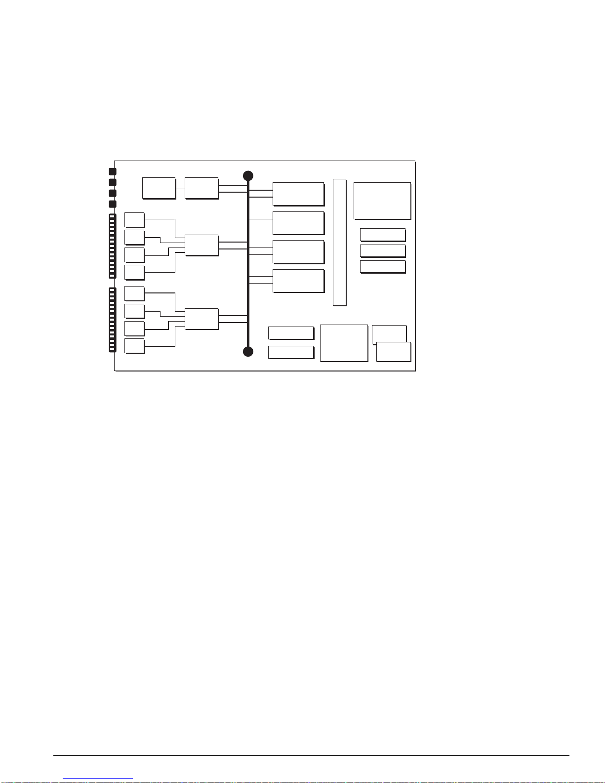
• Active backplane—Alpine switches use an active backplane that uses the same basic set of ASICs
(the switch engine ASIC and the address filtering and queue management ASIC) and memory
(packet memory for storing packets; OTP RAM, PQ RAM, and VPST RAM) that are used on the
BlackDiamond MSMs and I/O modules, so it offers wire-speed switching.
But unlike the BlackDiamond MSM, the Alpine backplane has no CPU and no MAC. It does provide
PBUS links to all I/O modules. The number of backplane slots for I/O modules determines the
Alpine system type (3802, 3804, 3808).
• SMMi processor module instead on MSM—The SMMi processor module is similar to the CPU
subsystem of the BlackDiamond MSM in that it is equipped with the following hardware
components: CPU subsystem, DRAM, NVRAM, and flash memory, console port connectors,
management interface, and a PCMCIA slot. But unlike the MSM, the SMMi contains no switching
fabric.
• I/O modules provide PHY and MAC functionality, but no onboard switching fabric—Each
standard I/O module has two PBUS links to the switching fabric on the Alpine backplane.
Figure 6: Alpine architecture (Alpi ne 3804 shown)
PHY
PHY
PHY
PHY
WAN Subsystem
CPU DRAM
2x 10/100base-TX
GM-4Xi
MACPHY
FM-32Ti
MAC
MAC
WM-4T1
PBUS
Alpine 3804 (32 Gb Fabric)
SE
ASIC
SE
ASIC
SE
ASIC
SE
ASIC
CPU Subsystem
Flash
NVRAM
SMMi
SRAM (Packet Mem + FDB)
256 MB
DRAM
AFQM
ASIC
OTP RAM
PQ RAM
VPST RAM
CPU
CPU
DN_029C
22 Advanced System Diagnostics and Troubleshooting Guide
Summit “i” Series Sy stems
Summit “i” Series Systems
Unlike the BlackDiamond and Alpine systems, the Summit “i” series stackables are not modular
systems: all of the system components are integrated into one unit. (See
Figure 7: Summit “i” series architecture
Figure 7.)
PHY
PHY
PHY
PHY
PHY
PHY
PHY
PHY
MACPHY
MAC
MAC
PBUS
SE
ASIC
SE
ASIC
SE
ASIC
SE
ASIC
Flash
NVRAM
SRAM (Packet Mem + FDB)
256 MB
DRAM
AFQM
ASIC
OTP RAM
PQ RAM
VPST RAM
CPU
CPU
DN_030A
The Summit CPU subsystem is similar to the CPU subsystem of the BlackDiamond MSM and the
Alpine SMMi in that it is equipped with the same basic hardware components: dual CPUs, memory
(DRAM, NVRAM, and flash memory), console port connectors, management interface, and a PCMCIA
slot.
The Summit switching fabric subsystem uses the same basic set of ASICs (the switch engine ASIC and
the address filtering and queue management ASIC) and memory (packet memory for storing packets;
OTP RAM, PQ RAM, and VPST RAM) that are used on the BlackDiamond and Alpine switches, so it,
too, offers wire-speed switching.
The Summit I/O subsystem provides PHY and MAC functionality in a variety of port configurations
(types of ports and numbers of ports).
Advanced System Diagnos tics and Troubleshooting Guide 23

“i” Series Switch Hardware Architecture
24 Advanced System Diagnostics and Troubleshooting Guide

3 Packet Errors and Packet Error
Detection
This chapter describes some of the factors that might result in packet errors in the switch fabric and the
kinds of protection mechanisms that are applied to ensure that packet error events are minimized and
handled appropriately.
This chapter contains the following sections:
• Overview on page 25
• Definition of Terms on page 26
• Standard Ethernet Detection for Packet Errors on the Wire on page 27
• Extreme Networks’ Complementary Detection of Packet Errors Between Wires on page 27
• Failure Modes on page 30
• Health Check Messages on page 33
Overview
Complex, wire-speed switch fabrics are subject to electronic anomalies that might result in packet errors.
The Ethernet standard contains built-in protections to detect packet errors on the link between devices,
but these mechanisms cannot always detect packet errors occurring in the switch fabric of a device.
Extreme Networks has incorporated many protection mechanisms to ensure that packet error events are
minimized and handled properly.
These protection mechanisms include the following:
• Ethernet CRC (detects packet errors between switches)
• Switch fabric checksums (automatic detection of live packet errors)
• Packet memory scanning (offline detection of packet memory errors)
• System health check (automatic test of various CPU and data paths)
• FDB scan (background scan process scans entire FDB RAM pool on all switch fabrics)
• Transceiver check (background detects packet errors on internal control paths)
Advanced System Diagnos tics and Troubleshooting Guide 25

Packet Erro rs a nd Packe t Err or D ete ctio n
Definition of Terms
To establish a basis for the descriptions in this chapter, Ta bl e 3 lists and defines terms that are used
repeatedly throughout this chapter and those that follow. When any of these terms are used for their
precise meaning, they are shown emphasized in bold type.
Table 3: Data E rror Ter ms
Term Description
Packet error event When the contents of a network data or control packet are modified by the
Checksum A value computed by running actual packet data through a polynomial formula.
Packet checks um A checksum value that is computed by the MAC chip when the packet is transferred
Verification checksum A checksum value that is computed by the MAC chip when the packet is transferred
Checksum error When a packet exits the switch fabric, the packet checksum that follows the packet
System healt h check A series of system tests and associated reporting mechanisms that are used to notify
System heal th check er ror This term refers to error messages in the system log that are generated by the
Transient errors Errors that occur as one-time events during normal system processing. These types
Soft-state errors These types of error events are characterized by a prolonged period of reported
Permanent errors These types of errors result from permanent hardware defects that might, or might
transmission medium or a network device in a way that is not indicated by the rules
of standard network behavior such that the contents of the packet will be considered
invalid by upper layer protocols or applications, we say that a packet
has occurred.
Note that the term applies only to packet changes initiated by layer 1 interaction; that
is, if an error in the electrical or optical processing of the bit-level data in the packet
results in a change to the packet, we consider this a packet
The term does not extend to systematic software or hardware errors that result in
valid but incorrect changes to the packet at higher OSI layers, such as inserting the
wrong next-hop MAC destination address into the packet header because of an
erroneous entry in the hardware forwarding database.
Checksums are one of the tools used by Extreme Networks in attempts to detect
and manage packet
from the MAC chip to the switch fabric. This checksum value precedes the packet
as it transits the switch fabric.
from the switch fabric to the MAC chip for transmission.
must match the verification checksum computed as the packet leaves the switch
fabric. If the checksums do not match, then a checksum error results.
network operators of potential system problems and to isolate and diagnose faulty
components when problems occur. The checksum error reporting mechanism is a
part of the system health check system.
system health check system. Error messages generated by the system health
check system are prefaced by the text string “Sys-health-check.” Checksum error
messages are a subset of the system health check error messages.
of errors will occur as single events, or might recur for short durations, but do not
have a noticeable impact on network functionality and require no user intervention to
correct.
error messages and might, or might not, be accompanied by noticeable degradation
of network service. These events require user intervention to correct, but are
resolved without replacing hardware.
Error messages of this type are the result of software or hardware systems entering
an abnormal operating state in which normal switch operation might, or might not, be
impaired.
not, affect normal switch operation. They cannot be resolved by user intervention
and will not resolve themselves. You must replace hardware to resolve permanent
errors.
error events.
error event.
error event
26 Advanced System Diagnostics and Troubleshooting Guide

Standard Ether net Detectio n for Packet Errors on the Wire
Table 3: Data Error Terms (continued)
Term Description
Fast path This term refers to the data path for a packet that traverses a switch and does not
Slow path This term refers to the data path for packets that must be processed by the switch
require processing by the CPU. Fast path packets are handled entirely by ASICs
and are forwarded at wire rate.
CPU, whether they are generated by the CPU, removed from the network by the
CPU, or simply forwarded by the CPU.
Standard Ethernet Detection for Packet Errors on
Wire
the
Data transiting from one switch to another is checked for packet errors using the Ethernet Cyclic
Redundancy Check (CRC) built into the IEEE 802.3 specification.
As the sending switch assembles a frame, it performs a CRC calculation on the bits in that frame and
stores the results of that calculation in the frame check sequence field of the frame. At the receiving end,
the switch performs an identical CRC calculation and compares the result to the value stored in the
frame check sequence field of the frame. If the two values do not match, the receiving switch assumes
that packet data has been illegally modified between CRC calculation and CRC validation and discards
the packet, and increments the CRC error counter in the MAC device associated with that port. In
Extreme Networks devices, ExtremeWare polls the MAC CRC error count registers and makes that
information available through the output of the
show port rxerrors CLI command.
Extreme Networks’ Comp lementary Detection of Packet
Errors Between Wires
The 802.3 Ethernet specification provides a CRC check for validation of data on the wire, but offers no
guidance for handling data validation in the devices between the wires. Because these devices are far
more complicated than the wires connected to them, common sense indicates the requirement for some
mechanism for checking internal data integrity. To complement the Ethernet CRC data validation
scheme, Extreme Networks switches implement an internal data checksum validation scheme referred
to as the fabric checksum.
The switch fabric in a switch is essentially an extremely high-speed data path connecting multiple ports
and using a set of programmable lookup tables to make intelligent forwarding decisions when moving
data from point to point inside the switch.
illustrate data movement within a switch.
Figure 8 uses a generalized block diagram of a switch to
Advanced System Diagnos tics and Troubleshooting Guide 27
Packet Erro rs a nd Packe t Err or D ete ctio n
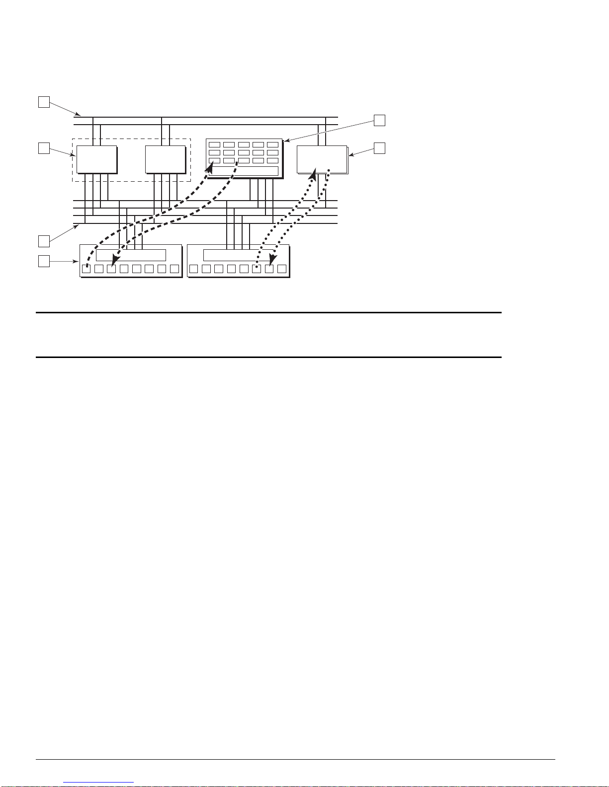
Figure 8: Generalized switch block diagram
4
5
3 6
ASICASIC
DMAC
2
1
1 PHY port and MAC device layer 4 Control bus
2 Packet bus (PBUS) 5 P acket memory
3 Forwarding ASICs 6 CPU subsystem
MAC MAC
CPU
sub-system
CG_002B
The following sections describe the hardware and software components that work together to detect
and manage packet error incidents within the Extreme Networks switch.
Hardware System Detection Mechanisms
All Extreme Networks switches based on the “i”-series switch fabric validate data integrity internal to
the switch fabric using a common checksum verification algorithm. Using
Figure 8 as a generalized
model, when a packet is received at an Ethernet network interface, the receiving MAC ASIC verifies the
Ethernet CRC: it computes a CRC value by applying the same algorithm used to compute the CRC
value appended to the received packet data by the transmitting switch. If the algorithm and the data it
is applied to are the same on both ends of the Ethernet link, the CRC values should match. If they do
not, the packet is assumed to have been damaged and is discarded.
If the CRC values match, the MAC ASIC must then transfer the packet to the internal switch fabric.
Before doing this, however, it produces a checksum value based on the packet data being passed to the
switch fabric. This checksum value becomes the packet checksum. It is prepended to the packet and
both the packet checksum and packet are passed on to the switch fabric.
After the switch fabric is finished processing the packet and has made a decision regarding where the
packet is to be forwarded, it passes the packet to the transmitting MAC ASIC. The transmitting MAC
ASIC performs the reverse of the process performed by the receiving MAC ASIC. It first computes a
checksum value based on the packet data received from the switch fabric. We will call this value the
verification checksum.
The transmitting MAC ASIC then compares the verification checksum against the packet checksum. If
the two values do not match, the result is a checksum error. The MAC ASIC maintains a count of every
checksum error that occurs on every port. When a packet is found to have a checksum error, it is still
28 Advanced System Diagnostics and Troubleshooting Guide

Extreme Networks’ Co mplement ary Detec tion of Packet Errors Between W ires
transmitted, but an invalid CRC value is included with the packet. Therefore, the receiving device will
detect an invalid CRC value and will drop the packet.
In Summit “i” series stackable switches, the packet checksum is calculated by the MAC ASIC on the
receiving port and is compared against the verification checksum calculated by the MAC ASIC on the
transmitting port, as described above.
In Alpine 3800 series switches, the packet checksum is calculated by the MAC ASIC on the receiving
port on the I/O module on which the packet is received. The packet checksum and packet are passed to
the switch fabric, which is on the Alpine switch backplane, and then from the switch fabric to the
transmitting MAC ASIC on the I/O module on which the packet is to be transmitted. There, the
verification checksum is computed and compared against the packet checksum.
In BlackDiamond 6800 series switches, the packet checksum is computed by the MAC ASIC on the
receiving port on the I/O module on which the packet is received. The packet checksum and the packet
traverse the switch fabric on the I/O module and are handed off to either an external MAC ASIC,
connected to a network port, or to an internal MAC ASIC, connected to a BlackDiamond backplane link.
In either case, the behavior of the MAC ASIC is the same: it computes the verification checksum and
compares it against the packet checksum to detect any changes in packet data. Similarly, whether the
packet is transmitted out the external port to the network, or out the internal port to the BlackDiamond
backplane, the packet is accompanied by an Ethernet CRC.
The behavior of the BlackDiamond MSM module is identical to that of the BlackDiamond I/O module,
except that all MAC ASICs on the MSM are internal (not to network ports). Regardless, the behavior of
the receiving and transmitting MAC ASICs is the same for packets traversing an MSM module as for
packets traversing an I/O module.
Thus far, all of the systems described have been involved in fast-path forwarding. Therefore, any
checksum errors detected using the mechanisms described above are referred to as fast-path checksum
errors.
Packets that must be processed by the switch CPU are also validated by checksum values. When a
packet is received, it might be destined specifically for the CPU (as in the case of protocol packets) or it
might be passed to the CPU for assistance in making a forwarding decision (if the switch fabric lacks
the information required to forward the packet correctly). In either case, the receiving MAC ASIC still
computes and prepends a packet checksum just as it does for fast-path packets, but because the packet
is not passed to a transmitting MAC ASIC before it is forwarded, the switch fabric itself is responsible
for computing the verification checksum and comparing it against the packet checksum. If a mismatch
is found, the switch fabric reports the checksum error condition to the CPU as it passes the packet up to
the CPU. These types of checksum errors are one instance of a class of checksum errors known as
slow-path checksum errors.
Software System Detection Mechanisms
As described above, each MAC ASIC maintains a port-by-port count of every checksum error detected.
ExtremeWare contains mechanisms that can retrieve the checksum error counts from the MAC ASICs in
the switch and act on it. Current versions of ExtremeWare retrieve the checksum error counts from all
MAC ASICs in the switch at twenty-second intervals. The counts at the end of the twenty-second
interval are compared with the counts at the beginning of the twenty-second interval on a port-by-port
basis. If, for any given port, the count is found to be different, then ExtremeWare is said to have
detected a checksum error.
Depending on the ExtremeWare version, the configuration settings, the frequency and count of
checksum errors, and a variety of other factors, ExtremeWare will initiate one of several actions,
Advanced System Diagnos tics and Troubleshooting Guide 29

Packet Erro rs a nd Packe t Err or D ete ctio n
described in the section “System (CPU and Backplane) Health Check” on page 70. For example, the
system health check facility can be configured such that ExtremeWare will insert a message into the
system log that a checksum error has been detected.
Failure Modes
Although packet errors are extremely rare events, packet errors can occur anywhere along the data path,
along the control path, or while stored in packet memory. A checksum mismatch might occur due to a
fault occurring in any of the components between the ingress and egress points—including, but not
limited to, the packet memory (SRAM), ASICs, MAC, or bus transceiver components.
There are many causes and conditions that can lead to packet error events. These causes and conditions
can fall into one of these categories:
• Transient errors
• Systematic errors
— Soft-state errors
— Permanent errors
The failure modes that can result in the above categories are described in the sections that follow.
Transient Failures
Transient failures are errors that occur as one-time events during normal system processing. These types
of errors will occur as single events, or might recur for short durations. Because these transient events
usually occur randomly throughout the network, there is usually no single locus of packet errors. They
are temporary (do not persist), do not have a noticeable impact on network functionality, and require no
user intervention to correct: There is no need to swap a hardware module or other equipment.
Systematic Failures
Systematic errors are repeatable events: some hardware device or component is malfunctioning in such a
way that it persistently exhibits incorrect behavior. In the context of the ExtremeWare Advanced System
Diagnostics, the appearance of a checksum error message in the system log—for example—indicates
that the normal error detection mechanisms in the switch have detected that the data in a packet has
been modified inappropriately. While checksums provide a strong check of data integrity, they must be
qualified according to their risk to the system and by what you can do to resolve the problem.
Systematic errors can be subdivided into two subgroups:
• Soft-state failures
• Permanent, or hard failures
Soft-State Fail ures
These types of error events are characterized by a prolonged period of reported error messages and
might, or might not, be accompanied by noticeable degradation of network service. These events require
user intervention to correct, but are resolved without replacing hardware.
30 Advanced System Diagnostics and Troubleshooting Guide
 Loading...