

Extreme Networks ExtremeWare 7.2e Installation And User Manual

Extreme Networks, Inc.
3585 Monroe Street
Santa Clara, California 95051
(888) 257-3000
http://www.extremenetworks.com
ExtremeW are 7.2e Installation
and User Guide
Software Vers ion 7.2e
Published: June 11, 2004
Part number: 100 157-00 Rev 0 3

2
Alpine, Altitude, BlackDiamond, EPICenter, Ethernet Everywhere, Extreme Ethernet Everywhere, Extreme Networks,
Extreme Turbodrive, Extreme Velocity, ExtremeWare, ExtremeWorks, GlobalPx Content Director, the Go Purple Extreme
Solution Partners Logo, ServiceWatch, Summit, the Summit7i Logo, and the Color Purple, among others, are trademarks
or registered trademarks of Extreme Networks, Inc. or its subsidiaries in the United States and other countries. Other
names and marks may be the property of their respective owners.
© 2004 Extreme Networks, Inc. All Rights Reserved.
Specifications are subject to change without notice.
Adobe and Reader are registered trademarks of Adobe Systems Incorporated. NetWare and Novell are registered
trademarks of Novell, Inc. Merit is a registered trademark of Merit Network, Inc. Solaris is a trademark of Sun
Microsystems, Inc. F5, BIG/ip, and 3DNS are registered trademarks of F5 Networks, Inc. see/IT is a trademark of F5
Networks, Inc.
“Data Fellows”, the triangle symbol, and Data Fellows product names and symbols/logos are
trademarks of Data Fellows.
F-Secure SSH is a registered trademark of Data Fellows.
A
uthors: Jeanine Healy, Richard Small
P
roduction: Jeanine Healy

ExtremeWare 7.2.0 Software User Guide 3
Contents
Introduction 15
Conventions 15
Related Publications 16
Using ExtremeWare Publications Online 17
Chapter 1 Summit 400-48t Switch Overview and Installation
Summary of Feature s 19
Hardware 19
Software 20
Summit 400-48t Switch Physical Features 21
Summit 400-48t Switch Front View 21
Summit 400-48t Switch Rear View 22
Summit 400-48t Switch LEDs 23
Mini-GBIC Type and Support 24
Mini-GBIC Type and Specifications 25
Port Connections 27
Uplink Redundancy 27
Software Overview 28
Virtual LANs (VLANs) 28
Spanning Tree Protocol 29
Quality of Service 29
Unicast Routing 29
IP Multicast Routing 29
Load Sharing 29
ESRP-Aware Switches 30
Software Licensing 30
Router Licensing 30
Security Licensing 31
Software Factory Defa ults 32

4 ExtremeWare 7.2.0 Software User Gui de
Contents
Switch Installation 33
Determining the Switch Location 33
Following Safety Information 33
Installing the Switch 34
Rack Mounting 34
Free-Standing 34
Desktop Mounting of M ultiple Switches 35
Installing or Replacing a Mini-Gigabit Interface Connector (Mini-GBIC) 35
Safety Information 35
Preparing to Install or Replac e a Mini-GBIC 35
Removing and Inserting a Mini-GBIC 36
Connecting Equipment to the Console Port 37
Powering On the Switch 38
Checking the Installation 38
Logging In fo r the First Time 39
Installing Optional Features 39
Installing the Summit X EN Card 40
Installing the External Po wer System 42
Rack Mounting the EPS-T 42
Adding a second EPS-160 to the EPS-T 45
Removing an EPS-160 from the EPS-T 45
Chapter 2 Managing the Switch
Overview 47
Using the Cons ole Interfac e 48
Using the 10/100/1000 Ethernet Management Port 48
Using Telnet 48
Connecting to Ano ther Host Using Telnet 49
Configuring Switch IP Parameters 49
Disconnecting a Telnet Session 51
Controlling Telnet Access 51
Using Secure Shell 2 (SSH2) 52
Using SNMP 52
Enabling and Disabling S NMPv1/v2c and SNMP v3 52
Accessing Switch Agents 53
Supported MIBs 53
Configuring SNMPv1/v2c Settings 53
Displaying SNMP Settings 54
SNMP Trap Groups 54
SNMPv3 56

ExtremeWare 7.2.0 Software User Guide 5
Contents
SNMPv3 Overview 57
Message Processing 57
SNMPv3 Security 58
MIB Access Control 60
Notification 61
Authenti cating U sers 63
RADIUS Client 64
TACACS+ 64
Configuring RADIUS Client and TACACS+ 64
Using Ne twork Lo gin 64
Using the Simple Network Time Protocol 64
Configuring and Using SNTP 65
SNTP Example 68
Chapter 3 Acce ssing the Swit ch
Understanding the Command Syntax 69
Syntax Helper 70
Command Shortcuts 70
Switch Numerical Ranges 71
Names 71
Symbols 71
Limits 72
Line-Editing Keys 72
Command History 72
Common Commands 72
Configuring Management Access 74
User Account 75
Administrator Account 75
Default Accounts 75
Creating a Management Account 76
Domain Name Service Client Services 77
Checking Basic Connectivity 78
Ping 78
Traceroute 78
Chapter 4 Configuring Ports
Enabling and Disabling Switch Ports 81
Configuring Switch Port Speed and Duplex Setting 81
Turning Off Autonegotiation for a Gigabit Ethernet Port 82
Configuring Link Detection 82
Configuring Interpacket Gap for Gigabit Ethernet Ports 82

6 ExtremeWare 7.2.0 Software User Gui de
Contents
Jumbo Frames 83
Enabling Jumbo Fram es 83
Jumbo Frames Example 84
Path MTU Discovery 84
IP Fragmentation with Jumbo Frames 84
IP Fragmentation with in a VLAN 85
Load Sharing on the Switch 85
Static Load Sharing 85
Load-Sharing Algorithm 86
Configuring Switch Load S haring 87
Load-Sharing Example 87
Veri fying the Load-Sharing Configuration 87
Switch Port-Mirroring 88
Summit 400 Switch Port-Mirroring Example 89
Extreme Discovery Protocol 89
Configuring Automatic Failover for Combination Ports 89
Automatic Failover Examples 90
Chapter 5 Virtual LANs (VLANs)
Overview of Virtual LANs 91
Benefits 91
Types of VLANs 92
Port-Based VLANs 92
Tagged VLANs 94
VLAN Names 96
Default VLAN 97
Renaming a VLAN 97
Configuring VLANs on t he Switch 97
VLAN Configuration Examples 98
Displaying VLAN Settings 98
MAC-Based VLANs 99
MAC-Based VLAN Guidelines 99
MAC-Based VLAN Limitations 100
MAC-Based VLAN Example 100
Timed Configuration Download for MAC-Based VLANs 100
Chapter 6 Forwarding Database (FDB)
Overview of the FDB 103
FDB Contents 1 03
How FDB Entries Get Added 103
FDB Entry Types 104
Disabling MAC Address Learning 105

ExtremeWare 7.2.0 Software User Guide 7
Contents
Associating QoS Profiles with an FDB Entry 105
FDB Confi guratio n Examp les 106
Displaying FDB Entries 107
Chapter 7 Quality of Service (QoS)
Overview of Po licy-Based Quality of Se rvice 110
Applications and Types of QoS 110
Voice Applications 110
Video Applications 110
Critical Database Applications 111
Web Browsing Applications 111
File Server Applications 111
Configuring QoS 112
QoS Profiles 112
Traffic Groupings 113
IP-Based Traffic Groupings 114
MAC-Based Traffic Groupings 114
Explicit Class of Service (802.1p a nd DiffServ) Traffic Groupings 115
Configuring DiffServ 117
Physical and Logical Groupings 119
Verifying Configuration and Performance 120
QoS Monitor 120
Displaying QoS Profile Informat ion 121
Modifying a QoS Configuration 121
Traffic Rate-Limiting 122
Chapter 8 Status Monitoring and Statistics
Port Statistics 123
Port Errors 124
Port Monitoring Display Keys 125
Setting the System Recovery Level 125
Event Management System/Logging 125
Sending Event Messag es to Log Targets 126
Filtering Events Sent to Targets 127
Formatting Event Messages 133
Displaying Real-Time Log Messages 134
Displaying Events Logs 134
Uploading Events Logs 135
Displaying Counts of Event Occurrences 135
Displaying Debug Informat ion 136

8 ExtremeWare 7.2.0 Software User Gui de
Contents
Compatibility with previous ExtremeWare commands 136
Logging Configuration Chan ges 137
RMON 138
About RMON 138
RMON Features of the Switch 138
Configuring RMON 139
Event Actions 140
Chapter 9 Security
Security Overview 141
Network Access Security 141
MAC-Based VLANs 142
IP Access Lists (ACLs) 142
Access Masks 142
Access Lists 142
Rate Limits 143
How Access Control Lists Work 144
Access Mask Precedence Numbers 145
Specifying a Default Rule 145
The permit-established Keyword 145
Adding Access Mask, Access List, and Rate Limit Entries 145
Deleting Access Mask, Access List, and Rate Limit Entries 146
Verify ing Access Control List Configu rations 146
Access Control List Examples 147
Network Login 150
Authentication Types 151
Modes of Oper ation 153
User Accounts 153
Interoperability Requirements 154
Multiple Supplicant Support 155
Exclusions and Limitations 156
Configuring Network Login 156
Web-Based Authentication User Login Using Campus Mode 157
DHCP Server on the Switch 159
Displaying DHCP Informati on 159
Displaying Network Login S ettings 159
Disabling Network Login 159
Additional Configuration Details 1 59
Switch Protection 160
Routing Access Profiles 160
Using Routing Access Profiles 161
Creating an Access Profile 161
Configuring an Access Profile Mode 161

ExtremeWare 7.2.0 Software User Guide 9
Contents
Adding an Access Profile Entry 162
Deleting an Access Profile Entry 163
Applying Access Profiles 164
Routing Profiles for RIP 164
Routing Access Profiles for OSPF 165
Routing Access Profiles for PIM 167
Denial of Service Protection 168
Configuring Denial of Service Protection 168
Creating Trusted Ports 169
Management Access Security 170
Authenticating Users Using RADIUS or TACACS+ 170
RADIUS Client 170
Configuring TACACS+ 176
Secure Shell 2 (SSH2) 177
Enabling SSH2 for Inbound Switch Access 177
Using SCP2 from an External SSH2 Clien t 178
SSH2 Client Functi ons on the Switch 179
Chapter 10 Ethernet Automatic Protection Switching
Overview of the EAPS Protocol 181
EAPS Terms 183
Fault Detection and Recovery 184
Link Down Message Sent by a Transit Node 185
Ring Port Down Event Sent by Hardware Layer 185
Polling 185
Restoration Operations 185
Configuring EAPS on a Switch 186
Creating and Deleting an EAPS Domain 186
Defining the EAPS Mode of the Switch 187
Configuring EAPS Polling Timers 187
Configuring the Primary and Secondary Ports 188
Configuring the EAPS Control VLAN 188
Configuring the EAPS Protected VLANs 189
Enabling and Disabling a n EAPS Domain 190
Enabling and Disabling E APS 190
Unconfiguring an E APS Ring Port 190
Displaying EAPS Stat us Information 190
Chapter 11 Spanning Tree Protocol ( STP)
Overview of the Spanning Tree Protocol 195
Spanning Tree Domains 196
STPD Modes 196

10 ExtremeWare 7.2.0 Software User Guid e
Contents
Port Modes 197
STPD BPDU Tunneling 197
Rapid Root Failover 198
STP Configurations 198
Basic STP Configuration 198
VLAN Spanning Mul tiple STPDs 200
EMISTP and PVST+ Deployment Constraints 201
Per-VLAN Spanning Tree 202
STPD VLAN Mapping 202
Native VLAN 202
Rapid Spanning Tree Protocol 202
RSTP Terms 203
RSTP Concep ts 203
RSTP Operation 206
STP Rules and Restrictions 213
Configuring STP on the Switch 213
STP Configuration Examples 214
Displaying STP Settings 216
Chapter 12 IP Unicas t Routing
Overview of IP Un icast Routing 219
Router Interfaces 220
Populating the Routing Table 221
Subnet-Directed Broadcast Forwarding 222
Proxy ARP 222
ARP-Incapable Devices 223
Proxy ARP Between Subnets 223
Relative Route Priorities 223
Configuring IP Unicast Routing 224
Verify ing the IP Unicast Routing Con figuration 225
Routing Configuration Example 225
ICMP Packet Processing 226
Configuring DHCP/BOOTP Relay 227
Configuring the DHCP Relay Agent Option (Option 8 2) 227
Verify ing the DHCP/BOOTP Rela y Configuration 228
UDP-Forwarding 229
Configuring UDP-Forwarding 229
UDP-Forwarding Example 229
UDP Echo Server 230
Chapter 13 Interior Gateway Protocols

ExtremeWare 7.2.0 Software User Guide 11
Contents
Overview 232
RIP Versus OSPF 232
Overview of RI P 233
Routing Table 233
Split Horizon 233
Poison Reverse 233
Tri ggered Updates 234
Route Advertisement of VLANs 234
R IP Ver si on 1 Ve rsus R IP Ver si on 2 2 34
Overview of OS PF 234
Link-State Database 235
Areas 236
Point-to-Point Support 2 39
Route Re-Distribution 240
Configuring Route Re-Distribution 240
RIP Configuration Example 242
Configuring OSPF 242
Configuring OSPF Wait Interval 242
OSPF Configuration Example 243
Configuration for ABR1 244
Configuration for IR1 244
Displaying OSPF Settings 245
OSPF LSDB Displa y 245
Authentication 245
Summarizing Level 1 IP Ro uting Information 246
Filtering Level 1 IP Routing In formation 246
Originating Default Route 246
Overload Bit 246
Default Routes to Nearest Level 1/2 Switch for Le vel 1 Only Switches 247
Chapter 14 IP Multicas t Routing
IP Multicast Routing Overview 249
PIM Sparse Mode (PIM-SM) Overview 250
Configuring PIM-SM 250
IGMP Overview 251
IGMP Snooping 252
Static IGMP 252
IGMP Snooping Filters 252
Multicast Tools 253
Mrinfo 253
Mtrace 253
Configuring IP Multicasting Routing 254

12 ExtremeWare 7.2.0 Software User Guid e
Contents
Configuration for IR1 254
Configuration for ABR1 255
Chapter 15 Using ExtremeWare Vista
on the Summit 400
ExtremeWare Vista Overview 257
Setting Up Your Browser 257
Accessing ExtremeWare Vista 258
Navigating within ExtremeWare Vista 260
Browser Controls 261
Status Messages 261
Configuring the Summit 400 using ExtremeWare Vista 261
IP Forwarding 262
License 263
OSPF 264
Ports 270
RIP 272
SNMP 275
Spanning Tree 277
Switch 281
User Accounts 281
Vi r tu a l L A N 2 8 2
Access List 284
Reviewing ExtremeWare Vista Statistic al Repor ts 287
Event Log 288
FDB 288
IP ARP 290
IP Configurati on 291
IP Route 293
IP Statistics 294
Ports 297
Port Collisions 2 98
Port Error s 299
Port Utilization 300
RIP 301
Switch 302
Locating Support Information 303
Help 303
TFTP Download 304
Logging Out of E xtremeWare Vista 307
Appendix A Technical Specifications
Summit 400-48t Switch 309

ExtremeWare 7.2.0 Software User Guide 13
Contents
Supported Protocols, MIBs, and Standards 311
Appendix B Software Upgrade and Boot Options
Downloading a New I mage 317
Selecting a P rimary or a Sec ondary Ima ge 317
Understanding the Image Version String 318
Software Signatures 319
Rebooting the Switch 319
Saving Configuration Changes 319
Returning to Factory Defaults 320
Using TFTP to Upload the Configuration 320
Using TFTP to Download the Configuration 321
Downloading a Complete Co nfiguration 321
Downloading an Incremental Configura tion 321
Scheduled Incremental Configuration Download 322
Remember to Save 322
Upgrading and Accessing BootROM 322
Upgrading BootROM 322
Accessing the BootROM Menu 322
Appendix C Troubleshooting
LEDs 325
Cable Diagnostics 326
Using the Command-Line Interface 327
Port Configuration 328
VLANs 329
STP 330
Debug Tracing/Debug Mode 330
TOP Command 331
System Odometer 331
Reboot Loop Protecti on 331
Minimal Mode 331
Contacting Extreme Technical Support 332

14 ExtremeWare 7.2.0 Software User Guid e
Contents

ExtremeWare 7.2e Installation and User Guide 15
Preface
This preface provides an overview of this guide, describes guide convent ions, and lists other
publications that might be useful.
Introduction
This guide provides the required information to in stall the Summit 400-4 8 switch and configure the
ExtremeWare
™
software running on the Summit 400-48 switch.
This guide is intended for use by net work administrators who a re responsible for installing and setting
up network equipment. It assu mes a basic working knowled ge of:
• Local area networks (LANs)
• Ethern et conc epts
• Ethernet switching and bridging concepts
• Routing concepts
• Internet Protocol (IP) conce pts
• Routing Information Protocol (RIP) and Open Shortest Path First (OSPF).
• IP Multicast concepts
• Protocol Independent Multicast (PIM) concepts
• Simple Network Management Protocol ( SNMP)
NOTE
If the information in the relea se notes ship ped with yo ur switch di ffers from the information i n this guide,
follow the release notes.
Conventions
Table 1 and Table 2 list conventions that are used throughout this guide.

16 ExtremeWare 7.2e I nstallation an d User Guid e
Preface
Related Publications
The publications related to this one are:
• ExtremeWare 7.2e Release Notes
• ExtremeWare 7.2e Command Reference Guide
Table 1: Notice Icons
Icon Notice Type Alerts you to...
Note Important features or instructions.
Caution Risk of personal injury, system damage, or loss of data.
Warning Risk of severe pe rsonal injury .
Table 2: Text C onventions
Convention Description
Screen displays This typeface indicates command syntax, or represents information as it appears on the
screen.
The words “enter”
and “type”
When you see the word “enter” in this guide, you must type something, and then press
the Return or Enter key. Do not press the Return or Enter key when an instruction
simply says “type.”
[Key] names Key names are written with brackets, such as [Return] or [Esc].
If you must press two or more keys simultaneously, the key names are linked with a
plus sign ( +). Exam ple:
Press [Ctrl]+[Alt]+[Del].
Words in italicized type Italics emphasize a point or denote new terms at the place where they are defined in
the text.

Related Publications
ExtremeWare 7.2e Installation and User Guide 17
Documentation for Extreme Networks products is av ailable on the World Wide Web at the following
location:
http://www.extremenetworks.com/
Using ExtremeWare Public ations Online
You can access ExtremeWare publications by downloading them from the Extreme Networks World
Wide Web location or from your ExtremeWare product CD. Publications are provided in Adobe
®
Portable Document Format (PDF). Displaying or printing PDF files requires that your computer be
equipped with Adobe
®
Reader® software, which is available free of charge from Adobe Systems
Incorporated.
The following two ExtremeWare publications are available as PDF fil es that are designed to be used
online together:
• ExtremeWare 7.2e Installation and User Guide
• ExtremeWare 7.2e Command Reference Guide
The user guide PDF file provides links that connect y ou directly to relevant command informa tion in
the command reference guide PDF file. This quick-referencing capability enab les you to easily find
detailed information in the comm and reference guide for any command mentioned in th e user guide.
To ensure that the quick-referencing feature functions properly, follow these steps:
1 Download both the user guide PDF file and the command reference guide PDF file to the same
destination directory on your com puter.
2 You may open one or both PDF files and to ena ble cross-referenced linking between the user guide
and command reference guide; however, it is recommended that for ease of use, you keep both files
open concurrently on your computer desktop.
NOTE
If you activate a cross-refer encing link from the ExtremeWar e 7.2e Installation and User G uide PDF file
to the command reference P DF file when the command reference PDF file is clo sed (that is, not
currently open on yo ur computer desktop ), the system will cl ose the user guide PDF file and open the
command reference P DF file. To keep both PDF fil es open when you activa te a cross-reference li nk,
open both PDF files befo re using the link.

18 ExtremeWare 7.2e I nstallation an d User Guid e
Preface

ExtremeWare 7.2e Installation and User Guide 19
1 Summit 400-48t Switch Overview and
Installation
This chapter describes the features and functionality of th e Summit 400-48t.
• Summary of Feat ures on page 19
• Summit 400-48t Switch P hysical Features on page 21
— Summit 400-48t Switch L EDs on page 23
— Mini-GBIC Ty pe and Support on page 24
— Port Connections on page 2 7
• Software Overview on page 28
— Software Licensing on page 30
— Software Factory Defaults on page 32
• Switch Installation on pa ge 33
— Determining the Switch Location o n page 33
— Following Safety Inform ation on page 3 3
— Installing the Switch on page 34
— Installing or Replacing a Mini-Gigabit Interface Conn ector (Mini-GBIC) on p age 35
— Connecting Equipment to the Console Port on page 37
— Powering On the Switch on page38
— Checking the Installation on page 38
— Logging In for the First Time on page 39
• Installing Optional Features on page 39
Summary of Features
Hardware
The Summit 400-48t supports the following ExtremeWare features:
• 48 copper ports 10/100/1000BASE-T
• 4 fiber SFP (mini-GBIC 1000BASE-SX, 1000BASE-LX, and 1000BASE-ZX)

20 ExtremeWare 7.2e I nstallation an d User Guid e
Summit 400-48t Switch Overview and In stallation
The fiber ports share PHY with the first four copper port.
• 1 copper management port 10/100/1000BASE-T
• 1 console port, serial
• 2 (optional) modular 10 Gigabit uplink ports
• 2 stacking ports (10 Gigabit) reserved for future software features
• Supports redundant power support using the optional EPS 16 0 External Powe r Supply
• Redundant uplink support
Software
The software features of the Summit 400-48t include:
• Virtual local area networks (VLANs) including support for IEEE 802.1Q and IEEE 802.1p
• VLAN aggregat ion
• Spanning Tree Protocol (STP) (IEEE 802.1D)
• Quality of Service (QoS) including support for IEEE 802.1P, MA C QoS, and eight hardware queues
• Policy-Based Quality of Service (PB- QoS)
• Wire-speed Internet Protocol (IP) routing
• Extreme Standby Ro uter Protocol (ESR P) - Aware support
• Ethernet Automated Protection Switching (EA PS) support
• Jumbo frame support
• DHCP/BOOTP Relay
• Routing Information Protocol ( RIP) version 1 and RIP version 2
• Open Shortest Path First (OSPF) routing protocol
• Wire-speed IP multicast routing support
• Diffserv supp ort
• Access-policy support for routing protocols
• Access list support for packet filtering
• Access list support for rate-limiting
• IGMP snooping to control IP multica st traffic
• Protocol Independent Multicast-Sparse Mode (PIM-SM)
• Load sharing on multiple ports
• RADIUS client and per-command authentication support
• TACACS+ support
• Console command line interface (CLI) connection
• Te l ne t CL I con n ec tio n
• SSH2 connection
• ExtremeWare Vista Web-based management interface
• Simple Network M anagement Protocol (SNM P) support
• Remote Monitoring (RMON)
Summit 400-48t Swi tch Physical F eatures
ExtremeWare 7.2e Installation and User Guide 21
• Traffic mirroring for ports by port number
• Network Login—Web
• Network Login—IEEE 802.1X
Summit 400-48t Switch Physical Featu res
The Summit 400-48t switch is a compact enclosure (see Figure 1) one rack unit in height (1 .73 inches or
44.0 mm) that provides 48 autosensing 10/100/1000BASE-T ports using RJ-45 connectors. The switch
also has four fiber ports that allow Gigabit Ethernet uplin k connections through Extreme 1000BASE-SX,
1000BASE-LX, or 1000BASE-ZX SFP mini-GBICs using LC connectors. The four fiber ports and the first
four of the 10/100/1000BASE-T ports are designed as shared, or combination ports for uplink
redundancy. When sharing ports, only the fiber port or on ly the copper port can be active at the same
time. For more information on cablin g and configuring this fea ture, see “Uplink Redundancy” o n
page 27.
Summit 400-48t Switch Front View
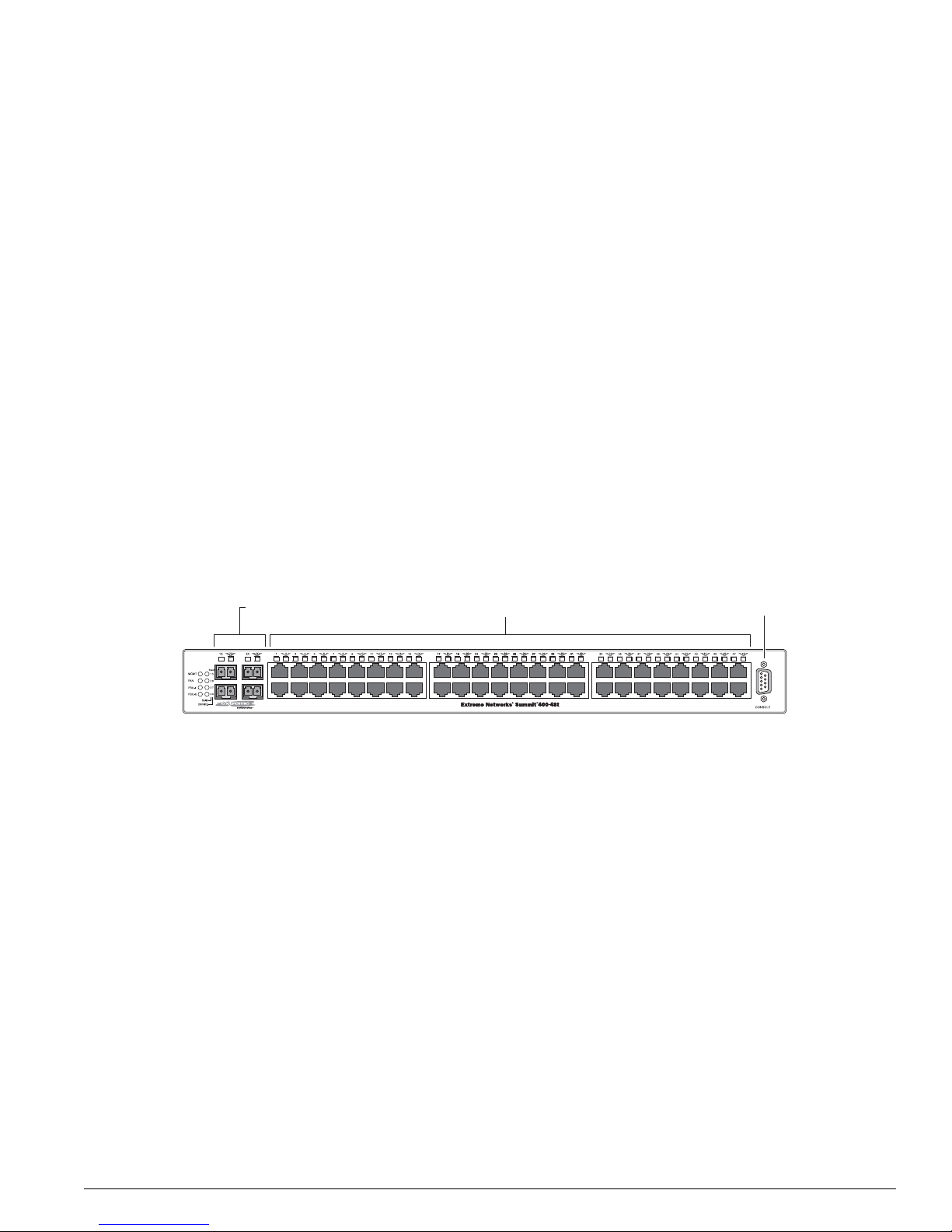
Figure 1 shows the Summit 400-48t switch front view.
Figure 1: Summit 400-48t switc h front view
The front panel consists of:
LEDs—For a description of the LEDs and their behavior, see “Summit 400-48t Switch LEDs” on page 23.
Fiber uplink ports—For more information about these four ports, see “Min i-GBIC Type and Support”
on page 24.
10/100/1000BASE-T ports—For more information about these 48 ports, see “Port C onnections” on
page 27.
Console Port—Use the console port (9-pin, “D” type connector) to attach a term inal and ac cess the CL I
through a serial connection. Use the console port to carry out local management.
ES4K001
10/100 Mbps ports
Console
port
Mini-GBIC ports

22 ExtremeWare 7.2e I nstallation an d User Guid e
Summit 400-48t Switch Overview and In stallation
Summit 400-48t Switch Rear View
Figure 2 shows the rear view of the Summ it 400-48t switch.
Figure 2: Summit 400-48t switch rear view
The rear panel consists of:
• An option slot for the dual 10 G igabit uplinks
To install this option, see “Instal ling Optional Feat ures” on page 39.
• The management port
The 10/100/1000BASE-T Ethernet management port communicates directly with the CPU of the
switch, bypassing the switch. Connect an Ethernet cable directly from a laptop into the management
port to view and locally manag e the switch configurations.
Do not assign an in-b and IP address to th e managem ent port VL AN. The ma nagement p ort VLAN is
an out-of-band VLAN, so if it is assigned an in-band IP address (an address where the source and
destination are in the same subnet), the switch treats it as a normal VLAN and attempts to route
traffic through it.
Extreme Networks does not recommend that you use the management po rt to route traffic to any
front panel port on the switch. The managem ent port is designed only for sw itch management
purposes.
There are two LEDs for the management port, located in the bottom corners of the port. The LED on
the bottom right turns solid green when a cable is inserted and the port detects a link. The LED on
the bottom left blinks green when there is transmission activity on the link.
• A compact flash slot
This slot is currently not supported but is reserved for future use.
• Two high-performance stacking ports
These ports are currently not supported but are reserved for future software features.
• Vents for the internal po wer supply fan.
• The connector for the optional Extreme External Power Supply System.
For further information abou t this feature, see “Installing Opti onal Features” on page 39.
• AC Power Socket
The Summit 400-48t switch automatically adjusts to the supply voltage. The power supply operates
from 100 VAC to 240 VAC.
ES4K018A
10 Gigabit
uplink option
Mgmt port
Compact flash
(reserved for future)
10 Gigabit stacking ports
(reserved for future)
Power socket
External power
supply connection

Summit 400-48t Switch LEDs
ExtremeWare 7.2e Installation and User Guide 23
NOTE
The Summit 400-48t sw itch certification , safety label, and ser ial number are loca ted on the bottom of
the switch.
Summit 400-48t Switch LEDs
The front panel displays five types of LEDs:
• Management
The MGMT LED indicates the status of the switch.
• Fan
The FAN LED indicates the statu s of the cooling fans.
• Power
The Summit 400-48t comes with an internal power supply and can be connected to the Extreme
External Power Supply tray. The status of the internal power supply is indica ted by the PSU-I LED.
The status of the external power supply is indicated by the PSU- E LED.
• 10/100/100 0BASE-T port stat us
Each of the 48 copper 10 /100/1000 BASE-T po rts has an associat ed LED locat ed above th e port.
• Fiber port status
Each of the four op tical fiber ports ha s an associated LED located above the port.
Table 3 describes the behavior of the front panel LEDs on t he Summit 400-48t switch.
Table 3: Su mmit 400-48t switch LED behavior
Unit Status LED (MGMT LED)
Color Indicates
Green, slow
blinking
Green, fast
blinking
Green, solid
Amber,
blinking
Off
The Summit switch is operating normally.
The Summit switch POST is in progress.
POST passed; ExtremeWare is booting.
The Summit switch has failed its POST or an overheat condition
is detected.
The Summit switch has no power.
Fan LED
Color Indicates
Green, solid
Amber,
blinking
Off
All fans are operati ng normal ly.
One or more fans has failed. The switch continues to operate
unless over-heating occurs.
The Summit switch has no power.

24 ExtremeWare 7.2e I nstallation an d User Guid e
Summit 400-48t Switch Overview and In stallation
Mini-GBIC Type and Support
The Summit 400-48t suppo rts the SFP GBIC, also k nown as the mini -GBIC, in three types: the SX
mini-GBIC, which conforms to the 1000BASE-SX standard, the LX mini-GBIC, which conforms to the
1000BASE-LX standard, and the ZX mini-GBIC, a long-haul mini-GBIC that conforms to the IEEE 802.3z
standard. The system uses identifier bits to determine the media type of th e mini-GBIC that is installed.
The Summit 400-48t supports only the SFP mini-GBIC.
NOTE
Only mini-GBICs that h ave been certified by Ex treme Networks (avail able from Extreme Networks )
should be inserted in to the mini-GBIC rece ptacles on the Summit 40 0-48t.
This section describes the mini-GBIC types and speci fications.
Power Supply LEDs
PSU-I Color Indicates
Green, solid
Amber,
blinking
Off
The internal power supply is operating normally.
The internal power supply has failed or the AC cord is not
connected. Check the cord connection. If the power supply has
failed, replace the internal power supply as soon as possible.
The internal power supply has no power.
PSU-E Color Indicates
Green, solid
Off
The external power supply is operating normally.
The external power supply is not connected.
Port Status LEDs (Ports 1–48)
Color Indicates
Green, solid
Green blinking
Off
The link is present; port is enabled.
The link is present and the port is transmitting or receiving
packets.
The link is not present.
Fiber LEDs (Ports 1X—4X)
Color Indicates
Green, solid
Green, blinking
Off
Fiber link is selected; mini-GBIC is present and being used for the
Gigabit Ethernet uplink.
The link is present and the port is transmitting or receiving
packets.
1000BASE-T link is selected; the switch is using the RJ-45 port
for the Gigabit Ethernet uplink.
Stack LEDs (Reserved for future features)
Table 3: Summit 400-48t switch LED behavior (Cont inued)

Mini-GBIC Type and Support
ExtremeWare 7.2e Installation and User Guide 25
Mini-GBIC Type and Specifications
Table 4 describes the mini-GBIC type and distances for the Summit 400-48t.
SX Mini-GBIC Specifications
Table 5 describes the specifications for the SX min i-GBIC.
Total optical system budget for the SX mini-GBIC is 11.5 dB. Extreme Networks recommends that 3 dB
of the total budget be reserved for losses induced by cable splices, connectors, and operating margin.
While 8.5 dB remains available for cable- induced attenuation, the 1000 BASE-SX standard specifies
supported distances of 275 meters ove r 62.5 micron multimod e fiber and 550 m eters over 50 micron
multimode fiber. There is no minimum attenua tion or minimum cable length restriction.
LX Mini-GBIC Specifications
Table 6 describes the specifications for the LX mini-GBIC.
Table 4: Mi ni-GBIC types and dis tances
Standard Media Type
Mhz•Km
Rating
Maximum
Distance
(Meters)
1000BASE-SX
(850 nm optical window)
50/125 µm multimode fiber
50/125 µm multimode fiber
62.5/125 µm multimode fiber
62.5/125 µm multimode fiber
400
500
160
200
500
550
220
275
1000BASE-LX
(1310 nm optical window)
50/125 µm multimode fiber
50/125 µm multimode fiber
62.5/125 µm multimode fiber
10/125 µm single-mode fiber
400
500
500
—
550
550
550
5,000
1000BASE-ZX
(1550 nm optical window)
10/125 µm single-mode fiber — 50,000
Table 5: SX mini-GBIC specifi cations
Parameter Minimum Typical Maximum
Transceiver
Optical output power –9.5 dBm –4 dBm
Center wavelength 830 nm 850 nm 860 nm
Receiver
Optical input power sensitivity –21 dBm
Optical input power maximum –4 dBm
Operating wavelength 830 nm 860 nm
General
Total system budget 11.5 dB

26 ExtremeWare 7.2e I nstallation an d User Guid e
Summit 400-48t Switch Overview and In stallation
Total optical system budget for the LX mini-GBIC is 13.5 dB. Measure cable plant losses with a 1310 nm
light source and verify this to be within budget. When calculating the maximum distance attainable
using optical cable with a specified loss per kilo meter (for example 0.25 dB/km) Extreme Networks
recommends that 3 dB of the total budget be reserved for losses induced by cable splices, connectors,
and operating margin. Thus, 10.5 dB remains av ailable for cable induced attenuatio n. There is no
minimum attenuation or minimum cable length restriction.
ZX Mini-GBIC Specifications
Table 7 describes the specifications for the ZX mini -GBIC.
Long Range GBIC System Budgets
Measure cable plant losses with a 1550 nm light source and verify this to be within budget. When
calculating the maximu m distance attaina ble using optical cable with a specified loss per kilometer (for
example 0.25 dB/km), Extreme Networks recommends that 3 dB of the tot al budget be reserved for
losses induced by cable splices, connectors, and operating margin. Figure 3 shows the total optica l
system budget between long range GBICs in various end-to-end combinations (ZX, ZX Rev 03, LX70,
and LX100).
NOTE
The ZX mini-GBIC is equ ivalent to the ZX Rev 03 GB IC.
Table 6: LX mini-GBIC specifications
Parameter Minimum Typical Maximum
Transceiver
Optical output power –9.5 dBm –3 d Bm
Center wavelength 1275 nm 1310 nm 1355 nm
Receiver
Optical input power sensitivity –23 dBm
Optical input power maximum –3 dBm
Operating wavelength 1270 nm 1355 nm
General
Total system budget 13.5 dB
Table 7: ZX mini-GBIC specific ations
Parameter Minimum Typical Maximum
Transceiver
Optical output power –2 dBm 0dBm 3dBm
Center wavelength 1540 nm 1550 nm 1570 nm
Receiver
Optical input power sensitivity –23 dBm
Optical input power maximum –3 dBm
Operating wavelength 1540 nm 1550 nm 1570 nm
Port Connections
ExtremeWare 7.2e Installation and User Guide 27
Figure 3: Total optical system budgets f or long range GBICs
Table 8 lists the minimum attenuatio n requirements to prevent saturation of the receiver for each type of
long range GBIC.
Port Connections
The Summit 400 -48t switch ha s 48 copper 10 /100/1000BA SE-T ports using RJ-45 conn ectors for
communicating with end statio ns and other devices over 1 0/100/1000 Mbps Ethe rnet.
The switch provides full-duplex support for all ports. Full- duplex allows frames to be transmitted and
received simultaneously and, in effect, doubles th e bandwidth available on a link. All 10/100/100 0
Mbps ports on the Summit 4 00-48t switch auton egotiate for half- or f ull-duplex operation.
Uplink Redundancy
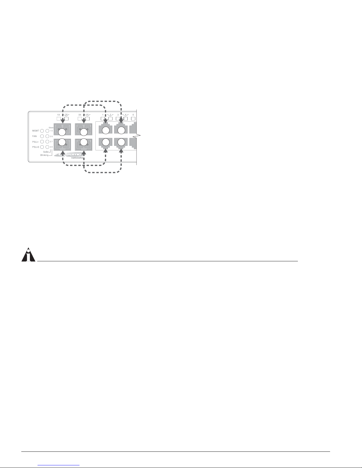
The four fiber ports and the first four of the 10/100/1000BASE-T ports are designed as combination
ports for uplink redundancy. When sharing ports, only the fiber port or only the copper port can be
active at the same time. If copper port 1 goes down while transmittin g packets, fiber port 1X activates
and becomes the primary link. Se e Figure 4 for a diagram of these com bination ports.
Table 8: Minimum attenuation requirements
Receivers
GBIC Type LX70 LX100
ZX (prior to
Rev 03)
ZX Rev 03 ZX mini
Transceivers
LX70 9 dB 13 dB 7 dB 7 dB 9 dB
LX100 8 d B 12 dB 6 dB 6 dB 8 dB
ZX (prior to
Rev 03)
2 dB 6 dB 0 dB 0 dB 2 dB
ZX Rev 03 5 dB 9 dB 3 dB 3 dB 5 dB
ZX mini 6 dB 10 dB 4 dB 4 dB 6 dB
XM_04
1
ZX GBIC
ZX GBIC
Rev. 03
ZX GBIC
Rev. 03
ZX GBIC
Rev. 03
21.0 dB
19.5 dB
ZX GBIC ZX GBIC
LX70 LX70
18.0 dB
23.5 dB
ZX GBIC LX70
29.0 dB
23.0 dB
19.0 dB
21.5 dB
23.0 dB
20.0 dB
LX70 LX100
LX100
LX100
30.0 dB
ZX GBIC
ZX GBIC
Rev. 03
LX100 LX100
25.0 dB
24.5 dB
27.0 dB
24.0 dB
LX70
ZX GBIC
Rev. 03
22.0 dB
28 ExtremeWare 7.2e I nstallation an d User Guid e
Summit 400-48t Switch Overview and In stallation
The switch determines whether the port is the primary or redundant port based upon the order in
which the cables are inserted into the switch. When the switch senses that cables are in both the fiber
and corresponding copper port, the switch enables the uplink redundancy feature. For example, if you
insert mini-GBICs into ports 1X and 3X first, and then connect copper ports 1 and 3, the switch assigns
ports 1 and 3 as redundant ports.
Figure 4: Redundancy cabling
You can override the configurati on and behavior of these ports through the CLI. Us ing the CLI, you can
set a preference for either fiber or copper. You can also turn off port redundancy using the force option.
If a combination port fails to link, determine whether the force option is in effect. For more information
about using the CLI to set redundancy priority, see “Configuring Ports” on page 81.
The Summit 400-48 switch G igabit Ethernet port failover from the fiber link to t he copper link takes 4-5
seconds. The Summit 400-48t sw itch Gigabit Eth ernet port failover from the copper link to the fiber l ink
takes 2-3 seconds.
NOTE
To support automatic failove r between the fiber and co pper ports, you must use a n Extreme mini-GBIC
connector.
Software Overview
Virtual LANs (VLANs)
ExtremeWare has a VLAN feature that enables y ou to construct your broadcast domains without being
restricted by physical connections. A VLAN is a group of location- and topolog y-independent devices
that communicate as if they were on the same physical local area network (LAN).
Implementing VLANs on your network has the following three advantages:
• VLANs help to control broadcast traffic. If a device in VLAN Marketing transmits a broadcast frame,
only VLAN Marketing devices receive the frame.
• VLANs provide extra security. Devices in VLAN Marketing can only communicate with devices on
VLAN Sales using routing services.
• VLANs ease the change and movem ent of devices on netw orks.
1
2
3
4
1
2
3
4
ES4K019

Software Overv iew
ExtremeWare 7.2e Installation and User Guide 29
For more information on VLANs, see Cha pter 5.
Spanning Tree Protocol
The switch supports the IEEE 80 2.1D Spanning Tree Protocol (STP), which is a bridge-based mechanism
for providing fault tolerance on networks. STP ena bles you to implement parallel paths for network
traffic, and ensure that:
• Redundant paths are disabled when the main paths are operational.
• Redundant paths are enabled if the main traffic paths fail.
A single spanning tree can span m ultiple VLANs.
For more information on STP, see Chapter 11.
Quality of Service
ExtremeWa re has Policy-Based Quality of Service (QoS) features that enable yo u to specify service levels
for different traffic groups. By default, all traffic is assigned the normal QoS policy profile. If needed,
you can create other QoS policies and apply them to different traffic types so that they have different
guaranteed minimum bandwidth, maximum bandwidth, and priority. For more informa tion on Quality
of Service, see Chapter 7.
Unicast Routing
The switch can route IP traffic between the VLANs that are configured as virtual router interfaces. Both
dynamic and static IP routes are maintained in the routing table. Th e following routing protocols are
supported:
• RIP version 1
• RIP version 2
• OSPF version 2
For more information on IP unic ast routing, see Chapter 12.
IP Multicast Routin g
The switch can use IP multicasti ng to allow a single IP ho st to transmit a packet to a group of IP hosts.
ExtremeWare supports mul ticast routes that are learned by way of the Protocol Independent Multicast
(sparse mode). For more information on IP multicast routing, see Chapter 14.
Load Sharing
Load sharing allows you to increase bandwidth and resiliency by usi ng a group of ports to carry traffic
in parallel between systems. The load sh aring algorithm allows the sw itch to use multiple ports as a
single logical port. For example, VLANs see the load -sharing group as a single virtual po rt. The
algorithm also guarantees packet sequencing between clients. For more information on load sharin g, see
Chapter 4.

30 ExtremeWare 7.2e I nstallation an d User Guid e
Summit 400-48t Switch Overview and In stallation
ESRP-Aware Switches
Extreme switches that are not running ESRP, but are connected on a network that has other Extreme
switches running ESRP are ESRP-aware. When ESRP-aware switches are attached to ESRP-enabled
switches, the ESRP-aware switches reliably perform fail -over and fail-back scenarios in t he prescribed
recovery times. No configuration of th is feature is necessary.
NOTE
If you disable EDP on the switch, the switch is no lon ger ESRP-aware.
If Extreme switches running ESRP are connected to layer 2 switches that are not manufactured by
Extreme Networks (or Extreme switches that are not running ExtremeWare 4.0 or later), the fail-over
times seen for traffic local to the segment may appear longer, depending on the application involved
and the FDB timer used by the other vendor ’s layer 2 switch. As such, ESRP can be used with layer 2
switches from other vendors, but the recovery times vary.
The VLANs associated with the ports connecting an ESRP-aware switch to an ESRP-enabled switch
must be configured using an 802.1Q tag on the con necting port, or, if only a single VLAN is involved, as
untagged.
To display ESRP-aware information, us e the following command:
show esrp-aware [vlan <vlan name>]
The display includes the group number, MAC address for the master of the group, and age of the
information.
Software Licensing
Some Extreme Networks products have capabilities that are enabled by usin g a license key. Keys are
typically unique to the switch, and a re not transferable. Keys are stored in NVRAM and, once entered,
persist through re boots, softwa re upgrad es, and reconfiguration s. The following sections describe the
features that are associated with license keys.
Router Licensing
Some switches support software licensing for different levels of router functionality. In the
Summit 400-48t, routing protocol support is separated into two sets: Edge and Advanced Edge. Edge is
a subset of Advanced Edge.
Edge Functionality
Edge functionality requires no license key. Extreme switches that ship with an Edge license, do not
require a license key. Edge functionality includes all sw itching functions, and al so includes all a vailable
layer 3 QoS, access list, and ESRP functions. L3 routing functions include support for:
• IP routing using RIP version 1 and/ or RIP version 2
• IP routing between directly attached VLANs
• IP routing using static routes
• ESRP-aware
 Loading...